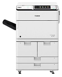
Canon imageRUNNER Advance 6555iPRT
Рейтинг

 Снят с производства
Тип устройства
Принтер
Технология печати
лазерная
Макс. формат
A3
Скорость печати
A4
55
Цветность печати
черно-белая
Общие характеристики |
|
|---|---|
Печать фотографий |
|
Телефон |
|
Факс |
|
Сканер |
|
Копир |
|
Тип устройства |
Принтер |
Цветность печати |
|
Технология печати |
лазерная |
Тип |
лазерный/светодиодный |
Макс. формат |
A3 |
Размещение |
напольный |
Принтер |
|
Печать без полей |
|
Пигментные чернила |
|
Макс, ширина отпечатка |
297 |
Время разогрева |
30 |
Макс, длина отпечатка |
420 |
Двусторонняя печать |
|
Макс, разрешение для ч/б печати |
|
| По Y | 1 200 |
| По X | 1 200 |
Скорость ч/б печати |
|
| A4 | 55 |
| A3 | 32 |
Время выхода первого отпечатка |
|
| Ч/б | 3,3 |
Сканер |
|
Слайд-адаптер |
|
Отправка изображения по e-mail |
|
Стандарт WIA |
|
Стандарт TWAIN |
|
Расходные материалы |
|
Ресурс ч/б картриджа/тонера |
56 000 |
Количество картриджей |
1 |
Печать на: |
|
| Матовой бумаге |
|
| Конвертах |
|
| Карточках |
|
| Этикетках |
|
| Глянцевой бумаге |
|
| Пленках |
|
| Фотобумаге |
|
| Рулоне |
|
| CD/DVD |
|
Плотность бумаги |
|
| Минимальная | 52 |
| Максимальная | 256 |
Факс |
|
Цветной |
|
PC Fax |
|
Телефон |
|
АОН |
|
Спикерфон |
|
Стандарт DECT |
|
Автоответчик |
|
Caller ID |
|
Беспроводная трубка |
|
Проводная трубка |
|
Шрифты и языки управления |
|
Языки управления |
|
| PCL 5c |
|
| PCL 6 |
|
| PCL 5e |
|
| PostScript | опционально |
Количество установленных шрифтов |
|
| PCL | 93 |
| PostScript | 136 |
Лотки |
|
Емкость лотка ручной подачи |
100 |
Подача бумаги |
|
| Максимальная | 7 700 |
| Стандартная | 4 200 |
Вывод бумаги |
|
| Стандартный | 250 |
| Максимальный | 3 500 |
Интерфейсы |
|
AirPrint |
|
LPT |
|
Bluetooth |
|
Инфракрасный порт |
|
RS-232 |
|
Устройство для чтения карт памяти |
|
FireWire (IEEE 1394) |
|
Версия USB |
2,0 |
Веб-интерфейс |
|
Wi-Fi 802.11n |
|
Wi-Fi |
|
USB |
|
Ethernet (RJ-45) |
|
Память/Процессор |
|
Емкость жесткого диска |
250 |
Объем памяти |
3 072 |
Дополнительная информация |
|
Экран |
|
Диагональ дисплея |
10,1 |
Работа от аккумулятора |
|
Поддержка ОС |
|
| Mac OS |
|
| Windows |
|
Потребляемая мощность |
|
| В режиме ожидания | 238 |
| При работе | 2 400 |
Уровень шума |
|
| При работе | 75 |
| В режиме ожидания | 56 |
Габариты |
|
Высота |
670 |
Глубина |
1 220 |
Вес |
234 |
Ширина |
779 |
Модули
932 MAIN CONTROLLER PCB ASSY, 2
100R EXTERNAL COVERS, PANELS, ETC. (iR-ADV 6575i 230V)
112 FRONT COVER ASSY, LOWER
621 HOPPER ASSY
B32 OPEN/CLOSE GUIDE ASSEMBLY (ADF)
811B ( 1 / 2 ) FIXING ASSY, UPPER
271B DEVELOPING DRIVE ASSY
352 INNER PAPER DELIVERY ASSY
962A NOISE FILTER PCB ASSEMBLY(100V,120V)
931C MAIN CONTROLLER PCB ASSY, 1 (iR-ADV 6565 series)
330 ( 3 / 3 ) FIXING/FEEDER DUPLEXING ASSY
140C ( 1 / 2 ) POWER CORD TERMINAL ASSY (230V)
720 SEPARATION CLAW DRIVE ASSEMBLY
300 CASSETTE ASSEMBLY
B14 INTERNAL COMPONENTS 5 (ADF)
811B ( 2 / 2 ) FIXING ASSY, UPPER
114 VERTICAL PATH ASSEMBLY
301 CST. SIZE/REMNANT DETECT ASSY
336 REVERSE CROSSMEMBER ASSY, LF.
100N EXTERNAL COVERS, PANELS, ETC. (iR-ADV 6575i 120V)
770 WASTE TONER FEED ASSEMBLY
570B PRE-TRANSFER CORONA ASSY
B12 INTERNAL COMPONENTS 3 (ADF)
334 E.T.B. CLEANING ASSEMBLY
961A AC DRIVER PCB ASSY (100V,120V)
100P EXTERNAL COVERS, PANELS, ETC. (iR-ADV 6555i 230V)
D10B EXTERNAL COVERS, PANELS, ETC. (READER A/INCH)
B41 PLATEN ROLLER ASSEMBLY, 2 (ADF)
930B DC CONTROLLER PCB ASSY
620B HOPPER ASSY
931D MAIN CONTROLLER PCB ASSY, 1 (iR-ADV 6575 series)
814B FIXING EXIT GUIDE ASSY
351 ( 2 / 2 ) REVERSE PAPER DELIVERY ASSY
510E PHOTO-SENSITIVE DRUM ASSEMBLY (120V)
460B LASER SCANNER UNIT
101A INTERNAL COMPONENTS 1 (100V,230V AU,SG,IN,KR,LTN)
350B OUTER PAPER DELIVERY ASSY
261 LEFT DECK PICK-UP DRIVE ASSY
813B FIXING ENTRANCE GUIDE ASSY
963 DUPLEXING DRIVER PCB ASSEMBLY
910C IH POWER SUPPLY PCB ASSY (230V)
303 CASSETTE SIZE DETECT ASSY
810C FIXING ASSY
140E ( 1 / 2 ) POWER CORD TERMINAL ASSY (120V)
900B CONTROLLER BOX ASSEMBLY
711B DRUM CLEANING ASSY
B10B INTERNAL COMPONENTS 1 (ADF A/INCH)
270B DRUM DRIVE ASSY
D90 READER CONTROLLER PCB ASSEMBLY (READER)
260 V. PATH/CST. PICK-UP ASSY
650 DEVELOPING RELEASE ASSY
510F PHOTO-SENSITIVE DRUM ASSEMBLY (230V)
980 H.V. POWER SUPPLY ASSY
B43 PAPER FEED GUIDE ASSEMBLY, 2 (ADF)
140C ( 2 / 2 ) POWER CORD TERMINAL ASSY (230V)
B40 PLATEN ROLLER ASSEMBLY, 1 (ADF)
311B PAPER PICK-UP ASSY, LEFT
351 ( 1 / 2 ) REVERSE PAPER DELIVERY ASSY
710B ( 1 / 2 ) HOLDER UNIT, DRUM UNIT
D12 INTERNAL COMPONENTS 2 (READER)
106B INTERNAL COMPONENTS 6
100M EXTERNAL COVERS, PANELS, ETC. (iR-ADV 6565i 120V)
B11D INTERNAL COMPONENTS 2 (ADF A/B/K/INCH)
108 MACHINE BOTTOM PLATE
910B IH POWER SUPPLY PCB ASSY (100V,120V)
B90 DF DRIVER PCB ASSEMBLY (ADF)
140E ( 2 / 2 ) POWER CORD TERMINAL ASSY (120V)
B42 PAPER FEED GUIDE ASSEMBLY, 1 (ADF)
104D INTERNAL COMPONENTS 4
113 RIGHT DOOR ASSEMBLY
250 MAIN DRIVE ASSY
310B PAPER PICK-UP ASSY, RIGHT
130B FLAT CONTROL PANEL ASSEMBLY
330 ( 1 / 3 ) FIXING/FEEDER DUPLEXING ASSY
331 ( 1 / 2 ) FIXING/FEEDER FRAME ASSY
B11B INTERNAL COMPONENTS 2 (ADF A/INCH)
B19 WHITE PLATE ASSEMBLY (ADF)
331 ( 2 / 2 ) FIXING/FEEDER FRAME ASSY
816 SHAFT FIXED PLATE ASSY, REAR
812B FIXING DRIVE ASSY
640B DEVELOPING ASSY
961B AC DRIVER PCB ASSY (230V)
102 INTERNAL COMPONENTS 2
100L EXTERNAL COVERS, PANELS, ETC. (iR-ADV 6555i 120V)
109B MACHINE REAR PLATE 1
312F MULTI TRAY ASSEMBLY (A/INCH)
931B MAIN CONTROLLER PCB ASSY, 1 (iR-ADV 6555 series)
815 SHAFT FIXED PLATE ASSY, FRONT
D10D EXTERNAL COVERS, PANELS, ETC. (READER A/B/K/INCH)
332 REGISTRATION ASSY
101B INTERNAL COMPONENTS 1 (120V,230V EUR)
302 DECK REMNANT DETECT ASSY
105B INTERNAL COMPONENTS 5
107C INTERNAL COMPONENTS 7
110 MACHINE REAR PLATE 2
B13 INTERNAL COMPONENTS 4 (ADF)
330 ( 2 / 3 ) FIXING/FEEDER DUPLEXING ASSY
B17 OPEN/CLOSE PANEL ASSEMBLY (ADF)
B30 PAPER PICK-UP ASSEMBLY (ADF)
D11 INTERNAL COMPONENTS 1 (READER)
B31 PAPER DELIVERY ASSEMBLY (ADF)
B10D INTERNAL COMPONENTS 1 (ADF A/B/K/INCH)
710B ( 2 / 2 ) HOLDER UNIT, DRUM UNIT
111B MACHINE REAR PLATE 3
312H MULTI TRAY ASSEMBLY (AB/K/INCH)
B18 BASE FRAME ASSEMBLY (ADF)
960 MAIN DRIVE DRIVER PCB ASSY
100Q EXTERNAL COVERS, PANELS, ETC. (iR-ADV 6565i 230V)
B16 DOCUMENT TRAY ASSEMBLY (ADF)
550 1ST CORONA ASSY
304 PAPER STOCK ASSY, RIGHT
962B NOISE FILTER PCB ASSEMBLY(230V)
335 E.T.BELT ASSEMBLY
333 PHOTO SENSOR ASSY
964 FEED DRIVER PCB ASSEMBLY
103 INTERNAL COMPONENTS 3
315 PRE-REGISTRATION GUIDE ASSY
280 DELIVERY REVERSE DRIVE ASSY
313 MULTI PAPER PICK-UP ASSY
B15 INTERNAL COMPONENTS 6 (ADF)
625 BUFFER ASSY
305 PAPER STOCK ASSY, LEFT
Детали 111B MACHINE REAR PLATE 3

| Деталь: | MAIN CONTROLLER PCB ASSY, 2 |
| Парткод: | FM1-M962-000 |
| Деталь: | PIN |
| Парткод: | FB6-6644-000 |
| Деталь: | WASHER |
| Парткод: | FC2-2121-000 |
| Деталь: | COVER, MAIN SWITCH |
| Парткод: | FC8-1844-000 |
| Деталь: | HINGE, DOOR |
| Парткод: | FC9-7047-000 |
| Деталь: | FRONT COVER ASSEMBLY, UPPER |
| Парткод: | FM1-H208-000 |
| Деталь: | SCREW, STEPPED, M4 |
| Парткод: | FS5-9217-010 |
| Деталь: | FLAG, BOTTLE DOOR SENSOR |
| Парткод: | FC9-8073-000 |
| Деталь: | LABEL, BOTTLE INSERT CAUTION |
| Парткод: | FC9-9055-000 |
| Деталь: | LABEL, LEVER OPERATOR CAUTION |
| Парткод: | FC9-9057-000 |
| Деталь: | LABEL, CONNECTION CAUTION |
| Парткод: | FU5-9905-000 |
| Деталь: | SCREW, M4X12.2 |
| Парткод: | FE4-1272-000 |
| Деталь: | PLATE, COVER AUXILIARY, RIGHT |
| Парткод: | FE4-1280-000 |
| Деталь: | COVER, RIGHT REAR, 1 |
| Парткод: | FE4-1312-000 |
| Деталь: | COVER, SIDE |
| Парткод: | FE4-1331-000 |
| Деталь: | COVER, LEFT REAR |
| Парткод: | FE4-1639-000 |
| Деталь: | LABEL, WIRE HEIGHT |
| Парткод: | FU7-8495-000 |
| Деталь: | COVER, CASSETTE, LOWER |
| Парткод: | FE4-5159-000 |
| Деталь: | COVER, KNOB |
| Парткод: | FE4-5160-000 |
| Деталь: | COVER, RIGHT FRONT |
| Парткод: | FE4-5161-000 |
| Деталь: | COVER, RIGHT LOWER |
| Парткод: | FE4-5162-000 |
| Деталь: | COVER, RIGHT REAR, 2 |
| Парткод: | FE4-5163-000 |
| Деталь: | COVER, LEFT, LOWER |
| Парткод: | FE4-5164-000 |
| Деталь: | COVER, PAPER DELIVERY |
| Парткод: | FE4-5165-000 |
| Деталь: | SPRING, TORSION |
| Парткод: | FU8-2348-000 |
| Деталь: | COVER, BLANKING, 1 |
| Парткод: | FE4-5167-000 |
| Деталь: | COVER, BLANKING, 2 |
| Парткод: | FE4-5168-000 |
| Деталь: | COVER, LEFT FRONT |
| Парткод: | FE4-5169-000 |
| Деталь: | COVER, UPPER REAR |
| Парткод: | FE4-5171-000 |
| Деталь: | COVER, LEFT UPPER |
| Парткод: | FE4-5172-000 |
| Деталь: | COVER, REAR LOWER |
| Парткод: | FE4-5175-000 |
| Деталь: | COVER, BLANKING, 3 |
| Парткод: | FE4-5188-000 |
| Деталь: | COVER, BLANKING |
| Парткод: | FE4-5189-000 |
| Деталь: | SEAL |
| Парткод: | FE4-5428-000 |
| Деталь: | LABEL, USB LAN INDICATION |
| Парткод: | FE4-5882-000 |
| Деталь: | LABEL, DRUM HEATER |
| Парткод: | FE4-5897-000 |
| Деталь: | CAP |
| Парткод: | FE4-7426-000 |
| Деталь: | SPRING, TORSION |
| Парткод: | FU8-2349-000 |
| Деталь: | SCREW,RS,M4X10 |
| Парткод: | XA9-0899-000 |
| Деталь: | CATCH, MAGNET |
| Парткод: | XZ9-0603-000 |
| Деталь: | COVER, FILTER CASE |
| Парткод: | FL0-5100-000 |
| Деталь: | COVER, RIGHT UPPER |
| Парткод: | FL0-6121-000 |
| Деталь: | COVER, BOX, LEFT |
| Парткод: | FL0-6130-000 |
| Деталь: | COVER, FRONT, UPPER |
| Парткод: | FL0-7667-000 |
| Деталь: | LABEL, SERVICE |
| Парткод: | FL3-3872-000 |
| Деталь: | WASTE TONER BOTTLE BOX COVER |
| Парткод: | FM1-H203-000 |
| Деталь: | LABEL, TONER BOTTLE CAUTION |
| Парткод: | FE3-4772-000 |
| Деталь: | COVER, CONTROL PANEL, RIGHT |
| Парткод: | FE4-1801-000 |
| Деталь: | COVER, CONTROL PANEL ASSY |
| Парткод: | FE4-5166-000 |
| Деталь: | CABLE, USER INTERFACE |
| Парткод: | FK4-2498-000 |
| Деталь: | CABLE, USB |
| Парткод: | FK4-2499-000 |
| Деталь: | EXTERNAL COVERS, PANELS, ETC. |
| Парткод: | NPN |
| Деталь: | SHAFT, HINGE |
| Парткод: | FB2-7867-030 |
| Деталь: | COVER, KNOB |
| Парткод: | FE4-5206-000 |
| Деталь: | PANEL, FRONT, LOWER |
| Парткод: | FL0-6151-000 |
| Деталь: | PLATE, COVER SWITCH, FRONT |
| Парткод: | FC8-9646-000 |
| Деталь: | SPRING, TORSION |
| Парткод: | FU7-2709-000 |
| Деталь: | SPRING, TORSION |
| Парткод: | FU7-2710-000 |
| Деталь: | SEAL, FRONT COVER, 1 |
| Парткод: | FC8-9639-000 |
| Деталь: | SEAL, FRONT COVER, 3 |
| Парткод: | FC8-9641-000 |
| Деталь: | SEAL, FRONT COVER, 4 |
| Парткод: | FC8-9642-000 |
| Деталь: | SUPPORT, HINGE |
| Парткод: | FC8-9647-000 |
| Деталь: | SEAL, FRONT COVER, E |
| Парткод: | FC9-8850-000 |
| Деталь: | SEAL, FRONT COVER, 5 |
| Парткод: | FC9-6171-000 |
| Деталь: | FRONT COVER ASSY, LOWER |
| Парткод: | FM1-H381-000 |
| Деталь: | BUSHING |
| Парткод: | XG9-0737-000 |
| Деталь: | SHAFT, RING |
| Парткод: | FC6-2327-000 |
| Деталь: | STOPPER, FRONT |
| Парткод: | FC6-3230-000 |
| Деталь: | SHUTTER, TONER CASE |
| Парткод: | FC8-7139-000 |
| Деталь: | SUPPORT, HINGE |
| Парткод: | FC9-0160-000 |
| Деталь: | LEVER, OPERATOR |
| Парткод: | FC9-6942-000 |
| Деталь: | LABEL, LEVER POSITION |
| Парткод: | FC9-9054-000 |
| Деталь: | ROLLER, BOTTLE BOX LIMIT |
| Парткод: | FC9-9196-000 |
| Деталь: | CAM UNIT |
| Парткод: | FM4-0880-010 |
| Деталь: | BOTTLE DRIVE UNIT |
| Парткод: | FM4-5309-000 |
| Деталь: | SCREW,STEPPED |
| Парткод: | FS5-9438-030 |
| Деталь: | BUSHING |
| Парткод: | FU6-1197-000 |
| Деталь: | GEAR, 28T |
| Парткод: | FU7-0841-000 |
| Деталь: | GEAR, BEVEL, 13T/48T |
| Парткод: | FU0-0055-000 |
| Деталь: | GEAR, BEVEL, 16T |
| Парткод: | FU0-0054-000 |
| Деталь: | GEAR, 17T/47T |
| Парткод: | FU9-0078-000 |
| Деталь: | GEAR, 25T |
| Парткод: | FU9-0079-000 |
| Деталь: | GEAR, 18T |
| Парткод: | FU9-0080-000 |
| Деталь: | CONNECTOR, SNAP TIGHT, BK |
| Парткод: | VS1-7177-006 |
| Деталь: | CONNECTOR, SNAP TIGHT, BL |
| Парткод: | VS1-8412-003 |
| Деталь: | IC, PHOTO-INTERRUPTER |
| Парткод: | WG8-5848-000 |
| Деталь: | SCREW,RS,M3X8 |
| Парткод: | XA9-1386-000 |
| Деталь: | RING, E |
| Парткод: | XD9-0134-000 |
| Деталь: | RING, E |
| Парткод: | XD9-0137-010 |
| Деталь: | PIN, PARALLEL |
| Парткод: | XD9-0293-000 |
| Деталь: | COVER, SET ON, RIGHT |
| Парткод: | FL3-7917-000 |
| Деталь: | CABLE, HOPPER UNIT |
| Парткод: | FM4-0998-000 |
| Деталь: | CAM, BOTTLE |
| Парткод: | FL3-7929-000 |
| Деталь: | SEAL, HOPPER |
| Парткод: | FL0-1826-000 |
| Деталь: | SHAFT, LEVER |
| Парткод: | FU6-4982-000 |
| Деталь: | HOPPER ASSY |
| Парткод: | NPN |
| Деталь: | FLAG, WIDTH SENSOR, LOWER |
| Парткод: | FC8-5761-000 |
| Деталь: | GUIDE, OPEN/CLOSE, UPPER |
| Парткод: | FL0-1454-000 |
| Деталь: | CABLE, SENSOR |
| Парткод: | FM1-K817-000 |
| Деталь: | SPRING, TORSION |
| Парткод: | FU7-2556-000 |
| Деталь: | IC,PHOTO-INTERRUPTER,LG248NL1A |
| Парткод: | WG8-5783-000 |
| Деталь: | OPEN/CLOSE GUIDE ASSEMBLY |
| Парткод: | NPN |
| Деталь: | ROD, PLATE MOUNTING |
| Парткод: | FA6-3071-020 |
| Деталь: | ROLLER, CLEANING |
| Парткод: | FA9-3860-000 |
| Деталь: | BUSHING |
| Парткод: | FB1-6833-000 |
| Деталь: | ROWEL |
| Парткод: | FB1-8776-000 |
| Деталь: | PLATE, LIMIT, ARM |
| Парткод: | FB2-7219-030 |
| Деталь: | PLATE, SUPPORT |
| Парткод: | FB2-7221-000 |
| Деталь: | SHAFT, ONE-WAY |
| Парткод: | FB2-7230-000 |
| Деталь: | BEARING,BALL,6809ZZN S1C4 |
| Парткод: | XG9-0563-000 |
| Деталь: | HOLDER, SHAFT |
| Парткод: | FB5-5521-000 |
| Деталь: | STOPPER,CLAW,FRONT |
| Парткод: | FC6-3499-000 |
| Деталь: | STOPPER,CLAW,REAR |
| Парткод: | FC6-3500-000 |
| Деталь: | RETAINER,FIXING ROLLER,THRUST |
| Парткод: | FC6-3501-020 |
| Деталь: | STOPPER,HOPPER,R IGHT |
| Парткод: | FC6-3524-000 |
| Деталь: | SHUTTER |
| Парткод: | FC6-3525-000 |
| Деталь: | HOLDER,THERMISTOR INNER,RIGHT |
| Парткод: | FC6-3588-000 |
| Деталь: | HOLDER,MAIN THERMISTOR |
| Парткод: | FC6-3592-000 |
| Деталь: | SPRING, LEAF |
| Парткод: | FC6-3596-000 |
| Деталь: | COVER, CROSSMEMBER, RIGHT |
| Парткод: | FC6-3628-000 |
| Деталь: | GUIDE,CORD,R IGHT |
| Парткод: | FC6-3669-000 |
| Деталь: | RETAINER,BEARING |
| Парткод: | FC6-3673-000 |
| Деталь: | HOLDER, ROLLER |
| Парткод: | FC6-3808-000 |
| Деталь: | CLEANER SUPPLY ROLL |
| Парткод: | FY1-1157-000 |
| Деталь: | TERMINAL, ROLLER GROUNDING |
| Парткод: | FC7-7717-000 |
| Деталь: | SPRING |
| Парткод: | FC7-7800-000 |
| Деталь: | BELT, HANDLE |
| Парткод: | FL0-5207-000 |
| Деталь: | RING, E |
| Парткод: | XD9-0137-010 |
| Деталь: | HOLDER, SUB THERMISTOR, RIGHT |
| Парткод: | FC8-9512-000 |
| Деталь: | CLAMP,WIRE |
| Парткод: | WT2-6237-000 |
| Деталь: | BUSHING |
| Парткод: | FM1-C081-010 |
| Деталь: | LEVER, CLEANER REMNANT SENSING |
| Парткод: | FC9-8282-000 |
| Деталь: | FIXING ROLLER SET |
| Парткод: | FM0-3465-030 |
| Деталь: | THERMISTOR UNIT, MAIN |
| Парткод: | FK2-7683-000 |
| Деталь: | THERMISTOR UNIT, SUB |
| Парткод: | FK2-7693-000 |
| Деталь: | THERMOSWITCH |
| Парткод: | FK2-7698-000 |
| Деталь: | SUPPORT,SHAFT |
| Парткод: | FL2-3049-000 |
| Деталь: | PLATE,ROLL SHAFT,REAR |
| Парткод: | FL2-3051-000 |
| Деталь: | SHAFT, DRIVE |
| Парткод: | FL2-3058-000 |
| Деталь: | RING, E |
| Парткод: | XD9-0136-000 |
| Деталь: | ARM, ONE-WAY |
| Парткод: | FL3-2159-000 |
| Деталь: | RING, E |
| Парткод: | XD9-0134-000 |
| Деталь: | WASHER, FRONT PANEL ARM, S |
| Парткод: | XD9-0067-000 |
| Деталь: | FIXING HEATER UNIT |
| Парткод: | FM3-7359-010 |
| Деталь: | SCREW, MACH. TRUSS HEAD, M4X6 |
| Парткод: | XA9-1031-000 |
| Деталь: | BUSHING, PL |
| Парткод: | FS1-1449-000 |
| Деталь: | TWO-STEP SCREW, M3 |
| Парткод: | FS1-9009-020 |
| Деталь: | BUSHING |
| Парткод: | FS2-1256-000 |
| Деталь: | SPRING, TENSION |
| Парткод: | FU8-2523-000 |
| Деталь: | SPRING, TENSION |
| Парткод: | FS5-2940-000 |
| Деталь: | SCREW, STEPPED |
| Парткод: | FS5-9162-020 |
| Деталь: | GEAR, 28T |
| Парткод: | FS6-0103-000 |
| Деталь: | GEAR, 60T |
| Парткод: | FS7-0891-000 |
| Деталь: | GEAR, 22T/60T |
| Парткод: | FS6-0105-000 |
| Деталь: | GEAR, 23T |
| Парткод: | FS6-0106-000 |
| Деталь: | GEAR, 50T |
| Парткод: | FS6-0107-000 |
| Деталь: | GEAR |
| Парткод: | FS6-0134-000 |
| Деталь: | BUSHING |
| Парткод: | FU5-1468-000 |
| Деталь: | BUSHING |
| Парткод: | FU6-1193-000 |
| Деталь: | SPRING |
| Парткод: | FU6-2107-000 |
| Деталь: | IC, PHOTO-INTERRUPTER,LG248NL1 A |
| Парткод: | WG8-5783-000 |
| Деталь: | GEAR, 52T |
| Парткод: | FU8-0505-000 |
| Деталь: | SPRING, TENSION |
| Парткод: | FU8-2315-000 |
| Деталь: | SPRING, TENSION |
| Парткод: | FU8-2316-000 |
| Деталь: | SPRING, TORSION |
| Парткод: | FU8-2516-000 |
| Деталь: | CONNECTOR, SNAP TIGHT, BK |
| Парткод: | VS1-7177-004 |
| Деталь: | GUIDE,COIL CORD |
| Парткод: | FC6-3447-000 |
| Деталь: | SPACER |
| Парткод: | FC8-7213-000 |
| Деталь: | GEAR, 22T/63T |
| Парткод: | FS7-0893-000 |
| Деталь: | GEAR, 19T/63T |
| Парткод: | FS7-0894-000 |
| Деталь: | GEAR, 19T/60T |
| Парткод: | FS7-0895-000 |
| Деталь: | COVER, FIXING, UPPER |
| Парткод: | FC9-7840-000 |
| Деталь: | PLATE, LIMIT, ARM, 2 |
| Парткод: | FC9-5137-000 |
| Деталь: | CABLE, FIXING CLEANER |
| Парткод: | FM4-0990-000 |
| Деталь: | PIN, PARALLEL |
| Парткод: | XD9-0289-000 |
| Деталь: | CABLE, MOTOR |
| Парткод: | FM4-0991-000 |
| Деталь: | SUPPORT,THERMISTOR INNER,RIGHT |
| Парткод: | FC6-3587-000 |
| Деталь: | SUPPORT, MAIN THERMISTOR |
| Парткод: | FC6-3591-000 |
| Деталь: | STOPPER, FIXING ROLLER, UPPER |
| Парткод: | FE4-5931-000 |
| Деталь: | STOPPER, FIXING ROLLER, LOWER |
| Парткод: | FE4-5932-000 |
| Деталь: | WASHER,COP |
| Парткод: | XD1-1106-235 |
| Деталь: | PIN,SPRING |
| Парткод: | XD3-1300-122 |
| Деталь: | FIXING ASSY, UPPER |
| Парткод: | FM3-7358-050 |
| Деталь: | SPRING, TENSION |
| Парткод: | FC8-7125-000 |
| Деталь: | ROLLER |
| Парткод: | FC8-9495-000 |
| Деталь: | MOTOR, DC |
| Парткод: | FK2-7667-000 |
| Деталь: | CLUTCH, ELECTROMAGNETIC |
| Парткод: | FK2-7684-000 |
| Деталь: | GEAR, 29T |
| Парткод: | FL3-2169-000 |
| Деталь: | SUPPORT, CLUTCH |
| Парткод: | FL3-2806-000 |
| Деталь: | PLATE, DEVELOPING DRIVE, 1 |
| Парткод: | FL3-2807-000 |
| Деталь: | GEAR, 30T |
| Парткод: | FL3-3869-000 |
| Деталь: | GEAR, 50T/32T |
| Парткод: | FL3-4560-000 |
| Деталь: | GEAR, 40T |
| Парткод: | FL3-4575-000 |
| Деталь: | GEAR, 38T |
| Парткод: | FU5-0236-000 |
| Деталь: | GEAR, 30T |
| Парткод: | FU6-0562-000 |
| Деталь: | GEAR, 30T |
| Парткод: | FU6-0603-000 |
| Деталь: | RING, E |
| Парткод: | XD9-0136-000 |
| Деталь: | RING, E |
| Парткод: | XD9-0137-010 |
| Деталь: | PIN, PARALLEL |
| Парткод: | XD9-0292-000 |
| Деталь: | BEARING, BALL, LNR-1680KKR |
| Парткод: | XG9-0794-000 |
| Деталь: | PULLEY, 28T |
| Парткод: | FU9-0157-000 |
| Деталь: | PIN, PARALLEL |
| Парткод: | XD9-0289-000 |
| Деталь: | DEVELOPING DRIVE ASSY |
| Парткод: | FM3-7386-000 |
| Деталь: | BUSHING |
| Парткод: | FB2-7163-000 |
| Деталь: | RING, E |
| Парткод: | XD9-0136-000 |
| Деталь: | MOUNT, PIN |
| Парткод: | FC9-9071-000 |
| Деталь: | SUPPORT, PLATE |
| Парткод: | FF5-3055-030 |
| Деталь: | SHAFT, RECIPROCATING |
| Парткод: | FL3-3019-000 |
| Деталь: | BUSHING |
| Парткод: | FS5-1372-000 |
| Деталь: | SPRING, COMPRESSION |
| Парткод: | FS5-2953-020 |
| Деталь: | ROLLER, FEED |
| Парткод: | FC9-9187-000 |
| Деталь: | SPRING,TENSION |
| Парткод: | FS7-2319-000 |
| Деталь: | SPRING, TORSION |
| Парткод: | FE2-1022-000 |
| Деталь: | SCREW,M3X4 |
| Парткод: | XA9-1659-000 |
| Деталь: | HOLDER, FEED ROLLER |
| Парткод: | FC8-9343-000 |
| Деталь: | PLATE, RATCHET CLAW |
| Парткод: | FC9-5130-000 |
| Деталь: | GUIDE, PAPER |
| Парткод: | FC9-6947-000 |
| Деталь: | INNER PAPER DELIVERY ASSY |
| Парткод: | FM3-7381-000 |
| Деталь: | INDUCTOR |
| Парткод: | FH3-0937-000 |
| Деталь: | NOISE FILTER PCB ASSEMBLY |
| Парткод: | FM0-2958-000 |
| Деталь: | LABEL, MEMORY CAUTION |
| Парткод: | FC0-5049-000 |
| Деталь: | FAN |
| Парткод: | FK4-2852-000 |
| Деталь: | LABEL, CAUTION |
| Парткод: | FU8-8257-000 |
| Деталь: | SCREW, MACH. PAN HEAD, M3X4 |
| Парткод: | XA9-1979-000 |
| Деталь: | MAIN CONTROLLER PCB ASSY, 1 |
| Парткод: | FM1-K344-000 |
| Деталь: | RING, RETAINING |
| Парткод: | FB6-6088-000 |
| Деталь: | CAM, PRESSURE |
| Парткод: | FC5-2108-000 |
| Деталь: | FLAPPER, DUPLEXING REVERSE |
| Парткод: | FC6-1968-000 |
| Деталь: | BUSHING |
| Парткод: | FC6-9542-000 |
| Деталь: | RACK, RELEASE ARM |
| Парткод: | FC8-7192-010 |
| Деталь: | GUIDE, REVERSE, LEFT |
| Парткод: | FC8-7327-000 |
| Деталь: | GUIDE, REVERSE SWING |
| Парткод: | FC8-7328-000 |
| Деталь: | ROLLER, DUPLEXING PAPER FEED |
| Парткод: | FC9-5463-000 |
| Деталь: | PLATE, CLEANER GROUNDING |
| Парткод: | FC9-5700-000 |
| Деталь: | COVER, SENSOR |
| Парткод: | FC9-6182-000 |
| Деталь: | SPRING, TORSION |
| Парткод: | FC9-7845-000 |
| Деталь: | SHEET, FIXING CROSSMEMBER |
| Парткод: | FC9-8828-000 |
| Деталь: | STOPPER, HANDLE |
| Парткод: | FC9-9067-000 |
| Деталь: | GEAR, 26T |
| Парткод: | FE2-3468-000 |
| Деталь: | STOPPER, RELEASE GEAR |
| Парткод: | FE2-3469-000 |
| Деталь: | MOTOR, STEPPING, DC |
| Парткод: | FK2-7674-000 |
| Деталь: | PLATE, POSITIONING |
| Парткод: | FL3-0293-000 |
| Деталь: | LOCK, HANDLE |
| Парткод: | FL3-1306-010 |
| Деталь: | GEAR, 30T/PULLEY, 28T |
| Парткод: | FL3-2814-000 |
| Деталь: | CABLE, FIXING/FEEDER DRAWER |
| Парткод: | FM1-G118-000 |
| Деталь: | CONNECTOR, SNAP TIGHT, BK |
| Парткод: | VS1-7177-002 |
| Деталь: | CONNECTOR, SNAP TIGHT, BK |
| Парткод: | VS1-7177-003 |
| Деталь: | CONNECTOR, SNAP TIGHT, BK |
| Парткод: | VS1-7177-008 |
| Деталь: | HIGH VOLTAGE PCB ASSY |
| Парткод: | FM1-K905-000 |
| Деталь: | CABLE, TRANSFER HIGH VOLTAGE |
| Парткод: | FM4-1051-000 |
| Деталь: | CABLE, SIGNAL CONNECTING |
| Парткод: | FM1-P892-000 |
| Деталь: | LABEL, OPEN/CLOSE |
| Парткод: | FC9-9015-000 |
| Деталь: | HANDLE, OPEN/CLOSE |
| Парткод: | FC9-9102-000 |
| Деталь: | RING, E |
| Парткод: | XD9-0136-000 |
| Деталь: | MOTOR, STEPPING, DC |
| Парткод: | FK2-7675-000 |
| Деталь: | GEAR, 39T/PULLEY, 28T |
| Парткод: | FL3-3018-000 |
| Деталь: | GEAR, 25T |
| Парткод: | FS5-0395-000 |
| Деталь: | BELT, TIMING, COGGED |
| Парткод: | XF2-1606-260 |
| Деталь: | SPRING, GROUNDING |
| Парткод: | FC8-9664-000 |
| Деталь: | MOTOR, STEPPING, DC |
| Парткод: | FK2-7719-000 |
| Деталь: | GEAR, 26T/PULLEY, 30T |
| Парткод: | FL3-2171-000 |
| Деталь: | SCREW, W/WASHER, M3X6 |
| Парткод: | XA9-2003-000 |
| Деталь: | HANDLE, TRANSFER FRAME, LOWER |
| Парткод: | FC5-2386-000 |
| Деталь: | PLATE, GROUNDING |
| Парткод: | FC5-5170-000 |
| Деталь: | FLAG, CAM SENSOR |
| Парткод: | FC8-7171-000 |
| Деталь: | CAM, BELT PRESSURE |
| Парткод: | FC8-7200-000 |
| Деталь: | GEAR, 30T |
| Парткод: | FU9-0314-000 |
| Деталь: | RING, E |
| Парткод: | XD9-0137-010 |
| Деталь: | PIN, DOWEL |
| Парткод: | XD9-0301-000 |
| Деталь: | FIXING/FEEDER LOCK HANDLE UNIT |
| Парткод: | FM4-0912-010 |
| Деталь: | LEVER, RELEASE |
| Парткод: | FL3-7921-000 |
| Деталь: | SCREW,RS,M4X8 |
| Парткод: | XA9-0732-010 |
| Деталь: | SCREW, W/WASHER, M4X10 |
| Парткод: | XA9-0961-000 |
| Деталь: | FAN, COOLING |
| Парткод: | FH6-1548-040 |
| Деталь: | CABLE, MOTOR |
| Парткод: | FM4-1052-000 |
| Деталь: | CABLE, MOTOR |
| Парткод: | FM4-1053-000 |
| Деталь: | CABLE, MOTOR |
| Парткод: | FM4-1054-000 |
| Деталь: | CABLE, DUPLEXING FEED ASSY |
| Парткод: | FM4-1056-000 |
| Деталь: | CONNECTOR, SNAP TIGHT, BL |
| Парткод: | VS1-8412-003 |
| Деталь: | DC-DC CONVERT PCB ASSY |
| Парткод: | FM4-1089-000 |
| Деталь: | CABLE, DUPLEXING FEED FAN |
| Парткод: | FM4-4327-000 |
| Деталь: | REVERSE SOLENOID ASSY |
| Парткод: | FM4-5141-000 |
| Деталь: | SPRING, TORSION |
| Парткод: | FC8-9450-010 |
| Деталь: | LEVER, REVERSE SENSOR |
| Парткод: | FL3-3868-000 |
| Деталь: | CABLE, SENSOR CONNECTING |
| Парткод: | FM4-1061-000 |
| Деталь: | IC, PHOTO-INTERRUPTER |
| Парткод: | WG8-5848-000 |
| Деталь: | FAN |
| Парткод: | FK2-3149-000 |
| Деталь: | FAN |
| Парткод: | FK2-3100-000 |
| Деталь: | CONNECTOR, SNAP TIGHT, BK |
| Парткод: | VS1-7177-004 |
| Деталь: | FAN |
| Парткод: | FK2-7241-000 |
| Деталь: | BUSHING |
| Парткод: | FS1-1508-000 |
| Деталь: | ROLLER |
| Парткод: | FS2-6458-000 |
| Деталь: | BUSHING COP |
| Парткод: | FS5-1474-000 |
| Деталь: | SCREW, STEPPED, M4 |
| Парткод: | FS5-9227-020 |
| Деталь: | GEAR, 20T |
| Парткод: | FU3-0339-000 |
| Деталь: | GEAR, 27T/18T |
| Парткод: | FU6-0137-000 |
| Деталь: | GEAR, 32T/19T |
| Парткод: | FU6-0138-000 |
| Деталь: | GEAR, 30T |
| Парткод: | FU6-0603-000 |
| Деталь: | BUSHING |
| Парткод: | FU6-1199-000 |
| Деталь: | PULLEY, 22T |
| Парткод: | FU6-3053-000 |
| Деталь: | SPRING, COMPRESSION |
| Парткод: | FU7-2699-000 |
| Деталь: | SPRING, COMPRESSION |
| Парткод: | FU7-2702-000 |
| Деталь: | GEAR, 24T |
| Парткод: | FU8-0333-000 |
| Деталь: | SPRING, TORSION |
| Парткод: | FU8-2343-000 |
| Деталь: | GEAR, 19T |
| Парткод: | FU9-0048-000 |
| Деталь: | GEAR, 33T/20T |
| Парткод: | FU9-0083-000 |
| Деталь: | SPRING, COMPRESSION |
| Парткод: | FU9-2460-000 |
| Деталь: | SCREW, MACH. TRUSS HEAD, M4X6 |
| Парткод: | XA9-1031-000 |
| Деталь: | RING, E |
| Парткод: | XD9-0134-000 |
| Деталь: | RING, E |
| Парткод: | XD9-0135-000 |
| Деталь: | PIN, DOWEL |
| Парткод: | XD9-0288-000 |
| Деталь: | PIN, PARALLEL |
| Парткод: | XD9-0289-000 |
| Деталь: | PIN, PARALLEL |
| Парткод: | XD9-0292-000 |
| Деталь: | BELT, TIMING |
| Парткод: | XF2-1607-440 |
| Деталь: | BELT, TIMING, CR |
| Парткод: | XF2-1610-440 |
| Деталь: | BEARING,BALL, LNR-1680HHR |
| Парткод: | XG9-0365-000 |
| Деталь: | BEARING, BALL, MF126ZZ-1 |
| Парткод: | XG9-0707-000 |
| Деталь: | CABLE, MOTOR |
| Парткод: | FM4-4320-000 |
| Деталь: | BELT, TIMING |
| Парткод: | XF2-1607-040 |
| Деталь: | CONNECTOR, SNAP TIGHT, 17P, W |
| Парткод: | VS1-8959-008 |
| Деталь: | BELT PRESSURE SHAFT UNIT |
| Парткод: | FM4-0911-000 |
| Деталь: | SHEET, INNER COVER, 2 |
| Парткод: | FC9-9061-000 |
| Деталь: | STAY, SPRING |
| Парткод: | FC9-7843-000 |
| Деталь: | SUPPORT, SENSOR |
| Парткод: | FC8-9449-000 |
| Деталь: | DUCT, TRANSFER, UPPER |
| Парткод: | FL3-3795-000 |
| Деталь: | FIXING/FEEDER DUPLEXING ASSY |
| Парткод: | NPN |
| Деталь: | WASHER, COP |
| Парткод: | XD1-1100-225 |
| Деталь: | WASHER,COP |
| Парткод: | XD1-1106-239 |
| Деталь: | PLATE, GROUNDING |
| Парткод: | FC0-2113-000 |
| Деталь: | 24V POWER SUPPLY ASSY, LEFT |
| Парткод: | FM0-4152-000 |
| Деталь: | SUPPORT, 24V POWER, LEFT |
| Парткод: | FC9-5008-000 |
| Деталь: | CABLE, DC 24V, A |
| Парткод: | FM3-9145-000 |
| Деталь: | 24V POWER SUPPLY ASSY, RIGHT |
| Парткод: | FM0-4153-000 |
| Деталь: | SUPPORT, 24V POWER, RIGHT |
| Парткод: | FC9-5007-000 |
| Деталь: | CABLE, DC 24V, B |
| Парткод: | FM3-9146-000 |
| Деталь: | ALL NIGHT POWER SUPPLY PCB |
| Парткод: | FK3-3273-000 |
| Деталь: | CABLE, DECK CONNECTOR |
| Парткод: | FM1-K915-000 |
| Деталь: | CONNECTOR, SNAP TIGHT, BL |
| Парткод: | VS1-8412-009 |
| Деталь: | CORE,FERRITE |
| Парткод: | WE8-5780-000 |
| Деталь: | RELAY PCB ASSEMBLY |
| Парткод: | FM1-M871-000 |
| Деталь: | SUPPORT, 12V POWER SUPPLY |
| Парткод: | FC9-5006-000 |
| Деталь: | CABLE, DC 12V |
| Парткод: | FM3-9144-000 |
| Деталь: | CABLE, AC DRIVER RELAY |
| Парткод: | FM1-K907-000 |
| Деталь: | CABLE, SIGNAL |
| Парткод: | FM1-K908-000 |
| Деталь: | CABLE, DECK, DC |
| Парткод: | FM1-M868-000 |
| Деталь: | CABLE, AC FILTER/AC DRUM |
| Парткод: | FM0-2977-000 |
| Деталь: | CABLE, AC MAIN |
| Парткод: | FM3-9132-010 |
| Деталь: | CABLE, AC DRUM |
| Парткод: | FM3-9133-000 |
| Деталь: | CABLE, AC 12V POWER SUPPLY |
| Парткод: | FM3-9138-000 |
| Деталь: | CABLE, ALL DAY POWER SUPPLY |
| Парткод: | FM3-9139-000 |
| Деталь: | CABLE, ALL DAY POWER PCB ASSY |
| Парткод: | FM3-9143-000 |
| Деталь: | CABLE, POWER FAN |
| Парткод: | FM3-9147-000 |
| Деталь: | CABLE, CASSETTE HEATER |
| Парткод: | FM4-1067-000 |
| Деталь: | CABLE, AC-IH |
| Парткод: | FM4-4315-000 |
| Деталь: | CABLE, ENVIRONMENT SWITCH |
| Парткод: | FM3-9135-000 |
| Деталь: | SWITCH,TOGGLE |
| Парткод: | WC1-5179-000 |
| Деталь: | FAN |
| Парткод: | FK2-0360-000 |
| Цена: | 1 600 ₽ |
| Деталь: | FAN |
| Парткод: | FK2-2064-000 |
| Деталь: | CABLE, POWER FAN |
| Парткод: | FM3-9148-000 |
| Деталь: | CONNECTOR, SNAP TIGHT, BK |
| Парткод: | VS1-7177-003 |
| Деталь: | CONNECTOR, SNAP TIGHT, BL |
| Парткод: | VS1-8412-013 |
| Деталь: | CABLE, AC FILTER/ADR |
| Парткод: | FM0-2970-000 |
| Деталь: | BREAKER, ELECTRIC LEAKAGE |
| Парткод: | FH7-7625-030 |
| Деталь: | CABLE, INLET |
| Парткод: | FL3-1269-000 |
| Деталь: | CABLE, AC BREAKER |
| Парткод: | FM3-9130-000 |
| Деталь: | CORD, POWER SUPPLY |
| Парткод: | FK2-0146-000 |
| Деталь: | LOCK WASHER (SUS) |
| Парткод: | XD1-4200-502 |
| Деталь: | POWER CORD TERMINAL ASSY |
| Парткод: | FM1-H388-000 |
| Деталь: | LINK, LEFT |
| Парткод: | FA3-2473-000 |
| Деталь: | LINK, RIGHT |
| Парткод: | FA3-2474-000 |
| Деталь: | BRACE |
| Парткод: | FA3-2475-000 |
| Деталь: | LINK |
| Парткод: | FA3-2476-000 |
| Деталь: | LEVER, RESET, RIGHT |
| Парткод: | FA3-2477-000 |
| Деталь: | LEVER, RESET, LEFT |
| Парткод: | FA3-2478-000 |
| Деталь: | BRAKE |
| Парткод: | FA3-2483-000 |
| Деталь: | SPRING, LEAF |
| Парткод: | FS7-2995-000 |
| Деталь: | LEVER, DRIVE |
| Парткод: | FA9-3943-000 |
| Деталь: | RACK |
| Парткод: | FB2-8299-000 |
| Деталь: | GEAR, 20T |
| Парткод: | FS2-0088-000 |
| Деталь: | GEAR, 20T |
| Парткод: | FS2-0089-000 |
| Деталь: | GEAR, 25T |
| Парткод: | FS2-0090-000 |
| Деталь: | GEAR, 60T |
| Парткод: | FS2-0091-000 |
| Деталь: | SPRING, TORSION |
| Парткод: | FS2-2001-000 |
| Деталь: | SPRING |
| Парткод: | FS2-2002-000 |
| Деталь: | SPRING, COMPRESSION |
| Парткод: | FS2-2058-000 |
| Деталь: | SPRING, LEAF |
| Парткод: | FS7-2994-000 |
| Деталь: | SEPARATION CLAW DRIVE ASSEMBLY |
| Парткод: | FG5-5789-000 |
| Деталь: | DIAL, DETECT, SMALL |
| Парткод: | FC8-2469-000 |
| Деталь: | DIAL, DETECT, LARGE |
| Парткод: | FC8-2470-000 |
| Деталь: | SHAFT, SUPPORT |
| Парткод: | FC8-2474-000 |
| Деталь: | PLATE, JOINT |
| Парткод: | FC8-2475-000 |
| Деталь: | LINK, BACK END DETECT |
| Парткод: | FC8-2476-000 |
| Деталь: | PLATE, LIFTER |
| Парткод: | FC8-2482-000 |
| Деталь: | PLATE, FREE STOP |
| Парткод: | FC8-2670-000 |
| Деталь: | SPRING, TORSION |
| Парткод: | FC8-2671-000 |
| Деталь: | SPRING, TORSION |
| Парткод: | FC8-2672-000 |
| Деталь: | GEAR, 14T |
| Парткод: | FC8-4990-000 |
| Деталь: | LABEL, SIZE INDEX, END |
| Парткод: | FC8-4994-000 |
| Деталь: | COVER, TOP |
| Парткод: | FC8-4996-000 |
| Деталь: | SPRING, GROUNDING |
| Парткод: | FC8-9051-000 |
| Деталь: | COUPLING |
| Парткод: | FC9-3785-000 |
| Деталь: | PIN, SIZE DETECT |
| Парткод: | FC9-3831-000 |
| Деталь: | GEAR, 50T |
| Парткод: | FC9-3962-000 |
| Деталь: | LABEL, PAPER SET |
| Парткод: | FE4-5875-000 |
| Деталь: | LABEL, CASSETTE SIZE CAUTION |
| Парткод: | FE4-5876-000 |
| Деталь: | LABEL, PAPER SUPPLY |
| Парткод: | FE4-5900-000 |
| Деталь: | PLATE, LIFTING |
| Парткод: | FL2-8638-000 |
| Деталь: | SHEET, SEPARATION |
| Парткод: | FB6-3499-000 |
| Деталь: | COVER, CASSETTE, FRONT |
| Парткод: | FE4-1282-000 |
| Деталь: | SPRING, TENSION |
| Парткод: | FE4-5073-000 |
| Деталь: | SUPPORT, LEVER |
| Парткод: | FE4-5426-000 |
| Деталь: | LEVER |
| Парткод: | FE4-5427-000 |
| Деталь: | BUTTON LINK MOUNT ASSEMBLY |
| Парткод: | FM1-G105-000 |
| Деталь: | ARM, LOCK, A |
| Парткод: | FE4-1287-000 |
| Деталь: | SPRING, COMPRESSION |
| Парткод: | FU7-2518-000 |
| Деталь: | SCREW, TP, M4X8 |
| Парткод: | XA9-0926-000 |
| Деталь: | SIDE END PLATE ASSEMBLY, REAR |
| Парткод: | FM3-8906-010 |
| Деталь: | COVER, PAPER SIDE END |
| Парткод: | FC0-2781-000 |
| Деталь: | LABEL, HEIGHT LIMIT, S |
| Парткод: | FC8-4964-010 |
| Деталь: | SCREW, W/WASHER, M3X6 |
| Парткод: | XA9-2006-000 |
| Деталь: | BACK END LIMIT PLATE ASSEMBLY |
| Парткод: | FM3-8907-000 |
| Деталь: | LEVER |
| Парткод: | FC8-2466-000 |
| Деталь: | LABEL, HEIGHT LIMIT, R |
| Парткод: | FC8-4965-000 |
| Деталь: | FLAPPER |
| Парткод: | FC8-4997-000 |
| Деталь: | SPRING, COMPRESSION |
| Парткод: | FU7-2328-000 |
| Деталь: | SPRING, COMPRESSION |
| Парткод: | FU7-2515-000 |
| Деталь: | BLOCK, PAPER SIDE END, LARGE |
| Парткод: | FC8-5262-000 |
| Деталь: | PLATE,PAPER SIDE END EXTENSION |
| Парткод: | FC9-0133-000 |
| Деталь: | SPRING, COMPRESSION |
| Парткод: | FU7-2514-000 |
| Деталь: | SIDE END PLATE ASSEMBLY, FRONT |
| Парткод: | FM4-5709-010 |
| Деталь: | KNOB, PAPER SIDE END |
| Парткод: | FC8-2462-000 |
| Деталь: | STOPPER |
| Парткод: | FC8-2463-000 |
| Деталь: | PLATE, CLICK |
| Парткод: | FC8-2464-000 |
| Деталь: | COVER, HANDLE |
| Парткод: | FC8-2484-000 |
| Деталь: | BLOCK, PAPER SIDE END, SMALL |
| Парткод: | FM3-8911-000 |
| Деталь: | SPRING, COMPRESSION |
| Парткод: | FU7-2326-000 |
| Деталь: | SPRING, COMPRESSION |
| Парткод: | FU7-2327-000 |
| Деталь: | SPRING, COMPRESSION |
| Парткод: | FU7-2513-000 |
| Деталь: | LABEL, TAB PAPER SET, 1 |
| Парткод: | FU6-8535-000 |
| Деталь: | LABEL, TAB PAPER SET, 2 |
| Парткод: | FU6-8536-010 |
| Деталь: | LABEL, SIZE INDEX, SIDE |
| Парткод: | FU6-8538-000 |
| Деталь: | LABEL, SIZE INDEX, BACK END |
| Парткод: | FU6-8539-000 |
| Деталь: | LABEL, INDEX PAPER GUIDE AUX. |
| Парткод: | FU7-8292-000 |
| Деталь: | SCREW W/WASHER, M3X6 |
| Парткод: | XA9-1016-000 |
| Деталь: | SCREW, B, M4X8 |
| Парткод: | XA9-1523-000 |
| Деталь: | CASSETTE ASSEMBLY |
| Парткод: | FM1-G103-000 |
| Деталь: | SPRING, COMPRESSION |
| Парткод: | FU7-2572-000 |
| Деталь: | SCREW, MACH. TRUSS HEAD, M4X6 |
| Парткод: | XA9-2014-000 |
| Деталь: | BUSHING |
| Парткод: | FC8-5513-000 |
| Деталь: | SLIDER |
| Парткод: | FC8-5514-000 |
| Деталь: | CAM, GLASS SHIFT |
| Парткод: | FC8-5516-000 |
| Деталь: | PULLEY |
| Парткод: | FU8-0240-000 |
| Деталь: | PIN, PARALLEL |
| Парткод: | XD9-0289-000 |
| Деталь: | SPRING, COMPRESSION |
| Парткод: | FU7-2551-010 |
| Деталь: | SPRING, TENSION |
| Парткод: | FU7-2550-000 |
| Деталь: | BUSHING |
| Парткод: | FS1-1569-000 |
| Деталь: | MOTOR, STEPPING, DC |
| Парткод: | FK2-7178-000 |
| Деталь: | BELT, TIMING |
| Парткод: | XF2-1607-240 |
| Деталь: | GLASS, READER |
| Парткод: | FL3-8423-000 |
| Деталь: | SCANNER UNIT, ADF |
| Парткод: | FM1-B002-000 |
| Деталь: | GLASS HOLDER ASSEMBLY |
| Парткод: | FM0-3131-000 |
| Деталь: | INTERNAL COMPONENTS 5 |
| Парткод: | NPN |
| Деталь: | ROD, PLATE MOUNTING |
| Парткод: | FA6-3071-020 |
| Деталь: | ROLLER, CLEANING |
| Парткод: | FA9-3860-000 |
| Деталь: | BUSHING |
| Парткод: | FB1-6833-000 |
| Деталь: | ROWEL |
| Парткод: | FB1-8776-000 |
| Деталь: | PLATE, LIMIT, ARM |
| Парткод: | FB2-7219-030 |
| Деталь: | PLATE, SUPPORT |
| Парткод: | FB2-7221-000 |
| Деталь: | SHAFT, ONE-WAY |
| Парткод: | FB2-7230-000 |
| Деталь: | BEARING,BALL,6809ZZN S1C4 |
| Парткод: | XG9-0563-000 |
| Деталь: | HOLDER, SHAFT |
| Парткод: | FB5-5521-000 |
| Деталь: | STOPPER,CLAW,FRONT |
| Парткод: | FC6-3499-000 |
| Деталь: | STOPPER,CLAW,REAR |
| Парткод: | FC6-3500-000 |
| Деталь: | RETAINER,FIXING ROLLER,THRUST |
| Парткод: | FC6-3501-020 |
| Деталь: | STOPPER,HOPPER,R IGHT |
| Парткод: | FC6-3524-000 |
| Деталь: | SHUTTER |
| Парткод: | FC6-3525-000 |
| Деталь: | HOLDER,THERMISTOR INNER,RIGHT |
| Парткод: | FC6-3588-000 |
| Деталь: | HOLDER,MAIN THERMISTOR |
| Парткод: | FC6-3592-000 |
| Деталь: | SPRING, LEAF |
| Парткод: | FC6-3596-000 |
| Деталь: | COVER, CROSSMEMBER, RIGHT |
| Парткод: | FC6-3628-000 |
| Деталь: | GUIDE,CORD,R IGHT |
| Парткод: | FC6-3669-000 |
| Деталь: | RETAINER,BEARING |
| Парткод: | FC6-3673-000 |
| Деталь: | HOLDER, ROLLER |
| Парткод: | FC6-3808-000 |
| Деталь: | CLEANER SUPPLY ROLL |
| Парткод: | FY1-1157-000 |
| Деталь: | TERMINAL, ROLLER GROUNDING |
| Парткод: | FC7-7717-000 |
| Деталь: | SPRING |
| Парткод: | FC7-7800-000 |
| Деталь: | BELT, HANDLE |
| Парткод: | FL0-5207-000 |
| Деталь: | RING, E |
| Парткод: | XD9-0137-010 |
| Деталь: | HOLDER, SUB THERMISTOR, RIGHT |
| Парткод: | FC8-9512-000 |
| Деталь: | CLAMP,WIRE |
| Парткод: | WT2-6237-000 |
| Деталь: | BUSHING |
| Парткод: | FM1-C081-010 |
| Деталь: | LEVER, CLEANER REMNANT SENSING |
| Парткод: | FC9-8282-000 |
| Деталь: | FIXING ROLLER SET |
| Парткод: | FM0-3465-030 |
| Деталь: | THERMISTOR UNIT, MAIN |
| Парткод: | FK2-7683-000 |
| Деталь: | THERMISTOR UNIT, SUB |
| Парткод: | FK2-7693-000 |
| Деталь: | THERMOSWITCH |
| Парткод: | FK2-7698-000 |
| Деталь: | SUPPORT,SHAFT |
| Парткод: | FL2-3049-000 |
| Деталь: | PLATE,ROLL SHAFT,REAR |
| Парткод: | FL2-3051-000 |
| Деталь: | SHAFT, DRIVE |
| Парткод: | FL2-3058-000 |
| Деталь: | RING, E |
| Парткод: | XD9-0136-000 |
| Деталь: | ARM, ONE-WAY |
| Парткод: | FL3-2159-000 |
| Деталь: | RING, E |
| Парткод: | XD9-0134-000 |
| Деталь: | WASHER, FRONT PANEL ARM, S |
| Парткод: | XD9-0067-000 |
| Деталь: | FIXING HEATER UNIT |
| Парткод: | FM3-7359-010 |
| Деталь: | SCREW, MACH. TRUSS HEAD, M4X6 |
| Парткод: | XA9-1031-000 |
| Деталь: | BUSHING, PL |
| Парткод: | FS1-1449-000 |
| Деталь: | TWO-STEP SCREW, M3 |
| Парткод: | FS1-9009-020 |
| Деталь: | BUSHING |
| Парткод: | FS2-1256-000 |
| Деталь: | SPRING, TENSION |
| Парткод: | FU8-2523-000 |
| Деталь: | SPRING, TENSION |
| Парткод: | FS5-2940-000 |
| Деталь: | SCREW, STEPPED |
| Парткод: | FS5-9162-020 |
| Деталь: | GEAR, 28T |
| Парткод: | FS6-0103-000 |
| Деталь: | GEAR, 60T |
| Парткод: | FS7-0891-000 |
| Деталь: | GEAR, 22T/60T |
| Парткод: | FS6-0105-000 |
| Деталь: | GEAR, 23T |
| Парткод: | FS6-0106-000 |
| Деталь: | GEAR, 50T |
| Парткод: | FS6-0107-000 |
| Деталь: | GEAR |
| Парткод: | FS6-0134-000 |
| Деталь: | BUSHING |
| Парткод: | FU5-1468-000 |
| Деталь: | BUSHING |
| Парткод: | FU6-1193-000 |
| Деталь: | SPRING |
| Парткод: | FU6-2107-000 |
| Деталь: | IC, PHOTO-INTERRUPTER,LG248NL1 A |
| Парткод: | WG8-5783-000 |
| Деталь: | GEAR, 52T |
| Парткод: | FU8-0505-000 |
| Деталь: | SPRING, TENSION |
| Парткод: | FU8-2315-000 |
| Деталь: | SPRING, TENSION |
| Парткод: | FU8-2316-000 |
| Деталь: | SPRING, TORSION |
| Парткод: | FU8-2516-000 |
| Деталь: | CONNECTOR, SNAP TIGHT, BK |
| Парткод: | VS1-7177-004 |
| Деталь: | GUIDE,COIL CORD |
| Парткод: | FC6-3447-000 |
| Деталь: | SPACER |
| Парткод: | FC8-7213-000 |
| Деталь: | GEAR, 22T/63T |
| Парткод: | FS7-0893-000 |
| Деталь: | GEAR, 19T/63T |
| Парткод: | FS7-0894-000 |
| Деталь: | GEAR, 19T/60T |
| Парткод: | FS7-0895-000 |
| Деталь: | COVER, FIXING, UPPER |
| Парткод: | FC9-7840-000 |
| Деталь: | PLATE, LIMIT, ARM, 2 |
| Парткод: | FC9-5137-000 |
| Деталь: | CABLE, FIXING CLEANER |
| Парткод: | FM4-0990-000 |
| Деталь: | PIN, PARALLEL |
| Парткод: | XD9-0289-000 |
| Деталь: | CABLE, MOTOR |
| Парткод: | FM4-0991-000 |
| Деталь: | SUPPORT,THERMISTOR INNER,RIGHT |
| Парткод: | FC6-3587-000 |
| Деталь: | SUPPORT, MAIN THERMISTOR |
| Парткод: | FC6-3591-000 |
| Деталь: | STOPPER, FIXING ROLLER, UPPER |
| Парткод: | FE4-5931-000 |
| Деталь: | STOPPER, FIXING ROLLER, LOWER |
| Парткод: | FE4-5932-000 |
| Деталь: | WASHER,COP |
| Парткод: | XD1-1106-235 |
| Деталь: | PIN,SPRING |
| Парткод: | XD3-1300-122 |
| Деталь: | FIXING ASSY, UPPER |
| Парткод: | FM3-7358-050 |
| Деталь: | BUSHING, VERTICAL ROLLER |
| Парткод: | FC7-7209-000 |
| Деталь: | COVER, VERTICAL PATH |
| Парткод: | FE4-5177-000 |
| Деталь: | ROLLER, PAPER FEED |
| Парткод: | FC8-3782-000 |
| Деталь: | HOOK |
| Парткод: | FE4-5423-000 |
| Деталь: | HINGE |
| Парткод: | FC8-7348-000 |
| Деталь: | SPRING, COMPRESSION |
| Парткод: | FS7-2788-000 |
| Деталь: | SPRING, COMPRESSION |
| Парткод: | FU7-2341-000 |
| Деталь: | PLATE, DOOR SWITCH, RIGHT |
| Парткод: | FC8-7349-000 |
| Деталь: | VERTICAL PATH ASSEMBLY |
| Парткод: | FM1-H382-000 |
| Деталь: | ARM, REMNANT DETECT |
| Парткод: | FC8-2487-000 |
| Деталь: | SWITCH HOLDER UNIT |
| Парткод: | FM3-4932-000 |
| Деталь: | SPRING, COMPRESSION |
| Парткод: | FU7-2332-000 |
| Деталь: | SPRING, TENSION |
| Парткод: | FU7-2333-000 |
| Деталь: | CONNECTOR, SNAP TIGHT, BL |
| Парткод: | VS1-8412-011 |
| Деталь: | SWITCH, DETECT PUSH |
| Парткод: | WC2-5680-000 |
| Деталь: | IC, PHOTO-INTERRUPTER |
| Парткод: | WG8-5848-000 |
| Деталь: | RING, E |
| Парткод: | XD9-0136-000 |
| Деталь: | CST. SIZE/REMNANT DETECT ASSY |
| Парткод: | FM4-0929-000 |
| Деталь: | PULLEY, 29T |
| Парткод: | FC5-2261-000 |
| Деталь: | ROLLER, REVERSE V.P. |
| Парткод: | FC8-7332-000 |
| Деталь: | ROLLER, REVERSE V.P., LOWER |
| Парткод: | FC9-5457-000 |
| Деталь: | LINK |
| Парткод: | FC9-8286-000 |
| Деталь: | PHOTO-SENSOR, KUA0055C |
| Парткод: | FK2-6470-000 |
| Деталь: | LINK |
| Парткод: | FL3-3733-000 |
| Деталь: | ROLLER |
| Парткод: | FS2-6458-000 |
| Деталь: | CONNECTOR, SNAP TIGHT, BK |
| Парткод: | VS1-7177-003 |
| Деталь: | CONNECTOR, SNAP TIGHT, BK |
| Парткод: | VS1-7177-006 |
| Деталь: | SCREW, MACH. TRUSS HEAD, M4X6 |
| Парткод: | XA9-1031-000 |
| Деталь: | RING, E |
| Парткод: | XD9-0136-000 |
| Деталь: | RING, E |
| Парткод: | XD9-0137-010 |
| Деталь: | BELT, TIMING, CR, 208MM |
| Парткод: | XF2-4110-440 |
| Деталь: | BEARING, BALL, MF128ZZ-3 |
| Парткод: | XG9-0709-000 |
| Деталь: | CABLE, SENSOR |
| Парткод: | FM4-1060-000 |
| Деталь: | PIN, PARALLEL |
| Парткод: | XD9-0289-000 |
| Деталь: | REVERSE CROSSMEMBER ASSY, LF. |
| Парткод: | FM4-0893-000 |
| Деталь: | PIN |
| Парткод: | FB6-6644-000 |
| Деталь: | WASHER |
| Парткод: | FC2-2121-000 |
| Деталь: | COVER, MAIN SWITCH |
| Парткод: | FC8-1844-000 |
| Деталь: | HINGE, DOOR |
| Парткод: | FC9-7047-000 |
| Деталь: | FRONT COVER ASSEMBLY, UPPER |
| Парткод: | FM1-H208-000 |
| Деталь: | SCREW, STEPPED, M4 |
| Парткод: | FS5-9217-010 |
| Деталь: | FLAG, BOTTLE DOOR SENSOR |
| Парткод: | FC9-8073-000 |
| Деталь: | LABEL, BOTTLE INSERT CAUTION |
| Парткод: | FC9-9055-000 |
| Деталь: | LABEL, LEVER OPERATOR CAUTION |
| Парткод: | FC9-9057-000 |
| Деталь: | LABEL, CONNECTION CAUTION |
| Парткод: | FU5-9905-000 |
| Деталь: | SCREW, M4X12.2 |
| Парткод: | FE4-1272-000 |
| Деталь: | PLATE, COVER AUXILIARY, RIGHT |
| Парткод: | FE4-1280-000 |
| Деталь: | COVER, RIGHT REAR, 1 |
| Парткод: | FE4-1312-000 |
| Деталь: | COVER, SIDE |
| Парткод: | FE4-1331-000 |
| Деталь: | COVER, LEFT REAR |
| Парткод: | FE4-1639-000 |
| Деталь: | LABEL, WIRE HEIGHT |
| Парткод: | FU7-8495-000 |
| Деталь: | COVER, CASSETTE, LOWER |
| Парткод: | FE4-5159-000 |
| Деталь: | COVER, KNOB |
| Парткод: | FE4-5160-000 |
| Деталь: | COVER, RIGHT FRONT |
| Парткод: | FE4-5161-000 |
| Деталь: | COVER, RIGHT LOWER |
| Парткод: | FE4-5162-000 |
| Деталь: | COVER, RIGHT REAR, 2 |
| Парткод: | FE4-5163-000 |
| Деталь: | COVER, LEFT, LOWER |
| Парткод: | FE4-5164-000 |
| Деталь: | COVER, PAPER DELIVERY |
| Парткод: | FE4-5165-000 |
| Деталь: | SPRING, TORSION |
| Парткод: | FU8-2348-000 |
| Деталь: | COVER, BLANKING, 1 |
| Парткод: | FE4-5167-000 |
| Деталь: | COVER, BLANKING, 2 |
| Парткод: | FE4-5168-000 |
| Деталь: | COVER, LEFT FRONT |
| Парткод: | FE4-5169-000 |
| Деталь: | COVER, UPPER REAR |
| Парткод: | FE4-5171-000 |
| Деталь: | COVER, LEFT UPPER |
| Парткод: | FE4-5172-000 |
| Деталь: | COVER, REAR LOWER |
| Парткод: | FE4-5175-000 |
| Деталь: | COVER, BLANKING, 3 |
| Парткод: | FE4-5188-000 |
| Деталь: | COVER, BLANKING |
| Парткод: | FE4-5189-000 |
| Деталь: | SEAL |
| Парткод: | FE4-5428-000 |
| Деталь: | LABEL, USB LAN INDICATION |
| Парткод: | FE4-5882-000 |
| Деталь: | LABEL, DRUM HEATER |
| Парткод: | FE4-5897-000 |
| Деталь: | CAP |
| Парткод: | FE4-7426-000 |
| Деталь: | SPRING, TORSION |
| Парткод: | FU8-2349-000 |
| Деталь: | SCREW,RS,M4X10 |
| Парткод: | XA9-0899-000 |
| Деталь: | CATCH, MAGNET |
| Парткод: | XZ9-0603-000 |
| Деталь: | COVER, FILTER CASE |
| Парткод: | FL0-5100-000 |
| Деталь: | COVER, RIGHT UPPER |
| Парткод: | FL0-6121-000 |
| Деталь: | COVER, BOX, LEFT |
| Парткод: | FL0-6130-000 |
| Деталь: | COVER, FRONT, UPPER |
| Парткод: | FL0-7667-000 |
| Деталь: | LABEL, SERVICE |
| Парткод: | FL3-3872-000 |
| Деталь: | WASTE TONER BOTTLE BOX COVER |
| Парткод: | FM1-H203-000 |
| Деталь: | LABEL, TONER BOTTLE CAUTION |
| Парткод: | FE3-4774-000 |
| Деталь: | SEAL, FRONT |
| Парткод: | FC9-8049-000 |
| Деталь: | SEAL, REAR |
| Парткод: | FC9-8050-000 |
| Деталь: | COVER, CONTROL PANEL, RIGHT |
| Парткод: | FE4-1801-000 |
| Деталь: | COVER, CONTROL PANEL ASSY |
| Парткод: | FE4-5166-000 |
| Деталь: | CABLE, USER INTERFACE |
| Парткод: | FK4-2498-000 |
| Деталь: | CABLE, USB |
| Парткод: | FK4-2499-000 |
| Деталь: | EXTERNAL COVERS, PANELS, ETC. |
| Парткод: | NPN |
| Деталь: | CAP, WASTE TONER DRIVE, UPPER |
| Парткод: | FL0-5638-000 |
| Деталь: | ROLLER, TENSIONER |
| Парткод: | FC9-5134-000 |
| Деталь: | TENSIONER |
| Парткод: | FL3-0286-000 |
| Деталь: | BUSHING |
| Парткод: | FL3-3875-000 |
| Деталь: | CONTACT PIN SUPPORT UNIT |
| Парткод: | FM4-0902-000 |
| Деталь: | WASTE TONER SCREW DRIVE ASSY |
| Парткод: | FM4-0903-000 |
| Деталь: | CABLE, LOCK DETECT SWITCH |
| Парткод: | FM4-1029-000 |
| Деталь: | ROLLER |
| Парткод: | FS2-6458-000 |
| Деталь: | SPRING, TORSION |
| Парткод: | FS5-2959-000 |
| Деталь: | SCREW,STEPPED,M3 |
| Парткод: | FS5-9714-000 |
| Деталь: | GEAR, 18T |
| Парткод: | FU9-0315-000 |
| Деталь: | GEAR, 18T |
| Парткод: | FU6-0446-000 |
| Деталь: | SPRING, TENSION |
| Парткод: | FU7-2692-000 |
| Деталь: | GEAR, 20T |
| Парткод: | FU8-0079-000 |
| Деталь: | GEAR, 26T |
| Парткод: | FU8-0082-000 |
| Деталь: | SPRING, TORSION |
| Парткод: | FU8-2515-000 |
| Деталь: | PULLEY, 28T |
| Парткод: | FU9-0157-000 |
| Деталь: | PULLEY, 40T |
| Парткод: | FU9-0158-000 |
| Деталь: | CONNECTOR, SNAP TIGHT, BK |
| Парткод: | VS1-7177-002 |
| Деталь: | RING, E |
| Парткод: | XD9-0134-000 |
| Деталь: | RING, E |
| Парткод: | XD9-0135-000 |
| Деталь: | RING, E |
| Парткод: | XD9-0136-000 |
| Деталь: | RING, E |
| Парткод: | XD9-0137-010 |
| Деталь: | BEARING, BALL, MF106ZZS |
| Парткод: | XG9-0705-000 |
| Деталь: | CAP, WASTE TONER DRIVE, LOWER |
| Парткод: | FL3-1300-000 |
| Деталь: | PIN, PARALLEL |
| Парткод: | XD9-0292-000 |
| Деталь: | BELT, TIMING, CR |
| Парткод: | XF2-4114-240 |
| Деталь: | BEARING, BALL, 608ZZ |
| Парткод: | XG9-0492-000 |
| Деталь: | SUPPORT, WASTE TONER, SENSOR |
| Парткод: | FC9-9131-000 |
| Деталь: | TENSIONER ASSEMBLY |
| Парткод: | FM4-9816-000 |
| Деталь: | SCREW, STEPPED, M3 |
| Парткод: | FS1-9010-020 |
| Деталь: | PIN, PARALLEL |
| Парткод: | XD9-0289-000 |
| Деталь: | PIN, DOWEL |
| Парткод: | XD9-0288-000 |
| Деталь: | WASHER,COP |
| Парткод: | XD1-1106-229 |
| Деталь: | WASTE TONER FEED ASSEMBLY |
| Парткод: | FM4-0899-020 |
| Деталь: | DAMPER |
| Парткод: | FA4-1864-000 |
| Деталь: | SCREW, LEAD |
| Парткод: | FC5-1810-000 |
| Деталь: | SHUTTER UNIT |
| Парткод: | FM4-5433-010 |
| Деталь: | GEAR, 18T |
| Парткод: | FU5-0268-000 |
| Деталь: | SPRING, COMPRESSION |
| Парткод: | FU8-2345-000 |
| Деталь: | SCREW,M3X4 |
| Парткод: | XA9-1659-000 |
| Деталь: | BLOCK, PRE-TRANSFER CORONA, FR |
| Парткод: | FC9-0071-000 |
| Деталь: | BLOCK, PRE-TRANSFER CORONA, RR |
| Парткод: | FC9-0074-000 |
| Деталь: | TERMINAL, CORONA WIRE |
| Парткод: | FC9-4111-000 |
| Деталь: | PIN, SLIDE |
| Парткод: | FC9-6165-000 |
| Деталь: | HOLDER, SLIDE PIN |
| Парткод: | FC9-6166-000 |
| Деталь: | GUIDE, PRE-TRANSFER |
| Парткод: | FL3-3802-010 |
| Деталь: | SLIDER, PAD |
| Парткод: | FL2-7750-010 |
| Деталь: | DC MOTOR UNIT |
| Парткод: | FL2-0991-000 |
| Деталь: | HOLDER, WIRE CLEANING PAD |
| Парткод: | FL3-7560-000 |
| Деталь: | SPRING, PRESSURE |
| Парткод: | FL3-8790-000 |
| Деталь: | WIRE, PRE-TRANSFER CORONA |
| Парткод: | FL3-4559-000 |
| Деталь: | CONTACT PCB ASSY |
| Парткод: | FM4-1102-000 |
| Деталь: | WIRE, CORONA, 0.06MM (20M) |
| Парткод: | FB4-3687-000 |
| Деталь: | SPRING, TENSION |
| Парткод: | FU8-2522-000 |
| Деталь: | SCREW,M3X4 |
| Парткод: | XA9-0624-000 |
| Деталь: | PRE-TRANSFER CORONA ASSY |
| Парткод: | FM3-7297-020 |
| Деталь: | BUSHING, PL |
| Парткод: | FA9-2112-000 |
| Деталь: | PULLEY, TENSION |
| Парткод: | FC7-0285-000 |
| Деталь: | STOPPER |
| Парткод: | FC7-4185-000 |
| Деталь: | FLANGE, PULLEY |
| Парткод: | FC8-5484-000 |
| Деталь: | DIAL, JAM CLEARING |
| Парткод: | FC8-5530-000 |
| Деталь: | ROLLER, EXTRACTION |
| Парткод: | FC8-5580-000 |
| Деталь: | ROLLER, FEED |
| Парткод: | FC8-5679-000 |
| Деталь: | ROLLER, READ, 2 |
| Парткод: | FC8-5682-000 |
| Деталь: | PULLEY, IDLER |
| Парткод: | FC8-5725-000 |
| Деталь: | BEARING, BALL, F688ZZ |
| Парткод: | XG9-0508-000 |
| Деталь: | MOTOR, STEPPING, DC |
| Парткод: | FK2-7173-000 |
| Деталь: | TENSIONER ASSEMBLY, FRONT |
| Парткод: | FL2-9573-000 |
| Деталь: | PULLEY, 32T |
| Парткод: | FS5-3989-000 |
| Деталь: | PULLEY, 23T |
| Парткод: | FU5-0339-000 |
| Деталь: | PULLEY, 30T |
| Парткод: | FU5-3530-000 |
| Деталь: | PULLEY, 24T |
| Парткод: | FU5-3531-000 |
| Деталь: | GEAR/PULLEY, T30T/T24T |
| Парткод: | FU7-2585-000 |
| Деталь: | SPRING, TORSION |
| Парткод: | FU7-2552-000 |
| Деталь: | SPRING, TENSION |
| Парткод: | FU7-2554-000 |
| Деталь: | SCREW, MACH. TRUSS HEAD, M4X6 |
| Парткод: | XA9-2014-000 |
| Деталь: | BELT, TIMING |
| Парткод: | XF2-1607-640 |
| Деталь: | BUSHING |
| Парткод: | FS1-1569-000 |
| Деталь: | BELT, TIMING |
| Парткод: | XF2-1613-040 |
| Деталь: | BELT, TIMING |
| Парткод: | XF2-1623-080 |
| Деталь: | INTERNAL COMPONENTS 3 |
| Парткод: | NPN |
| Деталь: | BLADE, CLEANING |
| Парткод: | FC6-1647-000 |
| Деталь: | RING, E |
| Парткод: | FC7-4155-000 |
| Деталь: | ROLLER, BRUSH |
| Парткод: | FC8-7175-000 |
| Деталь: | GUIDE, TRANSFER, REAR |
| Парткод: | FC8-7196-000 |
| Деталь: | MOUNT, FRONT |
| Парткод: | FM4-5398-000 |
| Деталь: | PLATE, CONTACT |
| Парткод: | FC9-5698-000 |
| Деталь: | GUIDE, SEPARATION |
| Парткод: | FL3-2815-000 |
| Деталь: | BEARING, BALL, MR84-2RS-SH41M |
| Парткод: | XG9-0774-000 |
| Деталь: | MOUNT, REAR |
| Парткод: | FL3-3799-000 |
| Деталь: | SHUTTER |
| Парткод: | FL3-4552-000 |
| Деталь: | GEAR, 33T/22T |
| Парткод: | FU5-0016-000 |
| Деталь: | GEAR, 21T |
| Парткод: | FU6-0092-000 |
| Деталь: | GEAR, 27T |
| Парткод: | FU6-0119-000 |
| Деталь: | SPRING, COMPRESSION |
| Парткод: | FU6-2043-000 |
| Деталь: | SPRING, COMPRESSION |
| Парткод: | FU7-2697-000 |
| Деталь: | GEAR, 34T/16T |
| Парткод: | FU9-0037-000 |
| Деталь: | GEAR, 24T |
| Парткод: | FU9-0074-000 |
| Деталь: | GEAR, 22T |
| Парткод: | FU9-0075-000 |
| Деталь: | RING, E |
| Парткод: | XD9-0134-000 |
| Деталь: | RING, E |
| Парткод: | XD9-0136-000 |
| Деталь: | RING, E |
| Парткод: | XD9-0137-010 |
| Деталь: | CABLE, TRANSFER HIGH VOLTAGE |
| Парткод: | FM4-1063-000 |
| Деталь: | SCREW, W/WASHER, M3X6 |
| Парткод: | FE4-0431-000 |
| Деталь: | E.T.B. CLEANING ASSEMBLY |
| Парткод: | FM4-0913-010 |
| Деталь: | FUSE, 2.5A, 125V |
| Парткод: | VD7-0522-501 |
| Деталь: | SENSOR UNIT, CURRENT |
| Парткод: | FK3-3267-000 |
| Деталь: | AC DRIVER PCB ASSY |
| Парткод: | FM1-M998-000 |
| Деталь: | PIN |
| Парткод: | FB6-6644-000 |
| Деталь: | WASHER |
| Парткод: | FC2-2121-000 |
| Деталь: | COVER, MAIN SWITCH |
| Парткод: | FC8-1844-000 |
| Деталь: | HINGE, DOOR |
| Парткод: | FC9-7047-000 |
| Деталь: | FRONT COVER ASSEMBLY, UPPER |
| Парткод: | FM1-H208-000 |
| Деталь: | SCREW, STEPPED, M4 |
| Парткод: | FS5-9217-010 |
| Деталь: | FLAG, BOTTLE DOOR SENSOR |
| Парткод: | FC9-8073-000 |
| Деталь: | LABEL, BOTTLE INSERT CAUTION |
| Парткод: | FC9-9055-000 |
| Деталь: | LABEL, LEVER OPERATOR CAUTION |
| Парткод: | FC9-9057-000 |
| Деталь: | LABEL, CONNECTION CAUTION |
| Парткод: | FU5-9905-000 |
| Деталь: | SCREW, M4X12.2 |
| Парткод: | FE4-1272-000 |
| Деталь: | PLATE, COVER AUXILIARY, RIGHT |
| Парткод: | FE4-1280-000 |
| Деталь: | COVER, RIGHT REAR, 1 |
| Парткод: | FE4-1312-000 |
| Деталь: | COVER, SIDE |
| Парткод: | FE4-1331-000 |
| Деталь: | COVER, LEFT REAR |
| Парткод: | FE4-1639-000 |
| Деталь: | LABEL, WIRE HEIGHT |
| Парткод: | FU7-8495-000 |
| Деталь: | COVER, CASSETTE, LOWER |
| Парткод: | FE4-5159-000 |
| Деталь: | COVER, KNOB |
| Парткод: | FE4-5160-000 |
| Деталь: | COVER, RIGHT FRONT |
| Парткод: | FE4-5161-000 |
| Деталь: | COVER, RIGHT LOWER |
| Парткод: | FE4-5162-000 |
| Деталь: | COVER, RIGHT REAR, 2 |
| Парткод: | FE4-5163-000 |
| Деталь: | COVER, LEFT, LOWER |
| Парткод: | FE4-5164-000 |
| Деталь: | COVER, PAPER DELIVERY |
| Парткод: | FE4-5165-000 |
| Деталь: | SPRING, TORSION |
| Парткод: | FU8-2348-000 |
| Деталь: | COVER, BLANKING, 1 |
| Парткод: | FE4-5167-000 |
| Деталь: | COVER, BLANKING, 2 |
| Парткод: | FE4-5168-000 |
| Деталь: | COVER, LEFT FRONT |
| Парткод: | FE4-5169-000 |
| Деталь: | COVER, UPPER REAR |
| Парткод: | FE4-5171-000 |
| Деталь: | COVER, LEFT UPPER |
| Парткод: | FE4-5172-000 |
| Деталь: | COVER, REAR LOWER |
| Парткод: | FE4-5175-000 |
| Деталь: | COVER, BLANKING, 3 |
| Парткод: | FE4-5188-000 |
| Деталь: | COVER, BLANKING |
| Парткод: | FE4-5189-000 |
| Деталь: | SEAL |
| Парткод: | FE4-5428-000 |
| Деталь: | LABEL, USB LAN INDICATION |
| Парткод: | FE4-5882-000 |
| Деталь: | LABEL, DRUM HEATER |
| Парткод: | FE4-5897-000 |
| Деталь: | CAP |
| Парткод: | FE4-7426-000 |
| Деталь: | SPRING, TORSION |
| Парткод: | FU8-2349-000 |
| Деталь: | SCREW,RS,M4X10 |
| Парткод: | XA9-0899-000 |
| Деталь: | CATCH, MAGNET |
| Парткод: | XZ9-0603-000 |
| Деталь: | COVER, FILTER CASE |
| Парткод: | FL0-5100-000 |
| Деталь: | COVER, RIGHT UPPER |
| Парткод: | FL0-6121-000 |
| Деталь: | COVER, BOX, LEFT |
| Парткод: | FL0-6130-000 |
| Деталь: | COVER, FRONT, UPPER |
| Парткод: | FL0-7667-000 |
| Деталь: | LABEL, SERVICE |
| Парткод: | FL3-3872-000 |
| Деталь: | WASTE TONER BOTTLE BOX COVER |
| Парткод: | FM1-H203-000 |
| Деталь: | LABEL, TONER BOTTLE CAUTION |
| Парткод: | FE3-4772-000 |
| Деталь: | COVER, CONTROL PANEL, RIGHT |
| Парткод: | FE4-1801-000 |
| Деталь: | COVER, CONTROL PANEL ASSY |
| Парткод: | FE4-5166-000 |
| Деталь: | CABLE, USER INTERFACE |
| Парткод: | FK4-2498-000 |
| Деталь: | CABLE, USB |
| Парткод: | FK4-2499-000 |
| Деталь: | EXTERNAL COVERS, PANELS, ETC. |
| Парткод: | NPN |
| Деталь: | SCREW, PANHEAD MACHINE M4X6 |
| Парткод: | XA9-2017-000 |
| Деталь: | DAMPER |
| Парткод: | FC6-5156-000 |
| Деталь: | SPRING, GROUNDING |
| Парткод: | FC7-1333-000 |
| Деталь: | GLASS, COPYBOARD |
| Парткод: | FL1-0445-000 |
| Деталь: | COVER, FRONT |
| Парткод: | FE4-1734-000 |
| Деталь: | COVER, REAR UPPER |
| Парткод: | FE4-1735-000 |
| Деталь: | SCREW,STEPPED,M3X1.4 |
| Парткод: | FS5-9562-020 |
| Деталь: | LABEL, COPY INHIBITED |
| Парткод: | FE4-6293-000 |
| Деталь: | LABEL, COPY INHIBITED |
| Парткод: | FE4-6294-000 |
| Деталь: | LABEL, COPY INHIBITED |
| Парткод: | FE4-6295-000 |
| Деталь: | LABEL, COPY INHIBITED |
| Парткод: | FE4-6296-000 |
| Деталь: | COVER, DF MOUNT, RIGHT |
| Парткод: | FE4-6251-000 |
| Деталь: | COVER, DF MOUNT, LEFT |
| Парткод: | FE4-6252-000 |
| Деталь: | MOUNT, JUMP |
| Парткод: | FE4-6256-000 |
| Деталь: | COVER,RIGHT UPPER |
| Парткод: | FL0-4598-000 |
| Деталь: | GLASS, READER |
| Парткод: | FL2-9620-000 |
| Деталь: | LABEL, CLEANING POSITION |
| Парткод: | FE4-6301-000 |
| Деталь: | COVER, LEFT |
| Парткод: | FE4-6260-000 |
| Деталь: | COVER, RIGHT |
| Парткод: | FE4-6257-000 |
| Деталь: | COVER, CABLE |
| Парткод: | FL0-4597-000 |
| Деталь: | COVER, LEFT UPPER, SMALL |
| Парткод: | FE4-6211-000 |
| Деталь: | COVER, LEFT UPPER |
| Парткод: | FE4-6254-000 |
| Деталь: | EXTERNAL COVERS, PANELS, ETC. |
| Парткод: | NPN |
| Деталь: | CLIP |
| Парткод: | FC5-4424-000 |
| Деталь: | MAGNET |
| Парткод: | FC7-4191-000 |
| Деталь: | ROLLER |
| Парткод: | FC8-5485-000 |
| Деталь: | ROLLER |
| Парткод: | FC8-5486-000 |
| Деталь: | ROLLER, PLATEN, 2 |
| Парткод: | FC8-5488-000 |
| Деталь: | GUIDE, PLATEN ROLLER, 2B |
| Парткод: | FC8-5490-000 |
| Деталь: | SHAFT, READ 3 ROLLER |
| Парткод: | FC8-5683-000 |
| Деталь: | LABEL, PLATEN KNOB |
| Парткод: | FC8-5545-000 |
| Деталь: | BUSHING |
| Парткод: | FU6-1021-000 |
| Деталь: | BUSHING |
| Парткод: | FS1-1569-000 |
| Деталь: | ROLLER, PLATEN |
| Парткод: | FU5-6078-000 |
| Деталь: | ROLLER |
| Парткод: | FU5-6080-000 |
| Деталь: | PULLEY, 21T |
| Парткод: | FU7-0205-000 |
| Деталь: | GEAR, 18T/PULLEY, 23T |
| Парткод: | FU7-0473-000 |
| Деталь: | GEAR, 16T |
| Парткод: | FU7-0514-000 |
| Деталь: | SPRING, TORSION |
| Парткод: | FU7-2548-000 |
| Деталь: | SPRING, TORSION |
| Парткод: | FU7-2549-000 |
| Деталь: | BELT, TIMING |
| Парткод: | XF2-1606-140 |
| Деталь: | WASHER,COP |
| Парткод: | XD1-1108-239 |
| Деталь: | PLATEN ROLLER ASSEMBLY, 2 |
| Парткод: | FM0-3134-000 |
| Деталь: | IC, STANDARD CELL |
| Парткод: | FK2-7596-000 |
| Деталь: | IC, STANDARD CELL |
| Парткод: | FK3-1009-000 |
| Деталь: | IC, T6UP4AFG-0102(O), MPU |
| Парткод: | FK2-7712-000 |
| Деталь: | DC CONTROLLER PCB ASSY |
| Парткод: | FM1-J712-000 |
| Деталь: | ROLLER, BOTTLE STOP |
| Парткод: | FC5-1950-000 |
| Деталь: | ROLLER |
| Парткод: | FC5-5092-000 |
| Деталь: | HOPPER UNIT(L) |
| Парткод: | FM4-9813-010 |
| Деталь: | SCREW,RS,M3X8 |
| Парткод: | XA9-1386-000 |
| Деталь: | RING, E |
| Парткод: | XD9-0136-000 |
| Деталь: | BEARING, BALL, MR126ZZ |
| Парткод: | XG9-0521-000 |
| Деталь: | PLATE, SUPPORT |
| Парткод: | FL3-2174-000 |
| Деталь: | HOPPER ASSY |
| Парткод: | NPN |
| Деталь: | LABEL, MEMORY CAUTION |
| Парткод: | FC0-5049-000 |
| Деталь: | FAN |
| Парткод: | FK4-2852-000 |
| Деталь: | LABEL, CAUTION |
| Парткод: | FU8-8257-000 |
| Деталь: | SCREW, MACH. PAN HEAD, M3X4 |
| Парткод: | XA9-1979-000 |
| Деталь: | MAIN CONTROLLER PCB ASSY, 1 |
| Парткод: | FM1-K343-000 |
| Деталь: | HOLDER, SHAFT |
| Парткод: | FB5-5530-000 |
| Деталь: | CLAMP UNIT, SEPARATION CLAW |
| Парткод: | FL3-3619-000 |
| Деталь: | IC, PHOTO-INTERRUPTER |
| Парткод: | WG8-5848-000 |
| Деталь: | GUIDE, INNER PAPER DELIVERY |
| Парткод: | FL3-3620-000 |
| Деталь: | CABLE, FIXING JAM SENSOR |
| Парткод: | FM4-0983-000 |
| Деталь: | FIXING EXIT GUIDE ASSY |
| Парткод: | NPN |
| Деталь: | SPRING, TORSION |
| Парткод: | FC5-2226-000 |
| Деталь: | ROLLER, REVERSE DRIVEN, LOWER |
| Парткод: | FC6-9782-000 |
| Деталь: | DAMPER |
| Парткод: | FC8-7236-000 |
| Деталь: | ROLLER, REVERSE FEED |
| Парткод: | FC8-7387-000 |
| Деталь: | ARM, FLAPPER |
| Парткод: | FC8-7389-000 |
| Деталь: | ARM, CROSSING FLAPPER |
| Парткод: | FC8-7390-000 |
| Деталь: | HOOK, FRONT |
| Парткод: | FC8-7392-000 |
| Деталь: | HOOK, REAR |
| Парткод: | FC8-7393-000 |
| Деталь: | SHAFT, HINGE |
| Парткод: | FC8-9346-000 |
| Деталь: | PLATE, HINGE, FRONT |
| Парткод: | FC8-9347-000 |
| Деталь: | PLATE, HINGE, REAR |
| Парткод: | FC8-9348-000 |
| Деталь: | ROLLER, REVERSE V.P. DRIVEN |
| Парткод: | FC9-5458-000 |
| Деталь: | HANDLE, SMALL |
| Парткод: | FC9-8281-000 |
| Деталь: | ROLLER, PAPER DELIVERY |
| Парткод: | FC9-8283-000 |
| Деталь: | LEVER, ONE-WAY |
| Парткод: | FL3-0275-000 |
| Деталь: | GUIDE, REVERSE, LOWER |
| Парткод: | FL3-3022-000 |
| Деталь: | FLAPPER,REVERSE PAPER DELIVERY |
| Парткод: | FL3-3784-010 |
| Деталь: | FLAPPER UNIT |
| Парткод: | FM4-5153-000 |
| Деталь: | BEARING, BALL, MF128ZZ-3 |
| Парткод: | XG9-0709-000 |
| Деталь: | BUSHING |
| Парткод: | FS1-1569-000 |
| Деталь: | SCREW, STEPPED, M4 |
| Парткод: | FU5-9305-000 |
| Деталь: | SPRING, TENSION |
| Парткод: | FS5-2946-000 |
| Деталь: | SPRING, TENSION |
| Парткод: | FS5-2947-000 |
| Деталь: | GEAR, 26T |
| Парткод: | FS6-0042-000 |
| Деталь: | GEAR, 19T |
| Парткод: | FU5-0207-000 |
| Деталь: | BUSHING |
| Парткод: | FE2-0636-000 |
| Деталь: | SPRING, TENSION |
| Парткод: | FU5-2139-040 |
| Деталь: | SPRING, TENSION |
| Парткод: | FU5-2140-000 |
| Деталь: | SPRING, TENSION |
| Парткод: | FU5-2141-000 |
| Деталь: | SPRING, TENSION |
| Парткод: | FU5-2147-000 |
| Деталь: | SPRING, TENSION |
| Парткод: | FU5-2160-000 |
| Деталь: | SCREW, STEPPED, M3X3 |
| Парткод: | FU5-9035-000 |
| Деталь: | GEAR, 20T |
| Парткод: | FU6-0375-000 |
| Деталь: | BUSHING |
| Парткод: | FU6-1196-000 |
| Деталь: | SCREW,M3X5 |
| Парткод: | XA9-1116-030 |
| Деталь: | RING, E |
| Парткод: | XD9-0134-000 |
| Деталь: | RING, E |
| Парткод: | XD9-0135-000 |
| Деталь: | RING, E |
| Парткод: | XD9-0136-000 |
| Деталь: | RING, E |
| Парткод: | XD9-0137-010 |
| Деталь: | SHAFT, HOOK |
| Парткод: | FC9-6949-000 |
| Деталь: | REVERSE PAPER DELIVERY ASSY |
| Парткод: | FM4-5316-010 |
| Деталь: | ELIMINATOR, STATIC CHARGE |
| Парткод: | FC5-1766-000 |
| Деталь: | FLANGE, DRUM, REAR |
| Парткод: | FC0-5520-000 |
| Деталь: | TERMINAL, POWER DISPATCHING, 1 |
| Парткод: | FC9-9133-000 |
| Деталь: | TERMINAL, POWER DISPATCHING, 2 |
| Парткод: | FC9-9134-000 |
| Деталь: | HEATER, DRUM |
| Парткод: | FK2-7724-000 |
| Деталь: | FLANGE, DRUM, FRONT |
| Парткод: | FL3-1250-000 |
| Деталь: | DRUM HEATER DRIVER PCB ASSY |
| Парткод: | FM4-1108-010 |
| Деталь: | SPRING, COMPRESSION |
| Парткод: | FS2-2036-020 |
| Деталь: | MOUNT, TERMINAL, 1 |
| Парткод: | FC9-9139-000 |
| Деталь: | MOUNT, TERMINAL, 2 |
| Парткод: | FC9-9140-000 |
| Деталь: | SCREW, W/WASHER, M3X6 |
| Парткод: | FE4-0431-000 |
| Деталь: | PHOTO-SENSITIVE DRUM ASSEMBLY |
| Парткод: | NPN |
| Деталь: | LASER SCANNER UNIT |
| Парткод: | FM3-7526-010 |
| Деталь: | KNOB, 1 |
| Парткод: | FB2-8094-020 |
| Деталь: | LEVER, SWITCH |
| Парткод: | FC5-1635-000 |
| Деталь: | PLATE, HINGE |
| Парткод: | FC8-7352-000 |
| Деталь: | SHAFT, HINGE |
| Парткод: | FC8-9488-000 |
| Деталь: | HOOK, DOOR, RIGHT |
| Парткод: | FC8-9490-000 |
| Деталь: | PIN, POSITIONING |
| Парткод: | FC9-4117-000 |
| Деталь: | COVER, MAIN POWER PROTECTION |
| Парткод: | FC9-4356-000 |
| Деталь: | LABEL, LASER CAUTION, UPPER |
| Парткод: | FC9-8683-000 |
| Деталь: | RAIL, BOTTLE LIMIT, RIGHT |
| Парткод: | FE2-0555-000 |
| Деталь: | GUIDE, LAMP LED |
| Парткод: | FE4-2089-000 |
| Деталь: | COVER, SENSOR, SMALL |
| Парткод: | FE4-4709-000 |
| Деталь: | CABLE, DOOR CONNECTING |
| Парткод: | FG2-7383-000 |
| Деталь: | SWITCH, POWER SUPPLY |
| Парткод: | FK3-3266-000 |
| Деталь: | SHEET |
| Парткод: | FL0-4117-000 |
| Деталь: | COVER, UPPER LEFT |
| Парткод: | FL0-6122-000 |
| Деталь: | COVER, CONTROL PANEL, LEFT |
| Парткод: | FL0-6133-000 |
| Деталь: | HINGE, LOWER |
| Парткод: | FL3-1240-000 |
| Деталь: | CABLE, MULTI DOOR SWITCH |
| Парткод: | FL3-1271-000 |
| Деталь: | SENSOR FLAG UNIT |
| Парткод: | FL3-2813-010 |
| Деталь: | RAIL, BOTTLE LIMIT, LEFT |
| Парткод: | FL3-7918-000 |
| Деталь: | CONTROL PANEL SUPPORT ASSEMBLY |
| Парткод: | FM1-H194-000 |
| Деталь: | WIRELESS NETWORK PCB ASSEMBLY |
| Парткод: | FM1-K076-000 |
| Деталь: | CABLE, MAIN SWITCH DC |
| Парткод: | FM1-K911-000 |
| Деталь: | SENSOR PCB ASSEMBLY |
| Парткод: | FM1-M939-000 |
| Деталь: | CABLE, SIGNAL |
| Парткод: | FM1-M940-000 |
| Деталь: | CABLE, SIGNAL |
| Парткод: | FM1-M946-000 |
| Деталь: | ENVIRONMENT SENSOR ASSY |
| Парткод: | FM3-7307-000 |
| Деталь: | KNOB ASSEMBLY |
| Парткод: | FM3-7327-000 |
| Деталь: | DOOR SWITCH ASSY |
| Парткод: | FM4-0967-000 |
| Деталь: | CABLE, VERTICAL PATH SENSOR |
| Парткод: | FM4-1041-000 |
| Деталь: | CABLE, SHIFT TRAY |
| Парткод: | FM4-1072-000 |
| Деталь: | PRESSURE PLATE ASSY |
| Парткод: | FM4-5312-000 |
| Деталь: | SPRING, TENSION |
| Парткод: | FS5-2958-000 |
| Деталь: | SCREW, STEPPED, M4 |
| Парткод: | FS5-9166-020 |
| Деталь: | SCREW, STEPPED, M4X6 |
| Парткод: | FS5-9216-020 |
| Деталь: | SPRING, TENSION |
| Парткод: | FU5-2165-000 |
| Деталь: | SPRING, TORSION |
| Парткод: | FU5-2178-000 |
| Деталь: | CONNECTOR, SNAP TIGHT, 10P, W |
| Парткод: | VS1-7173-010 |
| Деталь: | CONNECTOR, SNAP TIGHT, BK |
| Парткод: | VS1-7177-004 |
| Деталь: | CONNECTOR, SNAP TIGHT, BL |
| Парткод: | VS1-8412-007 |
| Деталь: | CONNECTOR, SNAP TIGHT, 5P, W |
| Парткод: | VS1-8959-005 |
| Деталь: | SWITCH,SENSITIVE |
| Парткод: | WC4-5125-000 |
| Деталь: | IC, PHOTO-INTERRUPTER |
| Парткод: | WG8-5848-000 |
| Деталь: | SCREW,RS,M4X8 |
| Парткод: | XA9-0732-010 |
| Деталь: | RING, E |
| Парткод: | XD9-0137-010 |
| Деталь: | CATCH,MAGNET |
| Парткод: | XZ9-0581-000 |
| Деталь: | INTERNAL COMPONENTS 1 |
| Парткод: | NPN |
| Деталь: | ROLLER, OUTER PAPER DELIVERY |
| Парткод: | FC8-7378-000 |
| Деталь: | ELIMINATOR, STATIC CHARGE |
| Парткод: | FC0-2131-000 |
| Деталь: | ROLLER, PAPER DELIVERY |
| Парткод: | FC9-8283-000 |
| Деталь: | ROLLER |
| Парткод: | FC9-9135-000 |
| Деталь: | BEARING, BALL, LNR-1680KKR |
| Парткод: | XG9-0794-000 |
| Деталь: | GEAR, 19T |
| Парткод: | FU5-0207-000 |
| Деталь: | SPRING, TENSION |
| Парткод: | FU5-2141-000 |
| Деталь: | CONNECTOR, SNAP TIGHT, BK |
| Парткод: | VS1-7177-003 |
| Деталь: | IC, PHOTO-INTERRUPTER |
| Парткод: | WG8-5848-000 |
| Деталь: | SCREW,M3X4 |
| Парткод: | XA9-1659-000 |
| Деталь: | RING, E |
| Парткод: | XD9-0134-000 |
| Деталь: | RING, E |
| Парткод: | XD9-0137-010 |
| Деталь: | SENSOR FLAG UNIT |
| Парткод: | FL3-3867-000 |
| Деталь: | OUTER PAPER DELIVERY ASSY |
| Парткод: | FM3-7379-000 |
| Деталь: | BUSHING |
| Парткод: | XG9-0737-000 |
| Деталь: | MOTOR, STEPPING, DC |
| Парткод: | FK2-7674-000 |
| Деталь: | COVER, DRIVE ASSY |
| Парткод: | FL3-0247-000 |
| Деталь: | BUSHING |
| Парткод: | FS1-1508-000 |
| Деталь: | GEAR, 30T |
| Парткод: | FU5-0204-000 |
| Деталь: | GEAR, 20T |
| Парткод: | FU5-0266-000 |
| Деталь: | GEAR, 28T |
| Парткод: | FU8-0335-000 |
| Деталь: | GEAR, 33T |
| Парткод: | FU8-0908-000 |
| Деталь: | GEAR, 23T |
| Парткод: | FU9-0050-000 |
| Деталь: | RING, E |
| Парткод: | XD9-0137-010 |
| Деталь: | PIN, PARALLEL |
| Парткод: | XD9-0290-000 |
| Деталь: | BELT, TIMING, COGGED |
| Парткод: | XF2-1606-260 |
| Деталь: | LEFT DECK PICK-UP DRIVE ASSY |
| Парткод: | FM4-0947-000 |
| Деталь: | PLATE, HEIGHT ADJUSTING |
| Парткод: | FB5-6948-000 |
| Деталь: | FIXING INLET SENSOR FLAG ASSY |
| Парткод: | FM1-C082-010 |
| Деталь: | GUIDE, ENTRANCE |
| Парткод: | FC8-7225-000 |
| Деталь: | MOUNT, HEIGHT |
| Парткод: | FC9-5026-000 |
| Деталь: | CONNECTOR, SNAP TIGHT, BK |
| Парткод: | VS1-7177-003 |
| Деталь: | IC, PHOTO-INTERRUPTER |
| Парткод: | WG8-5848-000 |
| Деталь: | CABLE, FIXING ENTRANCE SENSOR |
| Парткод: | FM4-0982-000 |
| Деталь: | FIXING ENTRANCE GUIDE ASSY |
| Парткод: | NPN |
| Деталь: | IC,TC200GO2EFG-1031, GATE ARRAY |
| Парткод: | FK2-1773-000 |
| Деталь: | DUPLEXING DRIVER PCB ASSEMBLY |
| Парткод: | FM4-1085-000 |
| Деталь: | TRANSFORMER |
| Парткод: | FK2-0680-000 |
| Деталь: | TRANSFORMER (220/240V), 0.3VA |
| Парткод: | FH3-0636-000 |
| Деталь: | IH POWER SUPPLY PCB ASSY |
| Парткод: | FM1-M920-000 |
| Деталь: | SWITCH HOLDER UNIT |
| Парткод: | FM3-4932-000 |
| Деталь: | SPRING, COMPRESSION |
| Парткод: | FU7-2332-000 |
| Деталь: | CONNECTOR, SNAP TIGHT, BL |
| Парткод: | VS1-8412-013 |
| Деталь: | SWITCH, DETECT PUSH |
| Парткод: | WC2-5680-000 |
| Деталь: | CABLE, CASSETTE LENGTH SENSING |
| Парткод: | FM4-1044-000 |
| Деталь: | CASSETTE SIZE DETECT ASSY |
| Парткод: | NPN |
| Деталь: | ELIMINATOR, STATIC CHARGE |
| Парткод: | FC7-4287-000 |
| Деталь: | ROLLER, INNER PAPER DELIVERY |
| Парткод: | FC8-7232-000 |
| Деталь: | SUPPORT, FIXING |
| Парткод: | FL3-0219-010 |
| Деталь: | GEAR, 19T |
| Парткод: | FL3-3731-000 |
| Деталь: | CABLE, FIXING DC DRAWER |
| Парткод: | FM3-7356-000 |
| Деталь: | ROLLER, PRESSURE |
| Парткод: | FM4-3160-010 |
| Деталь: | BEARING,BALL, LNR-1680HHR |
| Парткод: | XG9-0365-000 |
| Деталь: | SCREW, STEPPED |
| Парткод: | FS5-9162-020 |
| Деталь: | GEAR, 33T/20T |
| Парткод: | FU9-0083-000 |
| Деталь: | CONNECTOR, SNAP TIGHT, BK |
| Парткод: | VS1-7177-002 |
| Деталь: | CONNECTOR, SNAP TIGHT, BK |
| Парткод: | VS1-7177-003 |
| Деталь: | CONNECTOR, SNAP TIGHT, BK |
| Парткод: | VS1-7177-004 |
| Деталь: | CONNECTOR, SNAP TIGHT, BK |
| Парткод: | VS1-7177-006 |
| Деталь: | CONNECTOR, 7P, FEMALE, BK |
| Парткод: | VS1-7177-007 |
| Деталь: | CONNECTOR, 9P |
| Парткод: | VS1-7177-009 |
| Деталь: | SCREW, MACH. TRUSS HEAD, M4X6 |
| Парткод: | XA9-1031-000 |
| Деталь: | RING, E |
| Парткод: | XD9-0136-000 |
| Деталь: | RING, E |
| Парткод: | XD9-0137-010 |
| Деталь: | CABLE, FIXING MOTOR, 1 |
| Парткод: | FM3-9165-000 |
| Деталь: | CABLE, FIXING MOTOR, 2 |
| Парткод: | FM4-0987-000 |
| Деталь: | FIXING ASSY (220-240V) |
| Парткод: | NPN |
| Деталь: | PLATE, GROUNDING |
| Парткод: | FC0-2113-000 |
| Деталь: | 24V POWER SUPPLY ASSY, LEFT |
| Парткод: | FM0-4152-000 |
| Деталь: | SUPPORT, 24V POWER, LEFT |
| Парткод: | FC9-5008-000 |
| Деталь: | CABLE, DC 24V, A |
| Парткод: | FM3-9145-000 |
| Деталь: | 24V POWER SUPPLY ASSY, RIGHT |
| Парткод: | FM0-4153-000 |
| Деталь: | SUPPORT, 24V POWER, RIGHT |
| Парткод: | FC9-5007-000 |
| Деталь: | CABLE, DC 24V, B |
| Парткод: | FM3-9146-000 |
| Деталь: | ALL NIGHT POWER SUPPLY PCB |
| Парткод: | FK3-3273-000 |
| Деталь: | CABLE, DECK CONNECTOR |
| Парткод: | FM1-K915-000 |
| Деталь: | CONNECTOR, SNAP TIGHT, BL |
| Парткод: | VS1-8412-009 |
| Деталь: | CORE,FERRITE |
| Парткод: | WE8-5780-000 |
| Деталь: | RELAY PCB ASSEMBLY |
| Парткод: | FM1-M871-000 |
| Деталь: | SUPPORT, 12V POWER SUPPLY |
| Парткод: | FC9-5006-000 |
| Деталь: | CABLE, DC 12V |
| Парткод: | FM3-9144-000 |
| Деталь: | CABLE, AC DRIVER RELAY |
| Парткод: | FM1-K907-000 |
| Деталь: | CABLE, SIGNAL |
| Парткод: | FM1-K908-000 |
| Деталь: | CABLE, DECK, DC |
| Парткод: | FM1-M868-000 |
| Деталь: | CABLE, AC FILTER/AC DRUM |
| Парткод: | FM3-9131-000 |
| Деталь: | CABLE, AC MAIN |
| Парткод: | FM3-9132-010 |
| Деталь: | CABLE, AC DRUM |
| Парткод: | FM3-9133-000 |
| Деталь: | CABLE, AC 12V POWER SUPPLY |
| Парткод: | FM3-9138-000 |
| Деталь: | CABLE, ALL DAY POWER SUPPLY |
| Парткод: | FM3-9139-000 |
| Деталь: | CABLE, ALL DAY POWER PCB ASSY |
| Парткод: | FM3-9143-000 |
| Деталь: | CABLE, POWER FAN |
| Парткод: | FM3-9147-000 |
| Деталь: | CABLE, CASSETTE HEATER |
| Парткод: | FM4-1067-000 |
| Деталь: | CHOKE COIL ASSY |
| Парткод: | FM4-1103-000 |
| Деталь: | CABLE, ENVIRONMENT SWITCH |
| Парткод: | FM3-9135-000 |
| Деталь: | SWITCH,TOGGLE |
| Парткод: | WC1-5179-000 |
| Деталь: | FAN |
| Парткод: | FK2-0360-000 |
| Цена: | 1 600 ₽ |
| Деталь: | FAN |
| Парткод: | FK2-2064-000 |
| Деталь: | CABLE, POWER FAN |
| Парткод: | FM3-9148-000 |
| Деталь: | CONNECTOR, SNAP TIGHT, BK |
| Парткод: | VS1-7177-003 |
| Деталь: | CONNECTOR, SNAP TIGHT, BL |
| Парткод: | VS1-8412-013 |
| Деталь: | BREAKER, ELECTRIC LEAKAGE |
| Парткод: | FK2-7359-000 |
| Деталь: | SCREW, COIN LOCK |
| Парткод: | FC0-9272-000 |
| Деталь: | CORD, POWER SUPPLY, 120V |
| Парткод: | FK3-2053-000 |
| Деталь: | CORD, POWER SUPPLY |
| Парткод: | FL3-8340-000 |
| Деталь: | CABLE, AC BREAKER |
| Парткод: | FM3-9130-000 |
| Деталь: | CABLE, AC CHOKE/AC DRUM |
| Парткод: | FM3-9136-000 |
| Деталь: | CABLE, AC CHOKE IH |
| Парткод: | FM3-9137-000 |
| Деталь: | LOCK WASHER (SUS) |
| Парткод: | XD1-4200-502 |
| Деталь: | POWER CORD TERMINAL ASSY |
| Парткод: | FM1-H387-000 |
| Деталь: | PLATE, GROUNDING |
| Парткод: | FC9-8812-000 |
| Деталь: | COVER, REAR, SMALL |
| Парткод: | FE4-1637-000 |
| Деталь: | CABLE, COAXIAL |
| Парткод: | FK2-7714-000 |
| Деталь: | CABLE, COMMUNICATION |
| Парткод: | FK4-2507-000 |
| Деталь: | COVER, REAR UPPER |
| Парткод: | FL0-4120-000 |
| Деталь: | CABLE, HARD DISK DRIVE, 1 |
| Парткод: | FK4-2497-000 |
| Деталь: | SCREW, STEPPED, M3 |
| Парткод: | FS5-9391-000 |
| Деталь: | DAMPER, CUSHION |
| Парткод: | XH9-0149-000 |
| Деталь: | TPM PCB ASSEMBLY |
| Парткод: | FM1-M981-000 |
| Деталь: | HARD DISK DRIVE, MQ01ABF032 |
| Парткод: | FK4-1550-000 |
| Деталь: | SCREW, MACH. PAN HEAD, M3X4 |
| Парткод: | XA9-1979-000 |
| Деталь: | CABLE, SIGNAL |
| Парткод: | FM1-K913-000 |
| Деталь: | CABLE, SIGNAL |
| Парткод: | FM1-M869-000 |
| Деталь: | CONNECTOR, SNAP TIGHT, BK |
| Парткод: | VS1-7177-004 |
| Деталь: | CONNECTOR, SNAP TIGHT, BK |
| Парткод: | VS1-7177-005 |
| Деталь: | CABLE, LASER |
| Парткод: | FM1-M870-000 |
| Деталь: | CONNECTOR, SNAP TIGHT, BL |
| Парткод: | VS1-8412-009 |
| Деталь: | CABLE, USB |
| Парткод: | FK4-2379-000 |
| Деталь: | CONNECTOR, SNAP TIGHT, 17P, W |
| Парткод: | VS1-8959-017 |
| Деталь: | CABLE, USB |
| Парткод: | FK4-2530-000 |
| Деталь: | CABLE, USB |
| Парткод: | FK4-2531-000 |
| Деталь: | CONTROLLER BOX ASSEMBLY |
| Парткод: | NPN |
| Деталь: | SEAL, FELT |
| Парткод: | FB2-6872-000 |
| Деталь: | SCRAPER, SIDE END |
| Парткод: | FC9-9024-000 |
| Деталь: | SHUTTER, WASTE TONER |
| Парткод: | FC9-9143-000 |
| Деталь: | SCRAPER, SIDE, FRONT |
| Парткод: | FC9-9154-000 |
| Деталь: | SCRAPER, SIDE, REAR |
| Парткод: | FC9-9155-000 |
| Деталь: | SHEET, POSITIONING |
| Парткод: | FC9-9159-000 |
| Деталь: | SPRING, TORSION |
| Парткод: | FC9-9173-000 |
| Деталь: | BEARING, BALL, 688-2RS, |
| Парткод: | XG9-0727-000 |
| Деталь: | BUSHING |
| Парткод: | FL3-3700-000 |
| Деталь: | BUSHING |
| Парткод: | FL3-4551-000 |
| Деталь: | GEAR, 30T |
| Парткод: | FU3-0303-000 |
| Деталь: | SPRING, COMPRESSION |
| Парткод: | FU7-2695-000 |
| Деталь: | RING, E |
| Парткод: | XD9-0136-000 |
| Деталь: | PIN, PARALLEL |
| Парткод: | XD9-0290-000 |
| Деталь: | FEEDSCREW, CLEANER |
| Парткод: | FC8-7078-000 |
| Деталь: | SCREW, W/WASHER, M3X6 |
| Парткод: | FE4-0431-000 |
| Деталь: | DRUM CLEANING ASSY |
| Парткод: | FM4-5396-000 |
| Деталь: | CLIP |
| Парткод: | FC5-4424-000 |
| Деталь: | OPEN/CLOSE COVER STOPPER SET |
| Парткод: | FM1-G460-000 |
| Деталь: | LABEL, CLEANING |
| Парткод: | FE4-6291-000 |
| Деталь: | CABLE, FLEXIBLE FLAT |
| Парткод: | FK4-2204-000 |
| Деталь: | PHOTO SENSOR UNIT |
| Парткод: | FM1-L581-000 |
| Деталь: | IC,PHOTO-INTERRUPTER,LG248NL1A |
| Парткод: | WG8-5783-000 |
| Деталь: | STOPPER, HINGE, LEFT |
| Парткод: | FC8-5831-000 |
| Деталь: | STOPPER, HINGE, RIGHT |
| Парткод: | FC8-5832-000 |
| Деталь: | COVER, FRONT, B |
| Парткод: | FE4-6232-000 |
| Деталь: | HINGE, LEFT |
| Парткод: | FE3-5583-000 |
| Деталь: | SOLENOID |
| Парткод: | FK2-3724-010 |
| Деталь: | COVER, STAMP CABLE |
| Парткод: | FE2-1387-000 |
| Деталь: | FLEXIBLE FLAT CABLE UNIT |
| Парткод: | FM0-0509-000 |
| Деталь: | COVER, REAR, B |
| Парткод: | FE4-6237-000 |
| Деталь: | COVER, HINGE |
| Парткод: | FE4-6250-000 |
| Деталь: | HINGE, PLATE |
| Парткод: | FC8-5811-000 |
| Деталь: | COVER, PAPER DEL. SENSOR, A |
| Парткод: | FC8-5833-000 |
| Деталь: | COVER, PAPER DEL. SENSOR, B |
| Парткод: | FC8-5834-000 |
| Деталь: | PIN |
| Парткод: | FC8-5837-000 |
| Деталь: | COVER, HINGE ADJUSTING |
| Парткод: | FE4-6249-000 |
| Деталь: | FAN |
| Парткод: | FK2-6471-000 |
| Деталь: | FAN |
| Парткод: | FL2-9591-000 |
| Деталь: | COVER, FRONT, A |
| Парткод: | FL0-1456-000 |
| Деталь: | COVER, REAR, S |
| Парткод: | FL0-4601-000 |
| Деталь: | BUSHING |
| Парткод: | FS5-1372-000 |
| Деталь: | LABEL, FINGER NIP CAUTION |
| Парткод: | FE4-6286-000 |
| Деталь: | SPRING, COMPRESSION |
| Парткод: | FU7-2560-000 |
| Деталь: | SCREW, W/WASHER, M3X12 |
| Парткод: | XA9-2016-000 |
| Деталь: | SCREW, MACH. TRUSS HEAD, M4X6 |
| Парткод: | XA9-2014-000 |
| Деталь: | LABEL, PROHIBITION DOCUMENT |
| Парткод: | FE4-6264-000 |
| Деталь: | LABEL, CLEANING PROCESS |
| Парткод: | FE4-6276-000 |
| Деталь: | LABEL, CLEANING PROCESS |
| Парткод: | FE4-6277-000 |
| Деталь: | LABEL, CLEANING PROCESS |
| Парткод: | FE4-6278-000 |
| Деталь: | LABEL, CLEANING PROCESS |
| Парткод: | FE4-6279-000 |
| Деталь: | COVER, BASE FRAME, C |
| Парткод: | FE4-6238-000 |
| Деталь: | COVER, STAMP |
| Парткод: | FL2-9701-000 |
| Деталь: | CABLE, SOLENOID CONNECTING, 1 |
| Парткод: | FM3-9168-000 |
| Деталь: | CONNECTOR, SNAP TIGHT, BK |
| Парткод: | VS1-7177-002 |
| Деталь: | SCREW, W/WASHER P, M3X8 |
| Парткод: | XA9-2019-000 |
| Деталь: | DOUBLE FEED DETECTION KIT |
| Парткод: | FM1-K086-000 |
| Деталь: | STAMPER |
| Парткод: | FC7-5465-000 |
| Деталь: | BRUSH, GROUNDING |
| Парткод: | FC6-9029-000 |
| Деталь: | MOTOR, DC |
| Парткод: | FK2-7671-000 |
| Деталь: | IC, PHOTO-INTERRUPTER |
| Парткод: | WG8-5848-000 |
| Деталь: | DRUM DRIVE ASSY |
| Парткод: | FM4-0904-000 |
| Деталь: | READER CONTROLLER PCB ASSEMBLY |
| Парткод: | FM1-K808-000 |
| Деталь: | MOTOR, STEPPING, DC |
| Парткод: | FK2-7675-000 |
| Деталь: | COVER, DRIVE ASSY |
| Парткод: | FL3-0255-000 |
| Деталь: | V.PATH/CST.PICK-UP DRIVE UNIT |
| Парткод: | FM4-5155-000 |
| Деталь: | BELT, TIMING, COGGED |
| Парткод: | XF2-1606-260 |
| Деталь: | CABLE, CASSETTE MOTOR |
| Парткод: | FM4-1039-000 |
| Деталь: | CABLE, MOTOR |
| Парткод: | FM4-4319-000 |
| Деталь: | PAPER PICK-UP DRIVE ASSEMBLY |
| Парткод: | FM3-7374-000 |
| Деталь: | ARM, PRESSURE RELEASE, 1 |
| Парткод: | FC8-7106-000 |
| Деталь: | ARM, PRESSURE RELEASE, 2 |
| Парткод: | FC8-7107-000 |
| Деталь: | ARM, PRESSURE RELEASE, 3 |
| Парткод: | FC8-7108-000 |
| Деталь: | PLATE, VARISTOR |
| Парткод: | FC9-7984-000 |
| Деталь: | SPRING, TENSION |
| Парткод: | FC8-7113-000 |
| Деталь: | BLOCK, MULTI PRESSURE |
| Парткод: | FC8-9571-000 |
| Деталь: | CLAMP, ROTATION, 1 |
| Парткод: | FC9-5094-000 |
| Деталь: | CLAMP, ROTATION, 2 |
| Парткод: | FC9-5095-000 |
| Деталь: | ROLLER, PRESSURE RELEASE |
| Парткод: | FC9-5096-000 |
| Деталь: | VARISTOR |
| Парткод: | FL3-1270-000 |
| Деталь: | ARM, DUCT |
| Парткод: | FL3-2154-000 |
| Деталь: | SPRING, TENSION |
| Парткод: | FU7-2706-000 |
| Деталь: | SPRING, COMPRESSION |
| Парткод: | FU8-2313-000 |
| Деталь: | RING, E |
| Парткод: | XD9-0136-000 |
| Деталь: | HOLDER, ARM |
| Парткод: | FC8-7109-000 |
| Деталь: | PIN, DOWEL |
| Парткод: | XD9-0288-000 |
| Деталь: | PIN, DOWEL |
| Парткод: | XD9-0321-000 |
| Деталь: | DEVELOPING RELEASE ASSY |
| Парткод: | FM4-0950-000 |
| Деталь: | ELIMINATOR, STATIC CHARGE |
| Парткод: | FC5-1766-000 |
| Деталь: | FLANGE, DRUM, REAR |
| Парткод: | FC0-5520-000 |
| Деталь: | TERMINAL, POWER DISPATCHING, 1 |
| Парткод: | FC9-9133-000 |
| Деталь: | TERMINAL, POWER DISPATCHING, 2 |
| Парткод: | FC9-9134-000 |
| Деталь: | HEATER, DRUM |
| Парткод: | FK2-7725-000 |
| Деталь: | FLANGE, DRUM, FRONT |
| Парткод: | FL3-1250-000 |
| Деталь: | DRUM HEATER DRIVER PCB ASSY |
| Парткод: | FM4-1107-010 |
| Деталь: | SPRING, COMPRESSION |
| Парткод: | FS2-2036-020 |
| Деталь: | MOUNT, TERMINAL, 1 |
| Парткод: | FC9-9139-000 |
| Деталь: | MOUNT, TERMINAL, 2 |
| Парткод: | FC9-9140-000 |
| Деталь: | SCREW, W/WASHER, M3X6 |
| Парткод: | FE4-0431-000 |
| Деталь: | PHOTO-SENSITIVE DRUM ASSEMBLY |
| Парткод: | NPN |
| Деталь: | HIGH VOLTAGE PCB ASSY |
| Парткод: | FM1-K903-000 |
| Деталь: | HIGH VOLTAGE PCB ASSY |
| Парткод: | FM1-K904-000 |
| Деталь: | PRE-TRANSFER CHARGE PCB ASSY |
| Парткод: | FM1-K906-000 |
| Деталь: | CABLE, HIGH VOLTAGE SIGNAL |
| Парткод: | FM3-9117-000 |
| Деталь: | CONNECTOR, SNAP TIGHT, BL |
| Парткод: | VS1-8412-009 |
| Деталь: | CONNECTOR, SNAP TIGHT, BL |
| Парткод: | VS1-8412-025 |
| Деталь: | CABLE, HIGH VOLTAGE GRID |
| Парткод: | FM3-9118-000 |
| Деталь: | CABLE, H.V. POST CORONA |
| Парткод: | FM3-9120-000 |
| Деталь: | CABLE, H.V. DEVELOPING |
| Парткод: | FM3-9121-000 |
| Деталь: | CABLE, HIGH VOLTAGE SEP. CLAW |
| Парткод: | FM3-9122-000 |
| Деталь: | CABLE, HIGH VOLTAGE GROUNDING |
| Парткод: | FM3-9123-000 |
| Деталь: | CABLE, SIGNAL |
| Парткод: | FM4-1081-000 |
| Деталь: | CABLE, H.V. MAIN 1ST CORONA |
| Парткод: | FM4-4314-000 |
| Деталь: | STOPPER, ROLLER |
| Парткод: | FC8-5505-000 |
| Деталь: | SHAFT, READ 1 ROLLER |
| Парткод: | FC8-5520-000 |
| Деталь: | GUIDE, READ 2 FEED SWING, LW. |
| Парткод: | FL2-9667-000 |
| Деталь: | ROLLER, IDLER READ |
| Парткод: | FC8-5654-000 |
| Деталь: | GUIDE, READ 2 FEED, UPPER |
| Парткод: | FL3-8428-000 |
| Деталь: | HOLDER, READ 2 ROLLER |
| Парткод: | FL2-9575-000 |
| Деталь: | GUIDE, READ 2 FEED, LOWER |
| Парткод: | FL2-9586-000 |
| Деталь: | BUSHING |
| Парткод: | FS1-1569-000 |
| Деталь: | SPRING, TORSION |
| Парткод: | FU7-2557-000 |
| Деталь: | SPRING, TORSION |
| Парткод: | FU7-2558-000 |
| Деталь: | PIN, PARALLEL |
| Парткод: | XD9-0289-000 |
| Деталь: | PAPER FEED GUIDE ASSEMBLY, 2 |
| Парткод: | NPN |
| Деталь: | PLATE, GROUNDING |
| Парткод: | FC0-2113-000 |
| Деталь: | 24V POWER SUPPLY ASSY, LEFT |
| Парткод: | FM0-4152-000 |
| Деталь: | SUPPORT, 24V POWER, LEFT |
| Парткод: | FC9-5008-000 |
| Деталь: | CABLE, DC 24V, A |
| Парткод: | FM3-9145-000 |
| Деталь: | 24V POWER SUPPLY ASSY, RIGHT |
| Парткод: | FM0-4153-000 |
| Деталь: | SUPPORT, 24V POWER, RIGHT |
| Парткод: | FC9-5007-000 |
| Деталь: | CABLE, DC 24V, B |
| Парткод: | FM3-9146-000 |
| Деталь: | ALL NIGHT POWER SUPPLY PCB |
| Парткод: | FK3-3273-000 |
| Деталь: | CABLE, DECK CONNECTOR |
| Парткод: | FM1-K915-000 |
| Деталь: | CONNECTOR, SNAP TIGHT, BL |
| Парткод: | VS1-8412-009 |
| Деталь: | CORE,FERRITE |
| Парткод: | WE8-5780-000 |
| Деталь: | RELAY PCB ASSEMBLY |
| Парткод: | FM1-M871-000 |
| Деталь: | SUPPORT, 12V POWER SUPPLY |
| Парткод: | FC9-5006-000 |
| Деталь: | CABLE, DC 12V |
| Парткод: | FM3-9144-000 |
| Деталь: | CABLE, AC DRIVER RELAY |
| Парткод: | FM1-K907-000 |
| Деталь: | CABLE, SIGNAL |
| Парткод: | FM1-K908-000 |
| Деталь: | CABLE, DECK, DC |
| Парткод: | FM1-M868-000 |
| Деталь: | CABLE, AC FILTER/AC DRUM |
| Парткод: | FM0-2977-000 |
| Деталь: | CABLE, AC MAIN |
| Парткод: | FM3-9132-010 |
| Деталь: | CABLE, AC DRUM |
| Парткод: | FM3-9133-000 |
| Деталь: | CABLE, AC 12V POWER SUPPLY |
| Парткод: | FM3-9138-000 |
| Деталь: | CABLE, ALL DAY POWER SUPPLY |
| Парткод: | FM3-9139-000 |
| Деталь: | CABLE, ALL DAY POWER PCB ASSY |
| Парткод: | FM3-9143-000 |
| Деталь: | CABLE, POWER FAN |
| Парткод: | FM3-9147-000 |
| Деталь: | CABLE, CASSETTE HEATER |
| Парткод: | FM4-1067-000 |
| Деталь: | CABLE, AC-IH |
| Парткод: | FM4-4315-000 |
| Деталь: | CABLE, ENVIRONMENT SWITCH |
| Парткод: | FM3-9135-000 |
| Деталь: | SWITCH,TOGGLE |
| Парткод: | WC1-5179-000 |
| Деталь: | FAN |
| Парткод: | FK2-0360-000 |
| Цена: | 1 600 ₽ |
| Деталь: | FAN |
| Парткод: | FK2-2064-000 |
| Деталь: | CABLE, POWER FAN |
| Парткод: | FM3-9148-000 |
| Деталь: | CONNECTOR, SNAP TIGHT, BK |
| Парткод: | VS1-7177-003 |
| Деталь: | CONNECTOR, SNAP TIGHT, BL |
| Парткод: | VS1-8412-013 |
| Деталь: | CABLE, AC FILTER/ADR |
| Парткод: | FM0-2970-000 |
| Деталь: | BREAKER, ELECTRIC LEAKAGE |
| Парткод: | FH7-7625-030 |
| Деталь: | CABLE, INLET |
| Парткод: | FL3-1269-000 |
| Деталь: | CABLE, AC BREAKER |
| Парткод: | FM3-9130-000 |
| Деталь: | CORD, POWER SUPPLY |
| Парткод: | FK2-0146-000 |
| Деталь: | LOCK WASHER (SUS) |
| Парткод: | XD1-4200-502 |
| Деталь: | POWER CORD TERMINAL ASSY |
| Парткод: | FM1-H388-000 |
| Деталь: | CLIP |
| Парткод: | FC5-4424-000 |
| Деталь: | ROLLER, PLATEN, 1 |
| Парткод: | FC8-5487-000 |
| Деталь: | ROLLER, READ, 1 |
| Парткод: | FC8-5681-000 |
| Деталь: | BELT, TIMING |
| Парткод: | XF2-1605-740 |
| Деталь: | ROLLER, SUPPORT |
| Парткод: | FC8-5775-000 |
| Деталь: | SUPPORT, PLATEN ROLLER, FRONT |
| Парткод: | FL2-9568-000 |
| Деталь: | SUPPORT, PLATEN ROLLER, REAR |
| Парткод: | FL2-9569-000 |
| Деталь: | GUIDE, PLATEN, 1 |
| Парткод: | FL2-9571-000 |
| Деталь: | BUSHING |
| Парткод: | FS1-1569-000 |
| Деталь: | PULLEY, 23T |
| Парткод: | FU5-0339-000 |
| Деталь: | PULLEY, 18T |
| Парткод: | FU5-0341-000 |
| Деталь: | ROLLER, PLATEN |
| Парткод: | FU5-6078-000 |
| Деталь: | ROLLER |
| Парткод: | FU5-6080-000 |
| Деталь: | SPRING, TORSION |
| Парткод: | FU7-2546-000 |
| Деталь: | SPRING, TORSION |
| Парткод: | FU7-2547-000 |
| Деталь: | PLATEN ROLLER ASSEMBLY, 1 |
| Парткод: | FM3-6176-000 |
| Деталь: | RING, RETAINING |
| Парткод: | FB4-2007-000 |
| Деталь: | ROLLER, PAPER PICK-UP |
| Парткод: | FC5-2524-000 |
| Деталь: | ROLLER, PAPER FEEDER |
| Парткод: | FC5-2526-000 |
| Деталь: | ROLLER, SEPARATION |
| Парткод: | FC5-2528-000 |
| Деталь: | BUSHING |
| Парткод: | XG9-0737-000 |
| Деталь: | LEVER, PAPER SENSOR |
| Парткод: | FC5-2537-010 |
| Деталь: | ARM, PICK-UP |
| Парткод: | FC5-2540-000 |
| Деталь: | LEVER, FIXING/FEEDER RELEASE |
| Парткод: | FC5-2635-000 |
| Деталь: | COLLAR, SPRING |
| Парткод: | FC5-2548-000 |
| Деталь: | SPRING, TORSION |
| Парткод: | FC5-2638-000 |
| Деталь: | PLATE, SHAFT GROUNDING, FEEDER |
| Парткод: | FC5-6211-000 |
| Деталь: | LIMITER, TORQUE |
| Парткод: | FC0-8737-000 |
| Деталь: | CLUTCH, ONE-WAY |
| Парткод: | FC6-3863-000 |
| Деталь: | JOINT, RETARD |
| Парткод: | FC6-4358-000 |
| Деталь: | CABLE, DECK PICK-UP, LEFT |
| Парткод: | FM4-1296-000 |
| Деталь: | SPRING, TORSION |
| Парткод: | FC9-8060-000 |
| Деталь: | ARM, RELEASE, PAPER PICK-UP |
| Парткод: | FC8-9045-000 |
| Деталь: | HOLDER, ROLLER SUPPORT |
| Парткод: | FC8-7809-000 |
| Деталь: | SPRING, TORSION |
| Парткод: | FC8-9047-000 |
| Деталь: | STOPPER, ROLLER |
| Парткод: | FC7-5845-000 |
| Деталь: | COVER, SOLENOID CABLE |
| Парткод: | FC5-2547-000 |
| Деталь: | SOLENOID |
| Парткод: | FL3-4906-000 |
| Деталь: | HOLDER, BEARING |
| Парткод: | FL3-7179-000 |
| Деталь: | FLAG, DECK PATH SENSOR, LEFT |
| Парткод: | FL2-8916-000 |
| Деталь: | CLUTCH, ONE-WAY |
| Парткод: | FL3-2254-000 |
| Деталь: | SPRING, TENSION |
| Парткод: | FU5-2142-000 |
| Деталь: | FLAG, PAPER PICK-UP SENSOR |
| Парткод: | FC5-2535-000 |
| Деталь: | GEAR, 30T |
| Парткод: | FU5-0183-000 |
| Деталь: | GEAR, 16T/25T |
| Парткод: | FU5-0184-000 |
| Деталь: | GEAR, 18T/32T |
| Парткод: | FU5-0185-000 |
| Деталь: | GEAR, 24T |
| Парткод: | FU5-0186-000 |
| Деталь: | GEAR, 50T |
| Парткод: | FU5-0187-000 |
| Деталь: | GEAR, 34T |
| Парткод: | FU5-0188-000 |
| Деталь: | GEAR, 32T |
| Парткод: | FU5-0263-000 |
| Деталь: | SPRING, TENSION |
| Парткод: | FU5-2162-000 |
| Деталь: | RING, E |
| Парткод: | XD9-0137-010 |
| Деталь: | PLATE, PICK-UP SENSOR FLAG |
| Парткод: | FC9-3969-000 |
| Деталь: | CONNECTOR, SNAP TIGHT, BK |
| Парткод: | VS1-7177-002 |
| Деталь: | IC,PHOTO-INTERRUPTER,LG248NL1A |
| Парткод: | WG8-5783-000 |
| Деталь: | SCREW,M3X4 |
| Парткод: | XA9-1659-000 |
| Деталь: | SPRING, TORSION |
| Парткод: | FC5-2542-000 |
| Деталь: | PIN, DOWEL |
| Парткод: | XD9-0301-000 |
| Деталь: | RING, E |
| Парткод: | XD9-0133-000 |
| Деталь: | PIN, SPRING |
| Парткод: | XD3-1250-142 |
| Деталь: | PAPER PICK-UP ASSY, LEFT |
| Парткод: | FM0-3210-010 |
| Деталь: | SPRING, TORSION |
| Парткод: | FC5-2226-000 |
| Деталь: | ROLLER, REVERSE DRIVEN, LOWER |
| Парткод: | FC6-9782-000 |
| Деталь: | DAMPER |
| Парткод: | FC8-7236-000 |
| Деталь: | ROLLER, REVERSE FEED |
| Парткод: | FC8-7387-000 |
| Деталь: | ARM, FLAPPER |
| Парткод: | FC8-7389-000 |
| Деталь: | ARM, CROSSING FLAPPER |
| Парткод: | FC8-7390-000 |
| Деталь: | HOOK, FRONT |
| Парткод: | FC8-7392-000 |
| Деталь: | HOOK, REAR |
| Парткод: | FC8-7393-000 |
| Деталь: | SHAFT, HINGE |
| Парткод: | FC8-9346-000 |
| Деталь: | PLATE, HINGE, FRONT |
| Парткод: | FC8-9347-000 |
| Деталь: | PLATE, HINGE, REAR |
| Парткод: | FC8-9348-000 |
| Деталь: | ROLLER, REVERSE V.P. DRIVEN |
| Парткод: | FC9-5458-000 |
| Деталь: | HANDLE, SMALL |
| Парткод: | FC9-8281-000 |
| Деталь: | ROLLER, PAPER DELIVERY |
| Парткод: | FC9-8283-000 |
| Деталь: | LEVER, ONE-WAY |
| Парткод: | FL3-0275-000 |
| Деталь: | GUIDE, REVERSE, LOWER |
| Парткод: | FL3-3022-000 |
| Деталь: | FLAPPER,REVERSE PAPER DELIVERY |
| Парткод: | FL3-3784-010 |
| Деталь: | FLAPPER UNIT |
| Парткод: | FM4-5153-000 |
| Деталь: | BEARING, BALL, MF128ZZ-3 |
| Парткод: | XG9-0709-000 |
| Деталь: | BUSHING |
| Парткод: | FS1-1569-000 |
| Деталь: | SCREW, STEPPED, M4 |
| Парткод: | FU5-9305-000 |
| Деталь: | SPRING, TENSION |
| Парткод: | FS5-2946-000 |
| Деталь: | SPRING, TENSION |
| Парткод: | FS5-2947-000 |
| Деталь: | GEAR, 26T |
| Парткод: | FS6-0042-000 |
| Деталь: | GEAR, 19T |
| Парткод: | FU5-0207-000 |
| Деталь: | BUSHING |
| Парткод: | FE2-0636-000 |
| Деталь: | SPRING, TENSION |
| Парткод: | FU5-2139-040 |
| Деталь: | SPRING, TENSION |
| Парткод: | FU5-2140-000 |
| Деталь: | SPRING, TENSION |
| Парткод: | FU5-2141-000 |
| Деталь: | SPRING, TENSION |
| Парткод: | FU5-2147-000 |
| Деталь: | SPRING, TENSION |
| Парткод: | FU5-2160-000 |
| Деталь: | SCREW, STEPPED, M3X3 |
| Парткод: | FU5-9035-000 |
| Деталь: | GEAR, 20T |
| Парткод: | FU6-0375-000 |
| Деталь: | BUSHING |
| Парткод: | FU6-1196-000 |
| Деталь: | SCREW,M3X5 |
| Парткод: | XA9-1116-030 |
| Деталь: | RING, E |
| Парткод: | XD9-0134-000 |
| Деталь: | RING, E |
| Парткод: | XD9-0135-000 |
| Деталь: | RING, E |
| Парткод: | XD9-0136-000 |
| Деталь: | RING, E |
| Парткод: | XD9-0137-010 |
| Деталь: | SHAFT, HOOK |
| Парткод: | FC9-6949-000 |
| Деталь: | REVERSE PAPER DELIVERY ASSY |
| Парткод: | FM4-5316-010 |
| Деталь: | PLATE, SEPARATION CLAW |
| Парткод: | FB4-8012-020 |
| Деталь: | CLAW, SEPARATION |
| Парткод: | FB4-8018-010 |
| Деталь: | ELIMINATOR, STATIC CHARGE |
| Парткод: | FB5-9104-010 |
| Деталь: | SPRING, LEAF |
| Парткод: | FB6-2385-000 |
| Деталь: | PIN, PARALLEL |
| Парткод: | XD9-0290-000 |
| Деталь: | RING, RETAINING |
| Парткод: | FB6-6088-000 |
| Деталь: | BLADE, DRUM CLEANING |
| Парткод: | FL3-6291-000 |
| Деталь: | RING, SLIP |
| Парткод: | FC8-7093-000 |
| Деталь: | GUIDE, TRANSFER POSITION,FRONT |
| Парткод: | FC8-7097-000 |
| Деталь: | GUIDE, TRANSFER POSITION, REAR |
| Парткод: | FC8-7098-000 |
| Деталь: | RAIL, LEFT |
| Парткод: | FC8-9404-000 |
| Деталь: | CONNECTOR, HIGH VOLTAGE |
| Парткод: | FC8-9413-000 |
| Деталь: | SPRING, TORSION |
| Парткод: | FC9-4863-000 |
| Деталь: | RAIL, RIGHT |
| Парткод: | FC9-4867-000 |
| Деталь: | GUIDE, POSITIONING |
| Парткод: | FC9-4870-000 |
| Деталь: | STOPPER |
| Парткод: | FC9-5573-000 |
| Деталь: | PLATE, BLADE BACKKING |
| Парткод: | FL3-5193-000 |
| Деталь: | JOINT, RAIL |
| Парткод: | FC9-7440-000 |
| Деталь: | PRE-EXPOSURE ASSY |
| Парткод: | FM3-7292-000 |
| Деталь: | DRAWER ASSEMBLY |
| Парткод: | FM4-5431-000 |
| Деталь: | CABLE, DRUM HEATER |
| Парткод: | FM4-0992-000 |
| Деталь: | CABLE, HIGH VOLTAGE |
| Парткод: | FM4-0994-000 |
| Деталь: | MOUNT, CONTACT |
| Парткод: | FM4-5148-000 |
| Деталь: | BUSHING |
| Парткод: | FS1-1205-000 |
| Деталь: | GEAR, 18T |
| Парткод: | FS6-0136-000 |
| Деталь: | GEAR, 14T |
| Парткод: | FU0-0074-000 |
| Деталь: | RING, E |
| Парткод: | XD9-0136-000 |
| Деталь: | GEAR, 30T |
| Парткод: | FU3-0303-000 |
| Деталь: | GEAR, 20T |
| Парткод: | FU6-0619-000 |
| Деталь: | GEAR, 21T/30T |
| Парткод: | FU6-0620-000 |
| Деталь: | GEAR, 18T/36T |
| Парткод: | FU7-0363-000 |
| Деталь: | GEAR, 18T/48T |
| Парткод: | FU7-0364-000 |
| Деталь: | SPRING, TENSION |
| Парткод: | FU7-2711-000 |
| Деталь: | RING, E |
| Парткод: | XD9-0134-000 |
| Деталь: | SPRING, TENSION |
| Парткод: | FU7-2713-000 |
| Деталь: | GEAR, 18T |
| Парткод: | FU8-0899-000 |
| Деталь: | GEAR, 38T |
| Парткод: | FU9-0051-000 |
| Деталь: | GEAR, 18T/26T |
| Парткод: | FU9-0159-000 |
| Деталь: | SCREW,M3X4 |
| Парткод: | XA9-1659-000 |
| Деталь: | CONNECTOR, SNAP TIGHT, BK |
| Парткод: | VS1-7177-003 |
| Деталь: | SHEET, SCRAPER |
| Парткод: | FC9-9153-000 |
| Деталь: | HOLDER, SEPARATION CLAW |
| Парткод: | FC9-4860-010 |
| Деталь: | STOPPER, CORONA |
| Парткод: | FC9-4871-000 |
| Деталь: | RETAINER, BLADE |
| Парткод: | FL3-5194-020 |
| Деталь: | PLATE, BLADE AUXILIARY |
| Парткод: | FC8-7083-000 |
| Деталь: | GRIP RING |
| Парткод: | XD2-2300-602 |
| Деталь: | HOLDER UNIT, DRUM UNIT |
| Парткод: | FM4-5397-010 |
| Деталь: | FRAME, UPPER |
| Парткод: | FL2-9793-010 |
| Деталь: | SCREW,RS,M3X8 |
| Парткод: | XA9-1386-000 |
| Деталь: | FAN |
| Парткод: | FK2-6459-000 |
| Деталь: | FLAT CABLE UNIT |
| Парткод: | FM0-0482-000 |
| Деталь: | IC,PHOTO SENSOR, DOCUMENT SIZE |
| Парткод: | FK2-7162-000 |
| Деталь: | PLATE,GLASS SUPPORT |
| Парткод: | FL2-4856-000 |
| Деталь: | CABLE, FAN CONNECTING, 2 |
| Парткод: | FM3-8282-000 |
| Деталь: | SCREW, STEPPED, M3 |
| Парткод: | FS1-9120-020 |
| Деталь: | CONNECTOR, SNAP TIGHT, BK |
| Парткод: | VS1-7177-003 |
| Деталь: | SHEET, GLASS GAP |
| Парткод: | FC8-6056-000 |
| Деталь: | CABLE, SIZE DETECT |
| Парткод: | FM3-7552-000 |
| Деталь: | BUSH, RUBBER |
| Парткод: | FC8-6017-000 |
| Деталь: | SCREW, STEPPED, M4 |
| Парткод: | FS5-9343-000 |
| Деталь: | CABLE, FAN |
| Парткод: | FM1-K806-000 |
| Деталь: | SCREW, PANHEAD MACHINE M4X6 |
| Парткод: | XA9-2017-000 |
| Деталь: | INTERNAL COMPONENTS 2 |
| Парткод: | NPN |
| Деталь: | ROWEL |
| Парткод: | FB1-8776-000 |
| Деталь: | WASHER |
| Парткод: | FC2-2121-000 |
| Деталь: | FILTER, DUST |
| Парткод: | FC8-9564-000 |
| Деталь: | FLAG, SENSOR |
| Парткод: | FC9-6163-000 |
| Деталь: | SPRING, TORSION |
| Парткод: | FC9-6164-000 |
| Деталь: | MOUNT, ROWEL |
| Парткод: | FC9-8981-010 |
| Деталь: | FAN |
| Парткод: | FK2-3149-000 |
| Деталь: | FAN |
| Парткод: | FK2-7678-000 |
| Деталь: | HOLDER, DRUM FIXED |
| Парткод: | FL2-0469-000 |
| Деталь: | CONNECTOR, SNAP TIGHT, BK |
| Парткод: | VS1-7177-012 |
| Деталь: | CABLE, AP. KIT DRAWER |
| Парткод: | FM3-7302-000 |
| Деталь: | MOUNT,PRE-TRANS.CORONA CONTACT |
| Парткод: | FM4-0973-000 |
| Деталь: | IC, PHOTO-INTERRUPTER |
| Парткод: | WG8-5848-000 |
| Деталь: | CONNECTOR, SNAP TIGHT, BK |
| Парткод: | VS1-7177-003 |
| Деталь: | CONNECTOR, SNAP TIGHT, BK |
| Парткод: | VS1-7177-004 |
| Деталь: | GEAR, 33T |
| Парткод: | FU9-0040-000 |
| Деталь: | RING, E |
| Парткод: | XD9-0136-000 |
| Деталь: | SCREW,W/WASHER,M5X25 |
| Парткод: | XA9-1090-000 |
| Деталь: | HANDLE, FRONT |
| Парткод: | FC9-4868-000 |
| Деталь: | SCREW, M3X5 |
| Парткод: | XA9-0903-000 |
| Деталь: | SEAL, FAN DUCT |
| Парткод: | FL0-1825-000 |
| Деталь: | DUCT, PRIMARY FAN, 2 |
| Парткод: | FL3-2128-000 |
| Деталь: | DUCT |
| Парткод: | FC8-6989-000 |
| Деталь: | CABLE, FAN |
| Парткод: | FM4-1027-000 |
| Деталь: | PLATE |
| Парткод: | FL3-2172-000 |
| Деталь: | TRAY, TONER CATCH |
| Парткод: | FC9-4881-000 |
| Деталь: | DUCT, PRIMARY AIR INTAKE, 2 |
| Парткод: | FL3-2136-000 |
| Деталь: | CROSSMEMBER, LEFT |
| Парткод: | FC8-6976-000 |
| Деталь: | WASHER,COP |
| Парткод: | XD1-1104-135 |
| Деталь: | INTERNAL COMPONENTS 6 |
| Парткод: | NPN |
| Деталь: | PIN |
| Парткод: | FB6-6644-000 |
| Деталь: | WASHER |
| Парткод: | FC2-2121-000 |
| Деталь: | COVER, MAIN SWITCH |
| Парткод: | FC8-1844-000 |
| Деталь: | HINGE, DOOR |
| Парткод: | FC9-7047-000 |
| Деталь: | FRONT COVER ASSEMBLY, UPPER |
| Парткод: | FM1-H208-000 |
| Деталь: | SCREW, STEPPED, M4 |
| Парткод: | FS5-9217-010 |
| Деталь: | FLAG, BOTTLE DOOR SENSOR |
| Парткод: | FC9-8073-000 |
| Деталь: | LABEL, BOTTLE INSERT CAUTION |
| Парткод: | FC9-9055-000 |
| Деталь: | LABEL, LEVER OPERATOR CAUTION |
| Парткод: | FC9-9057-000 |
| Деталь: | LABEL, CONNECTION CAUTION |
| Парткод: | FU5-9905-000 |
| Деталь: | SCREW, M4X12.2 |
| Парткод: | FE4-1272-000 |
| Деталь: | PLATE, COVER AUXILIARY, RIGHT |
| Парткод: | FE4-1280-000 |
| Деталь: | COVER, RIGHT REAR, 1 |
| Парткод: | FE4-1312-000 |
| Деталь: | COVER, SIDE |
| Парткод: | FE4-1331-000 |
| Деталь: | COVER, LEFT REAR |
| Парткод: | FE4-1639-000 |
| Деталь: | LABEL, WIRE HEIGHT |
| Парткод: | FU7-8495-000 |
| Деталь: | COVER, CASSETTE, LOWER |
| Парткод: | FE4-5159-000 |
| Деталь: | COVER, KNOB |
| Парткод: | FE4-5160-000 |
| Деталь: | COVER, RIGHT FRONT |
| Парткод: | FE4-5161-000 |
| Деталь: | COVER, RIGHT LOWER |
| Парткод: | FE4-5162-000 |
| Деталь: | COVER, RIGHT REAR, 2 |
| Парткод: | FE4-5163-000 |
| Деталь: | COVER, LEFT, LOWER |
| Парткод: | FE4-5164-000 |
| Деталь: | COVER, PAPER DELIVERY |
| Парткод: | FE4-5165-000 |
| Деталь: | SPRING, TORSION |
| Парткод: | FU8-2348-000 |
| Деталь: | COVER, BLANKING, 1 |
| Парткод: | FE4-5167-000 |
| Деталь: | COVER, BLANKING, 2 |
| Парткод: | FE4-5168-000 |
| Деталь: | COVER, LEFT FRONT |
| Парткод: | FE4-5169-000 |
| Деталь: | COVER, UPPER REAR |
| Парткод: | FE4-5171-000 |
| Деталь: | COVER, LEFT UPPER |
| Парткод: | FE4-5172-000 |
| Деталь: | COVER, REAR LOWER |
| Парткод: | FE4-5175-000 |
| Деталь: | COVER, BLANKING, 3 |
| Парткод: | FE4-5188-000 |
| Деталь: | COVER, BLANKING |
| Парткод: | FE4-5189-000 |
| Деталь: | SEAL |
| Парткод: | FE4-5428-000 |
| Деталь: | LABEL, USB LAN INDICATION |
| Парткод: | FE4-5882-000 |
| Деталь: | LABEL, DRUM HEATER |
| Парткод: | FE4-5897-000 |
| Деталь: | CAP |
| Парткод: | FE4-7426-000 |
| Деталь: | SPRING, TORSION |
| Парткод: | FU8-2349-000 |
| Деталь: | SCREW,RS,M4X10 |
| Парткод: | XA9-0899-000 |
| Деталь: | CATCH, MAGNET |
| Парткод: | XZ9-0603-000 |
| Деталь: | COVER, FILTER CASE |
| Парткод: | FL0-5100-000 |
| Деталь: | COVER, RIGHT UPPER |
| Парткод: | FL0-6121-000 |
| Деталь: | COVER, BOX, LEFT |
| Парткод: | FL0-6130-000 |
| Деталь: | COVER, FRONT, UPPER |
| Парткод: | FL0-7667-000 |
| Деталь: | LABEL, SERVICE |
| Парткод: | FL3-3872-000 |
| Деталь: | WASTE TONER BOTTLE BOX COVER |
| Парткод: | FM1-H203-000 |
| Деталь: | LABEL, TONER BOTTLE CAUTION |
| Парткод: | FE3-4774-000 |
| Деталь: | SEAL, FRONT |
| Парткод: | FC9-8049-000 |
| Деталь: | SEAL, REAR |
| Парткод: | FC9-8050-000 |
| Деталь: | COVER, CONTROL PANEL, RIGHT |
| Парткод: | FE4-1801-000 |
| Деталь: | COVER, CONTROL PANEL ASSY |
| Парткод: | FE4-5166-000 |
| Деталь: | CABLE, USER INTERFACE |
| Парткод: | FK4-2498-000 |
| Деталь: | CABLE, USB |
| Парткод: | FK4-2499-000 |
| Деталь: | EXTERNAL COVERS, PANELS, ETC. |
| Парткод: | NPN |
| Деталь: | BUSHING, PL |
| Парткод: | FA9-2112-000 |
| Деталь: | SCREW, MACH. TRUSS HEAD, M4X6 |
| Парткод: | XA9-2014-000 |
| Деталь: | SCRAPER |
| Парткод: | FC5-2954-000 |
| Деталь: | HOLDER, SEPARATION SENSOR |
| Парткод: | FC5-3131-000 |
| Деталь: | ROLLER, REGISTRATION |
| Парткод: | FC8-5636-000 |
| Деталь: | DAMPER, DOCUMENT TRAY |
| Парткод: | FL3-7438-000 |
| Деталь: | SHEET, CLEANER DUST |
| Парткод: | FC8-5633-000 |
| Деталь: | LABEL, JAM CLEARING |
| Парткод: | FE4-6309-000 |
| Деталь: | LABEL, DOCUMENT HEIGHT |
| Парткод: | FE4-6273-000 |
| Деталь: | LABEL, DOCUMENT HEIGHT |
| Парткод: | FE4-6274-000 |
| Деталь: | LABEL, DOCUMENT SIZE |
| Парткод: | FE4-6268-000 |
| Деталь: | LABEL, DOCUMENT SIZE |
| Парткод: | FE4-6272-000 |
| Деталь: | ROLLER, REGISTRATION |
| Парткод: | FC8-5680-000 |
| Деталь: | PRE-REG. INNER GUIDE ASSEMBLY |
| Парткод: | FM3-6194-010 |
| Деталь: | SPRING, LEAF |
| Парткод: | FC8-5739-000 |
| Деталь: | ROLLER, PRESSURE |
| Парткод: | FC8-5776-000 |
| Деталь: | ROLLER, DELIVERY |
| Парткод: | FE4-1936-000 |
| Деталь: | ARM, PRESSURE, 1 |
| Парткод: | FE3-3580-000 |
| Деталь: | MOTOR, STEPPING, DC |
| Парткод: | FM0-3144-000 |
| Деталь: | MOTOR, STEPPING, DC |
| Парткод: | FM0-3142-000 |
| Деталь: | MOTOR, STEPPING, DC |
| Парткод: | FK3-2270-000 |
| Деталь: | MOTOR, STEPPING, DC |
| Парткод: | FK2-7177-000 |
| Деталь: | ARM, PRESSURE, 2 |
| Парткод: | FE3-3581-000 |
| Деталь: | MOTOR, STEPPING, DC |
| Парткод: | FM0-3143-000 |
| Деталь: | COVER, PAPER PICK-UP, UPPER |
| Парткод: | FL0-4609-000 |
| Деталь: | GUIDE, REG. INNER, LOWER |
| Парткод: | FL2-9663-000 |
| Деталь: | COVER, SIDE, LEFT |
| Парткод: | FL0-4600-000 |
| Деталь: | GUIDE, REGISTRATION |
| Парткод: | FL2-9670-000 |
| Деталь: | SENSOR PCB UNIT |
| Парткод: | FM2-1022-000 |
| Деталь: | BUSHING |
| Парткод: | FS1-1569-000 |
| Деталь: | PULLEY, 30T |
| Парткод: | FU5-0338-000 |
| Деталь: | GEAR, 24T |
| Парткод: | FL0-1463-000 |
| Деталь: | SPRING, COMPRESSION |
| Парткод: | FU5-2234-000 |
| Деталь: | PULLEY, 30T/30T(REG) |
| Парткод: | FU5-3534-000 |
| Деталь: | SCREW, STEPPED, M3X10 |
| Парткод: | FU5-9372-000 |
| Деталь: | PULLEY, 24T/GEAR, 24T |
| Парткод: | FU7-0515-000 |
| Деталь: | CABLE, MOTOR |
| Парткод: | FM1-K824-000 |
| Деталь: | GEAR, 20T/48T |
| Парткод: | FU8-0228-000 |
| Деталь: | GEAR, 16T/50T |
| Парткод: | FU8-0229-000 |
| Деталь: | GEAR, 25T/48T |
| Парткод: | FU8-0230-000 |
| Деталь: | GEAR, 16T/PULLEY, 30T |
| Парткод: | FU8-0232-000 |
| Деталь: | PULLEY, 32T |
| Парткод: | FU9-0921-000 |
| Деталь: | BELT, TIMING |
| Парткод: | XF2-1604-360 |
| Деталь: | BELT, TIMING |
| Парткод: | XF2-1605-640 |
| Деталь: | BELT, TIMING |
| Парткод: | XF2-1605-660 |
| Деталь: | BELT, TIMING, COGGED |
| Парткод: | XF2-1606-260 |
| Деталь: | BELT, TIMING |
| Парткод: | XF2-1606-560 |
| Деталь: | LEVER, ESTRANGEMENT, 1 |
| Парткод: | FE4-1950-000 |
| Деталь: | LEVER, ESTRANGEMENT, 2 |
| Парткод: | FE4-1951-000 |
| Деталь: | LEVER, ESTRANGEMENT, 3 |
| Парткод: | FE4-1952-000 |
| Деталь: | PAPER PICK-UP DRIVE ASSEMBLY |
| Парткод: | FM1-G794-000 |
| Деталь: | REGISTRATION DRIVE ASSEMBLY |
| Парткод: | FM1-G792-000 |
| Деталь: | BEARING, BALL, MF128ZZ-3 |
| Парткод: | XG9-0709-000 |
| Деталь: | SHEET |
| Парткод: | FC8-5765-000 |
| Деталь: | SHAFT, REGISTRATION IDLER |
| Парткод: | FC8-5637-000 |
| Деталь: | SUPPORT, INNER GUIDE, REAR |
| Парткод: | FC8-5735-000 |
| Деталь: | GEAR/PULLEY, 48T/25T |
| Парткод: | FU9-0920-000 |
| Деталь: | SPRING, TENSION |
| Парткод: | FU7-2580-000 |
| Деталь: | BELT, TIMING |
| Парткод: | XF2-1606-040 |
| Деталь: | CABLE, READER SENSOR |
| Парткод: | FM3-7565-000 |
| Деталь: | HOLDER, DOCUMENT TRAY DAMPER |
| Парткод: | FC8-5622-000 |
| Деталь: | CABLE, MOTOR |
| Парткод: | FM1-K823-000 |
| Деталь: | SHEET, SIDE COVER |
| Парткод: | FC8-5732-000 |
| Деталь: | SHEET, SIDE COVER BLANKING |
| Парткод: | FC8-5733-000 |
| Деталь: | SPRING, TENSION |
| Парткод: | FU7-2588-000 |
| Деталь: | CLIP |
| Парткод: | FC5-4424-000 |
| Деталь: | INTERNAL COMPONENTS 2 |
| Парткод: | NPN |
| Деталь: | SCREW,ALLEN HEAD,M8X10 |
| Парткод: | FB4-1340-000 |
| Деталь: | ADJUSTER |
| Парткод: | FC8-6639-000 |
| Деталь: | PLATE,ADJUSTING |
| Парткод: | FC9-5467-000 |
| Деталь: | HOLDER, SERVICE BOOK |
| Парткод: | FE4-3758-000 |
| Деталь: | CASTER |
| Парткод: | XZ9-0409-020 |
| Деталь: | MACHINE BOTTOM PLATE |
| Парткод: | NPN |
| Деталь: | WASHER,SPRING |
| Парткод: | XD1-3100-805 |
| Деталь: | FUSE, SLOW-BLOW 15A 125V |
| Парткод: | VD7-0271-502 |
| Деталь: | INDUCTOR |
| Парткод: | FH3-0936-000 |
| Деталь: | TRANSFORMER |
| Парткод: | FK2-0680-000 |
| Деталь: | TRANSFORMER (220/240V), 0.3VA |
| Парткод: | FH3-0636-000 |
| Деталь: | TRANSFORMER |
| Парткод: | FK2-0681-000 |
| Деталь: | IH POWER SUPPLY PCB ASSY |
| Парткод: | FM1-M919-000 |
| Деталь: | IC,TC200GO2EFG-1031,GATE ARRAY |
| Парткод: | FK2-1773-000 |
| Деталь: | DF DRIVER PCB ASSEMBLY |
| Парткод: | FM1-K812-000 |
| Деталь: | PLATE, GROUNDING |
| Парткод: | FC0-2113-000 |
| Деталь: | 24V POWER SUPPLY ASSY, LEFT |
| Парткод: | FM0-4152-000 |
| Деталь: | SUPPORT, 24V POWER, LEFT |
| Парткод: | FC9-5008-000 |
| Деталь: | CABLE, DC 24V, A |
| Парткод: | FM3-9145-000 |
| Деталь: | 24V POWER SUPPLY ASSY, RIGHT |
| Парткод: | FM0-4153-000 |
| Деталь: | SUPPORT, 24V POWER, RIGHT |
| Парткод: | FC9-5007-000 |
| Деталь: | CABLE, DC 24V, B |
| Парткод: | FM3-9146-000 |
| Деталь: | ALL NIGHT POWER SUPPLY PCB |
| Парткод: | FK3-3273-000 |
| Деталь: | CABLE, DECK CONNECTOR |
| Парткод: | FM1-K915-000 |
| Деталь: | CONNECTOR, SNAP TIGHT, BL |
| Парткод: | VS1-8412-009 |
| Деталь: | CORE,FERRITE |
| Парткод: | WE8-5780-000 |
| Деталь: | RELAY PCB ASSEMBLY |
| Парткод: | FM1-M871-000 |
| Деталь: | SUPPORT, 12V POWER SUPPLY |
| Парткод: | FC9-5006-000 |
| Деталь: | CABLE, DC 12V |
| Парткод: | FM3-9144-000 |
| Деталь: | CABLE, AC DRIVER RELAY |
| Парткод: | FM1-K907-000 |
| Деталь: | CABLE, SIGNAL |
| Парткод: | FM1-K908-000 |
| Деталь: | CABLE, DECK, DC |
| Парткод: | FM1-M868-000 |
| Деталь: | CABLE, AC FILTER/AC DRUM |
| Парткод: | FM3-9131-000 |
| Деталь: | CABLE, AC MAIN |
| Парткод: | FM3-9132-010 |
| Деталь: | CABLE, AC DRUM |
| Парткод: | FM3-9133-000 |
| Деталь: | CABLE, AC 12V POWER SUPPLY |
| Парткод: | FM3-9138-000 |
| Деталь: | CABLE, ALL DAY POWER SUPPLY |
| Парткод: | FM3-9139-000 |
| Деталь: | CABLE, ALL DAY POWER PCB ASSY |
| Парткод: | FM3-9143-000 |
| Деталь: | CABLE, POWER FAN |
| Парткод: | FM3-9147-000 |
| Деталь: | CABLE, CASSETTE HEATER |
| Парткод: | FM4-1067-000 |
| Деталь: | CHOKE COIL ASSY |
| Парткод: | FM4-1103-000 |
| Деталь: | CABLE, ENVIRONMENT SWITCH |
| Парткод: | FM3-9135-000 |
| Деталь: | SWITCH,TOGGLE |
| Парткод: | WC1-5179-000 |
| Деталь: | FAN |
| Парткод: | FK2-0360-000 |
| Цена: | 1 600 ₽ |
| Деталь: | FAN |
| Парткод: | FK2-2064-000 |
| Деталь: | CABLE, POWER FAN |
| Парткод: | FM3-9148-000 |
| Деталь: | CONNECTOR, SNAP TIGHT, BK |
| Парткод: | VS1-7177-003 |
| Деталь: | CONNECTOR, SNAP TIGHT, BL |
| Парткод: | VS1-8412-013 |
| Деталь: | BREAKER, ELECTRIC LEAKAGE |
| Парткод: | FK2-7359-000 |
| Деталь: | SCREW, COIN LOCK |
| Парткод: | FC0-9272-000 |
| Деталь: | CORD, POWER SUPPLY, 120V |
| Парткод: | FK3-2053-000 |
| Деталь: | CORD, POWER SUPPLY |
| Парткод: | FL3-8340-000 |
| Деталь: | CABLE, AC BREAKER |
| Парткод: | FM3-9130-000 |
| Деталь: | CABLE, AC CHOKE/AC DRUM |
| Парткод: | FM3-9136-000 |
| Деталь: | CABLE, AC CHOKE IH |
| Парткод: | FM3-9137-000 |
| Деталь: | LOCK WASHER (SUS) |
| Парткод: | XD1-4200-502 |
| Деталь: | POWER CORD TERMINAL ASSY |
| Парткод: | FM1-H387-000 |
| Деталь: | RETAINER, ROLLER |
| Парткод: | FC5-2988-000 |
| Деталь: | SPRING, TORSION |
| Парткод: | FC5-3021-000 |
| Деталь: | SPRING, TORSION |
| Парткод: | FC5-3026-000 |
| Деталь: | SHAFT, READ 1 ROLLER |
| Парткод: | FC8-5520-000 |
| Деталь: | ROLLER, IDLER READ |
| Парткод: | FC8-5654-000 |
| Деталь: | HOLDER, PAPER FEEDER ROLLER |
| Парткод: | FL2-0741-000 |
| Деталь: | BUSHING |
| Парткод: | FS1-1569-000 |
| Деталь: | LABEL, FINGER NIP CAUTION |
| Парткод: | FL0-4461-000 |
| Деталь: | LABEL, FINGER NIP CAUTION |
| Парткод: | FL0-4460-000 |
| Деталь: | SHEET,GUIDE SIDE END FRONT |
| Парткод: | FC8-5767-000 |
| Деталь: | SHEET,GUIDE SIDE END REAR |
| Парткод: | FC8-5768-000 |
| Деталь: | SHEET, NOISE-PROOF |
| Парткод: | FC8-5860-000 |
| Деталь: | GUIDE, PAPER FEED |
| Парткод: | FL2-9669-000 |
| Деталь: | PIN, PARALLEL |
| Парткод: | XD9-0289-000 |
| Деталь: | HOLDER, PAPER FEEDER ROLLER |
| Парткод: | FL0-1469-000 |
| Деталь: | PAPER FEED GUIDE ASSEMBLY, 1 |
| Парткод: | NPN |
| Деталь: | RAIL, SLIDE |
| Парткод: | FC9-5089-000 |
| Деталь: | COVER, FIXING/FEEDER, RIGHT |
| Парткод: | FC8-9678-000 |
| Деталь: | COVER, FIXING |
| Парткод: | FC8-7237-000 |
| Деталь: | LABEL, FINGER NIP CAUTION |
| Парткод: | FC9-9032-000 |
| Деталь: | LABEL, OPERATION, UPPER |
| Парткод: | FC9-9033-000 |
| Деталь: | LABEL, OPERATION, LOWER |
| Парткод: | FC9-9034-000 |
| Деталь: | LABEL, JAM CLEARING |
| Парткод: | FC9-9066-000 |
| Деталь: | SCREW, S, M4X50 |
| Парткод: | FC9-9100-000 |
| Деталь: | LATCH |
| Парткод: | FC9-9137-000 |
| Деталь: | CLAW, SEPARATING |
| Парткод: | FB5-3625-000 |
| Деталь: | CABLE, FIXING DRAWER |
| Парткод: | FM3-7351-000 |
| Деталь: | CABLE, FIXING/FEEDER DRAWER |
| Парткод: | FM1-G113-000 |
| Деталь: | HANDLE SENSOR MOUNT ASSY |
| Парткод: | FM4-0908-000 |
| Деталь: | FLAG, HANDLE SENSOR |
| Парткод: | FC8-9569-000 |
| Деталь: | SPRING, TORSION |
| Парткод: | FS6-2619-000 |
| Деталь: | SCREW, STEPPED, M3X3 |
| Парткод: | FU5-9035-000 |
| Деталь: | IC, PHOTO-INTERRUPTER |
| Парткод: | WG8-5848-000 |
| Деталь: | SCREW,RS,M4X8 |
| Парткод: | XA9-0732-010 |
| Деталь: | RING, E |
| Парткод: | XD9-0136-000 |
| Деталь: | SCREW, STEPPED, M4 |
| Парткод: | FU5-9305-000 |
| Деталь: | SCREW,STEPPED,M4 |
| Парткод: | FU5-9370-000 |
| Деталь: | COVER, FIXING/FEEDER, RIGHT |
| Парткод: | FC9-7050-000 |
| Деталь: | LABEL, JAM CLEARING CAUTION |
| Парткод: | FE4-5901-000 |
| Деталь: | COVER, FIXING/FEEDER, LEFT |
| Парткод: | FC8-9677-000 |
| Деталь: | COVER, RAIL |
| Парткод: | FC9-7058-000 |
| Деталь: | SHIM |
| Парткод: | XD1-1106-216 |
| Деталь: | INTERNAL COMPONENTS 4 |
| Парткод: | NPN |
| Деталь: | BUSHING, VERTICAL ROLLER |
| Парткод: | FC7-7209-000 |
| Деталь: | ROLLER, PAPER FEED |
| Парткод: | FC8-3782-000 |
| Деталь: | SHAFT, HINGE |
| Парткод: | FC8-9488-000 |
| Деталь: | HINGE, UPPER |
| Парткод: | FC8-9492-000 |
| Деталь: | HINGE, RIGHT DOOR, LOWER |
| Парткод: | FC8-9679-000 |
| Деталь: | GUIDE, UPPER |
| Парткод: | FE4-5419-000 |
| Деталь: | PHOTO-SENSOR, KUA0055C |
| Парткод: | FK2-6470-000 |
| Деталь: | GUIDE, RIGHT DOOR, LOWER |
| Парткод: | FL0-6141-000 |
| Деталь: | PIN, DOOR, RIGHT |
| Парткод: | FC9-8806-000 |
| Деталь: | COVER, RIGHT |
| Парткод: | FE4-5173-000 |
| Деталь: | COVER, BLANKING |
| Парткод: | FE4-5174-000 |
| Деталь: | LEVER, DOOR, RIGHT |
| Парткод: | FE4-5208-000 |
| Деталь: | PLATE, REINFORCEMENT |
| Парткод: | FL3-5779-000 |
| Деталь: | HINGE, DOOR, RIGHT |
| Парткод: | FM1-B154-000 |
| Деталь: | LINK UNIT |
| Парткод: | FM1-H395-000 |
| Деталь: | SPRING, COMPRESSION |
| Парткод: | FU7-2696-000 |
| Деталь: | CABLE, SENSOR |
| Парткод: | FM4-1001-000 |
| Деталь: | SPRING, COMPRESSION |
| Парткод: | FU8-2317-000 |
| Деталь: | RING, E |
| Парткод: | XD9-0137-010 |
| Деталь: | RIGHT DOOR ASSEMBLY |
| Парткод: | NPN |
| Деталь: | HOLDER, SPRING |
| Парткод: | FC9-5263-000 |
| Деталь: | COUPLING |
| Парткод: | FC9-9156-000 |
| Деталь: | MOTOR, STEPPING, DC |
| Парткод: | FK2-7674-000 |
| Деталь: | MOTOR, STEPPING, DC |
| Парткод: | FK2-7675-000 |
| Деталь: | MOTOR, STEPPING, DC |
| Парткод: | FK3-3275-000 |
| Деталь: | COVER, DRIVE ASSY |
| Парткод: | FL3-0247-000 |
| Деталь: | COVER, MULTI PRE-REG. DRIVE |
| Парткод: | FL3-0248-000 |
| Деталь: | COVER, DRIVE ASSY |
| Парткод: | FL3-0255-000 |
| Деталь: | CABLE, REG. MOTOR |
| Парткод: | FM4-1038-000 |
| Деталь: | CABLE, MOTOR |
| Парткод: | FM4-4319-000 |
| Деталь: | MAIN DRIVE UNIT |
| Парткод: | FM4-5154-000 |
| Деталь: | SPRING, TORSION |
| Парткод: | FS5-2925-000 |
| Деталь: | GEAR, 36T |
| Парткод: | FU8-0334-000 |
| Деталь: | PIN, PARALLEL |
| Парткод: | XD9-0300-000 |
| Деталь: | BELT, TIMING, COGGED |
| Парткод: | XF2-1606-260 |
| Деталь: | BUSHING |
| Парткод: | FS1-1508-000 |
| Деталь: | RING, E |
| Парткод: | XD9-0137-000 |
| Деталь: | BEARING, BALL, MF128ZZ-3 |
| Парткод: | XG9-0709-000 |
| Деталь: | PIN, PARALLEL |
| Парткод: | XD9-0290-000 |
| Деталь: | SHAFT, DRIVE |
| Парткод: | FC8-9366-000 |
| Деталь: | MAIN DRIVE ASSY |
| Парткод: | NPN |
| Деталь: | RING, RETAINING |
| Парткод: | FB4-2007-000 |
| Деталь: | ROLLER, PAPER PICK-UP |
| Парткод: | FC5-2524-000 |
| Деталь: | ROLLER, PAPER FEEDER |
| Парткод: | FC5-2526-000 |
| Деталь: | ROLLER, SEPARATION |
| Парткод: | FC5-2528-000 |
| Деталь: | SPRING, TORSION |
| Парткод: | FC9-8060-000 |
| Деталь: | LEVER, PAPER SENSOR |
| Парткод: | FC5-2537-010 |
| Деталь: | GUIDE, SWING |
| Парткод: | FC5-2538-000 |
| Деталь: | ARM, PICK-UP |
| Парткод: | FC5-2540-000 |
| Деталь: | COVER, SOLENOID CABLE |
| Парткод: | FC5-2547-000 |
| Деталь: | COLLAR, SPRING |
| Парткод: | FC5-2548-000 |
| Деталь: | PLATE, GROUNDING |
| Парткод: | FC5-2573-000 |
| Деталь: | PLATE, SHAFT GROUNDING, FEEDER |
| Парткод: | FC5-6211-000 |
| Деталь: | LIMITER, TORQUE |
| Парткод: | FC0-8737-000 |
| Деталь: | COVER, CONNECTOR |
| Парткод: | FC5-6260-000 |
| Деталь: | CLUTCH, ONE-WAY |
| Парткод: | FC6-3863-000 |
| Деталь: | JOINT, RETARD |
| Парткод: | FC6-4358-000 |
| Деталь: | FLAG, VERTICAL PATH SENSOR |
| Парткод: | FC8-7812-000 |
| Деталь: | SPRING, TORSION |
| Парткод: | FC8-7813-000 |
| Деталь: | ARM, RELEASE, PAPER PICK-UP |
| Парткод: | FC8-9045-000 |
| Деталь: | CABLE, PAPER PICK-UP ASSY |
| Парткод: | FM4-1078-000 |
| Деталь: | SPRING, TORSION |
| Парткод: | FC8-9047-000 |
| Деталь: | STOPPER, ROLLER |
| Парткод: | FC7-5845-000 |
| Деталь: | PLATE, V. PATH SENSOR FLAG |
| Парткод: | FC9-3970-000 |
| Деталь: | SOLENOID |
| Парткод: | FL3-4906-000 |
| Деталь: | HOLDER, BEARING |
| Парткод: | FL3-7179-000 |
| Деталь: | CLUTCH, ONE-WAY |
| Парткод: | FL3-2254-000 |
| Деталь: | SPRING, TORSION |
| Парткод: | FC5-2542-000 |
| Деталь: | GEAR, 30T |
| Парткод: | FU5-0183-000 |
| Деталь: | GEAR, 16T/25T |
| Парткод: | FU5-0184-000 |
| Деталь: | GEAR, 18T/32T |
| Парткод: | FU5-0185-000 |
| Деталь: | GEAR, 24T |
| Парткод: | FU5-0186-000 |
| Деталь: | GEAR, 50T |
| Парткод: | FU5-0187-000 |
| Деталь: | GEAR, 34T |
| Парткод: | FU5-0188-000 |
| Деталь: | GEAR, 32T |
| Парткод: | FU5-0263-000 |
| Деталь: | SPRING, TENSION |
| Парткод: | FU5-2162-000 |
| Деталь: | RING, E |
| Парткод: | XD9-0137-010 |
| Деталь: | CONNECTOR, SNAP TIGHT, BL |
| Парткод: | VS1-8412-017 |
| Деталь: | CONNECTOR, SNAP TIGHT, BK |
| Парткод: | VS1-7177-002 |
| Деталь: | IC,PHOTO-INTERRUPTER,LG248NL1A |
| Парткод: | WG8-5783-000 |
| Деталь: | SCREW,M3X4 |
| Парткод: | XA9-1659-000 |
| Деталь: | HOLDER, ROLLER SUPPORT |
| Парткод: | FC8-7809-000 |
| Деталь: | FLAG, PAPER PICK-UP SENSOR |
| Парткод: | FC5-2535-000 |
| Деталь: | PLATE, PICK-UP SENSOR FLAG |
| Парткод: | FC9-3969-000 |
| Деталь: | BUSHING |
| Парткод: | XG9-0737-000 |
| Деталь: | PIN, DOWEL |
| Парткод: | XD9-0301-000 |
| Деталь: | PIN, SPRING |
| Парткод: | XD3-1250-142 |
| Деталь: | PAPER PICK-UP ASSY, RIGHT |
| Парткод: | FM0-3209-010 |
| Деталь: | COVER, LOWER |
| Парткод: | FL0-6131-000 |
| Деталь: | COVER, FRAME |
| Парткод: | FE4-1774-000 |
| Деталь: | GUIDE, LAMP LED |
| Парткод: | FE4-1787-000 |
| Деталь: | KEY TOP, SIDE |
| Парткод: | FE4-1788-000 |
| Деталь: | KEY TOP, VOLUME |
| Парткод: | FE4-1789-000 |
| Деталь: | FLAT CONTROL PANEL ASSEMBLY |
| Парткод: | FM1-H745-000 |
| Деталь: | KEY TOP, STOP |
| Парткод: | FE4-5109-000 |
| Деталь: | KEY TOP, RESET |
| Парткод: | FE4-5110-000 |
| Деталь: | KEY TOP, SLEEP |
| Парткод: | FE4-5111-000 |
| Деталь: | KEY TOP, NUMBERS |
| Парткод: | FE4-5555-000 |
| Деталь: | KEY TOP, SETTINGS/REGISTRATION |
| Парткод: | FE4-5556-000 |
| Деталь: | CABLE, FLEXIBLE FLAT |
| Парткод: | FK4-2360-000 |
| Деталь: | SPEAKER |
| Парткод: | FK4-2365-000 |
| Деталь: | KEY TOP, START |
| Парткод: | FL0-5116-000 |
| Деталь: | LCD HOLDER UNIT |
| Парткод: | FM1-L493-000 |
| Деталь: | CPU PCB ASSEMBLY |
| Парткод: | FM1-T858-000 |
| Деталь: | KEY TOP PCB ASSEMBLY |
| Парткод: | FM1-M929-000 |
| Деталь: | CABLE, 10 KEY |
| Парткод: | FM1-M930-000 |
| Деталь: | FLAT CONTROL PANEL ASSEMBLY |
| Парткод: | NPN |
| Деталь: | RING, RETAINING |
| Парткод: | FB6-6088-000 |
| Деталь: | CAM, PRESSURE |
| Парткод: | FC5-2108-000 |
| Деталь: | FLAPPER, DUPLEXING REVERSE |
| Парткод: | FC6-1968-000 |
| Деталь: | BUSHING |
| Парткод: | FC6-9542-000 |
| Деталь: | RACK, RELEASE ARM |
| Парткод: | FC8-7192-010 |
| Деталь: | GUIDE, REVERSE, LEFT |
| Парткод: | FC8-7327-000 |
| Деталь: | GUIDE, REVERSE SWING |
| Парткод: | FC8-7328-000 |
| Деталь: | ROLLER, DUPLEXING PAPER FEED |
| Парткод: | FC9-5463-000 |
| Деталь: | PLATE, CLEANER GROUNDING |
| Парткод: | FC9-5700-000 |
| Деталь: | COVER, SENSOR |
| Парткод: | FC9-6182-000 |
| Деталь: | SPRING, TORSION |
| Парткод: | FC9-7845-000 |
| Деталь: | SHEET, FIXING CROSSMEMBER |
| Парткод: | FC9-8828-000 |
| Деталь: | STOPPER, HANDLE |
| Парткод: | FC9-9067-000 |
| Деталь: | GEAR, 26T |
| Парткод: | FE2-3468-000 |
| Деталь: | STOPPER, RELEASE GEAR |
| Парткод: | FE2-3469-000 |
| Деталь: | MOTOR, STEPPING, DC |
| Парткод: | FK2-7674-000 |
| Деталь: | PLATE, POSITIONING |
| Парткод: | FL3-0293-000 |
| Деталь: | LOCK, HANDLE |
| Парткод: | FL3-1306-010 |
| Деталь: | GEAR, 30T/PULLEY, 28T |
| Парткод: | FL3-2814-000 |
| Деталь: | CABLE, FIXING/FEEDER DRAWER |
| Парткод: | FM1-G118-000 |
| Деталь: | CONNECTOR, SNAP TIGHT, BK |
| Парткод: | VS1-7177-002 |
| Деталь: | CONNECTOR, SNAP TIGHT, BK |
| Парткод: | VS1-7177-003 |
| Деталь: | CONNECTOR, SNAP TIGHT, BK |
| Парткод: | VS1-7177-008 |
| Деталь: | HIGH VOLTAGE PCB ASSY |
| Парткод: | FM1-K905-000 |
| Деталь: | CABLE, TRANSFER HIGH VOLTAGE |
| Парткод: | FM4-1051-000 |
| Деталь: | CABLE, SIGNAL CONNECTING |
| Парткод: | FM1-P892-000 |
| Деталь: | LABEL, OPEN/CLOSE |
| Парткод: | FC9-9015-000 |
| Деталь: | HANDLE, OPEN/CLOSE |
| Парткод: | FC9-9102-000 |
| Деталь: | RING, E |
| Парткод: | XD9-0136-000 |
| Деталь: | MOTOR, STEPPING, DC |
| Парткод: | FK2-7675-000 |
| Деталь: | GEAR, 39T/PULLEY, 28T |
| Парткод: | FL3-3018-000 |
| Деталь: | GEAR, 25T |
| Парткод: | FS5-0395-000 |
| Деталь: | BELT, TIMING, COGGED |
| Парткод: | XF2-1606-260 |
| Деталь: | SPRING, GROUNDING |
| Парткод: | FC8-9664-000 |
| Деталь: | MOTOR, STEPPING, DC |
| Парткод: | FK2-7719-000 |
| Деталь: | GEAR, 26T/PULLEY, 30T |
| Парткод: | FL3-2171-000 |
| Деталь: | SCREW, W/WASHER, M3X6 |
| Парткод: | XA9-2003-000 |
| Деталь: | HANDLE, TRANSFER FRAME, LOWER |
| Парткод: | FC5-2386-000 |
| Деталь: | PLATE, GROUNDING |
| Парткод: | FC5-5170-000 |
| Деталь: | FLAG, CAM SENSOR |
| Парткод: | FC8-7171-000 |
| Деталь: | CAM, BELT PRESSURE |
| Парткод: | FC8-7200-000 |
| Деталь: | GEAR, 30T |
| Парткод: | FU9-0314-000 |
| Деталь: | RING, E |
| Парткод: | XD9-0137-010 |
| Деталь: | PIN, DOWEL |
| Парткод: | XD9-0301-000 |
| Деталь: | FIXING/FEEDER LOCK HANDLE UNIT |
| Парткод: | FM4-0912-010 |
| Деталь: | LEVER, RELEASE |
| Парткод: | FL3-7921-000 |
| Деталь: | SCREW,RS,M4X8 |
| Парткод: | XA9-0732-010 |
| Деталь: | SCREW, W/WASHER, M4X10 |
| Парткод: | XA9-0961-000 |
| Деталь: | FAN, COOLING |
| Парткод: | FH6-1548-040 |
| Деталь: | CABLE, MOTOR |
| Парткод: | FM4-1052-000 |
| Деталь: | CABLE, MOTOR |
| Парткод: | FM4-1053-000 |
| Деталь: | CABLE, MOTOR |
| Парткод: | FM4-1054-000 |
| Деталь: | CABLE, DUPLEXING FEED ASSY |
| Парткод: | FM4-1056-000 |
| Деталь: | CONNECTOR, SNAP TIGHT, BL |
| Парткод: | VS1-8412-003 |
| Деталь: | DC-DC CONVERT PCB ASSY |
| Парткод: | FM4-1089-000 |
| Деталь: | CABLE, DUPLEXING FEED FAN |
| Парткод: | FM4-4327-000 |
| Деталь: | REVERSE SOLENOID ASSY |
| Парткод: | FM4-5141-000 |
| Деталь: | SPRING, TORSION |
| Парткод: | FC8-9450-010 |
| Деталь: | LEVER, REVERSE SENSOR |
| Парткод: | FL3-3868-000 |
| Деталь: | CABLE, SENSOR CONNECTING |
| Парткод: | FM4-1061-000 |
| Деталь: | IC, PHOTO-INTERRUPTER |
| Парткод: | WG8-5848-000 |
| Деталь: | FAN |
| Парткод: | FK2-3149-000 |
| Деталь: | FAN |
| Парткод: | FK2-3100-000 |
| Деталь: | CONNECTOR, SNAP TIGHT, BK |
| Парткод: | VS1-7177-004 |
| Деталь: | FAN |
| Парткод: | FK2-7241-000 |
| Деталь: | BUSHING |
| Парткод: | FS1-1508-000 |
| Деталь: | ROLLER |
| Парткод: | FS2-6458-000 |
| Деталь: | BUSHING COP |
| Парткод: | FS5-1474-000 |
| Деталь: | SCREW, STEPPED, M4 |
| Парткод: | FS5-9227-020 |
| Деталь: | GEAR, 20T |
| Парткод: | FU3-0339-000 |
| Деталь: | GEAR, 27T/18T |
| Парткод: | FU6-0137-000 |
| Деталь: | GEAR, 32T/19T |
| Парткод: | FU6-0138-000 |
| Деталь: | GEAR, 30T |
| Парткод: | FU6-0603-000 |
| Деталь: | BUSHING |
| Парткод: | FU6-1199-000 |
| Деталь: | PULLEY, 22T |
| Парткод: | FU6-3053-000 |
| Деталь: | SPRING, COMPRESSION |
| Парткод: | FU7-2699-000 |
| Деталь: | SPRING, COMPRESSION |
| Парткод: | FU7-2702-000 |
| Деталь: | GEAR, 24T |
| Парткод: | FU8-0333-000 |
| Деталь: | SPRING, TORSION |
| Парткод: | FU8-2343-000 |
| Деталь: | GEAR, 19T |
| Парткод: | FU9-0048-000 |
| Деталь: | GEAR, 33T/20T |
| Парткод: | FU9-0083-000 |
| Деталь: | SPRING, COMPRESSION |
| Парткод: | FU9-2460-000 |
| Деталь: | SCREW, MACH. TRUSS HEAD, M4X6 |
| Парткод: | XA9-1031-000 |
| Деталь: | RING, E |
| Парткод: | XD9-0134-000 |
| Деталь: | RING, E |
| Парткод: | XD9-0135-000 |
| Деталь: | PIN, DOWEL |
| Парткод: | XD9-0288-000 |
| Деталь: | PIN, PARALLEL |
| Парткод: | XD9-0289-000 |
| Деталь: | PIN, PARALLEL |
| Парткод: | XD9-0292-000 |
| Деталь: | BELT, TIMING |
| Парткод: | XF2-1607-440 |
| Деталь: | BELT, TIMING, CR |
| Парткод: | XF2-1610-440 |
| Деталь: | BEARING,BALL, LNR-1680HHR |
| Парткод: | XG9-0365-000 |
| Деталь: | BEARING, BALL, MF126ZZ-1 |
| Парткод: | XG9-0707-000 |
| Деталь: | CABLE, MOTOR |
| Парткод: | FM4-4320-000 |
| Деталь: | BELT, TIMING |
| Парткод: | XF2-1607-040 |
| Деталь: | CONNECTOR, SNAP TIGHT, 17P, W |
| Парткод: | VS1-8959-008 |
| Деталь: | BELT PRESSURE SHAFT UNIT |
| Парткод: | FM4-0911-000 |
| Деталь: | SHEET, INNER COVER, 2 |
| Парткод: | FC9-9061-000 |
| Деталь: | STAY, SPRING |
| Парткод: | FC9-7843-000 |
| Деталь: | SUPPORT, SENSOR |
| Парткод: | FC8-9449-000 |
| Деталь: | DUCT, TRANSFER, UPPER |
| Парткод: | FL3-3795-000 |
| Деталь: | FIXING/FEEDER DUPLEXING ASSY |
| Парткод: | NPN |
| Деталь: | WASHER, COP |
| Парткод: | XD1-1100-225 |
| Деталь: | WASHER,COP |
| Парткод: | XD1-1106-239 |
| Деталь: | SPRING, LEAF |
| Парткод: | FC1-3975-020 |
| Деталь: | PAD, BRAKE, PA |
| Парткод: | FC1-3976-000 |
| Деталь: | BUSHING |
| Парткод: | FC5-2271-000 |
| Деталь: | MOUNT, TAPE |
| Парткод: | FC5-5167-000 |
| Деталь: | BUSHING |
| Парткод: | FC5-6287-000 |
| Деталь: | HOOK, RIGHT DOOR, LOWER |
| Парткод: | FC7-6972-000 |
| Деталь: | ROLLER, DRIVEN |
| Парткод: | FC7-7208-000 |
| Деталь: | BLOCK, ROLLER PRESSURE RELEASE |
| Парткод: | FC8-7297-000 |
| Деталь: | CATCH, GUIDE |
| Парткод: | FC8-7309-000 |
| Деталь: | BUSHING |
| Парткод: | FC8-7324-000 |
| Деталь: | HOOK |
| Парткод: | FC8-7334-000 |
| Деталь: | ROLLER, BELT |
| Парткод: | FC8-7343-000 |
| Деталь: | BLOCK, PUSHING |
| Парткод: | FC8-8802-000 |
| Деталь: | BUSHING |
| Парткод: | FC9-5580-000 |
| Деталь: | BUSHING |
| Парткод: | FC9-7993-000 |
| Деталь: | BAND, GUIDE |
| Парткод: | FC9-8817-000 |
| Деталь: | PULLEY, WIRE |
| Парткод: | FC9-8821-000 |
| Деталь: | SHEET, EXHAUST |
| Парткод: | FC9-9104-000 |
| Деталь: | SHEET, EXHAUST |
| Парткод: | FC9-9105-000 |
| Деталь: | WIRE, LIFT |
| Парткод: | FC9-9152-000 |
| Деталь: | BRUSH |
| Парткод: | FC9-9162-000 |
| Деталь: | PHOTO-SENSOR, KUA0055C |
| Парткод: | FK2-6470-000 |
| Деталь: | FLAPPER |
| Парткод: | FL3-8109-000 |
| Деталь: | PIN, POSITIONING, FRONT |
| Парткод: | FL3-0272-000 |
| Деталь: | PIN, POSITIONING, REAR |
| Парткод: | FL3-0273-000 |
| Деталь: | ROLLER UNIT |
| Парткод: | FL3-0297-000 |
| Деталь: | SOLENOID ASSEMBLY |
| Парткод: | FM4-0889-010 |
| Деталь: | SPRING, COMPRESSION |
| Парткод: | FU8-2526-000 |
| Деталь: | SPRING, TENSION |
| Парткод: | FU5-2151-000 |
| Деталь: | SPRING, TENSION |
| Парткод: | FU5-2152-000 |
| Деталь: | SPRING, COMPRESSION |
| Парткод: | FU5-2177-000 |
| Деталь: | GEAR, 26T |
| Парткод: | FU6-0139-000 |
| Деталь: | SPRING, TENSION |
| Парткод: | FU7-2701-000 |
| Деталь: | SPRING, TORSION |
| Парткод: | FU7-2703-000 |
| Деталь: | SPRING, TENSION |
| Парткод: | FU7-2704-000 |
| Деталь: | SPRING, TORSION |
| Парткод: | FU7-2838-000 |
| Деталь: | SPRING, COMPRESSION |
| Парткод: | FU8-2344-000 |
| Деталь: | GEAR, 36T/18T |
| Парткод: | FU9-0082-000 |
| Деталь: | CONNECTOR, SNAP TIGHT, BK |
| Парткод: | VS1-7177-002 |
| Деталь: | SCREW,RS,M4X8 |
| Парткод: | XA9-0732-010 |
| Деталь: | SCREW, M4X8 |
| Парткод: | XA9-0893-000 |
| Деталь: | RING, E |
| Парткод: | XD9-0134-000 |
| Деталь: | RING, E |
| Парткод: | XD9-0135-000 |
| Деталь: | RING, E |
| Парткод: | XD9-0136-000 |
| Деталь: | SPACER |
| Парткод: | XZ1-1401-205 |
| Деталь: | SHAFT, GUIDE SUPPORT |
| Парткод: | FC5-2051-000 |
| Деталь: | GUIDE, DUPLEXING LOWER, 1 |
| Парткод: | FC8-7321-000 |
| Деталь: | GUIDE, DUPLEXING LOWER, 2 |
| Парткод: | FC8-7322-000 |
| Деталь: | PLATE, HINGE FIXED |
| Парткод: | FE3-4463-000 |
| Деталь: | COVER, DAMPER |
| Парткод: | FC8-7333-000 |
| Деталь: | CABLE, SENSOR |
| Парткод: | FM4-1055-000 |
| Деталь: | PLATE, PRESSURE |
| Парткод: | FC9-5576-000 |
| Деталь: | SUPPORT, HOOK SHAFT, REAR |
| Парткод: | FC8-9445-000 |
| Деталь: | FIXING/FEEDER FRAME ASSY |
| Парткод: | NPN |
| Деталь: | BUSHING, PL |
| Парткод: | FA9-2112-000 |
| Деталь: | SCREW, MACH. TRUSS HEAD, M4X6 |
| Парткод: | XA9-2014-000 |
| Деталь: | SCRAPER |
| Парткод: | FC5-2954-000 |
| Деталь: | HOLDER, SEPARATION SENSOR |
| Парткод: | FC5-3131-000 |
| Деталь: | ROLLER, REGISTRATION |
| Парткод: | FC8-5636-000 |
| Деталь: | DAMPER, DOCUMENT TRAY |
| Парткод: | FL3-7438-000 |
| Деталь: | SHEET, CLEANER DUST |
| Парткод: | FC8-5633-000 |
| Деталь: | LABEL, JAM CLEARING |
| Парткод: | FE4-6309-000 |
| Деталь: | LABEL, DOCUMENT HEIGHT |
| Парткод: | FE4-6273-000 |
| Деталь: | LABEL, DOCUMENT HEIGHT |
| Парткод: | FE4-6274-000 |
| Деталь: | LABEL, DOCUMENT SIZE |
| Парткод: | FE4-6267-000 |
| Деталь: | LABEL, DOCUMENT SIZE |
| Парткод: | FE4-6271-000 |
| Деталь: | ROLLER, REGISTRATION |
| Парткод: | FC8-5680-000 |
| Деталь: | PRE-REG. INNER GUIDE ASSEMBLY |
| Парткод: | FM3-6194-010 |
| Деталь: | SPRING, LEAF |
| Парткод: | FC8-5739-000 |
| Деталь: | ROLLER, PRESSURE |
| Парткод: | FC8-5776-000 |
| Деталь: | ROLLER, DELIVERY |
| Парткод: | FE4-1936-000 |
| Деталь: | ARM, PRESSURE, 1 |
| Парткод: | FE3-3580-000 |
| Деталь: | MOTOR, STEPPING, DC |
| Парткод: | FM0-3144-000 |
| Деталь: | MOTOR, STEPPING, DC |
| Парткод: | FM0-3142-000 |
| Деталь: | MOTOR, STEPPING, DC |
| Парткод: | FK3-2270-000 |
| Деталь: | MOTOR, STEPPING, DC |
| Парткод: | FK2-7177-000 |
| Деталь: | ARM, PRESSURE, 2 |
| Парткод: | FE3-3581-000 |
| Деталь: | MOTOR, STEPPING, DC |
| Парткод: | FM0-3143-000 |
| Деталь: | COVER, PAPER PICK-UP, UPPER |
| Парткод: | FL0-4609-000 |
| Деталь: | GUIDE, REG. INNER, LOWER |
| Парткод: | FL2-9663-000 |
| Деталь: | COVER, SIDE, LEFT |
| Парткод: | FL0-4600-000 |
| Деталь: | GUIDE, REGISTRATION |
| Парткод: | FL2-9670-000 |
| Деталь: | SENSOR PCB UNIT |
| Парткод: | FM2-1022-000 |
| Деталь: | BUSHING |
| Парткод: | FS1-1569-000 |
| Деталь: | PULLEY, 30T |
| Парткод: | FU5-0338-000 |
| Деталь: | GEAR, 24T |
| Парткод: | FL0-1463-000 |
| Деталь: | SPRING, COMPRESSION |
| Парткод: | FU5-2234-000 |
| Деталь: | PULLEY, 30T/30T(REG) |
| Парткод: | FU5-3534-000 |
| Деталь: | SCREW, STEPPED, M3X10 |
| Парткод: | FU5-9372-000 |
| Деталь: | PULLEY, 24T/GEAR, 24T |
| Парткод: | FU7-0515-000 |
| Деталь: | CABLE, MOTOR |
| Парткод: | FM1-K824-000 |
| Деталь: | GEAR, 20T/48T |
| Парткод: | FU8-0228-000 |
| Деталь: | GEAR, 16T/50T |
| Парткод: | FU8-0229-000 |
| Деталь: | GEAR, 25T/48T |
| Парткод: | FU8-0230-000 |
| Деталь: | GEAR, 16T/PULLEY, 30T |
| Парткод: | FU8-0232-000 |
| Деталь: | PULLEY, 32T |
| Парткод: | FU9-0921-000 |
| Деталь: | BELT, TIMING |
| Парткод: | XF2-1604-360 |
| Деталь: | BELT, TIMING |
| Парткод: | XF2-1605-640 |
| Деталь: | BELT, TIMING |
| Парткод: | XF2-1605-660 |
| Деталь: | BELT, TIMING, COGGED |
| Парткод: | XF2-1606-260 |
| Деталь: | BELT, TIMING |
| Парткод: | XF2-1606-560 |
| Деталь: | LEVER, ESTRANGEMENT, 1 |
| Парткод: | FE4-1950-000 |
| Деталь: | LEVER, ESTRANGEMENT, 2 |
| Парткод: | FE4-1951-000 |
| Деталь: | LEVER, ESTRANGEMENT, 3 |
| Парткод: | FE4-1952-000 |
| Деталь: | PAPER PICK-UP DRIVE ASSEMBLY |
| Парткод: | FM1-G794-000 |
| Деталь: | REGISTRATION DRIVE ASSEMBLY |
| Парткод: | FM1-G792-000 |
| Деталь: | BEARING, BALL, MF128ZZ-3 |
| Парткод: | XG9-0709-000 |
| Деталь: | SHEET |
| Парткод: | FC8-5765-000 |
| Деталь: | SHAFT, REGISTRATION IDLER |
| Парткод: | FC8-5637-000 |
| Деталь: | SUPPORT, INNER GUIDE, REAR |
| Парткод: | FC8-5735-000 |
| Деталь: | GEAR/PULLEY, 48T/25T |
| Парткод: | FU9-0920-000 |
| Деталь: | SPRING, TENSION |
| Парткод: | FU7-2580-000 |
| Деталь: | BELT, TIMING |
| Парткод: | XF2-1606-040 |
| Деталь: | CABLE, READER SENSOR |
| Парткод: | FM3-7565-000 |
| Деталь: | HOLDER, DOCUMENT TRAY DAMPER |
| Парткод: | FC8-5622-000 |
| Деталь: | CABLE, MOTOR |
| Парткод: | FM1-K823-000 |
| Деталь: | SHEET, SIDE COVER |
| Парткод: | FC8-5732-000 |
| Деталь: | SHEET, SIDE COVER BLANKING |
| Парткод: | FC8-5733-000 |
| Деталь: | SPRING, TENSION |
| Парткод: | FU7-2588-000 |
| Деталь: | CLIP |
| Парткод: | FC5-4424-000 |
| Деталь: | INTERNAL COMPONENTS 2 |
| Парткод: | NPN |
| Деталь: | LEVER, LATCH |
| Парткод: | FC5-2957-000 |
| Деталь: | PANEL, COPYBOARD |
| Парткод: | FC0-1304-000 |
| Деталь: | SPRING, LEAF |
| Парткод: | FC7-3156-000 |
| Деталь: | SPONGE, SHEET, WHITE |
| Парткод: | FE4-4680-000 |
| Деталь: | SUPPORT, SHEET, WHITE |
| Парткод: | FE4-6258-000 |
| Деталь: | RATCHET, SHEET, WHITE A |
| Парткод: | FC8-5921-000 |
| Деталь: | RATCHET, SHEET, WHITE B |
| Парткод: | FC8-5920-000 |
| Деталь: | SHAFT, RATCHET ROTATION |
| Парткод: | FC8-5810-000 |
| Деталь: | HINGE, PLATE |
| Парткод: | FC8-5811-000 |
| Деталь: | SPRING, TENSION |
| Парткод: | FU5-2235-020 |
| Деталь: | SCREW, W/WASHER, M3X12 |
| Парткод: | XA9-2016-000 |
| Деталь: | CUSHION |
| Парткод: | FL0-5178-000 |
| Деталь: | WHITE PLATE ASSEMBLY |
| Парткод: | FM1-L580-000 |
| Деталь: | SPRING, LEAF |
| Парткод: | FC1-3975-020 |
| Деталь: | PAD, BRAKE, PA |
| Парткод: | FC1-3976-000 |
| Деталь: | BUSHING |
| Парткод: | FC5-2271-000 |
| Деталь: | MOUNT, TAPE |
| Парткод: | FC5-5167-000 |
| Деталь: | BUSHING |
| Парткод: | FC5-6287-000 |
| Деталь: | HOOK, RIGHT DOOR, LOWER |
| Парткод: | FC7-6972-000 |
| Деталь: | ROLLER, DRIVEN |
| Парткод: | FC7-7208-000 |
| Деталь: | BLOCK, ROLLER PRESSURE RELEASE |
| Парткод: | FC8-7297-000 |
| Деталь: | CATCH, GUIDE |
| Парткод: | FC8-7309-000 |
| Деталь: | BUSHING |
| Парткод: | FC8-7324-000 |
| Деталь: | HOOK |
| Парткод: | FC8-7334-000 |
| Деталь: | ROLLER, BELT |
| Парткод: | FC8-7343-000 |
| Деталь: | BLOCK, PUSHING |
| Парткод: | FC8-8802-000 |
| Деталь: | BUSHING |
| Парткод: | FC9-5580-000 |
| Деталь: | BUSHING |
| Парткод: | FC9-7993-000 |
| Деталь: | BAND, GUIDE |
| Парткод: | FC9-8817-000 |
| Деталь: | PULLEY, WIRE |
| Парткод: | FC9-8821-000 |
| Деталь: | SHEET, EXHAUST |
| Парткод: | FC9-9104-000 |
| Деталь: | SHEET, EXHAUST |
| Парткод: | FC9-9105-000 |
| Деталь: | WIRE, LIFT |
| Парткод: | FC9-9152-000 |
| Деталь: | BRUSH |
| Парткод: | FC9-9162-000 |
| Деталь: | PHOTO-SENSOR, KUA0055C |
| Парткод: | FK2-6470-000 |
| Деталь: | FLAPPER |
| Парткод: | FL3-8109-000 |
| Деталь: | PIN, POSITIONING, FRONT |
| Парткод: | FL3-0272-000 |
| Деталь: | PIN, POSITIONING, REAR |
| Парткод: | FL3-0273-000 |
| Деталь: | ROLLER UNIT |
| Парткод: | FL3-0297-000 |
| Деталь: | SOLENOID ASSEMBLY |
| Парткод: | FM4-0889-010 |
| Деталь: | SPRING, COMPRESSION |
| Парткод: | FU8-2526-000 |
| Деталь: | SPRING, TENSION |
| Парткод: | FU5-2151-000 |
| Деталь: | SPRING, TENSION |
| Парткод: | FU5-2152-000 |
| Деталь: | SPRING, COMPRESSION |
| Парткод: | FU5-2177-000 |
| Деталь: | GEAR, 26T |
| Парткод: | FU6-0139-000 |
| Деталь: | SPRING, TENSION |
| Парткод: | FU7-2701-000 |
| Деталь: | SPRING, TORSION |
| Парткод: | FU7-2703-000 |
| Деталь: | SPRING, TENSION |
| Парткод: | FU7-2704-000 |
| Деталь: | SPRING, TORSION |
| Парткод: | FU7-2838-000 |
| Деталь: | SPRING, COMPRESSION |
| Парткод: | FU8-2344-000 |
| Деталь: | GEAR, 36T/18T |
| Парткод: | FU9-0082-000 |
| Деталь: | CONNECTOR, SNAP TIGHT, BK |
| Парткод: | VS1-7177-002 |
| Деталь: | SCREW,RS,M4X8 |
| Парткод: | XA9-0732-010 |
| Деталь: | SCREW, M4X8 |
| Парткод: | XA9-0893-000 |
| Деталь: | RING, E |
| Парткод: | XD9-0134-000 |
| Деталь: | RING, E |
| Парткод: | XD9-0135-000 |
| Деталь: | RING, E |
| Парткод: | XD9-0136-000 |
| Деталь: | SPACER |
| Парткод: | XZ1-1401-205 |
| Деталь: | SHAFT, GUIDE SUPPORT |
| Парткод: | FC5-2051-000 |
| Деталь: | GUIDE, DUPLEXING LOWER, 1 |
| Парткод: | FC8-7321-000 |
| Деталь: | GUIDE, DUPLEXING LOWER, 2 |
| Парткод: | FC8-7322-000 |
| Деталь: | PLATE, HINGE FIXED |
| Парткод: | FE3-4463-000 |
| Деталь: | COVER, DAMPER |
| Парткод: | FC8-7333-000 |
| Деталь: | CABLE, SENSOR |
| Парткод: | FM4-1055-000 |
| Деталь: | PLATE, PRESSURE |
| Парткод: | FC9-5576-000 |
| Деталь: | SUPPORT, HOOK SHAFT, REAR |
| Парткод: | FC8-9445-000 |
| Деталь: | FIXING/FEEDER FRAME ASSY |
| Парткод: | NPN |
| Деталь: | STOPPER,SHUTTER GEAR, REAR |
| Парткод: | FC6-3528-000 |
| Деталь: | GEAR,90T |
| Парткод: | FC6-3857-000 |
| Деталь: | MOUNT,GEAR STOPPER SHAFT |
| Парткод: | FL2-3056-000 |
| Деталь: | SCREW,STEPPED M3, GUIDE |
| Парткод: | FL2-4269-000 |
| Деталь: | GEAR,12T/21T |
| Парткод: | FU6-0734-000 |
| Деталь: | RING, E |
| Парткод: | XD9-0134-000 |
| Деталь: | SHAFT FIXED PLATE ASSY, REAR |
| Парткод: | FM3-7360-000 |
| Деталь: | ARM, SOLENOID, 2 |
| Парткод: | FB2-7243-000 |
| Деталь: | LINK, SOLENOID |
| Парткод: | FC8-7235-000 |
| Деталь: | DAMPER |
| Парткод: | FC8-7236-000 |
| Деталь: | ARM, SOLENOID |
| Парткод: | FC8-7244-000 |
| Деталь: | SOLENOID |
| Парткод: | FK2-0839-000 |
| Деталь: | MOTOR, DC |
| Парткод: | FK2-7669-000 |
| Деталь: | FIXING KNOB UNIT |
| Парткод: | FM2-4169-000 |
| Деталь: | SPRING, TENSION |
| Парткод: | FS5-2967-000 |
| Деталь: | GEAR, 28T |
| Парткод: | FS6-0103-000 |
| Деталь: | GEAR, 60T |
| Парткод: | FS7-0665-000 |
| Деталь: | GEAR, 58T |
| Парткод: | FU3-0302-000 |
| Деталь: | GEAR,60T |
| Парткод: | FU6-0738-000 |
| Деталь: | BUSHING |
| Парткод: | FU6-1193-000 |
| Деталь: | GEAR, 20T |
| Парткод: | FU9-0045-000 |
| Деталь: | GEAR, 16T/38T |
| Парткод: | FU9-0156-000 |
| Деталь: | SCREW,M3X4 |
| Парткод: | XA9-1659-000 |
| Деталь: | RING, E |
| Парткод: | XD9-0134-000 |
| Деталь: | RING, E |
| Парткод: | XD9-0136-000 |
| Деталь: | RING, E |
| Парткод: | XD9-0137-010 |
| Деталь: | PIN, PARALLEL |
| Парткод: | XD9-0290-000 |
| Деталь: | SHAFT, RECIPROCATING DRIVE |
| Парткод: | FL3-0227-000 |
| Деталь: | PIN, PARALLEL |
| Парткод: | XD9-0289-000 |
| Деталь: | PIN, DOWEL |
| Парткод: | XD9-0288-000 |
| Деталь: | FIXING DRIVE ASSY |
| Парткод: | FM3-7357-000 |
| Деталь: | ROLLER, SPACER |
| Парткод: | FC0-2276-000 |
| Деталь: | ROD, STIRRING |
| Парткод: | FC8-9468-000 |
| Деталь: | ROD, STIRRING |
| Парткод: | FC8-9469-000 |
| Деталь: | PLATE, SLEEVE BIAS, REAR |
| Парткод: | FC8-9472-010 |
| Деталь: | PLATE, SLEEVE BIAS, FRONT |
| Парткод: | FC8-9473-000 |
| Деталь: | SPRING, COMPRESSION |
| Парткод: | FC8-9474-000 |
| Деталь: | PLATE, ROLLER BIAS |
| Парткод: | FC8-9503-010 |
| Деталь: | COVER, DEVELOPING ENTRANCE |
| Парткод: | FC8-9582-000 |
| Деталь: | GUIDE, SPRING |
| Парткод: | FC9-5448-000 |
| Деталь: | SEAL, SIDE END MAGNET |
| Парткод: | FC9-5449-000 |
| Деталь: | SENSOR UNIT, TONER |
| Парткод: | FK2-7713-000 |
| Деталь: | CYLINDER, DEVELOPING |
| Парткод: | FM4-5438-010 |
| Деталь: | ROD, STIRRING |
| Парткод: | FL3-2163-000 |
| Деталь: | LID, DEVELOPING |
| Парткод: | FL3-2167-000 |
| Деталь: | COVER, SLEEVE |
| Парткод: | FL3-3613-000 |
| Деталь: | WASTE ASSY |
| Парткод: | FM3-7385-000 |
| Деталь: | GEAR, 20T |
| Парткод: | FS6-0857-000 |
| Деталь: | GEAR, 32T/20T |
| Парткод: | FU5-0166-000 |
| Деталь: | BUSHING |
| Парткод: | FL3-5186-000 |
| Деталь: | GEAR, 35T |
| Парткод: | FU8-0492-000 |
| Деталь: | GEAR, 14T/16T |
| Парткод: | FU8-0903-000 |
| Деталь: | GEAR, 19T |
| Парткод: | FU9-0036-000 |
| Деталь: | GEAR, 34T/16T |
| Парткод: | FU9-0037-000 |
| Деталь: | GEAR, 14T/21T |
| Парткод: | FU9-0039-000 |
| Деталь: | SEAL, OIL |
| Парткод: | X71-9310-000 |
| Деталь: | SCREW,M3X4 |
| Парткод: | XA9-1659-000 |
| Деталь: | SCREW, W/WASHER, M3X6 |
| Парткод: | XA9-1932-000 |
| Деталь: | RING, O |
| Парткод: | FC0-2281-000 |
| Деталь: | RING,C, EXTERNAL |
| Парткод: | XD9-0183-000 |
| Деталь: | RING, E |
| Парткод: | XD9-0134-000 |
| Деталь: | RING, E |
| Парткод: | XD9-0136-000 |
| Деталь: | PIN, PARALLEL |
| Парткод: | XD9-0290-000 |
| Деталь: | BALL BEARING, L1680DDLY13, NMB, |
| Парткод: | XG9-0218-000 |
| Деталь: | SCREW, WASHER, FLAT HEAD, M3X4 |
| Парткод: | XA9-2026-000 |
| Деталь: | BEARING, BALL, L-1680DDRPOP25L |
| Парткод: | XG9-0814-000 |
| Деталь: | WASHER |
| Парткод: | XD1-1108-216 |
| Деталь: | GRIP RING (D6) |
| Парткод: | XD2-2100-602 |
| Деталь: | DEVELOPING ASSY |
| Парткод: | FM3-7384-010 |
| Деталь: | FUSE |
| Парткод: | VD7-3502-501 |
| Деталь: | SENSOR UNIT, CURRENT |
| Парткод: | FK2-7681-000 |
| Деталь: | AC DRIVER PCB ASSY |
| Парткод: | FM1-M999-000 |
| Деталь: | SCREW, ADJUSTMENT, M6X16 |
| Парткод: | FC5-2544-000 |
| Деталь: | RAIL, SLIDE |
| Парткод: | FC9-3904-000 |
| Деталь: | MOTOR, DC |
| Парткод: | FM4-9814-000 |
| Деталь: | PLATE, BACK END LIMIT |
| Парткод: | FL2-8948-000 |
| Деталь: | CABLE, CASSETTE HEATER |
| Парткод: | FM4-4317-000 |
| Деталь: | LABEL, INDEX PAPER GUIDE |
| Парткод: | FU6-8537-010 |
| Деталь: | SCREW,M4X4 |
| Парткод: | XA9-1035-000 |
| Деталь: | SCREW,W/WASHER PAN HEAD, M3X30 |
| Парткод: | XA9-1491-000 |
| Деталь: | PLATE, DECK POSITIONING, LEFT |
| Парткод: | FL3-0244-000 |
| Деталь: | SCREW, M4X4 |
| Парткод: | XA9-1934-000 |
| Деталь: | INTERNAL COMPONENTS 2 |
| Парткод: | NPN |
| Деталь: | PIN |
| Парткод: | FB6-6644-000 |
| Деталь: | WASHER |
| Парткод: | FC2-2121-000 |
| Деталь: | COVER, MAIN SWITCH |
| Парткод: | FC8-1844-000 |
| Деталь: | HINGE, DOOR |
| Парткод: | FC9-7047-000 |
| Деталь: | FRONT COVER ASSEMBLY, UPPER |
| Парткод: | FM1-H208-000 |
| Деталь: | SCREW, STEPPED, M4 |
| Парткод: | FS5-9217-010 |
| Деталь: | FLAG, BOTTLE DOOR SENSOR |
| Парткод: | FC9-8073-000 |
| Деталь: | LABEL, BOTTLE INSERT CAUTION |
| Парткод: | FC9-9055-000 |
| Деталь: | LABEL, LEVER OPERATOR CAUTION |
| Парткод: | FC9-9057-000 |
| Деталь: | LABEL, CONNECTION CAUTION |
| Парткод: | FU5-9905-000 |
| Деталь: | SCREW, M4X12.2 |
| Парткод: | FE4-1272-000 |
| Деталь: | PLATE, COVER AUXILIARY, RIGHT |
| Парткод: | FE4-1280-000 |
| Деталь: | COVER, RIGHT REAR, 1 |
| Парткод: | FE4-1312-000 |
| Деталь: | COVER, SIDE |
| Парткод: | FE4-1331-000 |
| Деталь: | COVER, LEFT REAR |
| Парткод: | FE4-1639-000 |
| Деталь: | LABEL, WIRE HEIGHT |
| Парткод: | FU7-8495-000 |
| Деталь: | COVER, CASSETTE, LOWER |
| Парткод: | FE4-5159-000 |
| Деталь: | COVER, KNOB |
| Парткод: | FE4-5160-000 |
| Деталь: | COVER, RIGHT FRONT |
| Парткод: | FE4-5161-000 |
| Деталь: | COVER, RIGHT LOWER |
| Парткод: | FE4-5162-000 |
| Деталь: | COVER, RIGHT REAR, 2 |
| Парткод: | FE4-5163-000 |
| Деталь: | COVER, LEFT, LOWER |
| Парткод: | FE4-5164-000 |
| Деталь: | COVER, PAPER DELIVERY |
| Парткод: | FE4-5165-000 |
| Деталь: | SPRING, TORSION |
| Парткод: | FU8-2348-000 |
| Деталь: | COVER, BLANKING, 1 |
| Парткод: | FE4-5167-000 |
| Деталь: | COVER, BLANKING, 2 |
| Парткод: | FE4-5168-000 |
| Деталь: | COVER, LEFT FRONT |
| Парткод: | FE4-5169-000 |
| Деталь: | COVER, UPPER REAR |
| Парткод: | FE4-5171-000 |
| Деталь: | COVER, LEFT UPPER |
| Парткод: | FE4-5172-000 |
| Деталь: | COVER, REAR LOWER |
| Парткод: | FE4-5175-000 |
| Деталь: | COVER, BLANKING, 3 |
| Парткод: | FE4-5188-000 |
| Деталь: | COVER, BLANKING |
| Парткод: | FE4-5189-000 |
| Деталь: | SEAL |
| Парткод: | FE4-5428-000 |
| Деталь: | LABEL, USB LAN INDICATION |
| Парткод: | FE4-5882-000 |
| Деталь: | LABEL, DRUM HEATER |
| Парткод: | FE4-5897-000 |
| Деталь: | CAP |
| Парткод: | FE4-7426-000 |
| Деталь: | SPRING, TORSION |
| Парткод: | FU8-2349-000 |
| Деталь: | SCREW,RS,M4X10 |
| Парткод: | XA9-0899-000 |
| Деталь: | CATCH, MAGNET |
| Парткод: | XZ9-0603-000 |
| Деталь: | COVER, FILTER CASE |
| Парткод: | FL0-5100-000 |
| Деталь: | COVER, RIGHT UPPER |
| Парткод: | FL0-6121-000 |
| Деталь: | COVER, BOX, LEFT |
| Парткод: | FL0-6130-000 |
| Деталь: | COVER, FRONT, UPPER |
| Парткод: | FL0-7667-000 |
| Деталь: | LABEL, SERVICE |
| Парткод: | FL3-3872-000 |
| Деталь: | WASTE TONER BOTTLE BOX COVER |
| Парткод: | FM1-H203-000 |
| Деталь: | LABEL, TONER BOTTLE CAUTION |
| Парткод: | FE3-4774-000 |
| Деталь: | SEAL, FRONT |
| Парткод: | FC9-8049-000 |
| Деталь: | SEAL, REAR |
| Парткод: | FC9-8050-000 |
| Деталь: | COVER, CONTROL PANEL, RIGHT |
| Парткод: | FE4-1801-000 |
| Деталь: | COVER, CONTROL PANEL ASSY |
| Парткод: | FE4-5166-000 |
| Деталь: | CABLE, USER INTERFACE |
| Парткод: | FK4-2498-000 |
| Деталь: | CABLE, USB |
| Парткод: | FK4-2499-000 |
| Деталь: | EXTERNAL COVERS, PANELS, ETC. |
| Парткод: | NPN |
| Деталь: | FAN |
| Парткод: | FK2-7241-000 |
| Деталь: | MOTOR, DC |
| Парткод: | FM2-4663-000 |
| Деталь: | BELT, TIMING, CR, 578MM |
| Парткод: | XF2-4128-940 |
| Деталь: | CABLE, PRE-TRANS. CORONA H.V. |
| Парткод: | FM4-0969-000 |
| Деталь: | FLYWHEEL |
| Парткод: | FC9-7855-000 |
| Деталь: | CONNECTOR, SNAP TIGHT, BK |
| Парткод: | VS1-7177-004 |
| Деталь: | CONNECTOR, SNAP TIGHT, BK |
| Парткод: | VS1-7177-005 |
| Деталь: | CONNECTOR, SNAP TIGHT, BK |
| Парткод: | VS1-7177-006 |
| Деталь: | CONNECTOR, 7P, FEMALE, BK |
| Парткод: | VS1-7177-007 |
| Деталь: | CONNECTOR, SNAP TIGHT, BL |
| Парткод: | VS1-8412-017 |
| Деталь: | CONNECTOR, SNAP TIGHT, BL |
| Парткод: | VS1-8412-021 |
| Деталь: | CONNECTOR, SNAP TIGHT, BL |
| Парткод: | VS1-8412-025 |
| Деталь: | CONNECTOR, SNAP TIGHT, 31P, BL |
| Парткод: | VS1-8412-031 |
| Деталь: | TRANSFORMER, H.V. |
| Парткод: | FK2-7718-000 |
| Деталь: | CABLE, MAIN DRIVER, REAR UPPER |
| Парткод: | FM4-1015-000 |
| Деталь: | CABLE, MAIN DRIVER RELAY |
| Парткод: | FM1-K909-000 |
| Деталь: | CABLE, MAIN DRIVER, FRONT |
| Парткод: | FM1-K919-000 |
| Деталь: | CABLE, MAIN DRIVER IH |
| Парткод: | FM4-1016-000 |
| Деталь: | CABLE, RELAY, FRONT |
| Парткод: | FM4-1023-000 |
| Деталь: | CABLE, POST CORONA H.V. |
| Парткод: | FM4-1080-000 |
| Деталь: | CONNECTOR, SNAP TIGHT, BL |
| Парткод: | VS1-8412-009 |
| Деталь: | CABLE, BIAS HIGH VOLTAGE |
| Парткод: | FM4-1003-000 |
| Деталь: | MACHINE REAR PLATE 1 DUMMY |
| Парткод: | NPN |
| Деталь: | GEAR, 46T/20T |
| Парткод: | FB6-3456-000 |
| Деталь: | RACK |
| Парткод: | FB6-3457-000 |
| Деталь: | BLOCK, SIDE REGIST. ADJUSTING |
| Парткод: | FB6-3459-000 |
| Деталь: | FLAG, SIZE SENSOR |
| Парткод: | FC0-9863-000 |
| Деталь: | STOPPER, SIDE |
| Парткод: | FE4-8652-000 |
| Деталь: | SPRING, LEAF |
| Парткод: | FC8-2713-000 |
| Деталь: | COVER, MULTI CABLE |
| Парткод: | FE2-0255-000 |
| Деталь: | COVER, MULTI INNER |
| Парткод: | FE4-1275-000 |
| Деталь: | TRAY, SECOND |
| Парткод: | FE4-5414-000 |
| Деталь: | PLATE, PAPER SIDE END, FRONT |
| Парткод: | FE4-5416-000 |
| Деталь: | SLIDE VOLUME SENSOR UNIT |
| Парткод: | FH7-7600-010 |
| Деталь: | PLATE, MULTI PRESSURE |
| Парткод: | FL0-6115-000 |
| Деталь: | SHEET, SEPARATION |
| Парткод: | FB6-4937-000 |
| Деталь: | PLATE, PAPER SIDE END, REAR |
| Парткод: | FL0-6116-000 |
| Деталь: | LABEL, MAXIMUM LOAD |
| Парткод: | FE4-5896-000 |
| Деталь: | COVER, MULTI TRAY, LOWER |
| Парткод: | FL0-6120-000 |
| Деталь: | IC,PHOTO-INTERRUPTER, LG248NL1A |
| Парткод: | WG8-5783-000 |
| Деталь: | SCREW, B, M4X8 |
| Парткод: | XA9-1523-000 |
| Деталь: | LABEL, MULTI SIZE |
| Парткод: | FE4-5868-000 |
| Деталь: | LABEL, PAPER SET INSTRUCTION |
| Парткод: | FE4-5878-000 |
| Деталь: | MULTI TRAY ASSEMBLY |
| Парткод: | FM1-G112-000 |
| Деталь: | LABEL, MEMORY CAUTION |
| Парткод: | FC0-5049-000 |
| Деталь: | FAN |
| Парткод: | FK4-2852-000 |
| Деталь: | LABEL, CAUTION |
| Парткод: | FU8-8257-000 |
| Деталь: | SCREW, MACH. PAN HEAD, M3X4 |
| Парткод: | XA9-1979-000 |
| Деталь: | MAIN CONTROLLER PCB ASSY, 1 |
| Парткод: | FM1-K345-000 |
| Деталь: | GEAR,71T/26T |
| Парткод: | FC6-3494-000 |
| Деталь: | STOPPER, SHUTTER GEAR, FRONT |
| Парткод: | FC6-3527-000 |
| Деталь: | PLATE,MOTOR DAMPER |
| Парткод: | FC6-3584-000 |
| Деталь: | ELIMINATOR,STATIC CHARGE |
| Парткод: | FC0-2305-000 |
| Деталь: | ELIMINATOR,STATIC CHARGE |
| Парткод: | FC0-2306-000 |
| Деталь: | GEAR, 90T |
| Парткод: | FC7-4235-000 |
| Деталь: | MOTOR, STEPPING, DC |
| Парткод: | FK2-7677-000 |
| Деталь: | MOUNT,GEAR STOPPER SHAFT |
| Парткод: | FL2-3056-000 |
| Деталь: | SCREW,STEPPED M3, GUIDE |
| Парткод: | FL2-4269-000 |
| Деталь: | WASHER |
| Парткод: | FS5-6487-000 |
| Деталь: | GEAR,12T/21T |
| Парткод: | FU6-0734-000 |
| Деталь: | IC, PHOTO-INTERRUPTER |
| Парткод: | WG8-5848-000 |
| Деталь: | RING, E |
| Парткод: | XD9-0134-000 |
| Деталь: | RING, E |
| Парткод: | XD9-0137-010 |
| Деталь: | SHAFT FIXED PLATE ASSY, FRONT |
| Парткод: | FM4-5147-000 |
| Деталь: | SCREW, PANHEAD MACHINE M4X6 |
| Парткод: | XA9-2017-000 |
| Деталь: | DAMPER |
| Парткод: | FC6-5156-000 |
| Деталь: | SPRING, GROUNDING |
| Парткод: | FC7-1333-000 |
| Деталь: | GLASS, COPYBOARD |
| Парткод: | FL1-0447-000 |
| Деталь: | COVER, FRONT |
| Парткод: | FE4-1734-000 |
| Деталь: | COVER, REAR UPPER |
| Парткод: | FE4-1735-000 |
| Деталь: | SCREW,STEPPED,M3X1.4 |
| Парткод: | FS5-9562-020 |
| Деталь: | LABEL, COPY INHIBITED |
| Парткод: | FE4-6293-000 |
| Деталь: | LABEL, COPY INHIBITED |
| Парткод: | FE4-6295-000 |
| Деталь: | LABEL, COPY INHIBITED |
| Парткод: | FE4-6296-000 |
| Деталь: | LABEL, COPY INHIBITED |
| Парткод: | FE4-6297-000 |
| Деталь: | LABEL, COPY INHIBITED |
| Парткод: | FE4-6298-000 |
| Деталь: | LABEL, COPY INHIBITED |
| Парткод: | FE4-6299-000 |
| Деталь: | COVER, DF MOUNT, RIGHT |
| Парткод: | FE4-6251-000 |
| Деталь: | COVER, DF MOUNT, LEFT |
| Парткод: | FE4-6252-000 |
| Деталь: | MOUNT, JUMP |
| Парткод: | FE4-6256-000 |
| Деталь: | COVER,RIGHT UPPER |
| Парткод: | FL0-4598-000 |
| Деталь: | GLASS, READER |
| Парткод: | FL2-9620-000 |
| Деталь: | LABEL, CLEANING POSITION |
| Парткод: | FE4-6301-000 |
| Деталь: | LABEL, CLEANING POSITION |
| Парткод: | FE4-6302-000 |
| Деталь: | LABEL, CLEANING POSITION |
| Парткод: | FE4-6303-000 |
| Деталь: | LABEL, CLEANING POSITION |
| Парткод: | FE4-6304-000 |
| Деталь: | COVER, LEFT |
| Парткод: | FE4-6260-000 |
| Деталь: | COVER, RIGHT |
| Парткод: | FE4-6257-000 |
| Деталь: | COVER, CABLE |
| Парткод: | FL0-4597-000 |
| Деталь: | COVER, LEFT UPPER, SMALL |
| Парткод: | FE4-6211-000 |
| Деталь: | COVER, LEFT UPPER |
| Парткод: | FE4-6254-000 |
| Деталь: | EXTERNAL COVERS, PANELS, ETC. |
| Парткод: | NPN |
| Деталь: | ROLLER, REGISTRATION DRIVE |
| Парткод: | FC8-7276-000 |
| Деталь: | GUIDE, LIMIT |
| Парткод: | FC9-8811-000 |
| Деталь: | COVER, REGISTRATION |
| Парткод: | FE4-7886-000 |
| Деталь: | VARISTOR |
| Парткод: | FF3-4656-000 |
| Деталь: | PHOTO-SENSOR, KUA0055C |
| Парткод: | FK2-6470-000 |
| Деталь: | ROLLER, REGISTRATION DRIVEN |
| Парткод: | FC8-7277-000 |
| Деталь: | BUSHING |
| Парткод: | FC8-7283-000 |
| Деталь: | BUSHING |
| Парткод: | FC8-7284-000 |
| Деталь: | SPRING, TENSION |
| Парткод: | FU7-2687-000 |
| Деталь: | PULLEY, 24T |
| Парткод: | FU6-3047-000 |
| Деталь: | SPRING, TENSION |
| Парткод: | FU7-2688-000 |
| Деталь: | SCREW,RS,M3X8 |
| Парткод: | XA9-1386-000 |
| Деталь: | RING, E |
| Парткод: | XD9-0136-000 |
| Деталь: | RING, E |
| Парткод: | XD9-0137-010 |
| Деталь: | PIN, DOWEL |
| Парткод: | XD9-0288-000 |
| Деталь: | BEARING, BALL, 688ZZNR D41 |
| Парткод: | XG9-0779-000 |
| Деталь: | REGISTRATION ASSY |
| Парткод: | FM1-G391-000 |
| Деталь: | KNOB, 1 |
| Парткод: | FB2-8094-020 |
| Деталь: | LEVER, SWITCH |
| Парткод: | FC5-1635-000 |
| Деталь: | PLATE, HINGE |
| Парткод: | FC8-7352-000 |
| Деталь: | SHAFT, HINGE |
| Парткод: | FC8-9488-000 |
| Деталь: | HOOK, DOOR, RIGHT |
| Парткод: | FC8-9490-000 |
| Деталь: | PIN, POSITIONING |
| Парткод: | FC9-4117-000 |
| Деталь: | COVER, MAIN POWER PROTECTION |
| Парткод: | FC9-4356-000 |
| Деталь: | LABEL, LASER CAUTION, UPPER |
| Парткод: | FC9-8683-000 |
| Деталь: | RAIL, BOTTLE LIMIT, RIGHT |
| Парткод: | FE2-0555-000 |
| Деталь: | GUIDE, LAMP LED |
| Парткод: | FE4-2089-000 |
| Деталь: | COVER, SENSOR, SMALL |
| Парткод: | FE4-4709-000 |
| Деталь: | CABLE, DOOR CONNECTING |
| Парткод: | FG2-7383-000 |
| Деталь: | SWITCH, POWER SUPPLY |
| Парткод: | FK3-3266-000 |
| Деталь: | SHEET |
| Парткод: | FL0-4117-000 |
| Деталь: | COVER, UPPER LEFT |
| Парткод: | FL0-6122-000 |
| Деталь: | COVER, CONTROL PANEL, LEFT |
| Парткод: | FL0-6133-000 |
| Деталь: | HINGE, LOWER |
| Парткод: | FL3-1240-000 |
| Деталь: | CABLE, MULTI DOOR SWITCH |
| Парткод: | FL3-1271-000 |
| Деталь: | SENSOR FLAG UNIT |
| Парткод: | FL3-2813-010 |
| Деталь: | RAIL, BOTTLE LIMIT, LEFT |
| Парткод: | FL3-7918-000 |
| Деталь: | CONTROL PANEL SUPPORT ASSEMBLY |
| Парткод: | FM1-H194-000 |
| Деталь: | WIRELESS NETWORK PCB ASSEMBLY |
| Парткод: | FM1-K076-000 |
| Деталь: | CABLE, MAIN SWITCH DC |
| Парткод: | FM1-K911-000 |
| Деталь: | SENSOR PCB ASSEMBLY |
| Парткод: | FM1-M939-000 |
| Деталь: | CABLE, SIGNAL |
| Парткод: | FM1-M940-000 |
| Деталь: | CABLE, SIGNAL |
| Парткод: | FM1-M946-000 |
| Деталь: | ENVIRONMENT SENSOR ASSY |
| Парткод: | FM3-7307-000 |
| Деталь: | KNOB ASSEMBLY |
| Парткод: | FM3-7327-000 |
| Деталь: | DOOR SWITCH ASSY |
| Парткод: | FM4-0967-000 |
| Деталь: | CABLE, VERTICAL PATH SENSOR |
| Парткод: | FM4-1041-000 |
| Деталь: | CABLE, SHIFT TRAY |
| Парткод: | FM4-1072-000 |
| Деталь: | PRESSURE PLATE ASSY |
| Парткод: | FM4-5312-000 |
| Деталь: | SPRING, TENSION |
| Парткод: | FS5-2958-000 |
| Деталь: | SCREW, STEPPED, M4 |
| Парткод: | FS5-9166-020 |
| Деталь: | SCREW, STEPPED, M4X6 |
| Парткод: | FS5-9216-020 |
| Деталь: | SPRING, TENSION |
| Парткод: | FU5-2165-000 |
| Деталь: | SPRING, TORSION |
| Парткод: | FU5-2178-000 |
| Деталь: | CONNECTOR, SNAP TIGHT, 10P, W |
| Парткод: | VS1-7173-010 |
| Деталь: | CONNECTOR, SNAP TIGHT, BK |
| Парткод: | VS1-7177-004 |
| Деталь: | CONNECTOR, SNAP TIGHT, BL |
| Парткод: | VS1-8412-007 |
| Деталь: | CONNECTOR, SNAP TIGHT, 5P, W |
| Парткод: | VS1-8959-005 |
| Деталь: | SWITCH,SENSITIVE |
| Парткод: | WC4-5125-000 |
| Деталь: | IC, PHOTO-INTERRUPTER |
| Парткод: | WG8-5848-000 |
| Деталь: | SCREW,RS,M4X8 |
| Парткод: | XA9-0732-010 |
| Деталь: | RING, E |
| Парткод: | XD9-0137-010 |
| Деталь: | CATCH,MAGNET |
| Парткод: | XZ9-0581-000 |
| Деталь: | CUSHION |
| Парткод: | FE4-7896-000 |
| Деталь: | SHEET, DEVICE PORT |
| Парткод: | FL0-4116-000 |
| Деталь: | LED PCB ASSEMBLY |
| Парткод: | FM1-M945-000 |
| Деталь: | INTERNAL COMPONENTS 1 |
| Парткод: | NPN |
| Деталь: | FLAG, PRESENCE |
| Парткод: | FC9-3963-000 |
| Деталь: | FLAG, REMNANT DETECT, 1 |
| Парткод: | FC9-3964-000 |
| Деталь: | FLAG, REMNANT DETECT, 2 |
| Парткод: | FC9-3965-000 |
| Деталь: | SPRING, TORSION |
| Парткод: | FC9-3966-000 |
| Деталь: | SPRING, TORSION |
| Парткод: | FC9-3967-000 |
| Деталь: | SPRING, TORSION |
| Парткод: | FC9-3968-000 |
| Деталь: | CONNECTOR, SNAP TIGHT, BL |
| Парткод: | VS1-8412-007 |
| Деталь: | IC, PHOTO-INTERRUPTER |
| Парткод: | WG8-5848-000 |
| Деталь: | DECK REMNANT DETECT ASSY |
| Парткод: | FM4-0931-000 |
| Деталь: | RING, RETAINING |
| Парткод: | FC5-2715-000 |
| Деталь: | SPRING, LEAF |
| Парткод: | FC8-7034-000 |
| Деталь: | RAIL, SCANNER, REAR |
| Парткод: | FC8-7038-000 |
| Деталь: | RAIL, SCANNER, FRONT |
| Парткод: | FC8-7039-000 |
| Деталь: | RAIL, DEVELOPING, FRONT |
| Парткод: | FC8-9454-000 |
| Деталь: | RAIL, DEVELOPING, REAR |
| Парткод: | FC8-9453-000 |
| Деталь: | WIRE, SUPPORT |
| Парткод: | FC9-5579-000 |
| Деталь: | RAIL, POTENTIAL SENSOR |
| Парткод: | FC9-7439-000 |
| Деталь: | LABEL, LASER CAUTION, LOWER |
| Парткод: | FC9-8684-000 |
| Деталь: | MOUNT, HINGE |
| Парткод: | FL3-3871-000 |
| Деталь: | DEVELOPING PRESSURE ASSY |
| Парткод: | FM3-7383-000 |
| Деталь: | DEV. HIGH VOLTAGE CONTACT UNIT |
| Парткод: | FM4-0951-010 |
| Деталь: | IC, PHOTO-INTERRUPTER |
| Парткод: | WG8-5848-000 |
| Деталь: | GLASS, DUST-PROOF |
| Парткод: | FL3-2141-000 |
| Деталь: | INTERNAL COMPONENTS 5 |
| Парткод: | NPN |
| Деталь: | PLATE, GROUNDING |
| Парткод: | FC6-3462-000 |
| Деталь: | PLATE, READER FIXED, LEFT |
| Парткод: | FC8-7026-000 |
| Деталь: | PLATE, READER FIXED, RIGHT |
| Парткод: | FC8-7027-000 |
| Деталь: | PLATE, GROUNDING |
| Парткод: | FC9-4888-000 |
| Деталь: | PLATE, GROUNDING, UPPER |
| Парткод: | FE2-3472-000 |
| Деталь: | PIN, READER POSITIONING |
| Парткод: | FL2-8926-000 |
| Деталь: | POTENTIAL MEASURING PCB ASSY |
| Парткод: | FM1-H197-000 |
| Деталь: | CABLE, FINISHER CONNECTOR |
| Парткод: | FM1-K914-000 |
| Деталь: | CABLE, POTENTIAL SENSOR |
| Парткод: | FM1-K920-000 |
| Деталь: | CABLE, GROUNDING |
| Парткод: | FM3-9128-000 |
| Деталь: | CABLE, DEVELOPING HIGH VOLTAGE |
| Парткод: | FM4-1004-000 |
| Деталь: | CABLE, SEPARATION HIGH VOLTAGE |
| Парткод: | FM4-1005-000 |
| Деталь: | CABLE, AC DRUM HEATER |
| Парткод: | FM4-1031-000 |
| Деталь: | CONNECTOR, 7P, FEMALE, BK |
| Парткод: | VS1-7177-007 |
| Деталь: | CONNECTOR, SNAP TIGHT, BL |
| Парткод: | VS1-8412-009 |
| Деталь: | CORE,FERRITE |
| Парткод: | WE8-5780-000 |
| Деталь: | CONNECTOR, SNAP TIGHT, BK |
| Парткод: | VS1-7177-004 |
| Деталь: | WASHER, TOOTHED LOCK, M4 |
| Парткод: | XD1-4200-402 |
| Деталь: | INTERNAL COMPONENTS 7 |
| Парткод: | NPN |
| Деталь: | FAN |
| Парткод: | FK2-7241-000 |
| Деталь: | CONNECTOR, SNAP TIGHT, BL |
| Парткод: | VS1-8412-007 |
| Деталь: | HINGE, CONTROLLER BOX, LOWER |
| Парткод: | FL3-5780-000 |
| Деталь: | CABLE, AC MAIN BODY |
| Парткод: | FM0-2974-000 |
| Деталь: | DC-DC CONVERT PCB ASSY |
| Парткод: | FM4-1089-000 |
| Деталь: | CONNECTOR, SNAP TIGHT, BL |
| Парткод: | VS1-8412-017 |
| Деталь: | CABLE, SIGNAL |
| Парткод: | FM1-M866-000 |
| Деталь: | CABLE, SERIAL |
| Парткод: | FM1-M872-000 |
| Деталь: | CABLE, DECK, LEFT |
| Парткод: | FM1-K929-000 |
| Деталь: | CABLE, DC |
| Парткод: | FM4-1040-000 |
| Деталь: | CABLE, CASSETTE, 3 , 4 |
| Парткод: | FM4-1034-000 |
| Деталь: | CABLE, DECK, RIGHT |
| Парткод: | FM4-1035-000 |
| Деталь: | CABLE, DECK MOTOR |
| Парткод: | FM4-1037-000 |
| Деталь: | MACHINE REAR PLATE 2 |
| Парткод: | NPN |
| Деталь: | BELT, TIMING |
| Парткод: | XF2-1607-660 |
| Деталь: | IC,PHOTO-INTERRUPTER, LG248NL1A |
| Парткод: | WG8-5783-000 |
| Деталь: | PULLEY, TENSION |
| Парткод: | FC7-0285-000 |
| Деталь: | PHOTO SENSOR ASSEMBLY |
| Парткод: | FM3-6184-000 |
| Деталь: | CABLE, READ 2 SENSOR |
| Парткод: | FM3-7572-000 |
| Деталь: | SCREW, MACH. TRUSS HEAD, M4X6 |
| Парткод: | XA9-2014-000 |
| Деталь: | SPRING, TENSION |
| Парткод: | FU7-2553-000 |
| Деталь: | MOTOR, STEPPING, DC |
| Парткод: | FK2-7175-000 |
| Деталь: | SCREW, STEPPED, M3 |
| Парткод: | FU5-9038-000 |
| Деталь: | PULLEY, 30T/30T(REG) |
| Парткод: | FU5-3534-000 |
| Деталь: | INTERNAL COMPONENTS 4 |
| Парткод: | NPN |
| Деталь: | RING, RETAINING |
| Парткод: | FB6-6088-000 |
| Деталь: | CAM, PRESSURE |
| Парткод: | FC5-2108-000 |
| Деталь: | FLAPPER, DUPLEXING REVERSE |
| Парткод: | FC6-1968-000 |
| Деталь: | BUSHING |
| Парткод: | FC6-9542-000 |
| Деталь: | RACK, RELEASE ARM |
| Парткод: | FC8-7192-010 |
| Деталь: | GUIDE, REVERSE, LEFT |
| Парткод: | FC8-7327-000 |
| Деталь: | GUIDE, REVERSE SWING |
| Парткод: | FC8-7328-000 |
| Деталь: | ROLLER, DUPLEXING PAPER FEED |
| Парткод: | FC9-5463-000 |
| Деталь: | PLATE, CLEANER GROUNDING |
| Парткод: | FC9-5700-000 |
| Деталь: | COVER, SENSOR |
| Парткод: | FC9-6182-000 |
| Деталь: | SPRING, TORSION |
| Парткод: | FC9-7845-000 |
| Деталь: | SHEET, FIXING CROSSMEMBER |
| Парткод: | FC9-8828-000 |
| Деталь: | STOPPER, HANDLE |
| Парткод: | FC9-9067-000 |
| Деталь: | GEAR, 26T |
| Парткод: | FE2-3468-000 |
| Деталь: | STOPPER, RELEASE GEAR |
| Парткод: | FE2-3469-000 |
| Деталь: | MOTOR, STEPPING, DC |
| Парткод: | FK2-7674-000 |
| Деталь: | PLATE, POSITIONING |
| Парткод: | FL3-0293-000 |
| Деталь: | LOCK, HANDLE |
| Парткод: | FL3-1306-010 |
| Деталь: | GEAR, 30T/PULLEY, 28T |
| Парткод: | FL3-2814-000 |
| Деталь: | CABLE, FIXING/FEEDER DRAWER |
| Парткод: | FM1-G118-000 |
| Деталь: | CONNECTOR, SNAP TIGHT, BK |
| Парткод: | VS1-7177-002 |
| Деталь: | CONNECTOR, SNAP TIGHT, BK |
| Парткод: | VS1-7177-003 |
| Деталь: | CONNECTOR, SNAP TIGHT, BK |
| Парткод: | VS1-7177-008 |
| Деталь: | HIGH VOLTAGE PCB ASSY |
| Парткод: | FM1-K905-000 |
| Деталь: | CABLE, TRANSFER HIGH VOLTAGE |
| Парткод: | FM4-1051-000 |
| Деталь: | CABLE, SIGNAL CONNECTING |
| Парткод: | FM1-P892-000 |
| Деталь: | LABEL, OPEN/CLOSE |
| Парткод: | FC9-9015-000 |
| Деталь: | HANDLE, OPEN/CLOSE |
| Парткод: | FC9-9102-000 |
| Деталь: | RING, E |
| Парткод: | XD9-0136-000 |
| Деталь: | MOTOR, STEPPING, DC |
| Парткод: | FK2-7675-000 |
| Деталь: | GEAR, 39T/PULLEY, 28T |
| Парткод: | FL3-3018-000 |
| Деталь: | GEAR, 25T |
| Парткод: | FS5-0395-000 |
| Деталь: | BELT, TIMING, COGGED |
| Парткод: | XF2-1606-260 |
| Деталь: | SPRING, GROUNDING |
| Парткод: | FC8-9664-000 |
| Деталь: | MOTOR, STEPPING, DC |
| Парткод: | FK2-7719-000 |
| Деталь: | GEAR, 26T/PULLEY, 30T |
| Парткод: | FL3-2171-000 |
| Деталь: | SCREW, W/WASHER, M3X6 |
| Парткод: | XA9-2003-000 |
| Деталь: | HANDLE, TRANSFER FRAME, LOWER |
| Парткод: | FC5-2386-000 |
| Деталь: | PLATE, GROUNDING |
| Парткод: | FC5-5170-000 |
| Деталь: | FLAG, CAM SENSOR |
| Парткод: | FC8-7171-000 |
| Деталь: | CAM, BELT PRESSURE |
| Парткод: | FC8-7200-000 |
| Деталь: | GEAR, 30T |
| Парткод: | FU9-0314-000 |
| Деталь: | RING, E |
| Парткод: | XD9-0137-010 |
| Деталь: | PIN, DOWEL |
| Парткод: | XD9-0301-000 |
| Деталь: | FIXING/FEEDER LOCK HANDLE UNIT |
| Парткод: | FM4-0912-010 |
| Деталь: | LEVER, RELEASE |
| Парткод: | FL3-7921-000 |
| Деталь: | SCREW,RS,M4X8 |
| Парткод: | XA9-0732-010 |
| Деталь: | SCREW, W/WASHER, M4X10 |
| Парткод: | XA9-0961-000 |
| Деталь: | FAN, COOLING |
| Парткод: | FH6-1548-040 |
| Деталь: | CABLE, MOTOR |
| Парткод: | FM4-1052-000 |
| Деталь: | CABLE, MOTOR |
| Парткод: | FM4-1053-000 |
| Деталь: | CABLE, MOTOR |
| Парткод: | FM4-1054-000 |
| Деталь: | CABLE, DUPLEXING FEED ASSY |
| Парткод: | FM4-1056-000 |
| Деталь: | CONNECTOR, SNAP TIGHT, BL |
| Парткод: | VS1-8412-003 |
| Деталь: | DC-DC CONVERT PCB ASSY |
| Парткод: | FM4-1089-000 |
| Деталь: | CABLE, DUPLEXING FEED FAN |
| Парткод: | FM4-4327-000 |
| Деталь: | REVERSE SOLENOID ASSY |
| Парткод: | FM4-5141-000 |
| Деталь: | SPRING, TORSION |
| Парткод: | FC8-9450-010 |
| Деталь: | LEVER, REVERSE SENSOR |
| Парткод: | FL3-3868-000 |
| Деталь: | CABLE, SENSOR CONNECTING |
| Парткод: | FM4-1061-000 |
| Деталь: | IC, PHOTO-INTERRUPTER |
| Парткод: | WG8-5848-000 |
| Деталь: | FAN |
| Парткод: | FK2-3149-000 |
| Деталь: | FAN |
| Парткод: | FK2-3100-000 |
| Деталь: | CONNECTOR, SNAP TIGHT, BK |
| Парткод: | VS1-7177-004 |
| Деталь: | FAN |
| Парткод: | FK2-7241-000 |
| Деталь: | BUSHING |
| Парткод: | FS1-1508-000 |
| Деталь: | ROLLER |
| Парткод: | FS2-6458-000 |
| Деталь: | BUSHING COP |
| Парткод: | FS5-1474-000 |
| Деталь: | SCREW, STEPPED, M4 |
| Парткод: | FS5-9227-020 |
| Деталь: | GEAR, 20T |
| Парткод: | FU3-0339-000 |
| Деталь: | GEAR, 27T/18T |
| Парткод: | FU6-0137-000 |
| Деталь: | GEAR, 32T/19T |
| Парткод: | FU6-0138-000 |
| Деталь: | GEAR, 30T |
| Парткод: | FU6-0603-000 |
| Деталь: | BUSHING |
| Парткод: | FU6-1199-000 |
| Деталь: | PULLEY, 22T |
| Парткод: | FU6-3053-000 |
| Деталь: | SPRING, COMPRESSION |
| Парткод: | FU7-2699-000 |
| Деталь: | SPRING, COMPRESSION |
| Парткод: | FU7-2702-000 |
| Деталь: | GEAR, 24T |
| Парткод: | FU8-0333-000 |
| Деталь: | SPRING, TORSION |
| Парткод: | FU8-2343-000 |
| Деталь: | GEAR, 19T |
| Парткод: | FU9-0048-000 |
| Деталь: | GEAR, 33T/20T |
| Парткод: | FU9-0083-000 |
| Деталь: | SPRING, COMPRESSION |
| Парткод: | FU9-2460-000 |
| Деталь: | SCREW, MACH. TRUSS HEAD, M4X6 |
| Парткод: | XA9-1031-000 |
| Деталь: | RING, E |
| Парткод: | XD9-0134-000 |
| Деталь: | RING, E |
| Парткод: | XD9-0135-000 |
| Деталь: | PIN, DOWEL |
| Парткод: | XD9-0288-000 |
| Деталь: | PIN, PARALLEL |
| Парткод: | XD9-0289-000 |
| Деталь: | PIN, PARALLEL |
| Парткод: | XD9-0292-000 |
| Деталь: | BELT, TIMING |
| Парткод: | XF2-1607-440 |
| Деталь: | BELT, TIMING, CR |
| Парткод: | XF2-1610-440 |
| Деталь: | BEARING,BALL, LNR-1680HHR |
| Парткод: | XG9-0365-000 |
| Деталь: | BEARING, BALL, MF126ZZ-1 |
| Парткод: | XG9-0707-000 |
| Деталь: | CABLE, MOTOR |
| Парткод: | FM4-4320-000 |
| Деталь: | BELT, TIMING |
| Парткод: | XF2-1607-040 |
| Деталь: | CONNECTOR, SNAP TIGHT, 17P, W |
| Парткод: | VS1-8959-008 |
| Деталь: | BELT PRESSURE SHAFT UNIT |
| Парткод: | FM4-0911-000 |
| Деталь: | SHEET, INNER COVER, 2 |
| Парткод: | FC9-9061-000 |
| Деталь: | STAY, SPRING |
| Парткод: | FC9-7843-000 |
| Деталь: | SUPPORT, SENSOR |
| Парткод: | FC8-9449-000 |
| Деталь: | DUCT, TRANSFER, UPPER |
| Парткод: | FL3-3795-000 |
| Деталь: | FIXING/FEEDER DUPLEXING ASSY |
| Парткод: | NPN |
| Деталь: | WASHER, COP |
| Парткод: | XD1-1100-225 |
| Деталь: | WASHER,COP |
| Парткод: | XD1-1106-239 |
| Деталь: | RETAINER, OPEN/CLOSE GUIDE |
| Парткод: | FC5-2963-000 |
| Деталь: | ROLLER, REGISTRATION |
| Парткод: | FC7-4188-000 |
| Деталь: | COVER, OPEN/CLOSE |
| Парткод: | FL0-4602-000 |
| Деталь: | LEVER, OPEN/CLOSE |
| Парткод: | FE4-6248-000 |
| Деталь: | SPRING, LEAF |
| Парткод: | FC8-5706-000 |
| Деталь: | RETAINER, ROLLER |
| Парткод: | FC8-5713-000 |
| Деталь: | SPRING, COMPRESSION |
| Парткод: | FU7-2566-000 |
| Деталь: | SHAFT, OPEN/CLOSE COVER LEVER |
| Парткод: | FC8-5699-000 |
| Деталь: | IC,PHOTO-INTERRUPTER,LG248NL1A |
| Парткод: | WG8-5783-000 |
| Деталь: | RATCHET, OPEN/CLOSE COVER |
| Парткод: | FC8-5743-000 |
| Деталь: | ARM, OPEN/CLOSE COVER |
| Парткод: | FC8-5744-000 |
| Деталь: | FLAG, WIDTH SENSING, UPPER |
| Парткод: | FC8-5751-000 |
| Деталь: | GUIDE, OPEN/CLOSE COVER |
| Парткод: | FL0-1457-000 |
| Деталь: | SPRING, COMPRESSION |
| Парткод: | FU7-2568-000 |
| Деталь: | SPRING, TORSION |
| Парткод: | FU7-2567-000 |
| Деталь: | SPRING, TENSION |
| Парткод: | FU6-2900-000 |
| Деталь: | SPRING, COMPRESSION |
| Парткод: | FU7-2555-000 |
| Деталь: | CONNECTOR, SNAP TIGHT, BK |
| Парткод: | VS1-7177-006 |
| Деталь: | SHEET, CLEANER DUST |
| Парткод: | FC8-5727-000 |
| Деталь: | SUPPORT, ROLLER RELEASE, FRONT |
| Парткод: | FC8-5740-000 |
| Деталь: | SUPPORT, ROLLER RELEASE, REAR |
| Парткод: | FC8-5741-000 |
| Деталь: | GUIDE, LOOP |
| Парткод: | FL2-9657-000 |
| Деталь: | CABLE, COVER |
| Парткод: | FM1-K818-000 |
| Деталь: | CABLE, RECEIVE |
| Парткод: | FM1-K819-000 |
| Деталь: | CABLE, GROUNDING |
| Парткод: | FM1-K825-000 |
| Деталь: | OPEN/CLOSE PANEL ASSEMBLY |
| Парткод: | NPN |
| Деталь: | BUSHING, PL |
| Парткод: | FA9-2112-000 |
| Деталь: | SHAFT, TRANSMISSION |
| Парткод: | FL2-9615-000 |
| Деталь: | GUIDE, PAPER PICK-UP, UPPER |
| Парткод: | FL2-9616-000 |
| Деталь: | BEARING, BALL, MR106ZZ, |
| Парткод: | XG9-0497-000 |
| Деталь: | JOINT |
| Парткод: | FC5-3163-000 |
| Деталь: | RING, RETAINING |
| Парткод: | FC6-5046-000 |
| Деталь: | LIMITER, TORQUE |
| Парткод: | FC8-5907-010 |
| Деталь: | SHAFT,ROLLER ARM DRIVE |
| Парткод: | FL0-1462-000 |
| Деталь: | CABLE, SENSOR JOINT |
| Парткод: | FM1-K829-000 |
| Деталь: | GUIDE, PAPER PICK-UP LW., FEED |
| Парткод: | FC8-5586-000 |
| Деталь: | ROLLER, LEVER |
| Парткод: | FC8-5594-000 |
| Деталь: | ARM ASSEMBLY |
| Парткод: | FM0-3122-000 |
| Деталь: | PIN, PARALLEL |
| Парткод: | XD9-0289-000 |
| Деталь: | COVER, SENSOR |
| Парткод: | FC8-5673-000 |
| Деталь: | FLAG, DELAY SENSOR |
| Парткод: | FC8-5760-000 |
| Деталь: | PHOTO-SENSOR, KUA0055C |
| Парткод: | FK2-6470-000 |
| Деталь: | ROLLER, PAPER FEED |
| Парткод: | FL2-9608-000 |
| Деталь: | SHAFT, ROLLER C DRIVE |
| Парткод: | FL2-9623-000 |
| Деталь: | SENSOR PCB UNIT |
| Парткод: | FM2-1022-000 |
| Деталь: | ARM, PAPER PICK-UP ROLLER |
| Парткод: | FE4-7009-000 |
| Деталь: | BUSHING |
| Парткод: | FS1-1569-000 |
| Деталь: | GEAR, 16T |
| Парткод: | FU3-0277-000 |
| Деталь: | GEAR, 20T |
| Парткод: | FU3-0313-000 |
| Деталь: | PULLEY, 22T |
| Парткод: | FU5-3695-000 |
| Деталь: | PULLEY, 25T |
| Парткод: | FU5-3696-000 |
| Деталь: | ROLLER |
| Парткод: | FU5-6871-000 |
| Деталь: | ROLLER |
| Парткод: | FU5-6872-000 |
| Деталь: | SPRING, TENSION |
| Парткод: | FU7-2542-000 |
| Деталь: | ROLLER, PAPER PICK-UP |
| Парткод: | FL3-7266-000 |
| Деталь: | SPRING, TORSION |
| Парткод: | FU7-2563-000 |
| Деталь: | LED PCB ASSEMBLY |
| Парткод: | FM1-K827-000 |
| Деталь: | CONNECTOR, 9P |
| Парткод: | VS1-7177-009 |
| Деталь: | CONNECTOR, SNAP TIGHT, BL |
| Парткод: | VS1-8412-017 |
| Деталь: | IC,PHOTO-INTERRUPTER,LG248NL1A |
| Парткод: | WG8-5783-000 |
| Деталь: | SCREW, MACH. TRUSS HEAD, M4X6 |
| Парткод: | XA9-2014-000 |
| Деталь: | TIMING, BELT |
| Парткод: | XF2-1606-640 |
| Деталь: | ELIMINATOR, STATIC CHARGE |
| Парткод: | FC8-5899-000 |
| Деталь: | ROLLER, SPONGE |
| Парткод: | FB2-7777-020 |
| Деталь: | SUPPORT, SEPARATION SENSOR |
| Парткод: | FL2-9617-000 |
| Деталь: | CABLE, GUIDE UNIT DOCKING |
| Парткод: | FM1-K826-000 |
| Деталь: | SHEET, CABLE PROTECTION |
| Парткод: | FC8-5919-010 |
| Деталь: | CABLE, PICK-UP, REAR LOWER |
| Парткод: | FM3-6231-010 |
| Деталь: | SCREW, M3X6 |
| Парткод: | XA9-1522-000 |
| Деталь: | PIN, DOWEL |
| Парткод: | XD9-0288-000 |
| Деталь: | PLATE, SENSOR SEPARATION, 1 |
| Парткод: | FC8-5588-000 |
| Деталь: | SPRING, TENSION |
| Парткод: | FU7-2583-000 |
| Деталь: | CABLE, PAPER PICK-UP REAR, UP. |
| Парткод: | FM3-7570-000 |
| Деталь: | SHEET |
| Парткод: | FC8-5908-000 |
| Деталь: | PAPER PICK-UP ASSEMBLY |
| Парткод: | NPN |
| Деталь: | PULLEY |
| Парткод: | FB5-3087-000 |
| Деталь: | SPRING, TORSION |
| Парткод: | FU7-2593-000 |
| Деталь: | PULLEY |
| Парткод: | FC7-1312-000 |
| Деталь: | CONNECTOR, SNAP TIGHT, BK |
| Парткод: | VS1-7207-003 |
| Деталь: | WIRE, FRONT |
| Парткод: | FC0-8333-000 |
| Деталь: | WIRE, REAR |
| Парткод: | FC8-6035-000 |
| Деталь: | SCREW,RS,M3X8 |
| Парткод: | XA9-1386-000 |
| Деталь: | BELT, TIMING |
| Парткод: | XF9-0774-000 |
| Деталь: | MOUNT, DF, R |
| Парткод: | FC8-6014-000 |
| Деталь: | HOLDER, OPEN/CLOSE SENSOR, A |
| Парткод: | FE4-1733-000 |
| Деталь: | CABLE, MOTOR |
| Парткод: | FM3-8274-000 |
| Деталь: | DF MOUNT ASSEMBLY, L |
| Парткод: | FM1-C248-000 |
| Деталь: | MOTOR, STEPPING, DC |
| Парткод: | FM1-H106-000 |
| Деталь: | SCANNER UNIT, READER |
| Парткод: | FM1-B001-000 |
| Деталь: | CABLE, READER POWER SUPPLY |
| Парткод: | FM1-K804-000 |
| Деталь: | SCREW, STEPPED, M4 |
| Парткод: | FS5-9227-020 |
| Деталь: | PULLEY, 52T |
| Парткод: | FU5-3705-000 |
| Деталь: | SPRING, TENSION |
| Парткод: | FU7-2591-000 |
| Деталь: | SPRING, TENSION |
| Парткод: | FU8-8031-000 |
| Деталь: | SHEET, FLEXIBLE FLAT CABLE |
| Парткод: | FC8-3555-000 |
| Деталь: | BEARING, BALL, F688ZZ |
| Парткод: | XG9-0508-000 |
| Деталь: | IC, PHOTO INTERRUPTER |
| Парткод: | WG8-5935-000 |
| Деталь: | IC,PHOTO-INTERRUPTER,LG248NL1A |
| Парткод: | WG8-5783-000 |
| Деталь: | CABLE, INTERFACE |
| Парткод: | FK4-2202-000 |
| Деталь: | WASHER, TOOTHED LOCK, M4 |
| Парткод: | XD1-4200-402 |
| Деталь: | INTERNAL COMPONENTS 1 |
| Парткод: | NPN |
| Деталь: | GUIDE, REFORM |
| Парткод: | FC5-2978-000 |
| Деталь: | RETAINER, ROLLER |
| Парткод: | FC5-2988-000 |
| Деталь: | HOLDER, PAPER DELIVERY ROLLER |
| Парткод: | FC5-2989-000 |
| Деталь: | CONNECTOR, SNAP TIGHT, BK |
| Парткод: | VS1-7177-005 |
| Деталь: | SPRING, LEAF |
| Парткод: | FC8-5830-000 |
| Деталь: | RIB, DELIVERY SHAPE |
| Парткод: | FC8-5845-000 |
| Деталь: | PAPER DELIVERY LW. GUIDE ASSY |
| Парткод: | FM3-6182-000 |
| Деталь: | CONNECTOR, SNAP TIGHT, BK |
| Парткод: | VS1-7177-004 |
| Деталь: | SCREW, MACH. TRUSS HEAD, M4X6 |
| Парткод: | XA9-2014-000 |
| Деталь: | SENSOR PCB UNIT |
| Парткод: | FM2-1022-000 |
| Деталь: | BUSHING |
| Парткод: | FS1-1569-000 |
| Деталь: | TWO-STEP SCREW, M3 |
| Парткод: | FS1-9009-020 |
| Деталь: | SPRING, COMPRESSION |
| Парткод: | FU5-2240-000 |
| Деталь: | ROLLER, FEED |
| Парткод: | FU5-6073-000 |
| Деталь: | ROLLER, PAPER DELIVERY |
| Парткод: | FU5-6077-000 |
| Деталь: | SPRING, TORSION |
| Парткод: | FU6-2740-000 |
| Деталь: | SPRING, TORSION |
| Парткод: | FU7-2562-000 |
| Деталь: | FLAPPER, REVERSE |
| Парткод: | FC8-5817-000 |
| Деталь: | CONNECTOR, SNAP TIGHT, BK |
| Парткод: | VS1-7177-002 |
| Деталь: | CONNECTOR, SNAP TIGHT, BK |
| Парткод: | VS1-7177-003 |
| Деталь: | PIN, PARALLEL |
| Парткод: | XD9-0289-000 |
| Деталь: | PAPER DELIVERY ASSEMBLY |
| Парткод: | FM0-0501-000 |
| Деталь: | CLIP |
| Парткод: | FC5-4424-000 |
| Деталь: | OPEN/CLOSE COVER STOPPER SET |
| Парткод: | FM1-G460-000 |
| Деталь: | LABEL, CLEANING |
| Парткод: | FE4-6291-000 |
| Деталь: | CABLE, FLEXIBLE FLAT |
| Парткод: | FK4-2204-000 |
| Деталь: | PHOTO SENSOR UNIT |
| Парткод: | FM1-L581-000 |
| Деталь: | IC,PHOTO-INTERRUPTER,LG248NL1A |
| Парткод: | WG8-5783-000 |
| Деталь: | STOPPER, HINGE, LEFT |
| Парткод: | FC8-5831-000 |
| Деталь: | STOPPER, HINGE, RIGHT |
| Парткод: | FC8-5832-000 |
| Деталь: | COVER, FRONT, B |
| Парткод: | FE4-6232-000 |
| Деталь: | HINGE, LEFT |
| Парткод: | FE3-5583-000 |
| Деталь: | SOLENOID |
| Парткод: | FK2-3724-010 |
| Деталь: | COVER, STAMP CABLE |
| Парткод: | FE2-1387-000 |
| Деталь: | FLEXIBLE FLAT CABLE UNIT |
| Парткод: | FM0-0509-000 |
| Деталь: | COVER, REAR, B |
| Парткод: | FE4-6237-000 |
| Деталь: | COVER, HINGE |
| Парткод: | FE4-6250-000 |
| Деталь: | HINGE, PLATE |
| Парткод: | FC8-5811-000 |
| Деталь: | COVER, PAPER DEL. SENSOR, A |
| Парткод: | FC8-5833-000 |
| Деталь: | COVER, PAPER DEL. SENSOR, B |
| Парткод: | FC8-5834-000 |
| Деталь: | PIN |
| Парткод: | FC8-5837-000 |
| Деталь: | COVER, HINGE ADJUSTING |
| Парткод: | FE4-6249-000 |
| Деталь: | FAN |
| Парткод: | FK2-6471-000 |
| Деталь: | FAN |
| Парткод: | FL2-9591-000 |
| Деталь: | COVER, FRONT, A |
| Парткод: | FL0-1456-000 |
| Деталь: | COVER, REAR, S |
| Парткод: | FL0-4601-000 |
| Деталь: | BUSHING |
| Парткод: | FS5-1372-000 |
| Деталь: | LABEL, FINGER NIP CAUTION |
| Парткод: | FE4-6288-000 |
| Деталь: | SPRING, COMPRESSION |
| Парткод: | FU7-2560-000 |
| Деталь: | SCREW, W/WASHER, M3X12 |
| Парткод: | XA9-2016-000 |
| Деталь: | SCREW, MACH. TRUSS HEAD, M4X6 |
| Парткод: | XA9-2014-000 |
| Деталь: | LABEL, PROHIBITION DOCUMENT |
| Парткод: | FE4-6264-000 |
| Деталь: | LABEL, CLEANING PROCESS |
| Парткод: | FE4-6276-000 |
| Деталь: | LABEL, CLEANING PROCESS |
| Парткод: | FE4-6277-000 |
| Деталь: | LABEL, CLEANING PROCESS |
| Парткод: | FE4-6278-000 |
| Деталь: | LABEL, CLEANING PROCESS |
| Парткод: | FE4-6282-000 |
| Деталь: | LABEL, CLEANING PROCESS |
| Парткод: | FE4-6283-000 |
| Деталь: | LABEL, CLEANING PROCESS |
| Парткод: | FE4-6284-000 |
| Деталь: | COVER, BASE FRAME, C |
| Парткод: | FE4-6238-000 |
| Деталь: | COVER, STAMP |
| Парткод: | FL2-9701-000 |
| Деталь: | CABLE, SOLENOID CONNECTING, 1 |
| Парткод: | FM3-9168-000 |
| Деталь: | CONNECTOR, SNAP TIGHT, BK |
| Парткод: | VS1-7177-002 |
| Деталь: | SCREW, W/WASHER P, M3X8 |
| Парткод: | XA9-2019-000 |
| Деталь: | DOUBLE FEED DETECTION KIT |
| Парткод: | FM1-K086-000 |
| Деталь: | STAMPER |
| Парткод: | FC7-5465-000 |
| Деталь: | PLATE, SEPARATION CLAW |
| Парткод: | FB4-8012-020 |
| Деталь: | CLAW, SEPARATION |
| Парткод: | FB4-8018-010 |
| Деталь: | ELIMINATOR, STATIC CHARGE |
| Парткод: | FB5-9104-010 |
| Деталь: | SPRING, LEAF |
| Парткод: | FB6-2385-000 |
| Деталь: | PIN, PARALLEL |
| Парткод: | XD9-0290-000 |
| Деталь: | RING, RETAINING |
| Парткод: | FB6-6088-000 |
| Деталь: | BLADE, DRUM CLEANING |
| Парткод: | FL3-6291-000 |
| Деталь: | RING, SLIP |
| Парткод: | FC8-7093-000 |
| Деталь: | GUIDE, TRANSFER POSITION,FRONT |
| Парткод: | FC8-7097-000 |
| Деталь: | GUIDE, TRANSFER POSITION, REAR |
| Парткод: | FC8-7098-000 |
| Деталь: | RAIL, LEFT |
| Парткод: | FC8-9404-000 |
| Деталь: | CONNECTOR, HIGH VOLTAGE |
| Парткод: | FC8-9413-000 |
| Деталь: | SPRING, TORSION |
| Парткод: | FC9-4863-000 |
| Деталь: | RAIL, RIGHT |
| Парткод: | FC9-4867-000 |
| Деталь: | GUIDE, POSITIONING |
| Парткод: | FC9-4870-000 |
| Деталь: | STOPPER |
| Парткод: | FC9-5573-000 |
| Деталь: | PLATE, BLADE BACKKING |
| Парткод: | FL3-5193-000 |
| Деталь: | JOINT, RAIL |
| Парткод: | FC9-7440-000 |
| Деталь: | PRE-EXPOSURE ASSY |
| Парткод: | FM3-7292-000 |
| Деталь: | DRAWER ASSEMBLY |
| Парткод: | FM4-5431-000 |
| Деталь: | CABLE, DRUM HEATER |
| Парткод: | FM4-0992-000 |
| Деталь: | CABLE, HIGH VOLTAGE |
| Парткод: | FM4-0994-000 |
| Деталь: | MOUNT, CONTACT |
| Парткод: | FM4-5148-000 |
| Деталь: | BUSHING |
| Парткод: | FS1-1205-000 |
| Деталь: | GEAR, 18T |
| Парткод: | FS6-0136-000 |
| Деталь: | GEAR, 14T |
| Парткод: | FU0-0074-000 |
| Деталь: | RING, E |
| Парткод: | XD9-0136-000 |
| Деталь: | GEAR, 30T |
| Парткод: | FU3-0303-000 |
| Деталь: | GEAR, 20T |
| Парткод: | FU6-0619-000 |
| Деталь: | GEAR, 21T/30T |
| Парткод: | FU6-0620-000 |
| Деталь: | GEAR, 18T/36T |
| Парткод: | FU7-0363-000 |
| Деталь: | GEAR, 18T/48T |
| Парткод: | FU7-0364-000 |
| Деталь: | SPRING, TENSION |
| Парткод: | FU7-2711-000 |
| Деталь: | RING, E |
| Парткод: | XD9-0134-000 |
| Деталь: | SPRING, TENSION |
| Парткод: | FU7-2713-000 |
| Деталь: | GEAR, 18T |
| Парткод: | FU8-0899-000 |
| Деталь: | GEAR, 38T |
| Парткод: | FU9-0051-000 |
| Деталь: | GEAR, 18T/26T |
| Парткод: | FU9-0159-000 |
| Деталь: | SCREW,M3X4 |
| Парткод: | XA9-1659-000 |
| Деталь: | CONNECTOR, SNAP TIGHT, BK |
| Парткод: | VS1-7177-003 |
| Деталь: | SHEET, SCRAPER |
| Парткод: | FC9-9153-000 |
| Деталь: | HOLDER, SEPARATION CLAW |
| Парткод: | FC9-4860-010 |
| Деталь: | STOPPER, CORONA |
| Парткод: | FC9-4871-000 |
| Деталь: | RETAINER, BLADE |
| Парткод: | FL3-5194-020 |
| Деталь: | PLATE, BLADE AUXILIARY |
| Парткод: | FC8-7083-000 |
| Деталь: | GRIP RING |
| Парткод: | XD2-2300-602 |
| Деталь: | HOLDER UNIT, DRUM UNIT |
| Парткод: | FM4-5397-010 |
| Деталь: | SHEET, MESH |
| Парткод: | FA9-3847-000 |
| Деталь: | CAP, PIPE |
| Парткод: | FC8-7409-010 |
| Деталь: | FAN |
| Парткод: | FK2-3100-000 |
| Деталь: | AIR FILTER, EXHAUST |
| Парткод: | FL3-2134-000 |
| Деталь: | FAN UNIT |
| Парткод: | FL3-3866-000 |
| Деталь: | CASE, WASTE TONER |
| Парткод: | FM1-G392-000 |
| Деталь: | CONNECTOR, SNAP TIGHT, BL |
| Парткод: | VS1-8412-017 |
| Деталь: | CONNECTOR, SNAP TIGHT, BK |
| Парткод: | VS1-7177-002 |
| Деталь: | CONNECTOR, SNAP TIGHT, BK |
| Парткод: | VS1-7177-003 |
| Деталь: | CONNECTOR, SNAP TIGHT, BK |
| Парткод: | VS1-7177-004 |
| Деталь: | CONNECTOR, SNAP TIGHT, BL |
| Парткод: | VS1-8412-015 |
| Деталь: | PLATE, GROUNDING |
| Парткод: | FC9-8072-000 |
| Деталь: | CAP, WASTE TONER CASE |
| Парткод: | FC8-7404-000 |
| Деталь: | CABLE, MULTI RELAY |
| Парткод: | FM1-K923-000 |
| Деталь: | CABLE, MAIN, REAR UPPER |
| Парткод: | FM1-K922-000 |
| Деталь: | CABLE, FAN |
| Парткод: | FM4-1079-000 |
| Деталь: | CABLE, SUB FAN |
| Парткод: | FM0-2969-000 |
| Деталь: | SIDE PLATE, SHIELD PLATE, REAR |
| Парткод: | FC8-7406-000 |
| Деталь: | PLATE, SHIELD, FRONT UPPER |
| Парткод: | FC8-7407-000 |
| Деталь: | LABEL, WASTE TONER |
| Парткод: | FE4-5881-000 |
| Деталь: | LABEL, CAUTION |
| Парткод: | FE4-5905-000 |
| Деталь: | FLAG, BOTTLE SENSING |
| Парткод: | FE4-1267-000 |
| Деталь: | SPRING, COMPRESSION |
| Парткод: | FE4-1269-000 |
| Деталь: | CASE, SENSOR |
| Парткод: | FE4-1270-000 |
| Деталь: | SPRING, COMPRESSION |
| Парткод: | FE4-1271-000 |
| Деталь: | SENSOR, TONER |
| Парткод: | FK2-0591-000 |
| Деталь: | CABLE, WASTE TONER RELAY, 2 |
| Парткод: | FM1-K930-000 |
| Деталь: | CABLE, WASTE TONER RELAY, 3 |
| Парткод: | FM1-K931-000 |
| Деталь: | CLIP CLAMP, WIRE |
| Парткод: | WT2-5694-000 |
| Деталь: | IC,PHOTO-INTERRUPTER,LG248NL1A |
| Парткод: | WG8-5783-000 |
| Деталь: | CONNECTOR, SNAP TIGHT, BL |
| Парткод: | VS1-8412-003 |
| Деталь: | CONNECTOR, SNAP TIGHT, BL |
| Парткод: | VS1-8412-005 |
| Деталь: | MACHINE REAR PLATE 3 |
| Парткод: | NPN |
| Деталь: | GEAR, 46T/20T |
| Парткод: | FB6-3456-000 |
| Деталь: | RACK |
| Парткод: | FB6-3457-000 |
| Деталь: | BLOCK, SIDE REGIST. ADJUSTING |
| Парткод: | FB6-3459-000 |
| Деталь: | FLAG, SIZE SENSOR |
| Парткод: | FC0-9863-000 |
| Деталь: | STOPPER, SIDE |
| Парткод: | FE4-8652-000 |
| Деталь: | SPRING, LEAF |
| Парткод: | FC8-2713-000 |
| Деталь: | COVER, MULTI CABLE |
| Парткод: | FE2-0255-000 |
| Деталь: | COVER, MULTI INNER |
| Парткод: | FE4-1275-000 |
| Деталь: | TRAY, SECOND |
| Парткод: | FE4-5414-000 |
| Деталь: | PLATE, PAPER SIDE END, FRONT |
| Парткод: | FE4-5416-000 |
| Деталь: | SLIDE VOLUME SENSOR UNIT |
| Парткод: | FH7-7600-010 |
| Деталь: | PLATE, MULTI PRESSURE |
| Парткод: | FL0-6115-000 |
| Деталь: | SHEET, SEPARATION |
| Парткод: | FB6-4937-000 |
| Деталь: | PLATE, PAPER SIDE END, REAR |
| Парткод: | FL0-6116-000 |
| Деталь: | LABEL, MAXIMUM LOAD |
| Парткод: | FE4-5896-000 |
| Деталь: | COVER, MULTI TRAY, LOWER |
| Парткод: | FL0-6120-000 |
| Деталь: | IC,PHOTO-INTERRUPTER, LG248NL1A |
| Парткод: | WG8-5783-000 |
| Деталь: | SCREW, B, M4X8 |
| Парткод: | XA9-1523-000 |
| Деталь: | LABEL, MULTI SIZE |
| Парткод: | FE4-5870-000 |
| Деталь: | LABEL, PAPER SET INSTRUCTION |
| Парткод: | FE4-5880-000 |
| Деталь: | MULTI TRAY ASSEMBLY |
| Парткод: | FM1-G112-000 |
| Деталь: | COVER, SIDE, RIGHT |
| Парткод: | FE4-6245-000 |
| Деталь: | HINGE, RIGHT |
| Парткод: | FE3-5584-000 |
| Деталь: | STOPPER, PAPER DELIVERY |
| Парткод: | FE4-6239-000 |
| Деталь: | TRAY, PAPER DELIVERY AUXILIARY |
| Парткод: | FE4-6240-000 |
| Деталь: | TRAY, PAPER DELIVERY AUXILIARY |
| Парткод: | FE4-6242-000 |
| Деталь: | COVER, FRAME BASE, D |
| Парткод: | FE4-6243-000 |
| Деталь: | PLATE, DELIVERY GROUND |
| Парткод: | FC8-5898-000 |
| Деталь: | COVER, FRAME BASE, B |
| Парткод: | FL2-9698-000 |
| Деталь: | SPRING, COMPRESSION |
| Парткод: | FU7-2545-000 |
| Деталь: | COVER, FRAME BASE, E |
| Парткод: | FE4-6244-000 |
| Деталь: | SPRING, COMPRESSION |
| Парткод: | FU7-2584-000 |
| Деталь: | FRAME, BASE |
| Парткод: | FE3-5587-000 |
| Деталь: | HANDLE, ADF |
| Парткод: | FE3-5588-000 |
| Деталь: | CATCH, MAGNET |
| Парткод: | FE4-1953-000 |
| Деталь: | BASE FRAME ASSEMBLY |
| Парткод: | NPN |
| Деталь: | MAIN DRIVE DRIVER PCB ASSY |
| Парткод: | FM1-M996-000 |
| Деталь: | IC,TC200GO2EFG-1031, GATE ARRAY |
| Парткод: | FK2-1773-000 |
| Деталь: | MAIN DRIVE DRIVER PCB ASSY |
| Парткод: | NPN |
| Деталь: | PIN |
| Парткод: | FB6-6644-000 |
| Деталь: | WASHER |
| Парткод: | FC2-2121-000 |
| Деталь: | COVER, MAIN SWITCH |
| Парткод: | FC8-1844-000 |
| Деталь: | HINGE, DOOR |
| Парткод: | FC9-7047-000 |
| Деталь: | FRONT COVER ASSEMBLY, UPPER |
| Парткод: | FM1-H208-000 |
| Деталь: | SCREW, STEPPED, M4 |
| Парткод: | FS5-9217-010 |
| Деталь: | FLAG, BOTTLE DOOR SENSOR |
| Парткод: | FC9-8073-000 |
| Деталь: | LABEL, BOTTLE INSERT CAUTION |
| Парткод: | FC9-9055-000 |
| Деталь: | LABEL, LEVER OPERATOR CAUTION |
| Парткод: | FC9-9057-000 |
| Деталь: | LABEL, CONNECTION CAUTION |
| Парткод: | FU5-9905-000 |
| Деталь: | SCREW, M4X12.2 |
| Парткод: | FE4-1272-000 |
| Деталь: | PLATE, COVER AUXILIARY, RIGHT |
| Парткод: | FE4-1280-000 |
| Деталь: | COVER, RIGHT REAR, 1 |
| Парткод: | FE4-1312-000 |
| Деталь: | COVER, SIDE |
| Парткод: | FE4-1331-000 |
| Деталь: | COVER, LEFT REAR |
| Парткод: | FE4-1639-000 |
| Деталь: | LABEL, WIRE HEIGHT |
| Парткод: | FU7-8495-000 |
| Деталь: | COVER, CASSETTE, LOWER |
| Парткод: | FE4-5159-000 |
| Деталь: | COVER, KNOB |
| Парткод: | FE4-5160-000 |
| Деталь: | COVER, RIGHT FRONT |
| Парткод: | FE4-5161-000 |
| Деталь: | COVER, RIGHT LOWER |
| Парткод: | FE4-5162-000 |
| Деталь: | COVER, RIGHT REAR, 2 |
| Парткод: | FE4-5163-000 |
| Деталь: | COVER, LEFT, LOWER |
| Парткод: | FE4-5164-000 |
| Деталь: | COVER, PAPER DELIVERY |
| Парткод: | FE4-5165-000 |
| Деталь: | SPRING, TORSION |
| Парткод: | FU8-2348-000 |
| Деталь: | COVER, BLANKING, 1 |
| Парткод: | FE4-5167-000 |
| Деталь: | COVER, BLANKING, 2 |
| Парткод: | FE4-5168-000 |
| Деталь: | COVER, LEFT FRONT |
| Парткод: | FE4-5169-000 |
| Деталь: | COVER, UPPER REAR |
| Парткод: | FE4-5171-000 |
| Деталь: | COVER, LEFT UPPER |
| Парткод: | FE4-5172-000 |
| Деталь: | COVER, REAR LOWER |
| Парткод: | FE4-5175-000 |
| Деталь: | COVER, BLANKING, 3 |
| Парткод: | FE4-5188-000 |
| Деталь: | COVER, BLANKING |
| Парткод: | FE4-5189-000 |
| Деталь: | SEAL |
| Парткод: | FE4-5428-000 |
| Деталь: | LABEL, USB LAN INDICATION |
| Парткод: | FE4-5882-000 |
| Деталь: | LABEL, DRUM HEATER |
| Парткод: | FE4-5897-000 |
| Деталь: | CAP |
| Парткод: | FE4-7426-000 |
| Деталь: | SPRING, TORSION |
| Парткод: | FU8-2349-000 |
| Деталь: | SCREW,RS,M4X10 |
| Парткод: | XA9-0899-000 |
| Деталь: | CATCH, MAGNET |
| Парткод: | XZ9-0603-000 |
| Деталь: | COVER, FILTER CASE |
| Парткод: | FL0-5100-000 |
| Деталь: | COVER, RIGHT UPPER |
| Парткод: | FL0-6121-000 |
| Деталь: | COVER, BOX, LEFT |
| Парткод: | FL0-6130-000 |
| Деталь: | COVER, FRONT, UPPER |
| Парткод: | FL0-7667-000 |
| Деталь: | LABEL, SERVICE |
| Парткод: | FL3-3872-000 |
| Деталь: | WASTE TONER BOTTLE BOX COVER |
| Парткод: | FM1-H203-000 |
| Деталь: | LABEL, TONER BOTTLE CAUTION |
| Парткод: | FE3-4772-000 |
| Деталь: | COVER, CONTROL PANEL, RIGHT |
| Парткод: | FE4-1801-000 |
| Деталь: | COVER, CONTROL PANEL ASSY |
| Парткод: | FE4-5166-000 |
| Деталь: | CABLE, USER INTERFACE |
| Парткод: | FK4-2498-000 |
| Деталь: | CABLE, USB |
| Парткод: | FK4-2499-000 |
| Деталь: | EXTERNAL COVERS, PANELS, ETC. |
| Парткод: | NPN |
| Деталь: | RACK |
| Парткод: | FC5-3108-000 |
| Деталь: | SPRING, LEAF |
| Парткод: | FC5-3113-000 |
| Деталь: | PIN, PARALLEL |
| Парткод: | XD9-0289-000 |
| Деталь: | RACK, DOCUMENT TRAY |
| Парткод: | FE4-6225-000 |
| Деталь: | TRAY, SLIDE |
| Парткод: | FE4-6226-000 |
| Деталь: | FLAG, TRAY DOCUMENT SENSOR |
| Парткод: | FE4-6227-000 |
| Деталь: | FLAG, DOCUMENT SET SENSOR |
| Парткод: | FE4-6228-000 |
| Деталь: | COVER, DOCUMENT TRAY |
| Парткод: | FE8-1346-000 |
| Деталь: | COVER, DOCUMENT TRAY, FRONT |
| Парткод: | FE4-6230-000 |
| Деталь: | WINDOW, DOCUMENT TRAY, UPPER |
| Парткод: | FC8-5616-000 |
| Деталь: | WINDOW, DOCUMENT TRAY, LOWER |
| Парткод: | FC8-5617-000 |
| Деталь: | SCREW, MACH. TRUSS HEAD, M4X6 |
| Парткод: | XA9-2014-000 |
| Деталь: | SHEET, SEPARATION |
| Парткод: | FC8-5625-000 |
| Деталь: | PLATE, SEPARATION |
| Парткод: | FC8-5627-000 |
| Деталь: | ELIMINATOR, STATIC CHARGE |
| Парткод: | FC8-5841-000 |
| Деталь: | ELIMINATOR, STATIC CHARGE |
| Парткод: | FC8-5842-000 |
| Деталь: | PLATE, ELIMINATION |
| Парткод: | FC8-5846-000 |
| Деталь: | PLATE, DOCUMENT TRAY STOPPER |
| Парткод: | FL2-9614-000 |
| Деталь: | TRAY, DOCUMENT, LOWER |
| Парткод: | FL1-0167-000 |
| Деталь: | GUIDE, SIDE, REAR |
| Парткод: | FE4-6223-000 |
| Деталь: | GUIDE, SIDE, FRONT |
| Парткод: | FE4-6224-000 |
| Деталь: | VARIABLE RESISTOR UNIT |
| Парткод: | FM2-1024-000 |
| Деталь: | HOLDER, VOLUME |
| Парткод: | FM3-6211-000 |
| Деталь: | ROLLER, PLATEN |
| Парткод: | FU5-6078-000 |
| Деталь: | SPRING, TORSION |
| Парткод: | FU7-2541-000 |
| Деталь: | GEAR, 70T |
| Парткод: | FU8-0237-000 |
| Деталь: | GEAR, 20T |
| Парткод: | FU8-0238-000 |
| Деталь: | CONNECTOR, SNAP TIGHT, BK |
| Парткод: | VS1-7177-003 |
| Деталь: | IC,PHOTO-INTERRUPTER,LG248NL1A |
| Парткод: | WG8-5783-000 |
| Деталь: | SHEET |
| Парткод: | FC8-5773-000 |
| Деталь: | DOCUMENT GUIDE ASSEMBLY |
| Парткод: | FM3-6234-000 |
| Деталь: | COVER, LED ILLUMINATION |
| Парткод: | FC0-8359-000 |
| Деталь: | EJECT LIGHT LED PCB ASSY |
| Парткод: | FM0-0294-000 |
| Деталь: | CABLE, TRAY, LOWER |
| Парткод: | FM0-0700-000 |
| Деталь: | CABLE, TRAY UPPER, 1 |
| Парткод: | FM1-K821-000 |
| Деталь: | CABLE, TRAY UPPER, 2 |
| Парткод: | FM1-K822-000 |
| Деталь: | IC, PHOTO INTERRUPTER |
| Парткод: | WG8-5935-000 |
| Деталь: | PHOTOSENSOR |
| Парткод: | WP2-5428-000 |
| Деталь: | CONNECTOR, SNAP TIGHT, BK |
| Парткод: | VS1-7177-006 |
| Деталь: | DOCUMENT TRAY ASSEMBLY |
| Парткод: | FM0-3125-000 |
| Деталь: | SCREW, LEAD |
| Парткод: | FC5-1810-000 |
| Деталь: | HOOK, CORONA WIRE SPRING |
| Парткод: | FC8-7053-000 |
| Деталь: | BUSHING |
| Парткод: | FC8-7054-000 |
| Деталь: | SCREW, INSUL., C.S.HEAD |
| Парткод: | XA9-0228-000 |
| Деталь: | SCREW,MACH,TRUSS HEAD,M3X14 |
| Парткод: | XA9-1302-010 |
| Деталь: | CORONA WIRE ROLL (100M) |
| Парткод: | FY1-0883-000 |
| Деталь: | SHUTTER UNIT |
| Парткод: | FM4-5432-010 |
| Деталь: | GEAR, 18T |
| Парткод: | FU5-0268-000 |
| Деталь: | SLIDER, PAD |
| Парткод: | FL2-7750-010 |
| Деталь: | DC MOTOR UNIT |
| Парткод: | FL2-0991-000 |
| Деталь: | HOLDER, WIRE CLEANING PAD |
| Парткод: | FL3-7560-000 |
| Деталь: | PIN, SLIDER |
| Парткод: | FL3-8789-000 |
| Деталь: | VARISTOR |
| Парткод: | FL3-1270-000 |
| Деталь: | WIRE, 1ST CORONA |
| Парткод: | FL3-4558-000 |
| Деталь: | CONTACT PCB ASSY |
| Парткод: | FM4-1102-000 |
| Деталь: | COVER, 1ST CORONA INNER, RIGHT |
| Парткод: | FC0-2088-000 |
| Деталь: | COVER, 1ST CORONA INNER, LEFT |
| Парткод: | FC0-2089-000 |
| Деталь: | WIRE, CORONA, 0.06MM (20M) |
| Парткод: | FB4-3687-000 |
| Деталь: | SPRING, TENSION |
| Парткод: | FU8-2522-000 |
| Деталь: | 1ST CORONA ASSY |
| Парткод: | FM3-7288-020 |
| Деталь: | WASHER |
| Парткод: | FE3-8153-000 |
| Деталь: | HOOK |
| Парткод: | FE4-1288-000 |
| Деталь: | LEVER, DECK |
| Парткод: | FE4-1289-000 |
| Деталь: | COVER, DECK FRONT, RIGHT |
| Парткод: | FE4-1294-000 |
| Деталь: | COVER, HANDLE, LEFT |
| Парткод: | FE4-1297-000 |
| Деталь: | HANDLE, LEFT |
| Парткод: | FE4-1298-000 |
| Деталь: | SPRING, TENSION |
| Парткод: | FE4-2098-000 |
| Деталь: | SCREW,RS,M3X8 |
| Парткод: | XA9-1386-000 |
| Деталь: | PULLEY, LIFTING |
| Парткод: | FB2-8465-000 |
| Деталь: | WIRE |
| Парткод: | FC0-2206-000 |
| Деталь: | PULLEY |
| Парткод: | FC5-2609-000 |
| Деталь: | SUPPORT, SHAFT, FRONT |
| Парткод: | FC6-3762-000 |
| Деталь: | SUPPORT,SHAFT,REAR |
| Парткод: | FC6-3763-000 |
| Деталь: | SLIDER, RACK |
| Парткод: | FC6-9969-000 |
| Деталь: | PLATE, PAPER SIDE END ADJUST |
| Парткод: | FC8-2533-000 |
| Деталь: | PLATE, PAPER SIDE END, FRONT |
| Парткод: | FC8-7356-000 |
| Деталь: | PLATE, BACK END LIMIT |
| Парткод: | FC8-7358-000 |
| Деталь: | FLANGE, LIFT |
| Парткод: | FC9-3989-000 |
| Деталь: | STOPPER, COUPLING |
| Парткод: | FC9-4119-000 |
| Деталь: | FLANGE, LIFT |
| Парткод: | FC9-8565-000 |
| Деталь: | BLOCK, POSITIONING |
| Парткод: | FC9-9359-010 |
| Деталь: | PLATE, LIFTER |
| Парткод: | FL3-0237-000 |
| Деталь: | SHEET, SEPARATION |
| Парткод: | FB6-3499-000 |
| Деталь: | PLATE, PAPER SIDE END, REAR |
| Парткод: | FL3-0238-000 |
| Деталь: | LABEL, HEIGHT LIMIT, S |
| Парткод: | FC8-4964-010 |
| Деталь: | GEAR, 28T |
| Парткод: | FS4-0160-000 |
| Деталь: | SPRING, COMPRESSION |
| Парткод: | FS4-2136-000 |
| Деталь: | SCREW,STEPPED,M4 |
| Парткод: | FS5-9360-020 |
| Деталь: | GEAR, 27T |
| Парткод: | FU0-0078-000 |
| Деталь: | SPRING, COMPRESSION |
| Парткод: | FU8-2361-000 |
| Деталь: | SCREW PH2X4 (S) |
| Парткод: | XA1-1200-405 |
| Деталь: | SCREW,RS,M4X8 |
| Парткод: | XA9-0732-010 |
| Деталь: | SCREW, TP, M4X6 |
| Парткод: | XA9-1450-000 |
| Деталь: | SCREW, M4X4 |
| Парткод: | XA9-1934-000 |
| Деталь: | RING, E |
| Парткод: | XD9-0137-010 |
| Деталь: | PIN, PARALLEL |
| Парткод: | XD9-0289-000 |
| Деталь: | BUSHING |
| Парткод: | XG9-0737-000 |
| Деталь: | DAMPER, OIL |
| Парткод: | XH9-0148-000 |
| Деталь: | SPRING, TENSION |
| Парткод: | FU7-2368-000 |
| Деталь: | SCREW,TP M4X8 |
| Парткод: | XA9-1249-010 |
| Деталь: | PAPER STOCK ASSY, RIGHT |
| Парткод: | FM1-G120-000 |
| Деталь: | INDUCTOR |
| Парткод: | FH3-0937-000 |
| Деталь: | NOISE FILTER PCB ASSEMBLY |
| Парткод: | FM0-2959-000 |
| Деталь: | HOLDER, DRIVE ROLLER, FRONT |
| Парткод: | FE4-4115-000 |
| Деталь: | HOLDER, DRIVE ROLLER, REAR |
| Парткод: | FE4-4116-000 |
| Деталь: | ROLLER, DRIVE |
| Парткод: | FC8-7157-000 |
| Деталь: | ROLLER, IDLER |
| Парткод: | FC8-7158-000 |
| Деталь: | ROLLER, TRANSFER |
| Парткод: | FC8-7159-000 |
| Деталь: | BELT, ELECTROSTATIC TRANSFER |
| Парткод: | FC8-7160-000 |
| Деталь: | HOLDER, TRANSFER ROLLER, FRONT |
| Парткод: | FC8-7161-000 |
| Деталь: | HOLDER, TRANSFER ROLLER, REAR |
| Парткод: | FC8-7162-000 |
| Деталь: | SPRING, CONTACT |
| Парткод: | FC8-7166-000 |
| Деталь: | SPRING, COMPRESSION |
| Парткод: | FC9-5586-000 |
| Деталь: | SPRING, COMPRESSION |
| Парткод: | FC9-5587-000 |
| Деталь: | SPRING, TORSION |
| Парткод: | FC9-6167-000 |
| Деталь: | STOPPER |
| Парткод: | FC9-7853-000 |
| Деталь: | SPRING, TORSION |
| Парткод: | FC9-7854-000 |
| Деталь: | SPRING, COMPRESSION |
| Парткод: | FC9-8815-000 |
| Деталь: | SPRING, HIGH VOLTAGE CONTACT |
| Парткод: | FC9-9193-000 |
| Деталь: | HVR PCB ASSEMBLY |
| Парткод: | FM2-7196-000 |
| Деталь: | GEAR, 20T |
| Парткод: | FU6-0414-000 |
| Деталь: | GEAR, 18T |
| Парткод: | FU9-0032-000 |
| Деталь: | RING, E |
| Парткод: | XD9-0134-000 |
| Деталь: | RING, E |
| Парткод: | XD9-0136-000 |
| Деталь: | RING, E |
| Парткод: | XD9-0137-010 |
| Деталь: | BEARING, BALL, LNR-1680KKR |
| Парткод: | XG9-0794-000 |
| Деталь: | BEARING, BALL, MR126ZZ-1 |
| Парткод: | XG9-0706-000 |
| Деталь: | BEARING, BALL, MR84-2RS-SH41M |
| Парткод: | XG9-0774-000 |
| Деталь: | BEARING, BALL, MR148ZZ-2 |
| Парткод: | XG9-0758-000 |
| Деталь: | PIN, DOWEL |
| Парткод: | XD9-0287-000 |
| Деталь: | E.T.BELT ASSEMBLY |
| Парткод: | FM4-0916-010 |
| Деталь: | FLAG, SIDE REGISTRATION DETECT |
| Парткод: | FC8-7295-000 |
| Деталь: | SLIDER, SIDE REGISTRATION |
| Парткод: | FC9-5450-010 |
| Деталь: | MOTOR, STEPPING, DC |
| Парткод: | FK2-2069-000 |
| Деталь: | SPRING, TORSION |
| Парткод: | FU7-2705-000 |
| Деталь: | GEAR, 12T/36T |
| Парткод: | FU9-0052-000 |
| Деталь: | GEAR, 12T/24T |
| Парткод: | FU9-0053-000 |
| Деталь: | CONNECTOR, SNAP TIGHT, BK |
| Парткод: | VS1-7177-004 |
| Деталь: | CONNECTOR, 7P, FEMALE, BK |
| Парткод: | VS1-7177-007 |
| Деталь: | IC, PHOTO-INTERRUPTER |
| Парткод: | WG8-5848-000 |
| Деталь: | CABLE, SIDE REGISTRATION |
| Парткод: | FM4-1059-000 |
| Деталь: | PHOTO SENSOR ASSY |
| Парткод: | FM4-0897-010 |
| Деталь: | IC,TC200GO2EFG-1031, GATE ARRAY |
| Парткод: | FK2-1773-000 |
| Деталь: | FEED DRIVER PCB ASSEMBLY |
| Парткод: | FM4-1084-010 |
| Деталь: | BUSHING |
| Парткод: | XG9-0737-000 |
| Деталь: | MOUNT, HOOK |
| Парткод: | FC8-2700-000 |
| Деталь: | ROLLER, PAPER FEED |
| Парткод: | FC8-9486-000 |
| Деталь: | GUIDE, PAPER EXHAUST, RIGHT |
| Парткод: | FC9-4084-000 |
| Деталь: | SPACER, INNER PAPER DELIVERY |
| Парткод: | FC9-9145-000 |
| Деталь: | RING, RETAINING |
| Парткод: | FC5-2715-000 |
| Деталь: | BUSHING |
| Парткод: | FS1-1508-000 |
| Деталь: | GEAR, 24T |
| Парткод: | FU8-0333-000 |
| Деталь: | IC, PHOTO-INTERRUPTER |
| Парткод: | WG8-5848-000 |
| Деталь: | RING, E |
| Парткод: | XD9-0134-000 |
| Деталь: | RING, E |
| Парткод: | XD9-0136-000 |
| Деталь: | PIN, PARALLEL |
| Парткод: | XD9-0289-000 |
| Деталь: | INTERNAL COMPONENTS 3 |
| Парткод: | NPN |
| Деталь: | ROLLER, PRE-REGISTRATION |
| Парткод: | FC8-9354-000 |
| Деталь: | GUIDE, MOVABLE |
| Парткод: | FL3-0277-000 |
| Деталь: | GEAR, 24T |
| Парткод: | FU8-0333-000 |
| Деталь: | SCREW,RS,M3X8 |
| Парткод: | XA9-1386-000 |
| Деталь: | RING, E |
| Парткод: | XD9-0136-000 |
| Деталь: | BEARING, BALL, MF126ZZ-1 |
| Парткод: | XG9-0707-000 |
| Деталь: | BEARING, BALL, MR126ZZ-1 |
| Парткод: | XG9-0706-000 |
| Деталь: | SHEET, PRE-REGISTRATION GUIDE |
| Парткод: | FE2-0547-000 |
| Деталь: | PIN, PARALLEL |
| Парткод: | XD9-0289-000 |
| Деталь: | PRE-REGISTRATION GUIDE ASSY |
| Парткод: | FM3-7375-010 |
| Деталь: | MOTOR, STEPPING, DC |
| Парткод: | FK2-7675-000 |
| Деталь: | GEAR, 30T/PULLEY, 28T |
| Парткод: | FL3-2819-000 |
| Деталь: | DELIVERY REVERSE DRIVE UNIT |
| Парткод: | FM4-5138-010 |
| Деталь: | BELT, TIMING, COGGED |
| Парткод: | XF2-1606-260 |
| Деталь: | RING, E |
| Парткод: | XD9-0135-000 |
| Деталь: | CABLE, MOTOR |
| Парткод: | FM4-4319-000 |
| Деталь: | DELIVERY REVERSE DRIVE ASSY |
| Парткод: | NPN |
| Деталь: | ROLLER |
| Парткод: | FB1-8581-000 |
| Деталь: | LIMITER, TORQUE |
| Парткод: | FB6-3410-000 |
| Деталь: | CLUTCH |
| Парткод: | FB6-3463-000 |
| Деталь: | HOLDER, SEPARATION ROLLER |
| Парткод: | FB6-3464-000 |
| Деталь: | CAM, JOINT |
| Парткод: | FB6-3466-000 |
| Деталь: | GEAR, 27T |
| Парткод: | FB6-3467-000 |
| Деталь: | PLATE, M.P. GROUNDING, REAR |
| Парткод: | FC5-2179-000 |
| Деталь: | RING, RETAINING |
| Парткод: | FC5-2715-000 |
| Деталь: | ROLLER, ARM |
| Парткод: | FC5-5078-000 |

| Деталь: | ROLLER, SEPARATION |
| Парткод: | FC6-6661-000 |
| Цена: | 600 ₽ |
| Деталь: | SPRING, COMPRESSION |
| Парткод: | FC7-5009-000 |
| Деталь: | ROLLER, DRIVEN |
| Парткод: | FC7-7208-000 |
| Деталь: | BUSHING, VERTICAL ROLLER |
| Парткод: | FC7-7209-000 |
| Деталь: | HEAD, ROLLER SHAFT |
| Парткод: | FC8-0785-000 |
| Деталь: | ROLLER, PAPER FEED |
| Парткод: | FC8-3782-000 |
| Деталь: | BUSHING |
| Парткод: | FC8-7271-000 |
| Деталь: | BUSHING |
| Парткод: | FC8-7273-000 |
| Деталь: | ROLLER, MULTI EXTRACTION |
| Парткод: | FC9-8082-000 |
| Деталь: | PLATE, GROUNDING |
| Парткод: | FC9-8805-000 |
| Деталь: | COUPLING |
| Парткод: | FC9-9157-000 |
| Деталь: | SPRING, TENSION |
| Парткод: | FE4-1276-000 |
| Деталь: | GUIDE, MULTI PAPER PICK-UP |
| Парткод: | FE4-5417-000 |
| Деталь: | SOLENOID |
| Парткод: | FK2-0115-000 |
| Деталь: | PHOTO-SENSOR, KUA0055C |
| Парткод: | FK2-6470-000 |
| Деталь: | COVER, TRAY AUXILIARY |
| Парткод: | FL0-5099-000 |
| Деталь: | FLAG, PAPER SENSOR |
| Парткод: | FL2-2925-000 |
| Деталь: | CABLE, MULTI PAPER PICK-UP |
| Парткод: | FM1-M865-000 |
| Деталь: | CONNECTOR, SNAP TIGHT, BK |
| Парткод: | VS1-7177-002 |
| Деталь: | CONNECTOR, SNAP TIGHT, BK |
| Парткод: | VS1-7177-003 |
| Деталь: | CONNECTOR, SNAP TIGHT, BK |
| Парткод: | VS1-7177-006 |
| Деталь: | CABLE, GROUNDING |
| Парткод: | FM4-4324-000 |
| Деталь: | BUSHING |
| Парткод: | FS1-1569-000 |
| Деталь: | BUSHING |
| Парткод: | FS6-1058-000 |
| Деталь: | SPRING, COMPRESSION |
| Парткод: | FS7-2809-000 |
| Деталь: | SPRING, COMPRESSION |
| Парткод: | FS7-2810-000 |
| Деталь: | SPRING, TORSION |
| Парткод: | FS7-2812-010 |
| Деталь: | SPRING, COMPRESSION |
| Парткод: | FS7-2839-000 |
| Деталь: | GEAR, 24T |
| Парткод: | FU3-0296-000 |
| Деталь: | GEAR, 36T |
| Парткод: | FU3-0297-000 |
| Деталь: | GEAR, 48T |
| Парткод: | FU5-0256-000 |
| Деталь: | BUSHING |
| Парткод: | FU5-1036-000 |
| Деталь: | BUSHING |
| Парткод: | FU6-1184-000 |
| Деталь: | BUSHING |
| Парткод: | FU6-1185-000 |
| Деталь: | GEAR, 18T/27T |
| Парткод: | FU8-0182-000 |
| Деталь: | SPRING, COMPRESSION |
| Парткод: | FU8-2317-000 |
| Деталь: | SPRING, TORSION |
| Парткод: | FU8-2321-000 |
| Деталь: | SPRING, TORSION |
| Парткод: | FU8-2322-000 |
| Деталь: | GEAR, 27T/24T |
| Парткод: | FU9-0152-000 |
| Деталь: | GEAR, 13T |
| Парткод: | FU9-0153-000 |
| Деталь: | BUSHING |
| Парткод: | RS5-1567-000 |
| Деталь: | IC,PHOTO-INTERRUPTER, LG248NL1A |
| Парткод: | WG8-5783-000 |
| Деталь: | RING, E |
| Парткод: | XD9-0134-000 |
| Деталь: | RING, E |
| Парткод: | XD9-0136-000 |
| Деталь: | PIN, PARALLEL |
| Парткод: | XD9-0290-000 |
| Деталь: | PIN, PARALLEL |
| Парткод: | XD9-0300-000 |
| Деталь: | MULTI PAPER PICK-UP ASSY |
| Парткод: | FM1-G379-000 |
| Деталь: | SPRING PIN |
| Парткод: | XD3-1200-102 |
| Деталь: | SPRING PIN |
| Парткод: | XD3-1200-142 |
| Деталь: | CABLE, MAIN SENSOR |
| Парткод: | FM1-K813-000 |
| Деталь: | CABLE, ADF POWER SUPPLY |
| Парткод: | FM3-8316-000 |
| Деталь: | CABLE, SENSOR, FRONT |
| Парткод: | FM1-G783-000 |
| Деталь: | CABLE, REAR MOTOR, 2 |
| Парткод: | FM1-K820-000 |
| Деталь: | CABLE, MOTOR |
| Парткод: | FM1-K814-000 |
| Деталь: | CONNECTOR, SNAP TIGHT, BK |
| Парткод: | VS1-7177-004 |
| Деталь: | CONNECTOR, SNAP TIGHT, BK |
| Парткод: | VS1-7177-005 |
| Деталь: | CABLE GUIDE UNIT |
| Парткод: | FM0-3138-000 |
| Деталь: | CONNECTOR, 9P |
| Парткод: | VS1-7177-009 |
| Деталь: | CONNECTOR, SNAP TIGHT, BK |
| Парткод: | VS1-7177-003 |
| Деталь: | CONNECTOR, SNAP TIGHT, BK |
| Парткод: | VS1-7177-002 |
| Деталь: | CONNECTOR, SNAP TIGHT, BK |
| Парткод: | VS1-7177-006 |
| Деталь: | CONNECTOR, SNAP TIGHT, BK |
| Парткод: | VS1-7177-008 |
| Деталь: | CONNECTOR, SNAP TIGHT |
| Парткод: | VS1-7177-015 |
| Деталь: | CONNECTOR, SNAP TIGHT, 11P, BK |
| Парткод: | VS1-7177-011 |
| Деталь: | CONNECTOR, SNAP TIGHT, BL |
| Парткод: | VS1-8412-007 |
| Деталь: | CONNECTOR, SNAP TIGHT, BK |
| Парткод: | VS1-7177-014 |
| Деталь: | CONNECTOR, SNAP TIGHT, BL |
| Парткод: | VS1-8412-013 |
| Деталь: | CONNECTOR, SNAP TIGHT, BL |
| Парткод: | VS1-8412-027 |
| Деталь: | INTERNAL COMPONENTS 6 |
| Парткод: | NPN |
| Деталь: | ARM, SHUTTER |
| Парткод: | FC9-5091-000 |
| Деталь: | CLUTCH, ELECTROMAGNETIC |
| Парткод: | FK2-7728-000 |
| Деталь: | SENSOR UNIT, TONER |
| Парткод: | FK2-7713-000 |
| Деталь: | SHUTTER, BUFFER |
| Парткод: | FL3-3782-000 |
| Деталь: | MOTOR, STEPPING, DC |
| Парткод: | FM4-0956-000 |
| Деталь: | CABLE, BUFFER |
| Парткод: | FM4-0999-000 |
| Деталь: | BUSHING |
| Парткод: | FU6-1219-000 |
| Деталь: | GEAR, 23T/16T |
| Парткод: | FS6-0028-000 |
| Деталь: | GEAR, 48T |
| Парткод: | FU5-0362-000 |
| Деталь: | GEAR, 17T |
| Парткод: | FU6-0152-000 |
| Деталь: | BUSHING |
| Парткод: | FU6-1194-000 |
| Деталь: | SPRING, TORSION |
| Парткод: | FU7-2715-000 |
| Деталь: | GEAR, 14T |
| Парткод: | FU9-0031-000 |
| Деталь: | GEAR, 16T |
| Парткод: | FU9-0155-000 |
| Деталь: | CONNECTOR, SNAP TIGHT, BK |
| Парткод: | VS1-7177-002 |
| Деталь: | CONNECTOR, SNAP TIGHT, BK |
| Парткод: | VS1-7177-003 |
| Деталь: | CONNECTOR, SNAP TIGHT, BK |
| Парткод: | VS1-7177-006 |
| Деталь: | CONNECTOR, SNAP TIGHT, BL |
| Парткод: | VS1-8412-017 |
| Деталь: | SCREW,M3X4 |
| Парткод: | XA9-1659-000 |
| Деталь: | RING, E |
| Парткод: | XD9-0134-000 |
| Деталь: | RING, E |
| Парткод: | XD9-0136-000 |
| Деталь: | COVER, WORM GEAR, UPPER |
| Парткод: | FC9-5092-000 |
| Деталь: | COVER, WORM GEAR, LOWER |
| Парткод: | FC9-5093-000 |
| Деталь: | PIN, DOWEL |
| Парткод: | XD9-0285-000 |
| Деталь: | PIN, DOWEL |
| Парткод: | XD9-0287-000 |
| Деталь: | PIN, DOWEL |
| Парткод: | XD9-0288-000 |
| Деталь: | BUFFER ASSY |
| Парткод: | FM4-0953-000 |
| Деталь: | WASHER |
| Парткод: | FE3-8153-000 |
| Деталь: | HOOK |
| Парткод: | FE4-1288-000 |
| Деталь: | LEVER, DECK |
| Парткод: | FE4-1289-000 |
| Деталь: | COVER, HANDLE, LEFT |
| Парткод: | FE4-1297-000 |
| Деталь: | HANDLE, LEFT |
| Парткод: | FE4-1298-000 |
| Деталь: | COVER, DECK FRONT, LEFT |
| Парткод: | FE4-1299-000 |
| Деталь: | SPRING, TENSION |
| Парткод: | FE4-2098-000 |
| Деталь: | SCREW,RS,M3X8 |
| Парткод: | XA9-1386-000 |
| Деталь: | PULLEY, LIFTING |
| Парткод: | FB2-8465-000 |
| Деталь: | WIRE |
| Парткод: | FC0-2206-000 |
| Деталь: | PULLEY |
| Парткод: | FC5-2609-000 |
| Деталь: | SUPPORT, SHAFT, FRONT |
| Парткод: | FC6-3762-000 |
| Деталь: | SUPPORT,SHAFT,REAR |
| Парткод: | FC6-3763-000 |
| Деталь: | SLIDER, RACK |
| Парткод: | FC6-9969-000 |
| Деталь: | PLATE, PAPER SIDE END ADJUST |
| Парткод: | FC8-2533-000 |
| Деталь: | PLATE, PAPER SIDE END, FRONT |
| Парткод: | FC8-7356-000 |
| Деталь: | PLATE, BACK END LIMIT |
| Парткод: | FC8-7358-000 |
| Деталь: | FLANGE, LIFT |
| Парткод: | FC9-3989-000 |
| Деталь: | STOPPER, COUPLING |
| Парткод: | FC9-4119-000 |
| Деталь: | FLANGE, LIFT |
| Парткод: | FC9-8565-000 |
| Деталь: | BLOCK, POSITIONING |
| Парткод: | FC9-9359-010 |
| Деталь: | PLATE, LIFTER |
| Парткод: | FL3-0237-000 |
| Деталь: | SHEET, SEPARATION |
| Парткод: | FB6-3499-000 |
| Деталь: | PLATE, PAPER SIDE END, REAR |
| Парткод: | FL3-0238-000 |
| Деталь: | LABEL, HEIGHT LIMIT, S |
| Парткод: | FC8-4964-010 |
| Деталь: | GEAR, 28T |
| Парткод: | FS4-0160-000 |
| Деталь: | SPRING, COMPRESSION |
| Парткод: | FS4-2136-000 |
| Деталь: | SCREW,STEPPED,M4 |
| Парткод: | FS5-9360-020 |
| Деталь: | GEAR, 27T |
| Парткод: | FU0-0078-000 |
| Деталь: | SPRING, COMPRESSION |
| Парткод: | FU8-2361-000 |
| Деталь: | SCREW PH2X4 (S) |
| Парткод: | XA1-1200-405 |
| Деталь: | SCREW,RS,M4X8 |
| Парткод: | XA9-0732-010 |
| Деталь: | SCREW, TP, M4X6 |
| Парткод: | XA9-1450-000 |
| Деталь: | SCREW, M4X4 |
| Парткод: | XA9-1934-000 |
| Деталь: | RING, E |
| Парткод: | XD9-0137-010 |
| Деталь: | PIN, PARALLEL |
| Парткод: | XD9-0289-000 |
| Деталь: | BUSHING |
| Парткод: | XG9-0737-000 |
| Деталь: | DAMPER, OIL |
| Парткод: | XH9-0148-000 |
| Деталь: | SPRING, TENSION |
| Парткод: | FU7-2368-000 |
| Деталь: | SCREW,TP M4X8 |
| Парткод: | XA9-1249-010 |
| Деталь: | PAPER STOCK ASSY, LEFT |
| Парткод: | FM1-G117-000 |
Коды ошибок
000-0001-05
000-0002-05
000-0010-05
001-0002-05
001-0003-05
001-0004-05
001-0010-05
002-0001-05
002-0010-05
003-0000-05
003-0010-05
004-0010-05
004-0205-05
005-0000-05
005-0001-05
012-0001-05
013-0001-05
013-0002-05
013-0003-05
014-0001-05
017-0001-05
017-0002-05
017-0003-05
020-0000-05
020-0001-05
020-0002-05
020-0003-05
020-0004-05
020-0020-05
020-0021-05
023-0001-05
023-0002-05
025-0001-05
027-0001-05
041-0001-05
041-0002-05
041-0003-05
041-0004-05
053-0001-05
060-0001-05
060-0002-05
061-0001-05
061-0101-05
064-00FF-05
065-0001-05
066-0001-05
066-0002-05
067-0001-05
068-0001-05
069-0001-05
100-1100-05
100-1110-05
100-1120-05
100-1130-05
100-1140-05
100-1150-05
100-1160-05
100-11F0-05
100-1200-05
100-1210-05
100-1220-05
100-1230-05
100-1240-05
100-1250-05
100-1260-05
100-12F0-05
100-1300-05
100-1310-05
100-1320-05
100-1330-05
100-1340-05
100-1350-05
100-1360-05
100-13F0-05
100-FFFF-05
102-0001-05
103-0001-05
110-1100-05
110-1101-05
110-1102-05
110-1104-05
110-1105-05
110-1107-05
110-110F-05
110-1110-05
110-1111-05
110-1112-05
110-1114-05
110-1115-05
110-1117-05
110-111F-05
110-1120-05
110-1121-05
110-1124-05
110-1125-05
110-1127-05
110-112F-05
110-1130-05
110-1131-05
110-1132-05
110-1134-05
110-1135-05
110-1137-05
110-113F-05
110-1140-05
110-1141-05
110-1142-05
110-1144-05
110-1145-05
110-1147-05
110-114F-05
110-1150-05
110-1151-05
110-1152-05
110-1154-05
110-1155-05
110-1157-05
110-115F-05
110-1160-05
110-1161-05
110-1162-05
110-1164-05
110-1165-05
110-1167-05
110-116F-05
110-11F0-05
110-11F1-05
110-11F2-05
110-11F4-05
110-11F5-05
110-11F7-05
110-11FF-05
110-1200-05
110-1201-05
110-1202-05
110-1204-05
110-1205-05
110-1207-05
110-120F-05
110-1210-05
110-1211-05
110-1212-05
110-1214-05
110-1215-05
110-1217-05
110-121F-05
110-1220-05
110-1221-05
110-1224-05
110-1225-05
110-1227-05
110-122F-05
110-1230-05
110-1231-05
110-1232-05
110-1234-05
110-1235-05
110-1237-05
110-123F-05
110-1240-05
110-1241-05
110-1242-05
110-1244-05
110-1245-05
110-1247-05
110-124F-05
110-1250-05
110-1251-05
110-1252-05
110-1254-05
110-1255-05
110-1257-05
110-125F-05
110-1260-05
110-1261-05
110-1262-05
110-1264-05
110-1265-05
110-1267-05
110-126F-05
110-12F0-05
110-12F1-05
110-12F2-05
110-12F4-05
110-12F5-05
110-12F7-05
110-12FF-05
110-1300-05
110-1301-05
110-1302-05
110-1304-05
110-1305-05
110-1307-05
110-130F-05
110-1310-05
110-1311-05
110-1312-05
110-1314-05
110-1315-05
110-1317-05
110-131F-05
110-1320-05
110-1321-05
110-1324-05
110-1325-05
110-1327-05
110-132F-05
110-1330-05
110-1331-05
110-1332-05
110-1334-05
110-1335-05
110-1337-05
110-133F-05
110-1340-05
110-1341-05
110-1342-05
110-1344-05
110-1345-05
110-1347-05
110-134F-05
110-1350-05
110-1351-05
110-1352-05
110-1354-05
110-1355-05
110-1357-05
110-135F-05
110-1360-05
110-1361-05
110-1362-05
110-1364-05
110-1365-05
110-1367-05
110-136F-05
110-13F0-05
110-13F1-05
110-13F2-05
110-13F4-05
110-13F5-05
110-13F7-05
110-13FF-05
110-FFFF-05
121-0001-05
197-0001-05
197-0002-05
197-0003-05
197-0004-05
197-0005-05
197-0006-05
197-0008-05
197-0009-05
197-0010-05
197-0011-05
197-0012-05
197-0181-05
199-0000-05
202-0001-04
202-0002-04
202-0003-04
202-0101-04
202-0102-04
227-0001-04
227-0101-04
240-0000-05
240-0001-05
240-0002-05
240-0003-05
246-0001-00
246-0002-00
246-0003-00
246-0005-00
247-0001-00
247-0002-00
247-0003-00
247-0004-00
248-0001-04
248-0002-04
248-0003-04
263-0000-05
263-0001-05
263-0002-05
280-0001-04
280-0002-04
280-0101-04
280-0102-04
302-0001-04
302-0002-04
302-0101-04
302-0102-04
315-0007-00
315-000D-00
315-000F-00
315-0027-00
315-0033-00
315-0035-00
315-0100-00
315-0500-00
315-0510-00
315-0520-00
315-0530-00
315-0531-00
315-0540-00
315-0541-00
315-0561-00
32-0001-00
350-0000-00
350-0001-00
350-0002-00
350-0003-00
350-3000-00
351-0000-00
354-0001-00
354-0002-00
355-0001-00
355-0002-00
355-0003-00
355-0004-00
400-0001-04
400-0002-04
400-0003-04
401-0001-04
401-0002-04
407-0001-04
407-0002-04
412-0001-04
412-0002-04
412-0005-04
412-0006-04
423-0001-04
500-0001-05
500-0002-05
503-0021-02
503-0022-02
503-0031-02
503-0032-02
503-0051-02
503-0052-02
503-0053-02
503-0061-02
503-0062-02
505-0001-02
505-0003-02
505-0004-02
514-8001-02
514-8002-02
518-8001-02
530-8001-02
530-8002-02
531-8001-02
531-8002-02
532-8001-02
532-8002-02
533-8001-02
533-8002-02
533-8003-02
533-8004-02
533-8005-02
535-8001-02
535-8002-02
537-8001-02
537-8002-02
540-8001-02
540-8002-02
540-8004-02
551-0003-02
551-0004-02
553-8001-02
553-8002-02
553-8003-02
553-8004-02
553-8011-02
553-8012-02
553-8013-02
553-8014-02
553-80F1-02
553-80F2-02
554-8001-02
562-8001-02
562-8002-02
562-8003-02
562-8004-02
569-8001-02
569-8002-02
56A-8001-02
56A-8002-02
56B-8001-02
56B-8002-02
577-8001-02
577-8002-02
578-8001-02
578-8002-02
57B-8001-02
57B-8002-02
583-8001-02
583-8002-02
590-8001-02
590-8002-02
593-8001-02
593-8002-02
5E1-8001-02
5E1-8002-02
5F0-8001-02
5F0-8002-02
5F1-8003-02
5F3-8001-02
5F3-8002-02
5F4-8001-02
5F4-8002-02
5F6-8001-02
5F6-8002-02
5F6-8003-02
5F8-8001-02
5F8-8002-02
5FA-8001-02
5FA-8002-02
602-0001-00
602-0101-00
602-0111-00
602-0201-00
602-0211-00
602-0301-00
602-0311-00
602-0401-00
602-0411-00
602-0501-00
602-0511-00
602-0601-00
602-0611-00
602-0701-00
602-0711-00
602-0801-00
602-0811-00
602-0901-00
602-0911-00
602-1001-00
602-1011-00
602-1101-00
602-1111-00
602-1201-00
602-1211-00
602-1301-00
602-1311-00
602-1401-00
602-1411-00
602-1701-00
602-1711-00
602-1801-00
602-1811-00
602-1901-00
602-1911-00
602-2000-00
602-5001-00
602-5002-00
602-FF01-00
602-FF11-00
614-0001-00
614-0002-00
614-0006-00
614-0101-00
614-0111-00
614-0201-00
614-0211-00
614-0301-00
614-0311-00
614-0401-00
614-0411-00
614-0501-00
614-0511-00
614-0601-00
614-0611-00
614-0701-00
614-0711-00
614-4000-00
614-4001-00
614-4002-00
614-4003-00
614-4010-00
614-4011-00
614-4012-00
614-9000-00
614-9001-00
614-9002-00
614-9003-00
614-9004-00
614-FF01-00
614-FF11-00
615-0001-00
674-0001-07
674-0002-07
674-0004-07
674-0008-07
674-000C-07
674-0010-07
674-0011-07
674-0020-07
674-0030-07
674-0100-07
674-0200-07
677-0001-00
677-0003-00
677-0004-00
677-0010-00
677-0080-00
710-0001-00
711-0001-05
711-0008-05
711-0020-05
713-0001-05
713-0002-05
713-0004-05
713-0008-05
713-0010-05
713-0011-05
713-0020-05
713-0021-05
713-0022-05
713-0030-05
717-0001-00
717-0002-00
719-0001-00
719-0002-00
719-0003-00
719-0031-00
719-0032-00
720-0001-05
720-0002-05
720-0400-05
730-9004-00
730-9005-00
730-A006-00
730-A007-00
730-B013-00
732-0000-04
732-0001-04
732-0010-00
732-0023-04
732-0F01-04
732-0F23-04
732-8888-00
732-9999-00
733-0000-05
733-0001-05
733-0002-05
733-0010-00
733-0F00-05
733-0F01-05
733-0F02-05
733-9999-05
743-0000-04
743-0003-04
743-0004-04
744-0001-00
744-2000-00
744-4000-05
746-0003-00
746-0021-00
746-0022-00
746-0023-00
746-0024-00
746-0031-00
746-0032-00
746-0033-00
746-0034-00
746-0035-00
748-2000-00
748-2001-00
748-2010-00
748-2011-00
748-2012-00
748-2021-00
748-2023-00
748-2024-00
748-4910-00
748-9000-00
749-0005-00
749-0006-00
749-0007-00
753-0001-00
804-0000-05
804-0001-05
806-0000-05
808-0001-05
808-0002-05
808-0003-05
808-0004-05
808-0005-05
808-0006-05
808-0007-05
808-0008-05
808-0009-05
820-0000-05
820-0001-05
820-0002-05
824-0000-05
840-0001-05
880-0001-00
881-0001-00
905-0001-05
905-0002-05
905-0003-05
906-0001-05
906-0002-05
996-0071-04
996-0CA1-05
996-0CA2-05
996-0CA3-05
996-0CA4-05
996-0CA5-05
996-0CAF-05
Описание
| Error code: | 000-0001-05 |
| Description: | Fixing Thermistor low temperature detection error |
| Causes: | After temperature control of the Fixing Roller, the Fixing Main Thermistor detected 70 deg C or lower. |
| Remedy: | [Related parts] - Harness between the Main Driver PCB (UN78/J129, J104 and J105) and the Fixing Drawer Unit (J3001) (Unit of replacement: CABLE, FIXING DRAWER) - Harness between the Fixing Main Thermistor (THM01/J3271) and the Fixing Drawer Unit (J3200) (Unit of replacement: CABLE, FIXING DC DRAWER) - Harnesses from the Main Driver PCB to the Fixing Power Supply PCB 1. Main Driver PCB (UN78/J118 and J119) to Relay Connector (19P and 13P) (Unit of replacement: CABLE, MAIN DRIVER IH) 2. Relay Connector (19P and 13P) to Fixing Power Supply PCB (UN03/J316 and J313) (Unit of replacement: CABLE, IH SIGNAL) - Harness between the Fixing Power Supply PCB (UN03/J9004) and the Fixing Heater (CB1005) (Unit of replacement: CABLE, IH DRAWER) - Harness between the Main Driver PCB (UN78/J108 and J101) and the Relay PCB (UN86/J522 and J515) (Unit of replacement: CABLE, SIGNAL) - Harness between the DC Controller PCB (UN01/J414, J411, J412 and J413) and the Main Driver PCB (UN78/J128, J126, J125 and J124) (Unit of replacement: CABLE, SIGNAL) - Fixing Heater Unit (CB1005) - Fixing Main Thermistor (THM01) (Unit of replacement: THERMISTOR UNIT, MAIN) - Fixing Power Supply PCB (UN03) (Unit of replacement: IH POWER SUPPLY PCB ASS`Y) - Main Driver PCB (UN78) (Unit of replacement: MAIN DRIVE DRIVER PCB ASS`Y) - Relay PCB (UN86) (Unit of replacement: RELAY PCB ASSEMBLY) - DC Controller PCB (UN01) (Unit of replacement: DC CONTROLLER PCB ASS`Y) [Remedy] Check/replace the related harness/cable, connector and parts. After performing the remedy work, go through the following to clear the error: COPIER> FUNCTION> CLEAR> ERR. [Reference] Before replacing the DC Controller PCB, back up the service mode data (approx. 2 min) and restore the backup data after the replacement so the data may be able to be protected. - Backup: COPIER (LEVEL2)> FUNCTION> SYSTEM> DSRAMBUP - Restoration: COPIER (LEVEL2)> FUNCTION> SYSTEM> DSRAMRES |
| Error code: | 000-0002-05 |
| Description: | Fixing Thermistor low temperature detection error |
| Causes: | After temperature control of the Fixing Roller, the Fixing Main Thermistor detected 10 deg C or lower. |
| Remedy: | [Related parts] - Harness between the Main Driver PCB (UN78/J129, J104 and J105) and the Fixing Drawer Unit (J3001) (Unit of replacement: CABLE, FIXING DRAWER) - Harness between the Fixing Main Thermistor (THM01/J3271) and the Fixing Drawer Unit (J3200) (Unit of replacement: CABLE, FIXING DC DRAWER) - Harnesses from the Main Driver PCB to the Fixing Power Supply PCB 1. Main Driver PCB (UN78/J118 and J119) to Relay Connector (19P and 13P) (Unit of replacement: CABLE, MAIN DRIVER IH) 2. Relay Connector (19P and 13P) to Fixing Power Supply PCB (UN03/J316 and J313) (Unit of replacement: CABLE, IH SIGNAL) - Harness between the Fixing Power Supply PCB (UN03/J9004) and the Fixing Heater (CB1005) (Unit of replacement: CABLE, IH DRAWER) - Harness between the Main Driver PCB (UN78/J108 and J101) and the Relay PCB (UN86/J522 and J515) (Unit of replacement: CABLE, SIGNAL) - Harness between the DC Controller PCB (UN01/J414, J411, J412 and J413) and the Main Driver PCB (UN78/J128, J126, J125 and J124) (Unit of replacement: CABLE, SIGNAL) - Fixing Heater Unit (CB1005) - Fixing Main Thermistor (THM01) (Unit of replacement: THERMISTOR UNIT, MAIN) - Fixing Power Supply PCB (UN03) (Unit of replacement: IH POWER SUPPLY PCB ASS`Y) - Main Driver PCB (UN78) (Unit of replacement: MAIN DRIVE DRIVER PCB ASS`Y) - Relay PCB (UN86) (Unit of replacement: RELAY PCB ASSEMBLY) - DC Controller PCB (UN01) (Unit of replacement: DC CONTROLLER PCB ASS`Y) [Remedy] Check/replace the related harness/cable, connector and parts. After performing the remedy work, go through the following to clear the error: COPIER> FUNCTION> CLEAR> ERR. [Reference] Before replacing the DC Controller PCB, back up the service mode data (approx. 2 min) and restore the backup data after the replacement so the data may be able to be protected. - Backup: COPIER (LEVEL2)> FUNCTION> SYSTEM> DSRAMBUP - Restoration: COPIER (LEVEL2)> FUNCTION> SYSTEM> DSRAMRES |
| Error code: | 000-0010-05 |
| Description: | Fixing Thermistor low temperature detection error |
| Causes: | Turning OFF and then ON the power without clearing the error. |
| Remedy: | Go through the following to clear the error: COPIER> FUNCTION> CLEAR> ERR. |
| Error code: | 001-0002-05 |
| Description: | Fixing Thermistor high temperature detection error |
| Causes: | The Fixing Main Thermistor in the Fixing Assembly detected 230 deg C or higher. |
| Remedy: | [Related parts] - Harness between the Main Driver PCB (UN78/J129, J104 and J105) and the Fixing Drawer Unit (J3001) (Unit of replacement: CABLE, FIXING DRAWER) - Harness between the Fixing Thermistor (THM01/J3271, THM02/J3206 and THM04/J3204) and the Fixing Drawer Unit (J3200) (Unit of replacement: CABLE, FIXING DC DRAWER) - Harnesses from the Main Driver PCB to the Fixing Power Supply PCB 1. Main Driver PCB (UN78/J118 and J119) to Relay Connector (19P and 13P) (Unit of replacement: CABLE, MAIN DRIVER IH) 2. Relay Connector (19P and 13P) to Fixing Power Supply PCB (UN03/J316 and J313) (Unit of replacement: CABLE, IH SIGNAL) - Harness between the Main Driver PCB (UN78/J108 and J101) and the Relay PCB (UN86/J522 and J515) (Unit of replacement: CABLE, SIGNAL) - Harness between the DC Controller PCB (UN01/J414, J411, J412 and J413) and the Main Driver PCB (UN78/J128, J126, J125 and J124) (Unit of replacement: CABLE, SIGNAL) - Fixing Main Thermistor (THM01) (Unit of replacement: THERMISTOR UNIT, MAIN) - Fixing Sub Thermistor 1 and 2 (THM02 and THM04) (Unit of replacement: THERMISTOR UNIT, SUB) - Fixing Upper Unit (Unit of replacement: FIXING ASS`Y, UPPER) - Fixing Power Supply PCB (UN03) (Unit of replacement: IH POWER SUPPLY PCB ASS`Y) - Main Driver PCB (UN78) (Unit of replacement: MAIN DRIVE DRIVER PCB ASS`Y) - Relay PCB (UN86) (Unit of replacement: RELAY PCB ASSEMBLY) - DC Controller PCB (UN01) (Unit of replacement: DC CONTROLLER PCB ASS`Y) [Remedy] Check/replace the related harness/cable, connector and parts. After performing the remedy work, go through the following to clear the error: COPIER> FUNCTION> CLEAR> ERR. [Reference] Before replacing the DC Controller PCB, back up the service mode data (approx. 2 min) and restore the backup data after the replacement so the data may be able to be protected. - Backup: COPIER (LEVEL2)> FUNCTION> SYSTEM> DSRAMBUP - Restoration: COPIER (LEVEL2)> FUNCTION> SYSTEM> DSRAMRES |
| Error code: | 001-0003-05 |
| Description: | Fixing Thermistor high temperature detection error |
| Causes: | The FixingThermistor detects hardware overheating. |
| Remedy: | [Related parts] - Harness between the Main Driver PCB (UN78/J129, J104 and J105) and the Fixing Drawer Unit (J3001) (Unit of replacement: CABLE, FIXING DRAWER) - Harness between the Fixing Thermistor (THM01/J3271, THM02/J3206 and THM04/J3204) and the Fixing Drawer Unit (J3200) (Unit of replacement: CABLE, FIXING DC DRAWER) - Harnesses from the Main Driver PCB to the Fixing Power Supply PCB 1. Main Driver PCB (UN78/J118 and J119) to Relay Connector (19P and 13P) (Unit of replacement: CABLE, MAIN DRIVER IH) 2. Relay Connector (19P and 13P) to Fixing Power Supply PCB (UN03/J316 and J133) (Unit of replacement: CABLE, IH SIGNAL) - Harness between the Main Driver PCB (UN78/J108 and J101) and the Relay PCB (UN86/J522 and J515) (Unit of replacement: CABLE, SIGNAL) - Harness between the DC Controller PCB (UN01/J414, J411, J412 and J413) and the Main Driver PCB (UN78/J128, J126, J125 and J124) (Unit of replacement: CABLE, SIGNAL) - Fixing Main Thermistor (THM01) (Unit of replacement: THERMISTOR UNIT, MAIN) - Fixing Sub Thermistor 1 and 2 (THM02 and THM04) (Unit of replacement: THERMISTOR UNIT, SUB) - Fixing Upper Unit (Unit of replacement: FIXING ASS`Y, UPPER) - Fixing Power Supply PCB (UN03) (Unit of replacement: IH POWER SUPPLY PCB ASS`Y) - Main Driver PCB (UN78) (Unit of replacement: MAIN DRIVE DRIVER PCB ASS`Y) - Relay PCB (UN86) (Unit of replacement: RELAY PCB ASSEMBLY) - DC Controller PCB (UN01) (Unit of replacement: DC CONTROLLER PCB ASS`Y) [Remedy] Check/replace the related harness/cable, connector and parts. After performing the remedy work, go through the following to clear the error: COPIER> FUNCTION> CLEAR> ERR. [Reference] Before replacing the DC Controller PCB, back up the service mode data (approx. 2 min) and restore the backup data after the replacement so the data may be able to be protected. - Backup: COPIER (LEVEL2)> FUNCTION> SYSTEM> DSRAMBUP - Restoration: COPIER (LEVEL2)> FUNCTION> SYSTEM> DSRAMRES |
| Error code: | 001-0004-05 |
| Description: | Fixing Thermistor high temperature detection error |
| Causes: | Abnormal temperature difference among the Thermistors was detected. |
| Remedy: | [Related parts] - Harness between the Main Driver PCB (UN78/J129, J104 and J105) and the Fixing Drawer Unit (J3001) (Unit of replacement: CABLE, FIXING DRAWER) - Harness between the Fixing Thermistor (THM01/J3271, THM02/J3206 and THM04/J3204) and the Fixing Drawer Unit (J3200) (Unit of replacement: CABLE, FIXING DC DRAWER) - Harnesses from the Main Driver PCB to the Fixing Power Supply PCB 1. Main Driver PCB (UN78/J118 and J119) to Relay Connector (19P and 13P) (Unit of replacement: CABLE, MAIN DRIVER IH) 2. Relay Connector (19P and 13P) to Fixing Power Supply PCB (UN03/J316 and J313) (Unit of replacement: CABLE, IH SIGNAL) - Harness between the Main Driver PCB (UN78/J108 and J101) and the Relay PCB (UN86/J522 and J515) (Unit of replacement: CABLE, SIGNAL) - Harness between the DC Controller PCB (UN01/J414, J411, J412 and J413) and the Main Driver PCB (UN78/J128, J126, J125 and J124) (Unit of replacement: CABLE, SIGNAL) - Fixing Main Thermistor (THM01) (Unit of replacement: THERMISTOR UNIT, MAIN) - Fixing Sub Thermistor 1 and 2 (THM02 and THM04) (Unit of replacement: THERMISTOR UNIT, SUB) - Fixing Upper Unit (Unit of replacement: FIXING ASS`Y, UPPER) - Fixing Power Supply PCB (UN03) (Unit of replacement: IH POWER SUPPLY PCB ASS`Y) - Main Driver PCB (UN78) (Unit of replacement: MAIN DRIVE DRIVER PCB ASS`Y) - Relay PCB (UN86) (Unit of replacement: RELAY PCB ASSEMBLY) - DC Controller PCB (UN01) (Unit of replacement: DC CONTROLLER PCB ASS`Y) [Remedy] Check/replace the related harness/cable, connector and parts. After performing the remedy work, go through the following to clear the error: COPIER> FUNCTION> CLEAR> ERR. [Reference] Before replacing the DC Controller PCB, back up the service mode data (approx. 2 min) and restore the backup data after the replacement so the data may be able to be protected. - Backup: COPIER (LEVEL2)> FUNCTION> SYSTEM> DSRAMBUP - Restoration: COPIER (LEVEL2)> FUNCTION> SYSTEM> DSRAMRES |
| Error code: | 001-0010-05 |
| Description: | Fixing Thermistor low temperature detection error |
| Causes: | Turning OFF and then ON the power without clearing the error. |
| Remedy: | Go through the following to clear the error: COPIER> FUNCTION> CLEAR> ERR. |
| Error code: | 002-0001-05 |
| Description: | Fixing Thermistor temperature increase detection error |
| Causes: | After the start of temperature control of the Fixing Roller, the Fixing Main Thermistor detected abnormal temperature rise. |
| Remedy: | [Related parts] - Harness between the Main Driver PCB (UN78/J129, J104 and J105) and the Fixing Drawer Unit (J3001) (Unit of replacement: CABLE, FIXING DRAWER) - Harness between the Fixing Main Thermistor (THM01/J3271) and the Fixing Drawer Unit (J3200) (Unit of replacement: CABLE, FIXING DC DRAWER) - Harnesses from the Main Driver PCB to the Fixing Power Supply PCB 1. Main Driver PCB (UN78/J118 and J119) to Relay Connector (19P and 13P) (Unit of replacement: CABLE, MAIN DRIVER IH) 2. Relay Connector (19P and 13P) to Fixing Power Supply PCB (UN03/J316 and J313) (Unit of replacement: CABLE, IH SIGNAL) - Harness between the Main Driver PCB (UN78/J108 and J101) and the Relay PCB (UN86/J522 and J515) (Unit of replacement: CABLE, SIGNAL) - Harness between the DC Controller PCB (UN01/J414, J411, J412 and J413) and the Main Driver PCB (UN78/J128, J126, J125 and J124) (Unit of replacement: CABLE, SIGNAL) - Fixing Main Thermistor (THM01) (Unit of replacement: THERMISTOR UNIT, MAIN) - Fixing Upper Unit (Unit of replacement: FIXING ASS`Y, UPPER) - Fixing Power Supply PCB (UN03) (Unit of replacement: IH POWER SUPPLY PCB ASS`Y) - Main Driver PCB (UN78) (Unit of replacement: MAIN DRIVE DRIVER PCB ASS`Y) - Relay PCB (UN86) (Unit of replacement: RELAY PCB ASSEMBLY) - DC Controller PCB (UN01) (Unit of replacement: DC CONTROLLER PCB ASS`Y) [Remedy] Check/replace the related harness/cable, connector and parts. After performing the remedy work, go through the following to clear the error: COPIER> FUNCTION> CLEAR> ERR. [Reference] Before replacing the DC Controller PCB, back up the service mode data (approx. 2 min) and restore the backup data after the replacement so the data may be able to be protected. - Backup: COPIER (LEVEL2)> FUNCTION> SYSTEM> DSRAMBUP - Restoration: COPIER (LEVEL2)> FUNCTION> SYSTEM> DSRAMRES |
| Error code: | 002-0010-05 |
| Description: | Fixing Thermistor low temperature detection error |
| Causes: | Turning OFF and then ON the power without clearing the error. |
| Remedy: | Go through the following to clear the error: COPIER> FUNCTION> CLEAR> ERR. |
| Error code: | 003-0000-05 |
| Description: | Fixing Thermistor temperature decrease error |
| Causes: | The Fixing Main Thermistor detects 70 degC or lower for 2 seconds or longer although the temperature reached above 100 degC after starting the Fixing Roller temperature control. |
| Remedy: | [Related parts] - Harness between the Main Driver PCB (UN78/J129, J104 and J105) and the Fixing Drawer Unit (J3001) (Unit of replacement: CABLE, FIXING DRAWER) - Harness between the Fixing Main Thermistor (THM01/J3271) and the Fixing Drawer Unit (J3200) (Unit of replacement: CABLE, FIXING DC DRAWER) - Harnesses from the Main Driver PCB to the Fixing Power Supply PCB 1. Main Driver PCB (UN78/J118 and J119) to Relay Connector (19P and 13P) (Unit of replacement: CABLE, MAIN DRIVER IH) 2. Relay Connector (19P and 13P) to Fixing Power Supply PCB (UN03/J316 and J313) (Unit of replacement: CABLE, IH SIGNAL) - Harness between the Main Driver PCB (UN78/J108 and J101) and the Relay PCB (UN86/J522 and J515) (Unit of replacement: CABLE, SIGNAL) - Harness between the DC Controller PCB (UN01/J414, J411, J412 and J413) and the Main Driver PCB (UN78/J128, J126, J125 and J124) (Unit of replacement: CABLE, SIGNAL) - Fixing Main Thermistor (THM01) (Unit of replacement: THERMISTOR UNIT, MAIN) - Fixing Upper Unit (Unit of replacement: FIXING ASS`Y, UPPER) - Fixing Power Supply PCB (UN03) (Unit of replacement: IH POWER SUPPLY PCB ASS`Y) - Main Driver PCB (UN78) (Unit of replacement: MAIN DRIVE DRIVER PCB ASS`Y) - Relay PCB (UN86) (Unit of replacement: RELAY PCB ASSEMBLY) - DC Controller PCB (UN01) (Unit of replacement: DC CONTROLLER PCB ASS`Y) [Remedy] Check/replace the related harness/cable, connector and parts. After performing the remedy work, go through the following to clear the error: COPIER> FUNCTION> CLEAR> ERR. [Reference] Before replacing the DC Controller PCB, back up the service mode data (approx. 2 min) and restore the backup data after the replacement so the data may be able to be protected. - Backup: COPIER (LEVEL2)> FUNCTION> SYSTEM> DSRAMBUP - Restoration: COPIER (LEVEL2)> FUNCTION> SYSTEM> DSRAMRES |
| Error code: | 003-0010-05 |
| Description: | Fixing Thermistor low temperature detection error |
| Causes: | Turning OFF and then ON the power without clearing the error. |
| Remedy: | Go through the following to clear the error: COPIER> FUNCTION> CLEAR> ERR. |
| Error code: | 004-0010-05 |
| Description: | Fixing Thermistor low temperature detection error |
| Causes: | Turning OFF and then ON the power without clearing the error. |
| Remedy: | Go through the following to clear the error: COPIER> FUNCTION> CLEAR> ERR. |
| Error code: | 004-0205-05 |
| Description: | Fixing Power Supply error |
| Causes: | Detect that the Fixing Main Thermistor is not connected. |
| Remedy: | [Related parts] - Harness between the Main Driver PCB (UN78/J104 and J105) and the Fixing Drawer Unit (J3001) (Unit of replacement: CABLE, FIXING DRAWER) - Harness between the Fixing Drawer Unit (J3001) and the Fixing Main Thermistor (THM01/J3271) (Unit of replacement: CABLE, FIXING DC DRAWER) - Fixing Main Thermistor (Unit of replacement: THERMISTOR UNIT, MAIN) - Main Driver PCB (UN78) (Unit of replacement: MAIN DRIVE DRIVER PCB ASS`Y) [Remedy] Check/replace the related harness/cable, connector and parts. After performing the remedy work, go through the following to clear the error: COPIER> FUNCTION> CLEAR> ERR. |
| Error code: | 005-0000-05 |
| Description: | Fixing Cleaning Web absent error |
| Causes: | After noticing the Fixing Cleaning Web absent, the web was pulled out 2000 times. |
| Remedy: | Perform the following in the order while checking whether the error is cleared. 1. Replace the Fixing Cleaning Web. (Unit of replacement: CLEANER SUPPLY ROLL) 2. Replace the Fixing Cleaning Web Level Sensor (PS45). 3. Replace the DC Controller PCB (UN01). (Unit of replacement: DC CONTROLLER PCB ASS`Y) After performing the remedy work, perform the following. - Clear the counter value of the Fixing Cleaning Web (COPIER> COUNTER> MISC> FIXWEB). - Go through the following to clear the error: COPIER> FUNCTION> CLEAR> ERR. [Reference] Before replacing the DC Controller PCB, back up the service mode data (approx. 2 min) and restore the backup data after the replacement so the data may be able to be protected. - Backup: COPIER (LEVEL2)> FUNCTION> SYSTEM> DSRAMBUP - Restoration: COPIER (LEVEL2)> FUNCTION> SYSTEM> DSRAMRES |
| Error code: | 005-0001-05 |
| Description: | Error in Fixing Cleaning Web Drive Solenoid connection |
| Causes: | Disconnection of the Fixing Cleaning Web Drive Solenoid was detected at power-on. |
| Remedy: | [Related parts] - Harnesses from the Fixing Cleaning Web Drive Solenoid to the Fixing Drawer Unit 1. Fixing Cleaning Web Drive Solenoid (SL09/J2162) to Relay Connector (9P) to Relay Connector (9P) (Unit of replacement: CABLE, FIXING MOTOR, 1, CABLE, FIXING MOTOR) 2. Relay Connector (9P) to Fixing Drawer Unit (J3200) (Unit of replacement: CABLE, FIXING DC DRAWER) - Harness between the Main Driver PCB (UN78/J129, J104 and J105) and the Fixing Drawer Unit (J3001) (Unit of replacement: CABLE, FIXING DRAWER) - Harness between the Main Driver PCB (UN78/J108 and J101) and the Relay PCB (UN86/J522 and J515) (Unit of replacement: CABLE, SIGNAL) - Harness between the Relay PCB (UN86/J512) and the DC Power Supply PCB (24V) (J202A) (Unit of replacement: CABLE, DC 24V, A) - Harness between the Relay PCB (UN86/J513) and the DC Power Supply PCB (24V) (J202B) (Unit of replacement: CABLE, DC 24V, B) - Harness between the AC Driver PCB (UN20/J606) and the DC Power Supply PCB (24V) (J102A/ J102B) (Unit of replacement: CABLE, AC MAIN) - Harness between the AC Driver PCB (UN20/J611) and the Relay PCB (UN86/J507F) (Unit of replacement: CABLE, AC DRIVER RELAY) - Fixing Cleaning Web Drive Solenoid (SL09) - DC Power Supply PCB (24V) (Unit of replacement: 24V POWER SUPPLY ASS`Y, LEFT) - DC Power Supply PCB (24V) (Unit of replacement: 24V POWER SUPPLY ASS`Y, RIGHT) - Relay PCB (UN86) (Unit of replacement: RELAY PCB ASSEMBLY) - Main Driver PCB (UN78) (Unit of replacement: MAIN DRIVE DRIVER PCB ASS`Y) - AC Driver PCB (Unit of replacement: AC DRIVER PCB ASS`Y) [Remedy] Check/replace the related harness/cable, connector and parts. After performing the remedy work, go through the following to clear the error: COPIER> FUNCTION> CLEAR> ERR. |
| Error code: | 012-0001-05 |
| Description: | Drum Motor error |
| Causes: | Lock error of the Drum Motor was detected. |
| Remedy: | [Related parts] - Harness between the Main Driver PCB (UN78/J109) and the Drum Motor (M01/J2138) (Unit of replacement: CABLE, MAIN, REAR UPPER) - Harnesses from the Relay PCB to the Drum Motor 1. Relay PCB (UN86/J520) to Relay Connector (5P) (Unit of replacement: CABLE, SIGNAL) 2. Relay Connector (5P) to Drum Motor (M01/J2151) (Unit of replacement: CABLE, MAIN, REAR UPPER) - Drum Motor (M01) - Drum Drive Unit (Unit of replacement: DRUM DRIVE ASS`Y) - Main Driver PCB (UN78) (Unit of replacement: MAIN DRIVE DRIVER PCB ASS`Y) - Relay PCB (UN86) (Unit of replacement: RELAY PCB ASSEMBLY) - DC Controller PCB (UN01) (Unit of replacement: DC CONTROLLER PCB ASS`Y) [Remedy] Perform the following in the order while checking whether the error is cleared. - If the gear group of the Drum Drive Unit is not rotated, replace the unit. - Check/replace the related harness/cable, connector and parts. [Reference] Before replacing the DC Controller PCB, back up the service mode data (approx. 2 min) and restore the backup data after the replacement so the data may be able to be protected. - Backup: COPIER (LEVEL2)> FUNCTION> SYSTEM> DSRAMBUP - Restoration: COPIER (LEVEL2)> FUNCTION> SYSTEM> DSRAMRES |
| Error code: | 013-0001-05 |
| Description: | Waste Toner Lock detection error |
| Causes: | The Waste Toner Lock Detection Switch detects locked at power-on. |
| Remedy: | [Related parts] - Harness between the Main Driver PCB (UN78/J103) and the Waste Toner Lock Detection Switch (SW05/J3050) (Unit of replacement: CABLE, MAIN DRIVER RELAY) - Waste Toner Lock Detection Switch (SW05) (Unit of replacement: CABLE, LOCK DETECT SWITCH) - Main Driver PCB (UN78) (Unit of replacement: MAIN DRIVE DRIVER PCB ASS`Y) [Remedy] Check/replace the related harness/cable, connector and parts. |
| Error code: | 013-0002-05 |
| Description: | Waste Toner Lock detection error |
| Causes: | The Waste Toner Lock Detection Switch detects locked while the Developing Assembly is driven. |
| Remedy: | [Related parts] - Harness between the Main Driver PCB (UN78/J103) and the Waste Toner Lock Detection Switch (SW05/J3050) (Unit of replacement: CABLE, MAIN DRIVER RELAY) - Waste Toner Lock Detection Switch (SW05) (Unit of replacement: CABLE, LOCK DETECT SWITCH) - Main Driver PCB (UN78) (Unit of replacement: MAIN DRIVE DRIVER PCB ASS`Y) - DC Controller PCB (UN01) (Unit of replacement: DC CONTROLLER PCB ASS`Y) [Remedy] Perform the following in the order while checking whether the error is cleared. 1. Check the Waste Toner Container and the Waste Toner Pipe, and remove clogged toner if there is any. 2. Check/replace the related harness/cable, connector and parts. [Reference] Before replacing the DC Controller PCB, back up the service mode data (approx. 2 min) and restore the backup data after the replacement so the data may be able to be protected. - Backup: COPIER (LEVEL2)> FUNCTION> SYSTEM> DSRAMBUP - Restoration: COPIER (LEVEL2)> FUNCTION> SYSTEM> DSRAMRES |
| Error code: | 013-0003-05 |
| Description: | Waste toner full detection error |
| Causes: | Output was detected while the Waste Toner Full Sensor was OFF. |
| Remedy: | [Related parts] - Harnesses from the Main Driver PCB to the Toner Sensor 1. Main Driver PCB (UN78/J151) to Relay Connector (7P) (Unit of replacement: CABLE, DECK, LEFT) 2. Relay Connector (7P) to Relay Connector (4P) (Unit of replacement: CABLE, WASTE TONER RELAY, 2) 3. Relay Connector (4P) to Toner Sensor (TS04/J5003) (Unit of replacement: CABLE, WASTE TONER RELAY, 3) - Toner Sensor (TS04) (Unit of replacement: SENSOR, TONER) - Main Driver PCB (UN78) (Unit of replacement: MAIN DRIVE DRIVER PCB ASS`Y) - DC Controller PCB (UN01) (Unit of replacement: DC CONTROLLER PCB ASS`Y) [Remedy] Check/replace the related harness/cable, connector and parts. [Reference] Before replacing the DC Controller PCB, back up the service mode data (approx. 2 min) and restore the backup data after the replacement so the data may be able to be protected. - Backup: COPIER (LEVEL2)> FUNCTION> SYSTEM> DSRAMBUP - Restoration: COPIER (LEVEL2)> FUNCTION> SYSTEM> DSRAMRES |
| Error code: | 014-0001-05 |
| Description: | Fixing Motor error |
| Causes: | Lock error of the Fixing Motor was detected. |
| Remedy: | [Related parts] - Harness between the Main Driver PCB (UN78/J104 and J105) and the Fixing Drawer Unit (J3001) (Unit of replacement: CABLE, FIXING DRAWER) - Harness between the Relay PCB (UN86/J520) and the Fixing Drawer Unit (J3218M) (Unit of replacement: CABLE, SIGNAL) - Harness between the Fixing Drawer Unit (J3200) and the Fixing Motor (M03/J2163P) (Unit of replacement: CABLE, FIXING MOTOR, 1) - Fixing Drive Unit (Unit of replacement: FIXING DRIVE ASS`Y) - Fixing Drive Gear (Unit of replacement: GEAR,71T/26T, GEAR, 20T, GEAR, 33T/20T, GEAR, 16T/38T) - Fixing Motor (M03) - Relay PCB (UN86) (Unit of replacement: RELAY PCB ASSEMBLY) - Main Driver PCB (UN78) (Unit of replacement: MAIN DRIVE DRIVER PCB ASS`Y) [Remedy] Check/replace the related harness/cable, connector and parts. |
| Error code: | 017-0001-05 |
| Description: | ETB disengagement error |
| Causes: | Disengagement of the ETB is not completed within the specified period of time. |
| Remedy: | [Related parts] - Harnesses from the Duplex Driver PCB to the ETB Disengage Sensor 1. Duplex Driver PCB (UN80/J343) to Relay Connector (8P) (Unit of replacement: CABLE, FIXING/ FEEDER DRAWER) 2. Relay Connector (8P) to ETB Engage Sensor (PS55/J2100) (Unit of replacement: SOLENOID ASSEMBLY) 3. Relay Connector (8P) to ETB Disengage Sensor (PS56/J2101) (Unit of replacement: SOLENOID ASSEMBLY) - Harness between the Duplex Driver PCB (UN80/J331) and the Duplex Feed Left Motor (M19/ J2111) (Unit of replacement: CABLE, MOTOR) - Harness between the DC Controller PCB (UN01/J431, J9, J432 and J8) and the Fixing Feed Drawer Unit (J5005) (Unit of replacement: CABLE, SIGNAL) - Harness between the Duplex Driver PCB (UN80/J300 and J301) and the Fixing Feed Drawer Unit (J5005) (Unit of replacement: CABLE, FIXING/FEEDER DRAWER) - ETB Engage Sensor (PS55) - ETB Disengage Sensor (PS56) - Duplex Feed Left Motor (M19) - Duplex Driver PCB (UN80) (Unit of replacement: DUPLEXING DRIVER PCB ASSEMBLY) - DC Controller PCB (UN01) (Unit of replacement: DC CONTROLLER PCB ASS`Y) [Remedy] Check/replace the related harness/cable, connector and parts. [Reference] Before replacing the DC Controller PCB, back up the service mode data (approx. 2 min) and restore the backup data after the replacement so the data may be able to be protected. - Backup: COPIER (LEVEL2)> FUNCTION> SYSTEM> DSRAMBUP - Restoration: COPIER (LEVEL2)> FUNCTION> SYSTEM> DSRAMRES |
| Error code: | 017-0002-05 |
| Description: | ETB engagement error |
| Causes: | Engagement of the ETB is not completed within the specified period of time. |
| Remedy: | [Related parts] - Harnesses from the Duplex Driver PCB to the ETB Engage Sensor 1. Duplex Driver PCB (UN80/J343) to Relay Connector (8P) (Unit of replacement: CABLE, FIXING/ FEEDER DRAWER) 2. Relay Connector (8P) to ETB Engage Sensor (PS55/J2100) (Unit of replacement: SOLENOID ASSEMBLY) 3. Relay Connector (8P) to ETB Disengage Sensor (PS56/J2101) (Unit of replacement: SOLENOID ASSEMBLY) - Harness between the Duplex Driver PCB (UN80/J331) and the Duplex Feed Left Motor (M19/ J2111) (Unit of replacement: CABLE, MOTOR) - Harness between the DC Controller PCB (UN01/J431, J9, J432 and J8) and the Fixing Feed Drawer Unit (J5005) (Unit of replacement: CABLE, SIGNAL) - ETB Engage Sensor (PS55) - ETB Disengage Sensor (PS56) - Duplex Feed Left Motor (M19) - Duplex Driver PCB (UN80) (Unit of replacement: DUPLEXING DRIVER PCB ASSEMBLY) - DC Controller PCB (UN01) (Unit of replacement: DC CONTROLLER PCB ASS`Y) [Remedy] Check/replace the related harness/cable, connector and parts. [Reference] Before replacing the DC Controller PCB, back up the service mode data (approx. 2 min) and restore the backup data after the replacement so the data may be able to be protected. - Backup: COPIER (LEVEL2)> FUNCTION> SYSTEM> DSRAMBUP - Restoration: COPIER (LEVEL2)> FUNCTION> SYSTEM> DSRAMRES |
| Error code: | 017-0003-05 |
| Description: | ETB HP error |
| Causes: | Engagement of the ETB was not completed at initialization. |
| Remedy: | [Related parts] - Harnesses from the Duplex Driver PCB to the ETB Disengage Sensor 1. Duplex Driver PCB (UN80/J343) to Relay Connector (8P) (Unit of replacement: CABLE, FIXING/ FEEDER DRAWER) 2. Relay Connector (8P) to ETB Engage Sensor (PS55/J2100) (Unit of replacement: SOLENOID ASSEMBLY) 3. Relay Connector (8P) to ETB Disengage Sensor (PS56/J2101) (Unit of replacement: SOLENOID ASSEMBLY) - Harness between the Duplex Driver PCB (UN80/J331) and the Duplex Feed Left Motor (M19/ J2111) (Unit of replacement: CABLE, MOTOR) - Harness between the DC Controller PCB (UN01/J431, J9, J432 and J8) and the Fixing Feed Drawer Unit (J5005) (Unit of replacement: CABLE, SIGNAL) - Harness between the Duplex Driver PCB (UN80/J300 and J301) and the Fixing Feed Drawer Unit (J5005) (Unit of replacement: CABLE, FIXING/FEEDER DRAWER) - ETB Engage Sensor (PS55) - ETB Disengage Sensor (PS56) - Duplex Feed Left Motor (M19) - Duplex Driver PCB (UN80) (Unit of replacement: DUPLEXING DRIVER PCB ASSEMBLY) - DC Controller PCB (UN01) (Unit of replacement: DC CONTROLLER PCB ASS`Y) [Remedy] - Check the ETB Disengagement Member (Transfer Frame Stopper). If it is left unremoved, remove it. - Check/replace the related harness/cable, connector and parts. [Reference] - To remove the ETB Disengagement Member, refer to the troubleshooting "Remedy to be implemented when the ETB Disengagement Member (Transfer Frame Stopper) is left unremoved" in the Service Manual. - Before replacing the DC Controller PCB, back up the service mode data (approx. 2 min) and restore the backup data after the replacement so the data may be able to be protected. - Backup: COPIER (LEVEL2)> FUNCTION> SYSTEM> DSRAMBUP - Restoration: COPIER (LEVEL2)> FUNCTION> SYSTEM> DSRAMRES |
| Error code: | 020-0000-05 |
| Description: | Developing Assembly toner absent error |
| Causes: | The state without toner in the Developing Assembly was detected consecutively. |
| Remedy: | [Related parts] - Harnesses from the Main Driver PCB to the Developing Toner Sensor 1. Main Driver PCB (UN78/J114) to Relay Connector (31P) (Unit of replacement: CABLE, MAIN DRIVER, REAR UPPER) 2. Relay Connector (31P) to Relay Connector (25P) (Unit of replacement: CABLE, RELAY, FRONT) 3. Relay Connector (25P) to Developing Toner Sensor (TS01/J2133) (Unit of replacement: CABLE, MAIN DRIVER, FRONT) - Harnesses from the Main Driver PCB to the Buffer Unit 1. Main Driver PCB (UN78/J115) to Relay Connector (21P) (Unit of replacement: CABLE, MAIN DRIVER, REAR UPPER) 2. Relay Harness (21P) (Unit of replacement: CABLE, RELAY, FRONT) 3. Relay Connector (21P) to Buffer Unit (J3124) (Unit of replacement: CABLE, MAIN DRIVER, FRONT) - Harness connecting from the Buffer Unit (J3124) to the Magnet Roller Clutch (CL05/J2036), Toner Feed Motor (M28/J2035) and Buffer Toner Sensor 2 (TS03/J2039) (Unit of replacement: CABLE, BUFFER) - Developing Toner Sensor (TS01) - Magnet Roller Clutch (CL05) - Toner Feed Motor (M28) - Buffer Toner Sensor 2 (TS03) - Main Driver PCB (UN78) (Unit of replacement: MAIN DRIVE DRIVER PCB ASS`Y) - DC Controller PCB (UN01) (Unit of replacement: DC CONTROLLER PCB ASS`Y) [Remedy] Check/replace the related harness/cable, connector and parts. [Reference] Before replacing the DC Controller PCB, back up the service mode data (approx. 2 min) and restore the backup data after the replacement so the data may be able to be protected. - Backup: COPIER (LEVEL2)> FUNCTION> SYSTEM> DSRAMBUP - Restoration: COPIER (LEVEL2)> FUNCTION> SYSTEM> DSRAMRES |
| Error code: | 020-0001-05 |
| Description: | Error in Developing Toner Sensor connection detection |
| Causes: | The connection detection port was OFF at power-on. |
| Remedy: | [Related parts] - Harnesses from the main Driver PCB to the Developing Toner Sensor 1. Main Driver PCB (UN78/J114) to Relay Connector (31P) (Unit of replacement: CABLE, MAIN DRIVER, REAR UPPER) 2. Relay Connector (31P) to Relay Connector (25P) (Unit of replacement: CABLE, RELAY, FRONT) 3. Relay Connector (25P) to Developing Toner Sensor (TS01/J2133) (Unit of replacement: CABLE, MAIN DRIVER, FRONT) - Developing Toner Sensor (TS01) - Main Driver PCB (UN78) (Unit of replacement: MAIN DRIVE DRIVER PCB ASS`Y) - DC Controller PCB (UN01) (Unit of replacement: DC CONTROLLER PCB ASS`Y) [Remedy] Check/replace the related harness/cable, connector and parts. [Reference] Before replacing the DC Controller PCB, back up the service mode data (approx. 2 min) and restore the backup data after the replacement so the data may be able to be protected. - Backup: COPIER (LEVEL2)> FUNCTION> SYSTEM> DSRAMBUP - Restoration: COPIER (LEVEL2)> FUNCTION> SYSTEM> DSRAMRES |
| Error code: | 020-0002-05 |
| Description: | Error in Buffer Toner Sensor connection detection |
| Causes: | The connection detection port was OFF at power-on. |
| Remedy: | [Related parts] - Harnesses from the Main Driver PCB to the Buffer Unit 1. Main Driver PCB (UN78/J115) to Relay Connector (21P) (Unit of replacement: CABLE, MAIN DRIVER, REAR UPPER) 2. Relay Harness (21P) (Unit of replacement: CABLE, RELAY, FRONT) 3. Relay Connector (21P) to Buffer Unit (J3124) (Unit of replacement: CABLE, MAIN DRIVER, FRONT) - Harness between the Buffer Unit (J3124) to the Buffer Toner Sensor 2 (TS03/J2039) (Unit of replacement: CABLE, BUFFER) - Buffer Toner Sensor 2 (TS03) - Main Driver PCB (UN78) (Unit of replacement: MAIN DRIVE DRIVER PCB ASS`Y) - DC Controller PCB (UN01) (Unit of replacement: DC CONTROLLER PCB ASS`Y) [Remedy] Check/replace the related harness/cable, connector and parts. [Reference] Before replacing the DC Controller PCB, back up the service mode data (approx. 2 min) and restore the backup data after the replacement so the data may be able to be protected. - Backup: COPIER (LEVEL2)> FUNCTION> SYSTEM> DSRAMBUP - Restoration: COPIER (LEVEL2)> FUNCTION> SYSTEM> DSRAMRES |
| Error code: | 020-0003-05 |
| Description: | Error in the Toner Excess Supply Sensor connection detection |
| Causes: | The connection detection port was OFF at power-on. |
| Remedy: | [Related parts] - Harnesses from the Main Driver PCB to the Buffer Unit 1. Main Driver PCB (UN78/J115) to Relay Connector (21P) (Unit of replacement: CABLE, MAIN DRIVER, REAR UPPER) 2. Relay Harness (21P) (Unit of replacement: CABLE, RELAY, FRONT) 3. Relay Connector (21P) to Buffer Unit (J3124) (Unit of replacement: CABLE, MAIN DRIVER, FRONT) - Harness between the Buffer Unit (J3124) and the Toner Excess Supply Sensor (TS02/J2038) (Unit of replacement: CABLE, BUFFER) - Toner Excess Supply Sensor (TS02) - Main Driver PCB (UN78) (Unit of replacement: MAIN DRIVE DRIVER PCB ASS`Y) - DC Controller PCB (UN01) (Unit of replacement: DC CONTROLLER PCB ASS`Y) [Remedy] Check/replace the related harness/cable, connector and parts. [Reference] Before replacing the DC Controller PCB, back up the service mode data (approx. 2 min) and restore the backup data after the replacement so the data may be able to be protected. - Backup: COPIER (LEVEL2)> FUNCTION> SYSTEM> DSRAMBUP - Restoration: COPIER (LEVEL2)> FUNCTION> SYSTEM> DSRAMRES |
| Error code: | 020-0004-05 |
| Description: | Error in Developing Buffer Clutch connection detection |
| Causes: | The connection detection port was OFF at power-on. |
| Remedy: | [Related parts] - Harnesses from the Main Driver PCB to the Buffer Unit 1. Main Driver PCB (UN78/J115) to Relay Connector (21P) (Unit of replacement: CABLE, MAIN DRIVER, REAR UPPER) 2. Relay Harness (21P) (Unit of replacement: CABLE, RELAY, FRONT) 3. Relay Connector (21P) to Buffer Unit (J3124) (Unit of replacement: CABLE, MAIN DRIVER, FRONT) - Harness between the Buffer Unit (J3124) and the Magnet Roller Clutch (CL05/J2036) (Unit of replacement: CABLE, BUFFER) - Magnet Roller Clutch (CL05) - Main Driver PCB (UN78) (Unit of replacement: MAIN DRIVE DRIVER PCB ASS`Y) - DC Controller PCB (UN01) (Unit of replacement: DC CONTROLLER PCB ASS`Y) [Remedy] Check/replace the related harness/cable, connector and parts. [Reference] Before replacing the DC Controller PCB, back up the service mode data (approx. 2 min) and restore the backup data after the replacement so the data may be able to be protected. - Backup: COPIER (LEVEL2)> FUNCTION> SYSTEM> DSRAMBUP - Restoration: COPIER (LEVEL2)> FUNCTION> SYSTEM> DSRAMRES |
| Error code: | 020-0020-05 |
| Description: | Developing Toner Sensor Cleaning Scraper error |
| Causes: | Disengagement of the Developing Toner Sensor Cleaning Scraper was detected. |
| Remedy: | Replace the Developing Assembly. |
| Error code: | 020-0021-05 |
| Description: | Developing Toner Sensor Cleaning Scraper error |
| Causes: | It was detected that the Developing Toner Sensor Cleaning Scraper was being bent. |
| Remedy: | Replace the Developing Assembly. |
| Error code: | 023-0001-05 |
| Description: | Developing Motor error |
| Causes: | Lock error of the Developing Motor was detected. |
| Remedy: | [Related parts] - Harness connecting from the Main Driver PCB (UN78/J109) to the Developing Motor (M02/J2139) and Developing Clutch (CL01/J2006) (Unit of replacement: CABLE, MAIN, REAR UPPER) - Harnesses from the Relay PCB to the Developing Motor 1. Relay PCB (UN86/J520) to Relay Connector (5P) (Unit of replacement: CABLE, SIGNAL) 2. Relay Connector (5P) to Developing Motor (M02/J2152) (Unit of replacement: CABLE, MAIN, REAR UPPER) - Developing Motor (M02) - Developing Clutch (CL01) - Main Driver PCB (UN78) (Unit of replacement: MAIN DRIVE DRIVER PCB ASS`Y) - Relay PCB (UN86) (Unit of replacement: RELAY PCB ASSEMBLY) - DC Controller PCB (UN01) (Unit of replacement: DC CONTROLLER PCB ASS`Y) [Remedy] Check/replace the related harness/cable, connector and parts. [Reference] Before replacing the DC Controller PCB, back up the service mode data (approx. 2 min) and restore the backup data after the replacement so the data may be able to be protected. - Backup: COPIER (LEVEL2)> FUNCTION> SYSTEM> DSRAMBUP - Restoration: COPIER (LEVEL2)> FUNCTION> SYSTEM> DSRAMRES |
| Error code: | 023-0002-05 |
| Description: | Error in Developing Clutch connection detection |
| Causes: | Connection of the Developing Clutch cannot be detected. |
| Remedy: | [Related parts] - Harness between the Main Driver PCB (UN78/J109) and the Developing Clutch (CL01/J2006) (Unit of replacement: CABLE, MAIN, REAR UPPER) - Harness between the Main Driver PCB (UN78/J101) and the Relay PCB (UN86/J515) (Unit of replacement: CABLE, SIGNAL) - Harness between the Relay PCB (UN86/J513) and the DC Power Supply PCB (24V) (J202B) (Unit of replacement: CABLE, DC 24V, B) - Developing Clutch (CL01) - Main Driver PCB (UN78) (Unit of replacement: MAIN DRIVE DRIVER PCB ASS`Y) - Relay PCB (UN86) (Unit of replacement: RELAY PCB ASSEMBLY) - DC Power Supply PCB (24V) (Unit of replacement: 24V POWER SUPPLY ASS`Y, RIGHT) - DC Controller PCB (UN01) (Unit of replacement: DC CONTROLLER PCB ASS`Y) [Remedy] Check/replace the related harness/cable, connector and parts. [Reference] Before replacing the DC Controller PCB, back up the service mode data (approx. 2 min) and restore the backup data after the replacement so the data may be able to be protected. - Backup: COPIER (LEVEL2)> FUNCTION> SYSTEM> DSRAMBUP - Restoration: COPIER (LEVEL2)> FUNCTION> SYSTEM> DSRAMRES |
| Error code: | 025-0001-05 |
| Description: | Toner Feed Motor error |
| Causes: | Overcurrent of the Toner Feed Motor was detected. |
| Remedy: | [Related parts] - Harnesses from the Main Driver PCB to the Buffer Unit 1. Main Driver PCB (UN78/J115) to Relay Connector (21P) (Unit of replacement: CABLE, MAIN DRIVER, REAR UPPER) 2. Relay Harness (21P) (Unit of replacement: CABLE, RELAY, FRONT) 3. Relay Connector (21P) to Buffer Unit (J3124) (Unit of replacement: CABLE, MAIN DRIVER, FRONT) - Harness between the Buffer Unit (J3124) and the Toner Feed Motor (M28/J2035) (Unit of replacement: CABLE, BUFFER) - Toner Feed Motor (M28) - Main Driver PCB (UN78) (Unit of replacement: MAIN DRIVE DRIVER PCB ASS`Y) - DC Controller PCB (UN01) (Unit of replacement: DC CONTROLLER PCB ASS`Y) [Remedy] Check/replace the related harness/cable, connector and parts. [Reference] Before replacing the DC Controller PCB, back up the service mode data (approx. 2 min) and restore the backup data after the replacement so the data may be able to be protected. - Backup: COPIER (LEVEL2)> FUNCTION> SYSTEM> DSRAMBUP - Restoration: COPIER (LEVEL2)> FUNCTION> SYSTEM> DSRAMRES |
| Error code: | 027-0001-05 |
| Description: | Toner Supply Motor error |
| Causes: | Lock error of the Toner Supply Motor was detected. |
| Remedy: | [Related parts] - Harnesses from the Main Driver PCB to the Toner Supply Motor 1. Main Driver PCB (UN78/J117) to Relay Connector (6P) (Unit of replacement: CABLE, MAIN DRIVER, REAR UPPER) 2. Relay Harness (6P) (Unit of replacement: CABLE, RELAY, FRONT) 3. Relay Connector (6P) to Toner Supply Motor (M10/J2037) (Unit of replacement: CABLE, MAIN DRIVER, FRONT) - Toner Supply Motor (M10) - Main Driver PCB (UN78) (Unit of replacement: MAIN DRIVE DRIVER PCB ASS`Y) - DC Controller PCB (UN01) (Unit of replacement: DC CONTROLLER PCB ASS`Y) [Remedy] - Remove and then reinstall the Toner Container, and check if the error is cleared. - If the error is not cleared, check/replace the related harness/cable, connector and parts. [Reference] Before replacing the DC Controller PCB, back up the service mode data (approx. 2 min) and restore the backup data after the replacement so the data may be able to be protected. - Backup: COPIER (LEVEL2)> FUNCTION> SYSTEM> DSRAMBUP - Restoration: COPIER (LEVEL2)> FUNCTION> SYSTEM> DSRAMRES |
| Error code: | 041-0001-05 |
| Description: | Right Deck Lifter Motor error |
| Causes: | Overcurrent of the Right Deck Lifter Motor was detected. |
| Remedy: | Perform the following in the order while checking whether the error is cleared. 1. Check for displacement of the wire of the Right Deck Lifter, and correct it if necessary. 2. Check for smoothness of the movement of the Base Plate of the Right Deck, and correct it if necessary. 3. Replace the Right Deck Lifter Motor (M04). |
| Error code: | 041-0002-05 |
| Description: | Left Deck Lifter Motor error |
| Causes: | Overcurrent of the Left Deck Lifter Motor was detected. |
| Remedy: | Perform the following in the order while checking whether the error is cleared. 1. Check for displacement of the wire of the Left Deck Lifter, and correct it if necessary. 2. Check for smoothness of the movement of the Base Plate of the Left Deck, and correct it if necessary. 3. Replace the Left Deck Lifter Motor (M05). |
| Error code: | 041-0003-05 |
| Description: | Cassette 3 Lifter Motor error |
| Causes: | Overcurrent of the Cassette 3 Lifter Motor was detected. |
| Remedy: | Perform the following in the order while checking whether the error is cleared. 1. Check for error around the Cassette 3 Lifter, and correct it if necessary. 2. Check for smoothness of the movement of the Base Plate of the Cassette 3, and correct it if necessary. 3. Replace the Cassette 3 Lifter Motor (M20). |
| Error code: | 041-0004-05 |
| Description: | Cassette 4 Lifter Motor error |
| Causes: | Overcurrent of the Cassette 4 Lifter Motor was detected. |
| Remedy: | Perform the following in the order while checking whether the error is cleared. 1. Check for error around the Cassette 4 Lifter, and correct it if necessary. 2. Check for smoothness of the movement of the Base Plate of the Cassette 4, and correct it if necessary. 3. Replace the Cassette 4 Lifter Motor (M21). |
| Error code: | 053-0001-05 |
| Description: | Error in Reverse Upper Flapper Solenoid connection detection |
| Causes: | Connection of the Reverse Upper Flapper Solenoid cannot be detected 5 times with 20 msec time interval. |
| Remedy: | [Related parts] - Harness between the Duplex (UN80/J340) and the Reverse Upper Flapper Solenoid (SL05/ J2115) (Unit of replacement: CABLE, FIXING/FEEDER DRAWER) - Harness between the Duplex Driver PCB (UN80/J300, J301 and J310) and the Fixing Feed Drawer Unit (J5005) (Unit of replacement: CABLE, FIXING/FEEDER DRAWER) - Harness between the DC Controller PCB (UN01/J431, J9, J432 and J8) and the Fixing Feed Drawer Unit (J5005) (Unit of replacement: CABLE, SIGNAL) - Harness between the Main Driver PCB (UN78/J108) and the Relay PCB (UN86/J522) (Unit of replacement: CABLE, SIGNAL) - Harness between the Relay PCB (UN86/J517) and the Fixing Feed Drawer Unit (J5005) (Unit of replacement: CABLE, FIXING/FEEDER DRAWER) - Reverse Upper Flapper Solenoid (Unit of replacement: REVERSE SOLENOID ASS`Y) - Duplex Driver PCB (UN80) (Unit of replacement: DUPLEXING DRIVER PCB ASSEMBLY) - Relay PCB (UN86) (Unit of replacement: RELAY PCB ASSEMBLY) - Main Driver PCB (UN78) (Unit of replacement: MAIN DRIVE DRIVER PCB ASS`Y) - DC Controller PCB (UN01) (Unit of replacement: DC CONTROLLER PCB ASS`Y) [Remedy] Check/replace the related harness/cable, connector and parts. [Reference] Before replacing the DC Controller PCB, back up the service mode data (approx. 2 min) and restore the backup data after the replacement so the data may be able to be protected. - Backup: COPIER (LEVEL2)> FUNCTION> SYSTEM> DSRAMBUP - Restoration: COPIER (LEVEL2)> FUNCTION> SYSTEM> DSRAMRES |
| Error code: | 060-0001-05 |
| Description: | Primary Charging Shutter HP open error |
| Causes: | The Primary Charging Shutter Sensor detected the open status although the shutter of the Primary Charging Assembly was moved to the close position. |
| Remedy: | [Related parts] - Harnesses from the Main Driver PCB to the Primary Charging Wire Cleaning Motor 1. Main Driver PCB (UN78/J107) to Relay Connector (12P) (Unit of replacement: CABLE, MAIN, REAR UPPER) 2. Relay Connector (12P) to Relay Connector (20P) (Unit of replacement: CABLE, AP. KIT DRAWER) 3. Relay Connector (20P) to Primary Charging Wire Cleaning Motor (M06/J3107) (Unit of replacement: DRAWER ASSEMBLY) - Harnesses from the Main Driver PCB to the Primary Charging Shutter Sensor 1. Main Driver PCB (UN78/J114) to Relay Connector (31P) (Unit of replacement: CABLE, MAIN DRIVER, REAR UPPER) 2. Relay Connector (31P) to Relay Connector (25P) (Unit of replacement: CABLE, MAIN, REAR UPPER) 3. Relay Connector (25P) to Primary Charging Shutter Sensor (PS94/J2029) (Unit of replacement: CABLE, MAIN DRIVER, FRONT) - Primary Charging Wire Cleaning Motor (M06) - Primary Charging Shutter Sensor (PS94) - Slide Pin - Primary Charging Assembly - Primary Charging Shutter (Unit of replacement: SHUTTER UNIT) - Main Driver PCB (UN78) (Unit of replacement: MAIN DRIVE DRIVER PCB ASS`Y) - DC Controller PCB (UN01) (Unit of replacement: DC CONTROLLER PCB ASS`Y) [Remedy] Perform the following in the order while checking whether the error is cleared. 1. Check the Primary Charging Shutter. a. If the Primary Charging Shutter and the Cleaning Pad do not work (stop at HP at front side), - Check/replace the Primary Charging Wire Cleaning Motor. b. If the Primary Charging Shutter and the Cleaning Pad stop at rear side (close position), - Check/replace the Primary Charging Shutter Sensor. c. If the Primary Charging Shutter and the Cleaning Pad stop halfway, - Check/replace the Slide Pin. d. If the Primary Charging Shutter stops at front side but the Cleaning Pad moves to rear until it stops, - Check/replace the shutter and the Slide Pin. e. Replace the Primary Charging Assembly. 2. Check/replace the related harness/cable, connector and parts. [Reference] Before replacing the DC Controller PCB, back up the service mode data (approx. 2 min) and restore the backup data after the replacement so the data may be able to be protected. - Backup: COPIER (LEVEL2)> FUNCTION> SYSTEM> DSRAMBUP - Restoration: COPIER (LEVEL2)> FUNCTION> SYSTEM> DSRAMRES |
| Error code: | 060-0002-05 |
| Description: | Primary Charging Shutter HP close error |
| Causes: | The Primary Charging Shutter Sensor detected the close status although the shutter of the Primary Charging Assembly was moved to the open position. |
| Remedy: | [Related parts] - Harnesses from the Main Driver PCB to the Primary Charging Wire Cleaning Motor 1. Main Driver PCB (UN78/J107) to Relay Connector (12P) (Unit of replacement: CABLE, MAIN, REAR UPPER) 2. Relay Connector (12P) to Relay Connector (20P) (Unit of replacement: CABLE, AP. KIT DRAWER) 3. Relay Connector (20P) to Primary Charging Wire Cleaning Motor (M06/J3107) (Unit of replacement: DRAWER ASSEMBLY) - Harnesses from the Main Driver PCB to the Primary Charging Shutter Sensor 1. Main Driver PCB (UN78/J114) to Relay Connector (31P) (Unit of replacement: CABLE, MAIN DRIVER, REAR UPPER) 2. Relay Connector (31P) to Relay Connector (25P) (Unit of replacement: CABLE, MAIN, REAR UPPER) 3. Relay Connector (25P) to Primary Charging Shutter Sensor (PS94/J2029) (Unit of replacement: CABLE, MAIN DRIVER, FRONT) - Primary Charging Wire Cleaning Motor (M06) - Primary Charging Shutter Sensor (PS94) - Slide Pin - Primary Charging Assembly - Primary Charging Shutter (Unit of replacement: SHUTTER UNIT) - Main Driver PCB (UN78) (Unit of replacement: MAIN DRIVE DRIVER PCB ASS`Y) - DC Controller PCB (UN01) (Unit of replacement: DC CONTROLLER PCB ASS`Y) [Remedy] Perform the following in the order while checking whether the error is cleared. 1. Check the Primary Charging Shutter. a. If the Primary Charging Shutter and the Cleaning Pad do not work (stop at HP at front side), - Check/replace the Primary Charging Wire Cleaning Motor. b. If the Primary Charging Shutter and the Cleaning Pad stop at rear side (close position), - Check/replace the Primary Charging Shutter Sensor. c. If the Primary Charging Shutter and the Cleaning Pad stop halfway, - Check/replace the Slide Pin. d. Replace the Primary Charging Assembly. 2. Check/replace the related harness/cable, connector and parts. [Reference] Before replacing the DC Controller PCB, back up the service mode data (approx. 2 min) and restore the backup data after the replacement so the data may be able to be protected. - Backup: COPIER (LEVEL2)> FUNCTION> SYSTEM> DSRAMBUP - Restoration: COPIER (LEVEL2)> FUNCTION> SYSTEM> DSRAMRES |
| Error code: | 061-0001-05 |
| Description: | Potential control error (VL) |
| Causes: | The dark area potential (VL) failed to be 200 V or less at potential control. |
| Remedy: | [Related parts] - Harnesses from the Main Driver PCB to the Pre-exposure LED 1. Main Driver PCB (UN78/J107) to Relay Connector (12P) (Unit of replacement: CABLE, MAIN, REAR UPPER) 2. Relay Connector (12P) to Relay Connector (20P) (Unit of replacement: CABLE, AP. KIT DRAWER) 3. Relay Connector (20P) to Pre-exposure LED (LE01/J2141) (Unit of replacement: DRAWER ASSEMBLY) - Harnesses from the Main Driver PCB to the Primary Charging High Voltage PCB 1. Main Driver PCB (UN78/J111) to Relay Connector (9P) (Unit of replacement: CABLE, MAIN, REAR UPPER) 2. Relay Connector (9P) to Primary Charging High Voltage PCB (J3501) (Unit of replacement: HIGH VOLTAGE PCB ASS`Y) - Harnesses from the Main Driver PCB to the Potential Sensor 1. Main Driver PCB (UN78/J114) to Relay Connector (31P) (Unit of replacement: CABLE, MAIN DRIVER, REAR UPPER) 2. Relay Connector (31P) to Relay Connector (25P) (Unit of replacement: CABLE, RELAY, FRONT) 3. Relay Connector (25P) to Relay Connector (7P) (Unit of replacement: CABLE, MAIN DRIVER, FRONT) 4. Relay Connector (7P) to Potential Sensor (EPC01/J5014) (Unit of replacement: CABLE, POTENTIAL SENSOR) - Harness between the Main Driver PCB (UN78/J109) and the Drum Motor (M01/J2138) (Unit of replacement: CABLE, MAIN, REAR UPPER) - Primary Charging Assembly - Laser Scanner Unit - Potential Sensor (EPC01) (Unit of replacement: POTENTIAL MEASURING PCB ASS`Y) - Primary Charging High Voltage PCB (Unit of replacement: HIGH VOLTAGE PCB ASS`Y) - Drum Motor (M01) - Pre-exposure LED (LE01) - Main Driver PCB (UN78) (Unit of replacement: MAIN DRIVE DRIVER PCB ASS`Y) - DC Controller PCB (UN01) (Unit of replacement: DC CONTROLLER PCB ASS`Y) [Remedy] Check/replace the related harness/cable, connector and parts. [Reference] Before replacing the DC Controller PCB, back up the service mode data (approx. 2 min) and restore the backup data after the replacement so the data may be able to be protected. - Backup: COPIER (LEVEL2)> FUNCTION> SYSTEM> DSRAMBUP - Restoration: COPIER (LEVEL2)> FUNCTION> SYSTEM> DSRAMRES |
| Error code: | 061-0101-05 |
| Description: | Potential control error (VD) |
| Causes: | Potential in the dark area did not fall within the range (target value +/-5 V) although retry was executed 8 times at VD potential control. |
| Remedy: | [Related parts] - Harnesses from the Main Driver PCB to the Pre-exposure LED 1. Main Driver PCB (UN78/J107) to Relay Connector (12P) (Unit of replacement: CABLE, MAIN, REAR UPPER) 2. Relay Connector (12P) to Relay Connector (20P) (Unit of replacement: CABLE, AP. KIT DRAWER) 3. Relay Connector (20P) to Pre-exposure LED (LE01/J2141) (Unit of replacement: DRAWER ASSEMBLY) - Harnesses from the Main Driver PCB to the Primary Charging High Voltage PCB 1. Main Driver PCB (UN78/J111) to Relay Connector (9P) (Unit of replacement: CABLE, MAIN, REAR UPPER) 2. Relay Connector (9P) to Primary Charging High Voltage PCB (J3501) (Unit of replacement: HIGH VOLTAGE PCB ASS`Y) - Harness between the Main Driver PCB (UN78/J109) and the Drum Motor (M01/J2138) (Unit of replacement: CABLE, MAIN, REAR UPPER) - Primary Charging Assembly - Primary Charging High Voltage PCB (Unit of replacement: HIGH VOLTAGE PCB ASS`Y) - Drum Motor (M01) - Pre-exposure LED (LE01) - Main Driver PCB (UN78) (Unit of replacement: MAIN DRIVE DRIVER PCB ASS`Y) - DC Controller PCB (UN01) (Unit of replacement: DC CONTROLLER PCB ASS`Y) [Remedy] Perform the following in the order while checking whether the error is cleared. 1. If the current value of the Primary Charging Roller (COPIER (LEVEL2)> DISPLAY> DPOT> PRIM-C) is 1550 micro A or higher, perform the following. a. Set 100 V for the grid voltage of the Primary Charging Assembly (COPIER> ADJUST> HV-PRI> PRI-GRID). b. Execute potential control (COPIER> FUNCTION> DPC> DPC). 2. Check/replace the related harness/cable, connector and parts. [Reference] Before replacing the DC Controller PCB, back up the service mode data (approx. 2 min) and restore the backup data after the replacement so the data may be able to be protected. - Backup: COPIER (LEVEL2)> FUNCTION> SYSTEM> DSRAMBUP - Restoration: COPIER (LEVEL2)> FUNCTION> SYSTEM> DSRAMRES |
| Error code: | 064-00FF-05 |
| Description: | High voltage setting error |
| Causes: | With the state in which the developing AC is output, 600 V or higher developing DC output was detected. |
| Remedy: | Perform the following in the order while checking whether the error is cleared. 1. Turn OFF and then ON the power of the host machine. 2. Replace the DC Controller PCB. (Unit of replacement: DC CONTROLLER PCB ASS`Y) [Reference] Before replacing the DC Controller PCB, back up the service mode data (approx. 2 min) and restore the backup data after the replacement so the data may be able to be protected. - Backup: COPIER (LEVEL2)> FUNCTION> SYSTEM> DSRAMBUP - Restoration: COPIER (LEVEL2)> FUNCTION> SYSTEM> DSRAMRES |
| Error code: | 065-0001-05 |
| Description: | Primary charging/grid high voltage output leak error |
| Causes: | The leak detection signal was detected 5 times in a row for every 20 msec. |
| Remedy: | [Related parts] - Harness between the Main Driver PCB (UN78/J111) and the High Voltage Unit (J3097) (Unit of replacement: CABLE, MAIN, REAR UPPER) - Harness between the Relay PCB (UN86/J519) and the High Voltage Unit (J3099) (Unit of replacement: CABLE, SIGNAL) - Harnesses in the High Voltage Unit (J3098L, J3511, J3544, J3097L, J3501, J3500, J3545, J3510 and J3099M) (Unit of replacement: CABLE, HIGH VOLTAGE SIGNAL) - Primary Grid High Voltage Connector (Unit of replacement: DRUM DRIVE ASS`Y) - Primary Charging High Voltage PCB (Unit of replacement: HIGH VOLTAGE PCB ASS`Y) - Main Driver PCB (UN78) (Unit of replacement: MAIN DRIVE DRIVER PCB ASS`Y) [Remedy] Check/replace the related harness/cable, connector and parts. |
| Error code: | 066-0001-05 |
| Description: | Pre-transfer Charging Shutter HP open error |
| Causes: | The Pre-transfer Charging Shutter Sensor detects that the shutter is opened although it is moved to the close position. |
| Remedy: | [Related parts] - Harnesses from the Main Driver PCB to the Pre-transfer Charging Wire Cleaning Motor 1. Main Driver PCB (UN78/J114) to Relay Connector (31P) (Unit of replacement: CABLE, MAIN DRIVER, REAR UPPER) 2. Relay Connector (31P) to Relay Connector (25P) (Unit of replacement: CABLE, MAIN, REAR UPPER) 3. Relay Connector (25P) to Pre-transfer Charging Wire Cleaning Motor (M7/J3108) (Unit of replacement: CABLE, MAIN DRIVER, FRONT) - Harnesses from the Main Driver PCB to the Pre-transfer Charging Shutter Sensor 1. Main Driver PCB (UN78/J130) to Relay Connector (17P) (Unit of replacement: CABLE, MAIN DRIVER, REAR UPPER) 2. Relay Harness (17P) (Unit of replacement: CABLE, RELAY, FRONT, CABLE, MAIN DRIVER, FRONT) 3. Relay Connector (17P) to Pre-transfer Charging Shutter Sensor (PS95/J2114) (Unit of replacement: CABLE, FAN) - Pre-transfer Charging Wire Cleaning Motor (M7) - Pre-transfer Charging Shutter Sensor (PS95) - Pre-transfer Charging Shutter (Unit of replacement: SHUTTER UNIT) - Slide Pin - Pre-transfer Charging Assembly - Main Driver PCB (UN78) (Unit of replacement: MAIN DRIVE DRIVER PCB ASS`Y) - DC Controller PCB (UN01) (Unit of replacement: DC CONTROLLER PCB ASS`Y) [Remedy] Perform the following in the order while checking whether the error is cleared. 1. Check the Pre-transfer Charging Shutter. a. If the Pre-transfer Charging Shutter does not work (stops at HP at front side), - Check/replace the Pre-transfer Charging Wire Cleaning Motor. b. If the Pre-transfer Charging Shutter stops at rear side (close position), a. Check and close the Primary Fan Duct if it is open. b. Check/replace the Pre-transfer Charging Shutter Sensor. c. If the Pre-transfer Charging Shutter stops halfway, a. Check/replace the Slide Pin. b. Replace the Pre-transfer Charging Assembly. 2. Check/replace the related harness/cable, connector and parts. [Reference] Before replacing the DC Controller PCB, back up the service mode data (approx. 2 min) and restore the backup data after the replacement so the data may be able to be protected. - Backup: COPIER (LEVEL2)> FUNCTION> SYSTEM> DSRAMBUP - Restoration: COPIER (LEVEL2)> FUNCTION> SYSTEM> DSRAMRES |
| Error code: | 066-0002-05 |
| Description: | Pre-transfer Charging Shutter HP close error |
| Causes: | The Pre-transfer Charging Shutter Sensor detects that the shutter is closed although it is moved to the open position. |
| Remedy: | [Related parts] - Harnesses from the Main Driver PCB to the Pre-transfer Charging Wire Cleaning Motor 1. Main Driver PCB (UN78/J114) to Relay Connector (31P) (Unit of replacement: CABLE, MAIN DRIVER, REAR UPPER) 2. Relay Connector (31P) to Relay Connector (25P) (Unit of replacement: CABLE, MAIN, REAR UPPER) 3. Relay Connector (25P) to Pre-transfer Charging Wire Cleaning Motor (M7/J3108) (Unit of replacement: CABLE, MAIN DRIVER, FRONT) - Harnesses from the Main Driver PCB to the Pre-transfer Charging Shutter Sensor 1. Main Driver PCB (UN78/J130) to Relay Connector (17P) (Unit of replacement: CABLE, MAIN DRIVER, REAR UPPER) 2. Relay Harness (17P) (Unit of replacement: CABLE, RELAY, FRONT, CABLE, MAIN DRIVER, FRONT) 3. Relay Connector (17P) to Pre-transfer Charging Shutter Sensor (PS95/J2114) (Unit of replacement: CABLE, FAN) - Pre-transfer Charging Wire Cleaning Motor (M7) - Pre-transfer Charging Shutter Sensor (PS95) - Pre-transfer Charging Shutter (Unit of replacement: SHUTTER UNIT) - Slide Pin - Pre-transfer Charging Assembly - Main Driver PCB (UN78) (Unit of replacement: MAIN DRIVE DRIVER PCB ASS`Y) - DC Controller PCB (UN01) (Unit of replacement: DC CONTROLLER PCB ASS`Y) [Remedy] Perform the following in the order while checking whether the error is cleared. 1. Check the Pre-transfer Charging Shutter. a. If the Pre-transfer Charging Shutter does not work (stops at HP at front side), - Check/replace the Pre-transfer Charging Wire Cleaning Motor. b. If the Pre-transfer Charging Shutter stops at rear side (close position), a. Check and close the Primary Fan Duct if it is open. b. Check/replace the Pre-transfer Charging Shutter Sensor. c. If the Pre-transfer Charging Shutter stops halfway, a. Check/replace the Slide Pin. b. Replace the Pre-transfer Charging Assembly. 2. Check/replace the related harness/cable, connector and parts. [Reference] Before replacing the DC Controller PCB, back up the service mode data (approx. 2 min) and restore the backup data after the replacement so the data may be able to be protected. - Backup: COPIER (LEVEL2)> FUNCTION> SYSTEM> DSRAMBUP - Restoration: COPIER (LEVEL2)> FUNCTION> SYSTEM> DSRAMRES |
| Error code: | 067-0001-05 |
| Description: | Developing high voltage output leak error |
| Causes: | The leak detection signal was detected 5 times in a row for every 20 msec. |
| Remedy: | [Related parts] - Harness between the Main Driver PCB (UN78/J112) and the High Voltage Unit (J3098) (Unit of replacement: CABLE, MAIN, REAR UPPER) - Harness between the Relay PCB (UN86/J519) and the High Voltage Unit (J3099) (Unit of replacement: CABLE, SIGNAL) - Harnesses in the High Voltage Unit (J3098L, J3511, J3544, J3097L, J3501, J3500, J3545, J3510 and J3099M) (Unit of replacement: CABLE, HIGH VOLTAGE SIGNAL) - Developing Assembly - Develop High Voltage PCB (Unit of replacement: HIGH VOLTAGE PCB ASS`Y) - Main Driver PCB (UN78) (Unit of replacement: MAIN DRIVE DRIVER PCB ASS`Y) [Remedy] Perform the following in the order while checking whether the error is cleared. 1. Check the contact point of the Developing Assembly, and remove soiling. 2. Check/replace the related harness/cable, connector and parts. |
| Error code: | 068-0001-05 |
| Description: | Pre-transfer charging high voltage output leak error |
| Causes: | The leak detection signal was detected 5 times in a row for every 20 msec. |
| Remedy: | [Related parts] - Harness between the Main Driver PCB (UN78/J112) and the High Voltage Unit (J3098) (Unit of replacement: CABLE, MAIN, REAR UPPER) - Harness between the Relay PCB (UN86/J519) and the High Voltage Unit (J3099) (Unit of replacement: CABLE, SIGNAL) - Harnesses in the High Voltage Unit (J3098L, J3511, J3544, J3097L, J3501, J3500, J3545, J3510 and J3099M) (Unit of replacement: CABLE, HIGH VOLTAGE SIGNAL) - Pre-transfer Charging Assembly - Pre-transfer High Voltage Connector (Unit of replacement: CABLE, PRE-TRANS. CORONA H.V.) - Pre-transfer Charging PCB (Unit of replacement: PRE-TRANSFER CHARGE PCB ASS`Y) - Main Driver PCB (UN78) (Unit of replacement: MAIN DRIVE DRIVER PCB ASS`Y) [Remedy] Check/replace the related harness/cable, connector and parts. |
| Error code: | 069-0001-05 |
| Description: | Transfer high voltage output leak error |
| Causes: | The leak detection signal was detected 5 times in a row for every 20 msec. |
| Remedy: | [Related parts] - Harness between the Duplex Driver PCB (UN80/J311 and J343) and the Transfer High Voltage PCB (UN76/J3061 and J3062) (Unit of replacement: CABLE, FIXING/FEEDER DRAWER) - Harness connecting the Transfer High Voltage PCB (UN76/FT20), the Relay Connector (J3306) and the Transfer High Voltage Resistance PCB (Unit of replacement: CABLE, TRANSFER HIGH VOLTAGE) - Transfer High Voltage PCB (UN76) (Unit of replacement: HIGH VOLTAGE PCB ASS`Y) - ETB Unit (Unit of replacement: E.T.BELT ASSEMBLY) - Duplex Driver PCB (UN80) (Unit of replacement: DUPLEXING DRIVER PCB ASSEMBLY) [Remedy] Check/replace the related harness/cable, connector and parts. |
| Error code: | 100-1100-05 |
| Description: | Scanner Motor BD unlock error |
| Causes: | Locked state was not detected within the specified period of time at start-up. |
| Remedy: | [Related parts] - Harness between the DC Controller PCB (UN01/J472) and the Laser Driver PCB (PCB35/J9912) (Unit of replacement: CABLE, LASER) - Harness between the DC Controller PCB (UN01/J471) and the Laser Driver PCB (PCB35/J2169) - Harnesses from the DC Controller PCB to the BD PCB and the Polygon Motor 1. DC Controller PCB (J472) to Relay Connector (9P) (Unit of replacement: CABLE, LASER) 2. Relay Connector (9P) to Relay Connector (9P) 3. Relay Connector (9P) to BD PCB (J2160) and Polygon Motor (J2159) - Scanner Unit (Unit of replacement: LASER SCANNER UNIT) - Laser Driver PCB (Unit of replacement: READER CONTROLLER PCB ASSEMBLY) - DC Controller PCB (Unit of replacement: DC CONTROLLER PCB ASS`Y) [Remedy] Perform the following in the order while checking whether the error is cleared. 1. Check that all covers (Front Cover, etc.) that can be opened and closed are closed. 2. Check/replace the related harness/cable, connector and parts. [Reference] - Condensation inside the host machine or the Scanner Unit may trigger this error. In that case, leave the machine or the unit as it is until condensation disappears. - Before replacing the DC Controller PCB, back up the service mode data (approx. 2 min) and restore the backup data after the replacement so the data may be able to be protected. - Backup: COPIER (LEVEL2)> FUNCTION> SYSTEM> DSRAMBUP - Restoration: COPIER (LEVEL2)> FUNCTION> SYSTEM> DSRAMRES |
| Error code: | 100-1110-05 |
| Description: | Scanner Motor BD unlock error |
| Causes: | Locked state was not detected within the specified period of time at start-up. |
| Remedy: | [Related parts] - Harness between the DC Controller PCB (UN01/J472) and the Laser Driver PCB (PCB35/J9912) (Unit of replacement: CABLE, LASER) - Harness between the DC Controller PCB (UN01/J471) and the Laser Driver PCB (PCB35/J2169) - Harnesses from the DC Controller PCB to the BD PCB and the Polygon Motor 1. DC Controller PCB (J472) to Relay Connector (9P) (Unit of replacement: CABLE, LASER) 2. Relay Connector (9P) to Relay Connector (9P) 3. Relay Connector (9P) to BD PCB (J2160) and Polygon Motor (J2159) - Scanner Unit (Unit of replacement: LASER SCANNER UNIT) - Laser Driver PCB (Unit of replacement: READER CONTROLLER PCB ASSEMBLY) - DC Controller PCB (Unit of replacement: DC CONTROLLER PCB ASS`Y) [Remedy] Perform the following in the order while checking whether the error is cleared. 1. Check that all covers (Front Cover, etc.) that can be opened and closed are closed. 2. Check/replace the related harness/cable, connector and parts. [Reference] - Condensation inside the host machine or the Scanner Unit may trigger this error. In that case, leave the machine or the unit as it is until condensation disappears. - Before replacing the DC Controller PCB, back up the service mode data (approx. 2 min) and restore the backup data after the replacement so the data may be able to be protected. - Backup: COPIER (LEVEL2)> FUNCTION> SYSTEM> DSRAMBUP - Restoration: COPIER (LEVEL2)> FUNCTION> SYSTEM> DSRAMRES |
| Error code: | 100-1120-05 |
| Description: | Scanner Motor BD unlock error |
| Causes: | Locked state was not detected within the specified period of time at start-up. |
| Remedy: | [Related parts] - Harness between the DC Controller PCB (UN01/J472) and the Laser Driver PCB (PCB35/J9912) (Unit of replacement: CABLE, LASER) - Harness between the DC Controller PCB (UN01/J471) and the Laser Driver PCB (PCB35/J2169) - Harnesses from the DC Controller PCB to the BD PCB and the Polygon Motor 1. DC Controller PCB (J472) to Relay Connector (9P) (Unit of replacement: CABLE, LASER) 2. Relay Connector (9P) to Relay Connector (9P) 3. Relay Connector (9P) to BD PCB (J2160) and Polygon Motor (J2159) - Scanner Unit (Unit of replacement: LASER SCANNER UNIT) - Laser Driver PCB (Unit of replacement: READER CONTROLLER PCB ASSEMBLY) - DC Controller PCB (Unit of replacement: DC CONTROLLER PCB ASS`Y) [Remedy] Perform the following in the order while checking whether the error is cleared. 1. Check that all covers (Front Cover, etc.) that can be opened and closed are closed. 2. Check/replace the related harness/cable, connector and parts. [Reference] - Condensation inside the host machine or the Scanner Unit may trigger this error. In that case, leave the machine or the unit as it is until condensation disappears. - Before replacing the DC Controller PCB, back up the service mode data (approx. 2 min) and restore the backup data after the replacement so the data may be able to be protected. - Backup: COPIER (LEVEL2)> FUNCTION> SYSTEM> DSRAMBUP - Restoration: COPIER (LEVEL2)> FUNCTION> SYSTEM> DSRAMRES |
| Error code: | 100-1130-05 |
| Description: | Scanner Motor BD unlock error |
| Causes: | Locked state was not detected within the specified period of time at start-up. |
| Remedy: | [Related parts] - Harness between the DC Controller PCB (UN01/J472) and the Laser Driver PCB (PCB35/J9912) (Unit of replacement: CABLE, LASER) - Harness between the DC Controller PCB (UN01/J471) and the Laser Driver PCB (PCB35/J2169) - Harnesses from the DC Controller PCB to the BD PCB and the Polygon Motor 1. DC Controller PCB (J472) to Relay Connector (9P) (Unit of replacement: CABLE, LASER) 2. Relay Connector (9P) to Relay Connector (9P) 3. Relay Connector (9P) to BD PCB (J2160) and Polygon Motor (J2159) - Scanner Unit (Unit of replacement: LASER SCANNER UNIT) - Laser Driver PCB (Unit of replacement: READER CONTROLLER PCB ASSEMBLY) - DC Controller PCB (Unit of replacement: DC CONTROLLER PCB ASS`Y) [Remedy] Perform the following in the order while checking whether the error is cleared. 1. Check that all covers (Front Cover, etc.) that can be opened and closed are closed. 2. Check/replace the related harness/cable, connector and parts. [Reference] - Condensation inside the host machine or the Scanner Unit may trigger this error. In that case, leave the machine or the unit as it is until condensation disappears. - Before replacing the DC Controller PCB, back up the service mode data (approx. 2 min) and restore the backup data after the replacement so the data may be able to be protected. - Backup: COPIER (LEVEL2)> FUNCTION> SYSTEM> DSRAMBUP - Restoration: COPIER (LEVEL2)> FUNCTION> SYSTEM> DSRAMRES |
| Error code: | 100-1140-05 |
| Description: | Scanner Motor BD unlock error |
| Causes: | Locked state was not detected within the specified period of time at start-up. |
| Remedy: | [Related parts] - Harness between the DC Controller PCB (UN01/J472) and the Laser Driver PCB (PCB35/J9912) (Unit of replacement: CABLE, LASER) - Harness between the DC Controller PCB (UN01/J471) and the Laser Driver PCB (PCB35/J2169) - Harnesses from the DC Controller PCB to the BD PCB and the Polygon Motor 1. DC Controller PCB (J472) to Relay Connector (9P) (Unit of replacement: CABLE, LASER) 2. Relay Connector (9P) to Relay Connector (9P) 3. Relay Connector (9P) to BD PCB (J2160) and Polygon Motor (J2159) - Scanner Unit (Unit of replacement: LASER SCANNER UNIT) - Laser Driver PCB (Unit of replacement: READER CONTROLLER PCB ASSEMBLY) - DC Controller PCB (Unit of replacement: DC CONTROLLER PCB ASS`Y) [Remedy] Perform the following in the order while checking whether the error is cleared. 1. Check that all covers (Front Cover, etc.) that can be opened and closed are closed. 2. Check/replace the related harness/cable, connector and parts. [Reference] - Condensation inside the host machine or the Scanner Unit may trigger this error. In that case, leave the machine or the unit as it is until condensation disappears. - Before replacing the DC Controller PCB, back up the service mode data (approx. 2 min) and restore the backup data after the replacement so the data may be able to be protected. - Backup: COPIER (LEVEL2)> FUNCTION> SYSTEM> DSRAMBUP - Restoration: COPIER (LEVEL2)> FUNCTION> SYSTEM> DSRAMRES |
| Error code: | 100-1150-05 |
| Description: | Scanner Motor BD unlock error |
| Causes: | Locked state was not detected within the specified period of time at start-up. |
| Remedy: | [Related parts] - Harness between the DC Controller PCB (UN01/J472) and the Laser Driver PCB (PCB35/J9912) (Unit of replacement: CABLE, LASER) - Harness between the DC Controller PCB (UN01/J471) and the Laser Driver PCB (PCB35/J2169) - Harnesses from the DC Controller PCB to the BD PCB and the Polygon Motor 1. DC Controller PCB (J472) to Relay Connector (9P) (Unit of replacement: CABLE, LASER) 2. Relay Connector (9P) to Relay Connector (9P) 3. Relay Connector (9P) to BD PCB (J2160) and Polygon Motor (J2159) - Scanner Unit (Unit of replacement: LASER SCANNER UNIT) - Laser Driver PCB (Unit of replacement: READER CONTROLLER PCB ASSEMBLY) - DC Controller PCB (Unit of replacement: DC CONTROLLER PCB ASS`Y) [Remedy] Perform the following in the order while checking whether the error is cleared. 1. Check that all covers (Front Cover, etc.) that can be opened and closed are closed. 2. Check/replace the related harness/cable, connector and parts. [Reference] - Condensation inside the host machine or the Scanner Unit may trigger this error. In that case, leave the machine or the unit as it is until condensation disappears. - Before replacing the DC Controller PCB, back up the service mode data (approx. 2 min) and restore the backup data after the replacement so the data may be able to be protected. - Backup: COPIER (LEVEL2)> FUNCTION> SYSTEM> DSRAMBUP - Restoration: COPIER (LEVEL2)> FUNCTION> SYSTEM> DSRAMRES |
| Error code: | 100-1160-05 |
| Description: | Scanner Motor BD unlock error |
| Causes: | Locked state was not detected within the specified period of time at start-up. |
| Remedy: | [Related parts] - Harness between the DC Controller PCB (UN01/J472) and the Laser Driver PCB (PCB35/J9912) (Unit of replacement: CABLE, LASER) - Harness between the DC Controller PCB (UN01/J471) and the Laser Driver PCB (PCB35/J2169) - Harnesses from the DC Controller PCB to the BD PCB and the Polygon Motor 1. DC Controller PCB (J472) to Relay Connector (9P) (Unit of replacement: CABLE, LASER) 2. Relay Connector (9P) to Relay Connector (9P) 3. Relay Connector (9P) to BD PCB (J2160) and Polygon Motor (J2159) - Scanner Unit (Unit of replacement: LASER SCANNER UNIT) - Laser Driver PCB (Unit of replacement: READER CONTROLLER PCB ASSEMBLY) - DC Controller PCB (Unit of replacement: DC CONTROLLER PCB ASS`Y) [Remedy] Perform the following in the order while checking whether the error is cleared. 1. Check that all covers (Front Cover, etc.) that can be opened and closed are closed. 2. Check/replace the related harness/cable, connector and parts. [Reference] - Condensation inside the host machine or the Scanner Unit may trigger this error. In that case, leave the machine or the unit as it is until condensation disappears. - Before replacing the DC Controller PCB, back up the service mode data (approx. 2 min) and restore the backup data after the replacement so the data may be able to be protected. - Backup: COPIER (LEVEL2)> FUNCTION> SYSTEM> DSRAMBUP - Restoration: COPIER (LEVEL2)> FUNCTION> SYSTEM> DSRAMRES |
| Error code: | 100-11F0-05 |
| Description: | Scanner Motor BD unlock error |
| Causes: | Locked state was not detected within the specified period of time at start-up. |
| Remedy: | [Related parts] - Harness between the DC Controller PCB (UN01/J472) and the Laser Driver PCB (PCB35/J9912) (Unit of replacement: CABLE, LASER) - Harness between the DC Controller PCB (UN01/J471) and the Laser Driver PCB (PCB35/J2169) - Harnesses from the DC Controller PCB to the BD PCB and the Polygon Motor 1. DC Controller PCB (J472) to Relay Connector (9P) (Unit of replacement: CABLE, LASER) 2. Relay Connector (9P) to Relay Connector (9P) 3. Relay Connector (9P) to BD PCB (J2160) and Polygon Motor (J2159) - Scanner Unit (Unit of replacement: LASER SCANNER UNIT) - Laser Driver PCB (Unit of replacement: READER CONTROLLER PCB ASSEMBLY) - DC Controller PCB (Unit of replacement: DC CONTROLLER PCB ASS`Y) [Remedy] Perform the following in the order while checking whether the error is cleared. 1. Check that all covers (Front Cover, etc.) that can be opened and closed are closed. 2. Check/replace the related harness/cable, connector and parts. [Reference] - Condensation inside the host machine or the Scanner Unit may trigger this error. In that case, leave the machine or the unit as it is until condensation disappears. - Before replacing the DC Controller PCB, back up the service mode data (approx. 2 min) and restore the backup data after the replacement so the data may be able to be protected. - Backup: COPIER (LEVEL2)> FUNCTION> SYSTEM> DSRAMBUP - Restoration: COPIER (LEVEL2)> FUNCTION> SYSTEM> DSRAMRES |
| Error code: | 100-1200-05 |
| Description: | Scanner Motor BD unlock error |
| Causes: | The BD lock was unlocked although it had been locked once. |
| Remedy: | [Related parts] - Harness between the DC Controller PCB (UN01/J472) and the Laser Driver PCB (PCB35/J9912) (Unit of replacement: CABLE, LASER) - Harness between the DC Controller PCB (UN01/J471) and the Laser Driver PCB (PCB35/J2169) - Harnesses from the DC Controller PCB to the BD PCB and the Polygon Motor 1. DC Controller PCB (J472) to Relay Connector (9P) (Unit of replacement: CABLE, LASER) 2. Relay Connector (9P) to Relay Connector (9P) 3. Relay Connector (9P) to BD PCB (J2160) and Polygon Motor (J2159) - Scanner Unit (Unit of replacement: LASER SCANNER UNIT) - Laser Driver PCB (Unit of replacement: READER CONTROLLER PCB ASSEMBLY) - DC Controller PCB (Unit of replacement: DC CONTROLLER PCB ASS`Y) [Remedy] Perform the following in the order while checking whether the error is cleared. 1. Check that all covers (Front Cover, etc.) that can be opened and closed are closed. 2. Check/replace the related harness/cable, connector and parts. [Reference] - Condensation inside the host machine or the Scanner Unit may trigger this error. In that case, leave the machine or the unit as it is until condensation disappears. - Before replacing the DC Controller PCB, back up the service mode data (approx. 2 min) and restore the backup data after the replacement so the data may be able to be protected. - Backup: COPIER (LEVEL2)> FUNCTION> SYSTEM> DSRAMBUP - Restoration: COPIER (LEVEL2)> FUNCTION> SYSTEM> DSRAMRES |
| Error code: | 100-1210-05 |
| Description: | Scanner Motor BD unlock error |
| Causes: | The BD lock was unlocked although it had been locked once. |
| Remedy: | [Related parts] - Harness between the DC Controller PCB (UN01/J472) and the Laser Driver PCB (PCB35/J9912) (Unit of replacement: CABLE, LASER) - Harness between the DC Controller PCB (UN01/J471) and the Laser Driver PCB (PCB35/J2169) - Harnesses from the DC Controller PCB to the BD PCB and the Polygon Motor 1. DC Controller PCB (J472) to Relay Connector (9P) (Unit of replacement: CABLE, LASER) 2. Relay Connector (9P) to Relay Connector (9P) 3. Relay Connector (9P) to BD PCB (J2160) and Polygon Motor (J2159) - Scanner Unit (Unit of replacement: LASER SCANNER UNIT) - Laser Driver PCB (Unit of replacement: READER CONTROLLER PCB ASSEMBLY) - DC Controller PCB (Unit of replacement: DC CONTROLLER PCB ASS`Y) [Remedy] Perform the following in the order while checking whether the error is cleared. 1. Check that all covers (Front Cover, etc.) that can be opened and closed are closed. 2. Check/replace the related harness/cable, connector and parts. [Reference] - Condensation inside the host machine or the Scanner Unit may trigger this error. In that case, leave the machine or the unit as it is until condensation disappears. - Before replacing the DC Controller PCB, back up the service mode data (approx. 2 min) and restore the backup data after the replacement so the data may be able to be protected. - Backup: COPIER (LEVEL2)> FUNCTION> SYSTEM> DSRAMBUP - Restoration: COPIER (LEVEL2)> FUNCTION> SYSTEM> DSRAMRES |
| Error code: | 100-1220-05 |
| Description: | Scanner Motor BD unlock error |
| Causes: | The BD lock was unlocked although it had been locked once. |
| Remedy: | [Related parts] - Harness between the DC Controller PCB (UN01/J472) and the Laser Driver PCB (PCB35/J9912) (Unit of replacement: CABLE, LASER) - Harness between the DC Controller PCB (UN01/J471) and the Laser Driver PCB (PCB35/J2169) - Harnesses from the DC Controller PCB to the BD PCB and the Polygon Motor 1. DC Controller PCB (J472) to Relay Connector (9P) (Unit of replacement: CABLE, LASER) 2. Relay Connector (9P) to Relay Connector (9P) 3. Relay Connector (9P) to BD PCB (J2160) and Polygon Motor (J2159) - Scanner Unit (Unit of replacement: LASER SCANNER UNIT) - Laser Driver PCB (Unit of replacement: READER CONTROLLER PCB ASSEMBLY) - DC Controller PCB (Unit of replacement: DC CONTROLLER PCB ASS`Y) [Remedy] Perform the following in the order while checking whether the error is cleared. 1. Check that all covers (Front Cover, etc.) that can be opened and closed are closed. 2. Check/replace the related harness/cable, connector and parts. [Reference] - Condensation inside the host machine or the Scanner Unit may trigger this error. In that case, leave the machine or the unit as it is until condensation disappears. - Before replacing the DC Controller PCB, back up the service mode data (approx. 2 min) and restore the backup data after the replacement so the data may be able to be protected. - Backup: COPIER (LEVEL2)> FUNCTION> SYSTEM> DSRAMBUP - Restoration: COPIER (LEVEL2)> FUNCTION> SYSTEM> DSRAMRES |
| Error code: | 100-1230-05 |
| Description: | Scanner Motor BD unlock error |
| Causes: | The BD lock was unlocked although it had been locked once. |
| Remedy: | [Related parts] - Harness between the DC Controller PCB (UN01/J472) and the Laser Driver PCB (PCB35/J9912) (Unit of replacement: CABLE, LASER) - Harness between the DC Controller PCB (UN01/J471) and the Laser Driver PCB (PCB35/J2169) - Harnesses from the DC Controller PCB to the BD PCB and the Polygon Motor 1. DC Controller PCB (J472) to Relay Connector (9P) (Unit of replacement: CABLE, LASER) 2. Relay Connector (9P) to Relay Connector (9P) 3. Relay Connector (9P) to BD PCB (J2160) and Polygon Motor (J2159) - Scanner Unit (Unit of replacement: LASER SCANNER UNIT) - Laser Driver PCB (Unit of replacement: READER CONTROLLER PCB ASSEMBLY) - DC Controller PCB (Unit of replacement: DC CONTROLLER PCB ASS`Y) [Remedy] Perform the following in the order while checking whether the error is cleared. 1. Check that all covers (Front Cover, etc.) that can be opened and closed are closed. 2. Check/replace the related harness/cable, connector and parts. [Reference] - Condensation inside the host machine or the Scanner Unit may trigger this error. In that case, leave the machine or the unit as it is until condensation disappears. - Before replacing the DC Controller PCB, back up the service mode data (approx. 2 min) and restore the backup data after the replacement so the data may be able to be protected. - Backup: COPIER (LEVEL2)> FUNCTION> SYSTEM> DSRAMBUP - Restoration: COPIER (LEVEL2)> FUNCTION> SYSTEM> DSRAMRES |
| Error code: | 100-1240-05 |
| Description: | Scanner Motor BD unlock error |
| Causes: | The BD lock was unlocked although it had been locked once. |
| Remedy: | [Related parts] - Harness between the DC Controller PCB (UN01/J472) and the Laser Driver PCB (PCB35/J9912) (Unit of replacement: CABLE, LASER) - Harness between the DC Controller PCB (UN01/J471) and the Laser Driver PCB (PCB35/J2169) - Harnesses from the DC Controller PCB to the BD PCB and the Polygon Motor 1. DC Controller PCB (J472) to Relay Connector (9P) (Unit of replacement: CABLE, LASER) 2. Relay Connector (9P) to Relay Connector (9P) 3. Relay Connector (9P) to BD PCB (J2160) and Polygon Motor (J2159) - Scanner Unit (Unit of replacement: LASER SCANNER UNIT) - Laser Driver PCB (Unit of replacement: READER CONTROLLER PCB ASSEMBLY) - DC Controller PCB (Unit of replacement: DC CONTROLLER PCB ASS`Y) [Remedy] Perform the following in the order while checking whether the error is cleared. 1. Check that all covers (Front Cover, etc.) that can be opened and closed are closed. 2. Check/replace the related harness/cable, connector and parts. [Reference] - Condensation inside the host machine or the Scanner Unit may trigger this error. In that case, leave the machine or the unit as it is until condensation disappears. - Before replacing the DC Controller PCB, back up the service mode data (approx. 2 min) and restore the backup data after the replacement so the data may be able to be protected. - Backup: COPIER (LEVEL2)> FUNCTION> SYSTEM> DSRAMBUP - Restoration: COPIER (LEVEL2)> FUNCTION> SYSTEM> DSRAMRES |
| Error code: | 100-1250-05 |
| Description: | Scanner Motor BD unlock error |
| Causes: | The BD lock was unlocked although it had been locked once. |
| Remedy: | [Related parts] - Harness between the DC Controller PCB (UN01/J472) and the Laser Driver PCB (PCB35/J9912) (Unit of replacement: CABLE, LASER) - Harness between the DC Controller PCB (UN01/J471) and the Laser Driver PCB (PCB35/J2169) - Harnesses from the DC Controller PCB to the BD PCB and the Polygon Motor 1. DC Controller PCB (J472) to Relay Connector (9P) (Unit of replacement: CABLE, LASER) 2. Relay Connector (9P) to Relay Connector (9P) 3. Relay Connector (9P) to BD PCB (J2160) and Polygon Motor (J2159) - Scanner Unit (Unit of replacement: LASER SCANNER UNIT) - Laser Driver PCB (Unit of replacement: READER CONTROLLER PCB ASSEMBLY) - DC Controller PCB (Unit of replacement: DC CONTROLLER PCB ASS`Y) [Remedy] Perform the following in the order while checking whether the error is cleared. 1. Check that all covers (Front Cover, etc.) that can be opened and closed are closed. 2. Check/replace the related harness/cable, connector and parts. [Reference] - Condensation inside the host machine or the Scanner Unit may trigger this error. In that case, leave the machine or the unit as it is until condensation disappears. - Before replacing the DC Controller PCB, back up the service mode data (approx. 2 min) and restore the backup data after the replacement so the data may be able to be protected. - Backup: COPIER (LEVEL2)> FUNCTION> SYSTEM> DSRAMBUP - Restoration: COPIER (LEVEL2)> FUNCTION> SYSTEM> DSRAMRES |
| Error code: | 100-1260-05 |
| Description: | Scanner Motor BD unlock error |
| Causes: | The BD lock was unlocked although it had been locked once. |
| Remedy: | [Related parts] - Harness between the DC Controller PCB (UN01/J472) and the Laser Driver PCB (PCB35/J9912) (Unit of replacement: CABLE, LASER) - Harness between the DC Controller PCB (UN01/J471) and the Laser Driver PCB (PCB35/J2169) - Harnesses from the DC Controller PCB to the BD PCB and the Polygon Motor 1. DC Controller PCB (J472) to Relay Connector (9P) (Unit of replacement: CABLE, LASER) 2. Relay Connector (9P) to Relay Connector (9P) 3. Relay Connector (9P) to BD PCB (J2160) and Polygon Motor (J2159) - Scanner Unit (Unit of replacement: LASER SCANNER UNIT) - Laser Driver PCB (Unit of replacement: READER CONTROLLER PCB ASSEMBLY) - DC Controller PCB (Unit of replacement: DC CONTROLLER PCB ASS`Y) [Remedy] Perform the following in the order while checking whether the error is cleared. 1. Check that all covers (Front Cover, etc.) that can be opened and closed are closed. 2. Check/replace the related harness/cable, connector and parts. [Reference] - Condensation inside the host machine or the Scanner Unit may trigger this error. In that case, leave the machine or the unit as it is until condensation disappears. - Before replacing the DC Controller PCB, back up the service mode data (approx. 2 min) and restore the backup data after the replacement so the data may be able to be protected. - Backup: COPIER (LEVEL2)> FUNCTION> SYSTEM> DSRAMBUP - Restoration: COPIER (LEVEL2)> FUNCTION> SYSTEM> DSRAMRES |
| Error code: | 100-12F0-05 |
| Description: | Scanner Motor BD unlock error |
| Causes: | The BD lock was unlocked although it had been locked once. |
| Remedy: | [Related parts] - Harness between the DC Controller PCB (UN01/J472) and the Laser Driver PCB (PCB35/J9912) (Unit of replacement: CABLE, LASER) - Harness between the DC Controller PCB (UN01/J471) and the Laser Driver PCB (PCB35/J2169) - Harnesses from the DC Controller PCB to the BD PCB and the Polygon Motor 1. DC Controller PCB (J472) to Relay Connector (9P) (Unit of replacement: CABLE, LASER) 2. Relay Connector (9P) to Relay Connector (9P) 3. Relay Connector (9P) to BD PCB (J2160) and Polygon Motor (J2159) - Scanner Unit (Unit of replacement: LASER SCANNER UNIT) - Laser Driver PCB (Unit of replacement: READER CONTROLLER PCB ASSEMBLY) - DC Controller PCB (Unit of replacement: DC CONTROLLER PCB ASS`Y) [Remedy] Perform the following in the order while checking whether the error is cleared. 1. Check that all covers (Front Cover, etc.) that can be opened and closed are closed. 2. Check/replace the related harness/cable, connector and parts. [Reference] - Condensation inside the host machine or the Scanner Unit may trigger this error. In that case, leave the machine or the unit as it is until condensation disappears. - Before replacing the DC Controller PCB, back up the service mode data (approx. 2 min) and restore the backup data after the replacement so the data may be able to be protected. - Backup: COPIER (LEVEL2)> FUNCTION> SYSTEM> DSRAMBUP - Restoration: COPIER (LEVEL2)> FUNCTION> SYSTEM> DSRAMRES |
| Error code: | 100-1300-05 |
| Description: | Scanner Motor BD unlock error |
| Causes: | During the Polygon speed change, lock was unlocked for 1 second or longer. |
| Remedy: | [Related parts] - Harness between the DC Controller PCB (UN01/J472) and the Laser Driver PCB (PCB35/J9912) (Unit of replacement: CABLE, LASER) - Harness between the DC Controller PCB (UN01/J471) and the Laser Driver PCB (PCB35/J2169) - Harnesses from the DC Controller PCB to the BD PCB and the Polygon Motor 1. DC Controller PCB (J472) to Relay Connector (9P) (Unit of replacement: CABLE, LASER) 2. Relay Connector (9P) to Relay Connector (9P) 3. Relay Connector (9P) to BD PCB (J2160) and Polygon Motor (J2159) - Scanner Unit (Unit of replacement: LASER SCANNER UNIT) - Laser Driver PCB (Unit of replacement: READER CONTROLLER PCB ASSEMBLY) - DC Controller PCB (Unit of replacement: DC CONTROLLER PCB ASS`Y) [Remedy] Perform the following in the order while checking whether the error is cleared. 1. Check that all covers (Front Cover, etc.) that can be opened and closed are closed. 2. Check/replace the related harness/cable, connector and parts. [Reference] - Condensation inside the host machine or the Scanner Unit may trigger this error. In that case, leave the machine or the unit as it is until condensation disappears. - Before replacing the DC Controller PCB, back up the service mode data (approx. 2 min) and restore the backup data after the replacement so the data may be able to be protected. - Backup: COPIER (LEVEL2)> FUNCTION> SYSTEM> DSRAMBUP - Restoration: COPIER (LEVEL2)> FUNCTION> SYSTEM> DSRAMRES |
| Error code: | 100-1310-05 |
| Description: | Scanner Motor BD unlock error |
| Causes: | During the Polygon speed change, lock was unlocked for 1 second or longer. |
| Remedy: | [Related parts] - Harness between the DC Controller PCB (UN01/J472) and the Laser Driver PCB (PCB35/J9912) (Unit of replacement: CABLE, LASER) - Harness between the DC Controller PCB (UN01/J471) and the Laser Driver PCB (PCB35/J2169) - Harnesses from the DC Controller PCB to the BD PCB and the Polygon Motor 1. DC Controller PCB (J472) to Relay Connector (9P) (Unit of replacement: CABLE, LASER) 2. Relay Connector (9P) to Relay Connector (9P) 3. Relay Connector (9P) to BD PCB (J2160) and Polygon Motor (J2159) - Scanner Unit (Unit of replacement: LASER SCANNER UNIT) - Laser Driver PCB (Unit of replacement: READER CONTROLLER PCB ASSEMBLY) - DC Controller PCB (Unit of replacement: DC CONTROLLER PCB ASS`Y) [Remedy] Perform the following in the order while checking whether the error is cleared. 1. Check that all covers (Front Cover, etc.) that can be opened and closed are closed. 2. Check/replace the related harness/cable, connector and parts. [Reference] - Condensation inside the host machine or the Scanner Unit may trigger this error. In that case, leave the machine or the unit as it is until condensation disappears. - Before replacing the DC Controller PCB, back up the service mode data (approx. 2 min) and restore the backup data after the replacement so the data may be able to be protected. - Backup: COPIER (LEVEL2)> FUNCTION> SYSTEM> DSRAMBUP - Restoration: COPIER (LEVEL2)> FUNCTION> SYSTEM> DSRAMRES |
| Error code: | 100-1320-05 |
| Description: | Scanner Motor BD unlock error |
| Causes: | During the Polygon speed change, lock was unlocked for 1 second or longer. |
| Remedy: | [Related parts] - Harness between the DC Controller PCB (UN01/J472) and the Laser Driver PCB (PCB35/J9912) (Unit of replacement: CABLE, LASER) - Harness between the DC Controller PCB (UN01/J471) and the Laser Driver PCB (PCB35/J2169) - Harnesses from the DC Controller PCB to the BD PCB and the Polygon Motor 1. DC Controller PCB (J472) to Relay Connector (9P) (Unit of replacement: CABLE, LASER) 2. Relay Connector (9P) to Relay Connector (9P) 3. Relay Connector (9P) to BD PCB (J2160) and Polygon Motor (J2159) - Scanner Unit (Unit of replacement: LASER SCANNER UNIT) - Laser Driver PCB (Unit of replacement: READER CONTROLLER PCB ASSEMBLY) - DC Controller PCB (Unit of replacement: DC CONTROLLER PCB ASS`Y) [Remedy] Perform the following in the order while checking whether the error is cleared. 1. Check that all covers (Front Cover, etc.) that can be opened and closed are closed. 2. Check/replace the related harness/cable, connector and parts. [Reference] - Condensation inside the host machine or the Scanner Unit may trigger this error. In that case, leave the machine or the unit as it is until condensation disappears. - Before replacing the DC Controller PCB, back up the service mode data (approx. 2 min) and restore the backup data after the replacement so the data may be able to be protected. - Backup: COPIER (LEVEL2)> FUNCTION> SYSTEM> DSRAMBUP - Restoration: COPIER (LEVEL2)> FUNCTION> SYSTEM> DSRAMRES |
| Error code: | 100-1330-05 |
| Description: | Scanner Motor BD unlock error |
| Causes: | During the Polygon speed change, lock was unlocked for 1 second or longer. |
| Remedy: | [Related parts] - Harness between the DC Controller PCB (UN01/J472) and the Laser Driver PCB (PCB35/J9912) (Unit of replacement: CABLE, LASER) - Harness between the DC Controller PCB (UN01/J471) and the Laser Driver PCB (PCB35/J2169) - Harnesses from the DC Controller PCB to the BD PCB and the Polygon Motor 1. DC Controller PCB (J472) to Relay Connector (9P) (Unit of replacement: CABLE, LASER) 2. Relay Connector (9P) to Relay Connector (9P) 3. Relay Connector (9P) to BD PCB (J2160) and Polygon Motor (J2159) - Scanner Unit (Unit of replacement: LASER SCANNER UNIT) - Laser Driver PCB (Unit of replacement: READER CONTROLLER PCB ASSEMBLY) - DC Controller PCB (Unit of replacement: DC CONTROLLER PCB ASS`Y) [Remedy] Perform the following in the order while checking whether the error is cleared. 1. Check that all covers (Front Cover, etc.) that can be opened and closed are closed. 2. Check/replace the related harness/cable, connector and parts. [Reference] - Condensation inside the host machine or the Scanner Unit may trigger this error. In that case, leave the machine or the unit as it is until condensation disappears. - Before replacing the DC Controller PCB, back up the service mode data (approx. 2 min) and restore the backup data after the replacement so the data may be able to be protected. - Backup: COPIER (LEVEL2)> FUNCTION> SYSTEM> DSRAMBUP - Restoration: COPIER (LEVEL2)> FUNCTION> SYSTEM> DSRAMRES |
| Error code: | 100-1340-05 |
| Description: | Scanner Motor BD unlock error |
| Causes: | During the Polygon speed change, lock was unlocked for 1 second or longer. |
| Remedy: | [Related parts] - Harness between the DC Controller PCB (UN01/J472) and the Laser Driver PCB (PCB35/J9912) (Unit of replacement: CABLE, LASER) - Harness between the DC Controller PCB (UN01/J471) and the Laser Driver PCB (PCB35/J2169) - Harnesses from the DC Controller PCB to the BD PCB and the Polygon Motor 1. DC Controller PCB (J472) to Relay Connector (9P) (Unit of replacement: CABLE, LASER) 2. Relay Connector (9P) to Relay Connector (9P) 3. Relay Connector (9P) to BD PCB (J2160) and Polygon Motor (J2159) - Scanner Unit (Unit of replacement: LASER SCANNER UNIT) - Laser Driver PCB (Unit of replacement: READER CONTROLLER PCB ASSEMBLY) - DC Controller PCB (Unit of replacement: DC CONTROLLER PCB ASS`Y) [Remedy] Perform the following in the order while checking whether the error is cleared. 1. Check that all covers (Front Cover, etc.) that can be opened and closed are closed. 2. Check/replace the related harness/cable, connector and parts. [Reference] - Condensation inside the host machine or the Scanner Unit may trigger this error. In that case, leave the machine or the unit as it is until condensation disappears. - Before replacing the DC Controller PCB, back up the service mode data (approx. 2 min) and restore the backup data after the replacement so the data may be able to be protected. - Backup: COPIER (LEVEL2)> FUNCTION> SYSTEM> DSRAMBUP - Restoration: COPIER (LEVEL2)> FUNCTION> SYSTEM> DSRAMRES |
| Error code: | 100-1350-05 |
| Description: | Scanner Motor BD unlock error |
| Causes: | During the Polygon speed change, lock was unlocked for 1 second or longer. |
| Remedy: | [Related parts] - Harness between the DC Controller PCB (UN01/J472) and the Laser Driver PCB (PCB35/J9912) (Unit of replacement: CABLE, LASER) - Harness between the DC Controller PCB (UN01/J471) and the Laser Driver PCB (PCB35/J2169) - Harnesses from the DC Controller PCB to the BD PCB and the Polygon Motor 1. DC Controller PCB (J472) to Relay Connector (9P) (Unit of replacement: CABLE, LASER) 2. Relay Connector (9P) to Relay Connector (9P) 3. Relay Connector (9P) to BD PCB (J2160) and Polygon Motor (J2159) - Scanner Unit (Unit of replacement: LASER SCANNER UNIT) - Laser Driver PCB (Unit of replacement: READER CONTROLLER PCB ASSEMBLY) - DC Controller PCB (Unit of replacement: DC CONTROLLER PCB ASS`Y) [Remedy] Perform the following in the order while checking whether the error is cleared. 1. Check that all covers (Front Cover, etc.) that can be opened and closed are closed. 2. Check/replace the related harness/cable, connector and parts. [Reference] - Condensation inside the host machine or the Scanner Unit may trigger this error. In that case, leave the machine or the unit as it is until condensation disappears. - Before replacing the DC Controller PCB, back up the service mode data (approx. 2 min) and restore the backup data after the replacement so the data may be able to be protected. - Backup: COPIER (LEVEL2)> FUNCTION> SYSTEM> DSRAMBUP - Restoration: COPIER (LEVEL2)> FUNCTION> SYSTEM> DSRAMRES |
| Error code: | 100-1360-05 |
| Description: | Scanner Motor BD unlock error |
| Causes: | During the Polygon speed change, lock was unlocked for 1 second or longer. |
| Remedy: | [Related parts] - Harness between the DC Controller PCB (UN01/J472) and the Laser Driver PCB (PCB35/J9912) (Unit of replacement: CABLE, LASER) - Harness between the DC Controller PCB (UN01/J471) and the Laser Driver PCB (PCB35/J2169) - Harnesses from the DC Controller PCB to the BD PCB and the Polygon Motor 1. DC Controller PCB (J472) to Relay Connector (9P) (Unit of replacement: CABLE, LASER) 2. Relay Connector (9P) to Relay Connector (9P) 3. Relay Connector (9P) to BD PCB (J2160) and Polygon Motor (J2159) - Scanner Unit (Unit of replacement: LASER SCANNER UNIT) - Laser Driver PCB (Unit of replacement: READER CONTROLLER PCB ASSEMBLY) - DC Controller PCB (Unit of replacement: DC CONTROLLER PCB ASS`Y) [Remedy] Perform the following in the order while checking whether the error is cleared. 1. Check that all covers (Front Cover, etc.) that can be opened and closed are closed. 2. Check/replace the related harness/cable, connector and parts. [Reference] - Condensation inside the host machine or the Scanner Unit may trigger this error. In that case, leave the machine or the unit as it is until condensation disappears. - Before replacing the DC Controller PCB, back up the service mode data (approx. 2 min) and restore the backup data after the replacement so the data may be able to be protected. - Backup: COPIER (LEVEL2)> FUNCTION> SYSTEM> DSRAMBUP - Restoration: COPIER (LEVEL2)> FUNCTION> SYSTEM> DSRAMRES |
| Error code: | 100-13F0-05 |
| Description: | Scanner Motor BD unlock error |
| Causes: | During the Polygon speed change, lock was unlocked for 1 second or longer. |
| Remedy: | Related parts] - Harness between the DC Controller PCB (UN01/J472) and the Laser Driver PCB (PCB35/J9912) (Unit of replacement: CABLE, LASER) - Harness between the DC Controller PCB (UN01/J471) and the Laser Driver PCB (PCB35/J2169) - Harnesses from the DC Controller PCB to the BD PCB and the Polygon Motor 1. DC Controller PCB (J472) to Relay Connector (9P) (Unit of replacement: CABLE, LASER) 2. Relay Connector (9P) to Relay Connector (9P) 3. Relay Connector (9P) to BD PCB (J2160) and Polygon Motor (J2159) - Scanner Unit (Unit of replacement: LASER SCANNER UNIT) - Laser Driver PCB (Unit of replacement: READER CONTROLLER PCB ASSEMBLY) - DC Controller PCB (Unit of replacement: DC CONTROLLER PCB ASS`Y) [Remedy] Perform the following in the order while checking whether the error is cleared. 1. Check that all covers (Front Cover, etc.) that can be opened and closed are closed. 2. Check/replace the related harness/cable, connector and parts. [Reference] - Condensation inside the host machine or the Scanner Unit may trigger this error. In that case, leave the machine or the unit as it is until condensation disappears. - Before replacing the DC Controller PCB, back up the service mode data (approx. 2 min) and restore the backup data after the replacement so the data may be able to be protected. - Backup: COPIER (LEVEL2)> FUNCTION> SYSTEM> DSRAMBUP - Restoration: COPIER (LEVEL2)> FUNCTION> SYSTEM> DSRAMRES |
| Error code: | 100-FFFF-05 |
| Description: | Scanner Motor BD unlock error |
| Causes: | Failed to get the Detailed Code. |
| Remedy: | [Related parts] - Harness between the DC Controller PCB (UN01/J472) and the Laser Driver PCB (PCB35/J9912) (Unit of replacement: CABLE, LASER) - Harness between the DC Controller PCB (UN01/J471) and the Laser Driver PCB (PCB35/J2169) - Harnesses from the DC Controller PCB to the BD PCB and the Polygon Motor 1. DC Controller PCB (J472) to Relay Connector (9P) (Unit of replacement: CABLE, LASER) 2. Relay Connector (9P) to Relay Connector (9P) 3. Relay Connector (9P) to BD PCB (J2160) and Polygon Motor (J2159) - Scanner Unit (Unit of replacement: LASER SCANNER UNIT) - Laser Driver PCB (Unit of replacement: READER CONTROLLER PCB ASSEMBLY) - DC Controller PCB (Unit of replacement: DC CONTROLLER PCB ASS`Y) [Remedy] Perform the following in the order while checking whether the error is cleared. 1. Check that all covers (Front Cover, etc.) that can be opened and closed are closed. 2. Check/replace the related harness/cable, connector and parts. [Reference] - Condensation inside the host machine or the Scanner Unit may trigger this error. In that case, leave the machine or the unit as it is until condensation disappears. - Before replacing the DC Controller PCB, back up the service mode data (approx. 2 min) and restore the backup data after the replacement so the data may be able to be protected. - Backup: COPIER (LEVEL2)> FUNCTION> SYSTEM> DSRAMBUP - Restoration: COPIER (LEVEL2)> FUNCTION> SYSTEM> DSRAMRES |
| Error code: | 102-0001-05 |
| Description: | EEPROM error |
| Causes: | Failed to write to EEPROM. |
| Remedy: | [Related parts] - Harness between the DC Controller PCB (UN01/J472) and the Laser Driver PCB (PCB35/J9912) (Unit of replacement: CABLE, LASER) - Harness between the DC Controller PCB (UN01/J471) and the Laser Driver PCB (PCB35/J2169) - Harnesses from the DC Controller PCB to the BD PCB and the Polygon Motor 1. DC Controller PCB (J472) to Relay Connector (9P) (Unit of replacement: CABLE, LASER) 2. Relay Connector (9P) to Relay Connector (9P) 3. Relay Connector (9P) to BD PCB (J2160) and Polygon Motor (J2159) - Scanner Unit (Unit of replacement: LASER SCANNER UNIT) - Laser Driver PCB (Unit of replacement: READER CONTROLLER PCB ASSEMBLY) - DC Controller PCB (Unit of replacement: DC CONTROLLER PCB ASS`Y) [Remedy] Perform the following in the order while checking whether the error is cleared. 1. Check that all covers (Front Cover, etc.) that can be opened and closed are closed. 2. Check/replace the related harness/cable, connector and parts. [Reference] - Condensation inside the host machine or the Scanner Unit may trigger this error. In that case, leave the machine or the unit as it is until condensation disappears. - Before replacing the DC Controller PCB, back up the service mode data (approx. 2 min) and restore the backup data after the replacement so the data may be able to be protected. - Backup: COPIER (LEVEL2)> FUNCTION> SYSTEM> DSRAMBUP - Restoration: COPIER (LEVEL2)> FUNCTION> SYSTEM> DSRAMRES |
| Error code: | 103-0001-05 |
| Description: | Different Laser Scanner Unit model error |
| Causes: | The scanner for iR-ADV 6555 series has been installed to iR-ADV 8505 series machine, and vice versa. |
| Remedy: | Replace the Laser Scanner Unit with the one for the correct model. |
| Error code: | 110-1100-05 |
| Description: | Scanner Motor FG unlock error |
| Causes: | Locked state was not detected within the specified period of time at start-up. |
| Remedy: | [Related parts] - Harness between the DC Controller PCB (UN01/J472) and the Laser Driver PCB (PCB35/J9912) (Unit of replacement: CABLE, LASER) - Harness between the DC Controller PCB (UN01/J471) and the Laser Driver PCB (PCB35/J2169) - Harnesses from the DC Controller PCB to the BD PCB and the Polygon Motor 1. DC Controller PCB (J472) to Relay Connector (9P) (Unit of replacement: CABLE, LASER) 2. Relay Connector (9P) to Relay Connector (9P) 3. Relay Connector (9P) to BD PCB (J2160) and Polygon Motor (J2159) - Scanner Unit (Unit of replacement: LASER SCANNER UNIT) - Laser Driver PCB (Unit of replacement: READER CONTROLLER PCB ASSEMBLY) - DC Controller PCB (Unit of replacement: DC CONTROLLER PCB ASS`Y) [Remedy] Perform the following in the order while checking whether the error is cleared. 1. Check that all covers (Front Cover, etc.) that can be opened and closed are closed. 2. Check/replace the related harness/cable, connector and parts. [Reference] Before replacing the DC Controller PCB, back up the service mode data (approx. 2 min) and restore the backup data after the replacement so the data may be able to be protected. - Backup: COPIER (LEVEL2)> FUNCTION> SYSTEM> DSRAMBUP - Restoration: COPIER (LEVEL2)> FUNCTION> SYSTEM> DSRAMRES |
| Error code: | 110-1101-05 |
| Description: | Scanner Motor FG unlock error |
| Causes: | Locked state was not detected within the specified period of time at start-up. |
| Remedy: | [Related parts] - Harness between the DC Controller PCB (UN01/J472) and the Laser Driver PCB (PCB35/J9912) (Unit of replacement: CABLE, LASER) - Harness between the DC Controller PCB (UN01/J471) and the Laser Driver PCB (PCB35/J2169) - Harnesses from the DC Controller PCB to the BD PCB and the Polygon Motor 1. DC Controller PCB (J472) to Relay Connector (9P) (Unit of replacement: CABLE, LASER) 2. Relay Connector (9P) to Relay Connector (9P) 3. Relay Connector (9P) to BD PCB (J2160) and Polygon Motor (J2159) - Scanner Unit (Unit of replacement: LASER SCANNER UNIT) - Laser Driver PCB (Unit of replacement: READER CONTROLLER PCB ASSEMBLY) - DC Controller PCB (Unit of replacement: DC CONTROLLER PCB ASS`Y) [Remedy] Perform the following in the order while checking whether the error is cleared. 1. Check that all covers (Front Cover, etc.) that can be opened and closed are closed. 2. Check/replace the related harness/cable, connector and parts. [Reference] Before replacing the DC Controller PCB, back up the service mode data (approx. 2 min) and restore the backup data after the replacement so the data may be able to be protected. - Backup: COPIER (LEVEL2)> FUNCTION> SYSTEM> DSRAMBUP - Restoration: COPIER (LEVEL2)> FUNCTION> SYSTEM> DSRAMRES |
| Error code: | 110-1102-05 |
| Description: | Scanner Motor FG unlock error |
| Causes: | Locked state was not detected within the specified period of time at start-up. |
| Remedy: | [Related parts] - Harness between the DC Controller PCB (UN01/J472) and the Laser Driver PCB (PCB35/J9912) (Unit of replacement: CABLE, LASER) - Harness between the DC Controller PCB (UN01/J471) and the Laser Driver PCB (PCB35/J2169) - Harnesses from the DC Controller PCB to the BD PCB and the Polygon Motor 1. DC Controller PCB (J472) to Relay Connector (9P) (Unit of replacement: CABLE, LASER) 2. Relay Connector (9P) to Relay Connector (9P) 3. Relay Connector (9P) to BD PCB (J2160) and Polygon Motor (J2159) - Scanner Unit (Unit of replacement: LASER SCANNER UNIT) - Laser Driver PCB (Unit of replacement: READER CONTROLLER PCB ASSEMBLY) - DC Controller PCB (Unit of replacement: DC CONTROLLER PCB ASS`Y) [Remedy] Perform the following in the order while checking whether the error is cleared. 1. Check that all covers (Front Cover, etc.) that can be opened and closed are closed. 2. Check/replace the related harness/cable, connector and parts. [Reference] Before replacing the DC Controller PCB, back up the service mode data (approx. 2 min) and restore the backup data after the replacement so the data may be able to be protected. - Backup: COPIER (LEVEL2)> FUNCTION> SYSTEM> DSRAMBUP - Restoration: COPIER (LEVEL2)> FUNCTION> SYSTEM> DSRAMRES |
| Error code: | 110-1104-05 |
| Description: | Scanner Motor FG unlock error |
| Causes: | Locked state was not detected within the specified period of time at start-up. |
| Remedy: | [Related parts] - Harness between the DC Controller PCB (UN01/J472) and the Laser Driver PCB (PCB35/J9912) (Unit of replacement: CABLE, LASER) - Harness between the DC Controller PCB (UN01/J471) and the Laser Driver PCB (PCB35/J2169) - Harnesses from the DC Controller PCB to the BD PCB and the Polygon Motor 1. DC Controller PCB (J472) to Relay Connector (9P) (Unit of replacement: CABLE, LASER) 2. Relay Connector (9P) to Relay Connector (9P) 3. Relay Connector (9P) to BD PCB (J2160) and Polygon Motor (J2159) - Scanner Unit (Unit of replacement: LASER SCANNER UNIT) - Laser Driver PCB (Unit of replacement: READER CONTROLLER PCB ASSEMBLY) - DC Controller PCB (Unit of replacement: DC CONTROLLER PCB ASS`Y) [Remedy] Perform the following in the order while checking whether the error is cleared. 1. Check that all covers (Front Cover, etc.) that can be opened and closed are closed. 2. Check/replace the related harness/cable, connector and parts. [Reference] Before replacing the DC Controller PCB, back up the service mode data (approx. 2 min) and restore the backup data after the replacement so the data may be able to be protected. - Backup: COPIER (LEVEL2)> FUNCTION> SYSTEM> DSRAMBUP - Restoration: COPIER (LEVEL2)> FUNCTION> SYSTEM> DSRAMRES |
| Error code: | 110-1105-05 |
| Description: | Scanner Motor FG unlock error |
| Causes: | Locked state was not detected within the specified period of time at start-up. |
| Remedy: | [Related parts] - Harness between the DC Controller PCB (UN01/J472) and the Laser Driver PCB (PCB35/J9912) (Unit of replacement: CABLE, LASER) - Harness between the DC Controller PCB (UN01/J471) and the Laser Driver PCB (PCB35/J2169) - Harnesses from the DC Controller PCB to the BD PCB and the Polygon Motor 1. DC Controller PCB (J472) to Relay Connector (9P) (Unit of replacement: CABLE, LASER) 2. Relay Connector (9P) to Relay Connector (9P) 3. Relay Connector (9P) to BD PCB (J2160) and Polygon Motor (J2159) - Scanner Unit (Unit of replacement: LASER SCANNER UNIT) - Laser Driver PCB (Unit of replacement: READER CONTROLLER PCB ASSEMBLY) - DC Controller PCB (Unit of replacement: DC CONTROLLER PCB ASS`Y) [Remedy] Perform the following in the order while checking whether the error is cleared. 1. Check that all covers (Front Cover, etc.) that can be opened and closed are closed. 2. Check/replace the related harness/cable, connector and parts. [Reference] Before replacing the DC Controller PCB, back up the service mode data (approx. 2 min) and restore the backup data after the replacement so the data may be able to be protected. - Backup: COPIER (LEVEL2)> FUNCTION> SYSTEM> DSRAMBUP - Restoration: COPIER (LEVEL2)> FUNCTION> SYSTEM> DSRAMRES |
| Error code: | 110-1107-05 |
| Description: | Scanner Motor FG unlock error |
| Causes: | Locked state was not detected within the specified period of time at start-up. |
| Remedy: | [Related parts] - Harness between the DC Controller PCB (UN01/J472) and the Laser Driver PCB (PCB35/J9912) (Unit of replacement: CABLE, LASER) - Harness between the DC Controller PCB (UN01/J471) and the Laser Driver PCB (PCB35/J2169) - Harnesses from the DC Controller PCB to the BD PCB and the Polygon Motor 1. DC Controller PCB (J472) to Relay Connector (9P) (Unit of replacement: CABLE, LASER) 2. Relay Connector (9P) to Relay Connector (9P) 3. Relay Connector (9P) to BD PCB (J2160) and Polygon Motor (J2159) - Scanner Unit (Unit of replacement: LASER SCANNER UNIT) - Laser Driver PCB (Unit of replacement: READER CONTROLLER PCB ASSEMBLY) - DC Controller PCB (Unit of replacement: DC CONTROLLER PCB ASS`Y) [Remedy] Perform the following in the order while checking whether the error is cleared. 1. Check that all covers (Front Cover, etc.) that can be opened and closed are closed. 2. Check/replace the related harness/cable, connector and parts. [Reference] Before replacing the DC Controller PCB, back up the service mode data (approx. 2 min) and restore the backup data after the replacement so the data may be able to be protected. - Backup: COPIER (LEVEL2)> FUNCTION> SYSTEM> DSRAMBUP - Restoration: COPIER (LEVEL2)> FUNCTION> SYSTEM> DSRAMRES |
| Error code: | 110-110F-05 |
| Description: | Scanner Motor FG unlock error |
| Causes: | Locked state was not detected within the specified period of time at start-up. |
| Remedy: | [Related parts] - Harness between the DC Controller PCB (UN01/J472) and the Laser Driver PCB (PCB35/J9912) (Unit of replacement: CABLE, LASER) - Harness between the DC Controller PCB (UN01/J471) and the Laser Driver PCB (PCB35/J2169) - Harnesses from the DC Controller PCB to the BD PCB and the Polygon Motor 1. DC Controller PCB (J472) to Relay Connector (9P) (Unit of replacement: CABLE, LASER) 2. Relay Connector (9P) to Relay Connector (9P) 3. Relay Connector (9P) to BD PCB (J2160) and Polygon Motor (J2159) - Scanner Unit (Unit of replacement: LASER SCANNER UNIT) - Laser Driver PCB (Unit of replacement: READER CONTROLLER PCB ASSEMBLY) - DC Controller PCB (Unit of replacement: DC CONTROLLER PCB ASS`Y) [Remedy] Perform the following in the order while checking whether the error is cleared. 1. Check that all covers (Front Cover, etc.) that can be opened and closed are closed. 2. Check/replace the related harness/cable, connector and parts. [Reference] Before replacing the DC Controller PCB, back up the service mode data (approx. 2 min) and restore the backup data after the replacement so the data may be able to be protected. - Backup: COPIER (LEVEL2)> FUNCTION> SYSTEM> DSRAMBUP - Restoration: COPIER (LEVEL2)> FUNCTION> SYSTEM> DSRAMRES |
| Error code: | 110-1110-05 |
| Description: | Scanner Motor FG unlock error |
| Causes: | Locked state was not detected within the specified period of time at start-up. |
| Remedy: | [Related parts] - Harness between the DC Controller PCB (UN01/J472) and the Laser Driver PCB (PCB35/J9912) (Unit of replacement: CABLE, LASER) - Harness between the DC Controller PCB (UN01/J471) and the Laser Driver PCB (PCB35/J2169) - Harnesses from the DC Controller PCB to the BD PCB and the Polygon Motor 1. DC Controller PCB (J472) to Relay Connector (9P) (Unit of replacement: CABLE, LASER) 2. Relay Connector (9P) to Relay Connector (9P) 3. Relay Connector (9P) to BD PCB (J2160) and Polygon Motor (J2159) - Scanner Unit (Unit of replacement: LASER SCANNER UNIT) - Laser Driver PCB (Unit of replacement: READER CONTROLLER PCB ASSEMBLY) - DC Controller PCB (Unit of replacement: DC CONTROLLER PCB ASS`Y) [Remedy] Perform the following in the order while checking whether the error is cleared. 1. Check that all covers (Front Cover, etc.) that can be opened and closed are closed. 2. Check/replace the related harness/cable, connector and parts. [Reference] Before replacing the DC Controller PCB, back up the service mode data (approx. 2 min) and restore the backup data after the replacement so the data may be able to be protected. - Backup: COPIER (LEVEL2)> FUNCTION> SYSTEM> DSRAMBUP - Restoration: COPIER (LEVEL2)> FUNCTION> SYSTEM> DSRAMRES |
| Error code: | 110-1111-05 |
| Description: | Scanner Motor FG unlock error |
| Causes: | Locked state was not detected within the specified period of time at start-up. |
| Remedy: | [Related parts] - Harness between the DC Controller PCB (UN01/J472) and the Laser Driver PCB (PCB35/J9912) (Unit of replacement: CABLE, LASER) - Harness between the DC Controller PCB (UN01/J471) and the Laser Driver PCB (PCB35/J2169) - Harnesses from the DC Controller PCB to the BD PCB and the Polygon Motor 1. DC Controller PCB (J472) to Relay Connector (9P) (Unit of replacement: CABLE, LASER) 2. Relay Connector (9P) to Relay Connector (9P) 3. Relay Connector (9P) to BD PCB (J2160) and Polygon Motor (J2159) - Scanner Unit (Unit of replacement: LASER SCANNER UNIT) - Laser Driver PCB (Unit of replacement: READER CONTROLLER PCB ASSEMBLY) - DC Controller PCB (Unit of replacement: DC CONTROLLER PCB ASS`Y) [Remedy] Perform the following in the order while checking whether the error is cleared. 1. Check that all covers (Front Cover, etc.) that can be opened and closed are closed. 2. Check/replace the related harness/cable, connector and parts. [Reference] Before replacing the DC Controller PCB, back up the service mode data (approx. 2 min) and restore the backup data after the replacement so the data may be able to be protected. - Backup: COPIER (LEVEL2)> FUNCTION> SYSTEM> DSRAMBUP - Restoration: COPIER (LEVEL2)> FUNCTION> SYSTEM> DSRAMRES |
| Error code: | 110-1112-05 |
| Description: | Scanner Motor FG unlock error |
| Causes: | Locked state was not detected within the specified period of time at start-up. |
| Remedy: | [Related parts] - Harness between the DC Controller PCB (UN01/J472) and the Laser Driver PCB (PCB35/J9912) (Unit of replacement: CABLE, LASER) - Harness between the DC Controller PCB (UN01/J471) and the Laser Driver PCB (PCB35/J2169) - Harnesses from the DC Controller PCB to the BD PCB and the Polygon Motor 1. DC Controller PCB (J472) to Relay Connector (9P) (Unit of replacement: CABLE, LASER) 2. Relay Connector (9P) to Relay Connector (9P) 3. Relay Connector (9P) to BD PCB (J2160) and Polygon Motor (J2159) - Scanner Unit (Unit of replacement: LASER SCANNER UNIT) - Laser Driver PCB (Unit of replacement: READER CONTROLLER PCB ASSEMBLY) - DC Controller PCB (Unit of replacement: DC CONTROLLER PCB ASS`Y) [Remedy] Perform the following in the order while checking whether the error is cleared. 1. Check that all covers (Front Cover, etc.) that can be opened and closed are closed. 2. Check/replace the related harness/cable, connector and parts. [Reference] Before replacing the DC Controller PCB, back up the service mode data (approx. 2 min) and restore the backup data after the replacement so the data may be able to be protected. - Backup: COPIER (LEVEL2)> FUNCTION> SYSTEM> DSRAMBUP - Restoration: COPIER (LEVEL2)> FUNCTION> SYSTEM> DSRAMRES |
| Error code: | 110-1114-05 |
| Description: | Scanner Motor FG unlock error |
| Causes: | Locked state was not detected within the specified period of time at start-up. |
| Remedy: | [Related parts] - Harness between the DC Controller PCB (UN01/J472) and the Laser Driver PCB (PCB35/J9912) (Unit of replacement: CABLE, LASER) - Harness between the DC Controller PCB (UN01/J471) and the Laser Driver PCB (PCB35/J2169) - Harnesses from the DC Controller PCB to the BD PCB and the Polygon Motor 1. DC Controller PCB (J472) to Relay Connector (9P) (Unit of replacement: CABLE, LASER) 2. Relay Connector (9P) to Relay Connector (9P) 3. Relay Connector (9P) to BD PCB (J2160) and Polygon Motor (J2159) - Scanner Unit (Unit of replacement: LASER SCANNER UNIT) - Laser Driver PCB (Unit of replacement: READER CONTROLLER PCB ASSEMBLY) - DC Controller PCB (Unit of replacement: DC CONTROLLER PCB ASS`Y) [Remedy] Perform the following in the order while checking whether the error is cleared. 1. Check that all covers (Front Cover, etc.) that can be opened and closed are closed. 2. Check/replace the related harness/cable, connector and parts. [Reference] Before replacing the DC Controller PCB, back up the service mode data (approx. 2 min) and restore the backup data after the replacement so the data may be able to be protected. - Backup: COPIER (LEVEL2)> FUNCTION> SYSTEM> DSRAMBUP - Restoration: COPIER (LEVEL2)> FUNCTION> SYSTEM> DSRAMRES |
| Error code: | 110-1115-05 |
| Description: | Scanner Motor FG unlock error |
| Causes: | Locked state was not detected within the specified period of time at start-up. |
| Remedy: | [Related parts] - Harness between the DC Controller PCB (UN01/J472) and the Laser Driver PCB (PCB35/J9912) (Unit of replacement: CABLE, LASER) - Harness between the DC Controller PCB (UN01/J471) and the Laser Driver PCB (PCB35/J2169) - Harnesses from the DC Controller PCB to the BD PCB and the Polygon Motor 1. DC Controller PCB (J472) to Relay Connector (9P) (Unit of replacement: CABLE, LASER) 2. Relay Connector (9P) to Relay Connector (9P) 3. Relay Connector (9P) to BD PCB (J2160) and Polygon Motor (J2159) - Scanner Unit (Unit of replacement: LASER SCANNER UNIT) - Laser Driver PCB (Unit of replacement: READER CONTROLLER PCB ASSEMBLY) - DC Controller PCB (Unit of replacement: DC CONTROLLER PCB ASS`Y) [Remedy] Perform the following in the order while checking whether the error is cleared. 1. Check that all covers (Front Cover, etc.) that can be opened and closed are closed. 2. Check/replace the related harness/cable, connector and parts. [Reference] Before replacing the DC Controller PCB, back up the service mode data (approx. 2 min) and restore the backup data after the replacement so the data may be able to be protected. - Backup: COPIER (LEVEL2)> FUNCTION> SYSTEM> DSRAMBUP - Restoration: COPIER (LEVEL2)> FUNCTION> SYSTEM> DSRAMRES |
| Error code: | 110-1117-05 |
| Description: | Scanner Motor FG unlock error |
| Causes: | Locked state was not detected within the specified period of time at start-up. |
| Remedy: | [Related parts] - Harness between the DC Controller PCB (UN01/J472) and the Laser Driver PCB (PCB35/J9912) (Unit of replacement: CABLE, LASER) - Harness between the DC Controller PCB (UN01/J471) and the Laser Driver PCB (PCB35/J2169) - Harnesses from the DC Controller PCB to the BD PCB and the Polygon Motor 1. DC Controller PCB (J472) to Relay Connector (9P) (Unit of replacement: CABLE, LASER) 2. Relay Connector (9P) to Relay Connector (9P) 3. Relay Connector (9P) to BD PCB (J2160) and Polygon Motor (J2159) - Scanner Unit (Unit of replacement: LASER SCANNER UNIT) - Laser Driver PCB (Unit of replacement: READER CONTROLLER PCB ASSEMBLY) - DC Controller PCB (Unit of replacement: DC CONTROLLER PCB ASS`Y) [Remedy] Perform the following in the order while checking whether the error is cleared. 1. Check that all covers (Front Cover, etc.) that can be opened and closed are closed. 2. Check/replace the related harness/cable, connector and parts. [Reference] Before replacing the DC Controller PCB, back up the service mode data (approx. 2 min) and restore the backup data after the replacement so the data may be able to be protected. - Backup: COPIER (LEVEL2)> FUNCTION> SYSTEM> DSRAMBUP - Restoration: COPIER (LEVEL2)> FUNCTION> SYSTEM> DSRAMRES |
| Error code: | 110-111F-05 |
| Description: | Scanner Motor FG unlock error |
| Causes: | Locked state was not detected within the specified period of time at start-up. |
| Remedy: | [Related parts] - Harness between the DC Controller PCB (UN01/J472) and the Laser Driver PCB (PCB35/J9912) (Unit of replacement: CABLE, LASER) - Harness between the DC Controller PCB (UN01/J471) and the Laser Driver PCB (PCB35/J2169) - Harnesses from the DC Controller PCB to the BD PCB and the Polygon Motor 1. DC Controller PCB (J472) to Relay Connector (9P) (Unit of replacement: CABLE, LASER) 2. Relay Connector (9P) to Relay Connector (9P) 3. Relay Connector (9P) to BD PCB (J2160) and Polygon Motor (J2159) - Scanner Unit (Unit of replacement: LASER SCANNER UNIT) - Laser Driver PCB (Unit of replacement: READER CONTROLLER PCB ASSEMBLY) - DC Controller PCB (Unit of replacement: DC CONTROLLER PCB ASS`Y) [Remedy] Perform the following in the order while checking whether the error is cleared. 1. Check that all covers (Front Cover, etc.) that can be opened and closed are closed. 2. Check/replace the related harness/cable, connector and parts. [Reference] Before replacing the DC Controller PCB, back up the service mode data (approx. 2 min) and restore the backup data after the replacement so the data may be able to be protected. - Backup: COPIER (LEVEL2)> FUNCTION> SYSTEM> DSRAMBUP - Restoration: COPIER (LEVEL2)> FUNCTION> SYSTEM> DSRAMRES |
| Error code: | 110-1120-05 |
| Description: | Scanner Motor FG unlock error |
| Causes: | Locked state was not detected within the specified period of time at start-up. |
| Remedy: | [Related parts] - Harness between the DC Controller PCB (UN01/J472) and the Laser Driver PCB (PCB35/J9912) (Unit of replacement: CABLE, LASER) - Harness between the DC Controller PCB (UN01/J471) and the Laser Driver PCB (PCB35/J2169) - Harnesses from the DC Controller PCB to the BD PCB and the Polygon Motor 1. DC Controller PCB (J472) to Relay Connector (9P) (Unit of replacement: CABLE, LASER) 2. Relay Connector (9P) to Relay Connector (9P) 3. Relay Connector (9P) to BD PCB (J2160) and Polygon Motor (J2159) - Scanner Unit (Unit of replacement: LASER SCANNER UNIT) - Laser Driver PCB (Unit of replacement: READER CONTROLLER PCB ASSEMBLY) - DC Controller PCB (Unit of replacement: DC CONTROLLER PCB ASS`Y) [Remedy] Perform the following in the order while checking whether the error is cleared. 1. Check that all covers (Front Cover, etc.) that can be opened and closed are closed. 2. Check/replace the related harness/cable, connector and parts. [Reference] Before replacing the DC Controller PCB, back up the service mode data (approx. 2 min) and restore the backup data after the replacement so the data may be able to be protected. - Backup: COPIER (LEVEL2)> FUNCTION> SYSTEM> DSRAMBUP - Restoration: COPIER (LEVEL2)> FUNCTION> SYSTEM> DSRAMRES |
| Error code: | 110-1121-05 |
| Description: | Scanner Motor FG unlock error |
| Causes: | Locked state was not detected within the specified period of time at start-up. |
| Remedy: | [Related parts] - Harness between the DC Controller PCB (UN01/J472) and the Laser Driver PCB (PCB35/J9912) (Unit of replacement: CABLE, LASER) - Harness between the DC Controller PCB (UN01/J471) and the Laser Driver PCB (PCB35/J2169) - Harnesses from the DC Controller PCB to the BD PCB and the Polygon Motor 1. DC Controller PCB (J472) to Relay Connector (9P) (Unit of replacement: CABLE, LASER) 2. Relay Connector (9P) to Relay Connector (9P) 3. Relay Connector (9P) to BD PCB (J2160) and Polygon Motor (J2159) - Scanner Unit (Unit of replacement: LASER SCANNER UNIT) - Laser Driver PCB (Unit of replacement: READER CONTROLLER PCB ASSEMBLY) - DC Controller PCB (Unit of replacement: DC CONTROLLER PCB ASS`Y) [Remedy] Perform the following in the order while checking whether the error is cleared. 1. Check that all covers (Front Cover, etc.) that can be opened and closed are closed. 2. Check/replace the related harness/cable, connector and parts. [Reference] Before replacing the DC Controller PCB, back up the service mode data (approx. 2 min) and restore the backup data after the replacement so the data may be able to be protected. - Backup: COPIER (LEVEL2)> FUNCTION> SYSTEM> DSRAMBUP - Restoration: COPIER (LEVEL2)> FUNCTION> SYSTEM> DSRAMRES |
| Error code: | 110-1124-05 |
| Description: | Scanner Motor FG unlock error |
| Causes: | Locked state was not detected within the specified period of time at start-up. |
| Remedy: | [Related parts] - Harness between the DC Controller PCB (UN01/J472) and the Laser Driver PCB (PCB35/J9912) (Unit of replacement: CABLE, LASER) - Harness between the DC Controller PCB (UN01/J471) and the Laser Driver PCB (PCB35/J2169) - Harnesses from the DC Controller PCB to the BD PCB and the Polygon Motor 1. DC Controller PCB (J472) to Relay Connector (9P) (Unit of replacement: CABLE, LASER) 2. Relay Connector (9P) to Relay Connector (9P) 3. Relay Connector (9P) to BD PCB (J2160) and Polygon Motor (J2159) - Scanner Unit (Unit of replacement: LASER SCANNER UNIT) - Laser Driver PCB (Unit of replacement: READER CONTROLLER PCB ASSEMBLY) - DC Controller PCB (Unit of replacement: DC CONTROLLER PCB ASS`Y) [Remedy] Perform the following in the order while checking whether the error is cleared. 1. Check that all covers (Front Cover, etc.) that can be opened and closed are closed. 2. Check/replace the related harness/cable, connector and parts. [Reference] Before replacing the DC Controller PCB, back up the service mode data (approx. 2 min) and restore the backup data after the replacement so the data may be able to be protected. - Backup: COPIER (LEVEL2)> FUNCTION> SYSTEM> DSRAMBUP - Restoration: COPIER (LEVEL2)> FUNCTION> SYSTEM> DSRAMRES |
| Error code: | 110-1125-05 |
| Description: | Scanner Motor FG unlock error |
| Causes: | Locked state was not detected within the specified period of time at start-up. |
| Remedy: | [Related parts] - Harness between the DC Controller PCB (UN01/J472) and the Laser Driver PCB (PCB35/J9912) (Unit of replacement: CABLE, LASER) - Harness between the DC Controller PCB (UN01/J471) and the Laser Driver PCB (PCB35/J2169) - Harnesses from the DC Controller PCB to the BD PCB and the Polygon Motor 1. DC Controller PCB (J472) to Relay Connector (9P) (Unit of replacement: CABLE, LASER) 2. Relay Connector (9P) to Relay Connector (9P) 3. Relay Connector (9P) to BD PCB (J2160) and Polygon Motor (J2159) - Scanner Unit (Unit of replacement: LASER SCANNER UNIT) - Laser Driver PCB (Unit of replacement: READER CONTROLLER PCB ASSEMBLY) - DC Controller PCB (Unit of replacement: DC CONTROLLER PCB ASS`Y) [Remedy] Perform the following in the order while checking whether the error is cleared. 1. Check that all covers (Front Cover, etc.) that can be opened and closed are closed. 2. Check/replace the related harness/cable, connector and parts. [Reference] Before replacing the DC Controller PCB, back up the service mode data (approx. 2 min) and restore the backup data after the replacement so the data may be able to be protected. - Backup: COPIER (LEVEL2)> FUNCTION> SYSTEM> DSRAMBUP - Restoration: COPIER (LEVEL2)> FUNCTION> SYSTEM> DSRAMRES |
| Error code: | 110-1127-05 |
| Description: | Scanner Motor FG unlock error |
| Causes: | Locked state was not detected within the specified period of time at start-up. |
| Remedy: | [Related parts] - Harness between the DC Controller PCB (UN01/J472) and the Laser Driver PCB (PCB35/J9912) (Unit of replacement: CABLE, LASER) - Harness between the DC Controller PCB (UN01/J471) and the Laser Driver PCB (PCB35/J2169) - Harnesses from the DC Controller PCB to the BD PCB and the Polygon Motor 1. DC Controller PCB (J472) to Relay Connector (9P) (Unit of replacement: CABLE, LASER) 2. Relay Connector (9P) to Relay Connector (9P) 3. Relay Connector (9P) to BD PCB (J2160) and Polygon Motor (J2159) - Scanner Unit (Unit of replacement: LASER SCANNER UNIT) - Laser Driver PCB (Unit of replacement: READER CONTROLLER PCB ASSEMBLY) - DC Controller PCB (Unit of replacement: DC CONTROLLER PCB ASS`Y) [Remedy] Perform the following in the order while checking whether the error is cleared. 1. Check that all covers (Front Cover, etc.) that can be opened and closed are closed. 2. Check/replace the related harness/cable, connector and parts. [Reference] Before replacing the DC Controller PCB, back up the service mode data (approx. 2 min) and restore the backup data after the replacement so the data may be able to be protected. - Backup: COPIER (LEVEL2)> FUNCTION> SYSTEM> DSRAMBUP - Restoration: COPIER (LEVEL2)> FUNCTION> SYSTEM> DSRAMRES |
| Error code: | 110-112F-05 |
| Description: | Scanner Motor FG unlock error |
| Causes: | Locked state was not detected within the specified period of time at start-up. |
| Remedy: | [Related parts] - Harness between the DC Controller PCB (UN01/J472) and the Laser Driver PCB (PCB35/J9912) (Unit of replacement: CABLE, LASER) - Harness between the DC Controller PCB (UN01/J471) and the Laser Driver PCB (PCB35/J2169) - Harnesses from the DC Controller PCB to the BD PCB and the Polygon Motor 1. DC Controller PCB (J472) to Relay Connector (9P) (Unit of replacement: CABLE, LASER) 2. Relay Connector (9P) to Relay Connector (9P) 3. Relay Connector (9P) to BD PCB (J2160) and Polygon Motor (J2159) - Scanner Unit (Unit of replacement: LASER SCANNER UNIT) - Laser Driver PCB (Unit of replacement: READER CONTROLLER PCB ASSEMBLY) - DC Controller PCB (Unit of replacement: DC CONTROLLER PCB ASS`Y) [Remedy] Perform the following in the order while checking whether the error is cleared. 1. Check that all covers (Front Cover, etc.) that can be opened and closed are closed. 2. Check/replace the related harness/cable, connector and parts. [Reference] Before replacing the DC Controller PCB, back up the service mode data (approx. 2 min) and restore the backup data after the replacement so the data may be able to be protected. - Backup: COPIER (LEVEL2)> FUNCTION> SYSTEM> DSRAMBUP - Restoration: COPIER (LEVEL2)> FUNCTION> SYSTEM> DSRAMRES |
| Error code: | 110-1130-05 |
| Description: | Scanner Motor FG unlock error |
| Causes: | Locked state was not detected within the specified period of time at start-up. |
| Remedy: | [Related parts] - Harness between the DC Controller PCB (UN01/J472) and the Laser Driver PCB (PCB35/J9912) (Unit of replacement: CABLE, LASER) - Harness between the DC Controller PCB (UN01/J471) and the Laser Driver PCB (PCB35/J2169) - Harnesses from the DC Controller PCB to the BD PCB and the Polygon Motor 1. DC Controller PCB (J472) to Relay Connector (9P) (Unit of replacement: CABLE, LASER) 2. Relay Connector (9P) to Relay Connector (9P) 3. Relay Connector (9P) to BD PCB (J2160) and Polygon Motor (J2159) - Scanner Unit (Unit of replacement: LASER SCANNER UNIT) - Laser Driver PCB (Unit of replacement: READER CONTROLLER PCB ASSEMBLY) - DC Controller PCB (Unit of replacement: DC CONTROLLER PCB ASS`Y) [Remedy] Perform the following in the order while checking whether the error is cleared. 1. Check that all covers (Front Cover, etc.) that can be opened and closed are closed. 2. Check/replace the related harness/cable, connector and parts. [Reference] Before replacing the DC Controller PCB, back up the service mode data (approx. 2 min) and restore the backup data after the replacement so the data may be able to be protected. - Backup: COPIER (LEVEL2)> FUNCTION> SYSTEM> DSRAMBUP - Restoration: COPIER (LEVEL2)> FUNCTION> SYSTEM> DSRAMRES |
| Error code: | 110-1131-05 |
| Description: | Scanner Motor FG unlock error |
| Causes: | Locked state was not detected within the specified period of time at start-up. |
| Remedy: | [Related parts] - Harness between the DC Controller PCB (UN01/J472) and the Laser Driver PCB (PCB35/J9912) (Unit of replacement: CABLE, LASER) - Harness between the DC Controller PCB (UN01/J471) and the Laser Driver PCB (PCB35/J2169) - Harnesses from the DC Controller PCB to the BD PCB and the Polygon Motor 1. DC Controller PCB (J472) to Relay Connector (9P) (Unit of replacement: CABLE, LASER) 2. Relay Connector (9P) to Relay Connector (9P) 3. Relay Connector (9P) to BD PCB (J2160) and Polygon Motor (J2159) - Scanner Unit (Unit of replacement: LASER SCANNER UNIT) - Laser Driver PCB (Unit of replacement: READER CONTROLLER PCB ASSEMBLY) - DC Controller PCB (Unit of replacement: DC CONTROLLER PCB ASS`Y) [Remedy] Perform the following in the order while checking whether the error is cleared. 1. Check that all covers (Front Cover, etc.) that can be opened and closed are closed. 2. Check/replace the related harness/cable, connector and parts. [Reference] Before replacing the DC Controller PCB, back up the service mode data (approx. 2 min) and restore the backup data after the replacement so the data may be able to be protected. - Backup: COPIER (LEVEL2)> FUNCTION> SYSTEM> DSRAMBUP - Restoration: COPIER (LEVEL2)> FUNCTION> SYSTEM> DSRAMRES |
| Error code: | 110-1132-05 |
| Description: | Scanner Motor FG unlock error |
| Causes: | Locked state was not detected within the specified period of time at start-up. |
| Remedy: | [Related parts] - Harness between the DC Controller PCB (UN01/J472) and the Laser Driver PCB (PCB35/J9912) (Unit of replacement: CABLE, LASER) - Harness between the DC Controller PCB (UN01/J471) and the Laser Driver PCB (PCB35/J2169) - Harnesses from the DC Controller PCB to the BD PCB and the Polygon Motor 1. DC Controller PCB (J472) to Relay Connector (9P) (Unit of replacement: CABLE, LASER) 2. Relay Connector (9P) to Relay Connector (9P) 3. Relay Connector (9P) to BD PCB (J2160) and Polygon Motor (J2159) - Scanner Unit (Unit of replacement: LASER SCANNER UNIT) - Laser Driver PCB (Unit of replacement: READER CONTROLLER PCB ASSEMBLY) - DC Controller PCB (Unit of replacement: DC CONTROLLER PCB ASS`Y) [Remedy] Perform the following in the order while checking whether the error is cleared. 1. Check that all covers (Front Cover, etc.) that can be opened and closed are closed. 2. Check/replace the related harness/cable, connector and parts. [Reference] Before replacing the DC Controller PCB, back up the service mode data (approx. 2 min) and restore the backup data after the replacement so the data may be able to be protected. - Backup: COPIER (LEVEL2)> FUNCTION> SYSTEM> DSRAMBUP - Restoration: COPIER (LEVEL2)> FUNCTION> SYSTEM> DSRAMRES 8. Error/Jam/Alarm |
| Error code: | 110-1134-05 |
| Description: | Scanner Motor FG unlock error |
| Causes: | Locked state was not detected within the specified period of time at start-up. |
| Remedy: | [Related parts] - Harness between the DC Controller PCB (UN01/J472) and the Laser Driver PCB (PCB35/J9912) (Unit of replacement: CABLE, LASER) - Harness between the DC Controller PCB (UN01/J471) and the Laser Driver PCB (PCB35/J2169) - Harnesses from the DC Controller PCB to the BD PCB and the Polygon Motor 1. DC Controller PCB (J472) to Relay Connector (9P) (Unit of replacement: CABLE, LASER) 2. Relay Connector (9P) to Relay Connector (9P) 3. Relay Connector (9P) to BD PCB (J2160) and Polygon Motor (J2159) - Scanner Unit (Unit of replacement: LASER SCANNER UNIT) - Laser Driver PCB (Unit of replacement: READER CONTROLLER PCB ASSEMBLY) - DC Controller PCB (Unit of replacement: DC CONTROLLER PCB ASS`Y) [Remedy] Perform the following in the order while checking whether the error is cleared. 1. Check that all covers (Front Cover, etc.) that can be opened and closed are closed. 2. Check/replace the related harness/cable, connector and parts. [Reference] Before replacing the DC Controller PCB, back up the service mode data (approx. 2 min) and restore the backup data after the replacement so the data may be able to be protected. - Backup: COPIER (LEVEL2)> FUNCTION> SYSTEM> DSRAMBUP - Restoration: COPIER (LEVEL2)> FUNCTION> SYSTEM> DSRAMRES |
| Error code: | 110-1135-05 |
| Description: | Scanner Motor FG unlock error |
| Causes: | Locked state was not detected within the specified period of time at start-up. |
| Remedy: | [Related parts] - Harness between the DC Controller PCB (UN01/J472) and the Laser Driver PCB (PCB35/J9912) (Unit of replacement: CABLE, LASER) - Harness between the DC Controller PCB (UN01/J471) and the Laser Driver PCB (PCB35/J2169) - Harnesses from the DC Controller PCB to the BD PCB and the Polygon Motor 1. DC Controller PCB (J472) to Relay Connector (9P) (Unit of replacement: CABLE, LASER) 2. Relay Connector (9P) to Relay Connector (9P) 3. Relay Connector (9P) to BD PCB (J2160) and Polygon Motor (J2159) - Scanner Unit (Unit of replacement: LASER SCANNER UNIT) - Laser Driver PCB (Unit of replacement: READER CONTROLLER PCB ASSEMBLY) - DC Controller PCB (Unit of replacement: DC CONTROLLER PCB ASS`Y) [Remedy] Perform the following in the order while checking whether the error is cleared. 1. Check that all covers (Front Cover, etc.) that can be opened and closed are closed. 2. Check/replace the related harness/cable, connector and parts. [Reference] Before replacing the DC Controller PCB, back up the service mode data (approx. 2 min) and restore the backup data after the replacement so the data may be able to be protected. - Backup: COPIER (LEVEL2)> FUNCTION> SYSTEM> DSRAMBUP - Restoration: COPIER (LEVEL2)> FUNCTION> SYSTEM> DSRAMRES |
| Error code: | 110-1137-05 |
| Description: | Scanner Motor FG unlock error |
| Causes: | Locked state was not detected within the specified period of time at start-up. |
| Remedy: | [Related parts] - Harness between the DC Controller PCB (UN01/J472) and the Laser Driver PCB (PCB35/J9912) (Unit of replacement: CABLE, LASER) - Harness between the DC Controller PCB (UN01/J471) and the Laser Driver PCB (PCB35/J2169) - Harnesses from the DC Controller PCB to the BD PCB and the Polygon Motor 1. DC Controller PCB (J472) to Relay Connector (9P) (Unit of replacement: CABLE, LASER) 2. Relay Connector (9P) to Relay Connector (9P) 3. Relay Connector (9P) to BD PCB (J2160) and Polygon Motor (J2159) - Scanner Unit (Unit of replacement: LASER SCANNER UNIT) - Laser Driver PCB (Unit of replacement: READER CONTROLLER PCB ASSEMBLY) - DC Controller PCB (Unit of replacement: DC CONTROLLER PCB ASS`Y) [Remedy] Perform the following in the order while checking whether the error is cleared. 1. Check that all covers (Front Cover, etc.) that can be opened and closed are closed. 2. Check/replace the related harness/cable, connector and parts. [Reference] Before replacing the DC Controller PCB, back up the service mode data (approx. 2 min) and restore the backup data after the replacement so the data may be able to be protected. - Backup: COPIER (LEVEL2)> FUNCTION> SYSTEM> DSRAMBUP - Restoration: COPIER (LEVEL2)> FUNCTION> SYSTEM> DSRAMRES |
| Error code: | 110-113F-05 |
| Description: | Scanner Motor FG unlock error |
| Causes: | Locked state was not detected within the specified period of time at start-up. |
| Remedy: | [Related parts] - Harness between the DC Controller PCB (UN01/J472) and the Laser Driver PCB (PCB35/J9912) (Unit of replacement: CABLE, LASER) - Harness between the DC Controller PCB (UN01/J471) and the Laser Driver PCB (PCB35/J2169) - Harnesses from the DC Controller PCB to the BD PCB and the Polygon Motor 1. DC Controller PCB (J472) to Relay Connector (9P) (Unit of replacement: CABLE, LASER) 2. Relay Connector (9P) to Relay Connector (9P) 3. Relay Connector (9P) to BD PCB (J2160) and Polygon Motor (J2159) - Scanner Unit (Unit of replacement: LASER SCANNER UNIT) - Laser Driver PCB (Unit of replacement: READER CONTROLLER PCB ASSEMBLY) - DC Controller PCB (Unit of replacement: DC CONTROLLER PCB ASS`Y) [Remedy] Perform the following in the order while checking whether the error is cleared. 1. Check that all covers (Front Cover, etc.) that can be opened and closed are closed. 2. Check/replace the related harness/cable, connector and parts. [Reference] Before replacing the DC Controller PCB, back up the service mode data (approx. 2 min) and restore the backup data after the replacement so the data may be able to be protected. - Backup: COPIER (LEVEL2)> FUNCTION> SYSTEM> DSRAMBUP - Restoration: COPIER (LEVEL2)> FUNCTION> SYSTEM> DSRAMRES |
| Error code: | 110-1140-05 |
| Description: | Scanner Motor FG unlock error |
| Causes: | Locked state was not detected within the specified period of time at start-up. |
| Remedy: | [Related parts] - Harness between the DC Controller PCB (UN01/J472) and the Laser Driver PCB (PCB35/J9912) (Unit of replacement: CABLE, LASER) - Harness between the DC Controller PCB (UN01/J471) and the Laser Driver PCB (PCB35/J2169) - Harnesses from the DC Controller PCB to the BD PCB and the Polygon Motor 1. DC Controller PCB (J472) to Relay Connector (9P) (Unit of replacement: CABLE, LASER) 2. Relay Connector (9P) to Relay Connector (9P) 3. Relay Connector (9P) to BD PCB (J2160) and Polygon Motor (J2159) - Scanner Unit (Unit of replacement: LASER SCANNER UNIT) - Laser Driver PCB (Unit of replacement: READER CONTROLLER PCB ASSEMBLY) - DC Controller PCB (Unit of replacement: DC CONTROLLER PCB ASS`Y) [Remedy] Perform the following in the order while checking whether the error is cleared. 1. Check that all covers (Front Cover, etc.) that can be opened and closed are closed. 2. Check/replace the related harness/cable, connector and parts. [Reference] Before replacing the DC Controller PCB, back up the service mode data (approx. 2 min) and restore the backup data after the replacement so the data may be able to be protected. - Backup: COPIER (LEVEL2)> FUNCTION> SYSTEM> DSRAMBUP - Restoration: COPIER (LEVEL2)> FUNCTION> SYSTEM> DSRAMRES |
| Error code: | 110-1141-05 |
| Description: | Scanner Motor FG unlock error |
| Causes: | Locked state was not detected within the specified period of time at start-up. |
| Remedy: | [Related parts] - Harness between the DC Controller PCB (UN01/J472) and the Laser Driver PCB (PCB35/J9912) (Unit of replacement: CABLE, LASER) - Harness between the DC Controller PCB (UN01/J471) and the Laser Driver PCB (PCB35/J2169) - Harnesses from the DC Controller PCB to the BD PCB and the Polygon Motor 1. DC Controller PCB (J472) to Relay Connector (9P) (Unit of replacement: CABLE, LASER) 2. Relay Connector (9P) to Relay Connector (9P) 3. Relay Connector (9P) to BD PCB (J2160) and Polygon Motor (J2159) - Scanner Unit (Unit of replacement: LASER SCANNER UNIT) - Laser Driver PCB (Unit of replacement: READER CONTROLLER PCB ASSEMBLY) - DC Controller PCB (Unit of replacement: DC CONTROLLER PCB ASS`Y) [Remedy] Perform the following in the order while checking whether the error is cleared. 1. Check that all covers (Front Cover, etc.) that can be opened and closed are closed. 2. Check/replace the related harness/cable, connector and parts. [Reference] Before replacing the DC Controller PCB, back up the service mode data (approx. 2 min) and restore the backup data after the replacement so the data may be able to be protected. - Backup: COPIER (LEVEL2)> FUNCTION> SYSTEM> DSRAMBUP - Restoration: COPIER (LEVEL2)> FUNCTION> SYSTEM> DSRAMRES |
| Error code: | 110-1142-05 |
| Description: | Scanner Motor FG unlock error |
| Causes: | Locked state was not detected within the specified period of time at start-up. |
| Remedy: | [Related parts] - Harness between the DC Controller PCB (UN01/J472) and the Laser Driver PCB (PCB35/J9912) (Unit of replacement: CABLE, LASER) - Harness between the DC Controller PCB (UN01/J471) and the Laser Driver PCB (PCB35/J2169) - Harnesses from the DC Controller PCB to the BD PCB and the Polygon Motor 1. DC Controller PCB (J472) to Relay Connector (9P) (Unit of replacement: CABLE, LASER) 2. Relay Connector (9P) to Relay Connector (9P) 3. Relay Connector (9P) to BD PCB (J2160) and Polygon Motor (J2159) - Scanner Unit (Unit of replacement: LASER SCANNER UNIT) - Laser Driver PCB (Unit of replacement: READER CONTROLLER PCB ASSEMBLY) - DC Controller PCB (Unit of replacement: DC CONTROLLER PCB ASS`Y) [Remedy] Perform the following in the order while checking whether the error is cleared. 1. Check that all covers (Front Cover, etc.) that can be opened and closed are closed. 2. Check/replace the related harness/cable, connector and parts. [Reference] Before replacing the DC Controller PCB, back up the service mode data (approx. 2 min) and restore the backup data after the replacement so the data may be able to be protected. - Backup: COPIER (LEVEL2)> FUNCTION> SYSTEM> DSRAMBUP - Restoration: COPIER (LEVEL2)> FUNCTION> SYSTEM> DSRAMRES |
| Error code: | 110-1144-05 |
| Description: | Scanner Motor FG unlock error |
| Causes: | Locked state was not detected within the specified period of time at start-up. |
| Remedy: | [Related parts] - Harness between the DC Controller PCB (UN01/J472) and the Laser Driver PCB (PCB35/J9912) (Unit of replacement: CABLE, LASER) - Harness between the DC Controller PCB (UN01/J471) and the Laser Driver PCB (PCB35/J2169) - Harnesses from the DC Controller PCB to the BD PCB and the Polygon Motor 1. DC Controller PCB (J472) to Relay Connector (9P) (Unit of replacement: CABLE, LASER) 2. Relay Connector (9P) to Relay Connector (9P) 3. Relay Connector (9P) to BD PCB (J2160) and Polygon Motor (J2159) - Scanner Unit (Unit of replacement: LASER SCANNER UNIT) - Laser Driver PCB (Unit of replacement: READER CONTROLLER PCB ASSEMBLY) - DC Controller PCB (Unit of replacement: DC CONTROLLER PCB ASS`Y) [Remedy] Perform the following in the order while checking whether the error is cleared. 1. Check that all covers (Front Cover, etc.) that can be opened and closed are closed. 2. Check/replace the related harness/cable, connector and parts. [Reference] Before replacing the DC Controller PCB, back up the service mode data (approx. 2 min) and restore the backup data after the replacement so the data may be able to be protected. - Backup: COPIER (LEVEL2)> FUNCTION> SYSTEM> DSRAMBUP - Restoration: COPIER (LEVEL2)> FUNCTION> SYSTEM> DSRAMRES |
| Error code: | 110-1145-05 |
| Description: | Scanner Motor FG unlock error |
| Causes: | Locked state was not detected within the specified period of time at start-up. |
| Remedy: | [Related parts] - Harness between the DC Controller PCB (UN01/J472) and the Laser Driver PCB (PCB35/J9912) (Unit of replacement: CABLE, LASER) - Harness between the DC Controller PCB (UN01/J471) and the Laser Driver PCB (PCB35/J2169) - Harnesses from the DC Controller PCB to the BD PCB and the Polygon Motor 1. DC Controller PCB (J472) to Relay Connector (9P) (Unit of replacement: CABLE, LASER) 2. Relay Connector (9P) to Relay Connector (9P) 3. Relay Connector (9P) to BD PCB (J2160) and Polygon Motor (J2159) - Scanner Unit (Unit of replacement: LASER SCANNER UNIT) - Laser Driver PCB (Unit of replacement: READER CONTROLLER PCB ASSEMBLY) - DC Controller PCB (Unit of replacement: DC CONTROLLER PCB ASS`Y) [Remedy] Perform the following in the order while checking whether the error is cleared. 1. Check that all covers (Front Cover, etc.) that can be opened and closed are closed. 2. Check/replace the related harness/cable, connector and parts. [Reference] Before replacing the DC Controller PCB, back up the service mode data (approx. 2 min) and restore the backup data after the replacement so the data may be able to be protected. - Backup: COPIER (LEVEL2)> FUNCTION> SYSTEM> DSRAMBUP - Restoration: COPIER (LEVEL2)> FUNCTION> SYSTEM> DSRAMRES |
| Error code: | 110-1147-05 |
| Description: | Scanner Motor FG unlock error |
| Causes: | Locked state was not detected within the specified period of time at start-up. |
| Remedy: | [Related parts] - Harness between the DC Controller PCB (UN01/J472) and the Laser Driver PCB (PCB35/J9912) (Unit of replacement: CABLE, LASER) - Harness between the DC Controller PCB (UN01/J471) and the Laser Driver PCB (PCB35/J2169) - Harnesses from the DC Controller PCB to the BD PCB and the Polygon Motor 1. DC Controller PCB (J472) to Relay Connector (9P) (Unit of replacement: CABLE, LASER) 2. Relay Connector (9P) to Relay Connector (9P) 3. Relay Connector (9P) to BD PCB (J2160) and Polygon Motor (J2159) - Scanner Unit (Unit of replacement: LASER SCANNER UNIT) - Laser Driver PCB (Unit of replacement: READER CONTROLLER PCB ASSEMBLY) - DC Controller PCB (Unit of replacement: DC CONTROLLER PCB ASS`Y) [Remedy] Perform the following in the order while checking whether the error is cleared. 1. Check that all covers (Front Cover, etc.) that can be opened and closed are closed. 2. Check/replace the related harness/cable, connector and parts. [Reference] Before replacing the DC Controller PCB, back up the service mode data (approx. 2 min) and restore the backup data after the replacement so the data may be able to be protected. - Backup: COPIER (LEVEL2)> FUNCTION> SYSTEM> DSRAMBUP - Restoration: COPIER (LEVEL2)> FUNCTION> SYSTEM> DSRAMRES |
| Error code: | 110-114F-05 |
| Description: | Scanner Motor FG unlock error |
| Causes: | Locked state was not detected within the specified period of time at start-up. |
| Remedy: | [Related parts] - Harness between the DC Controller PCB (UN01/J472) and the Laser Driver PCB (PCB35/J9912) (Unit of replacement: CABLE, LASER) - Harness between the DC Controller PCB (UN01/J471) and the Laser Driver PCB (PCB35/J2169) - Harnesses from the DC Controller PCB to the BD PCB and the Polygon Motor 1. DC Controller PCB (J472) to Relay Connector (9P) (Unit of replacement: CABLE, LASER) 2. Relay Connector (9P) to Relay Connector (9P) 3. Relay Connector (9P) to BD PCB (J2160) and Polygon Motor (J2159) - Scanner Unit (Unit of replacement: LASER SCANNER UNIT) - Laser Driver PCB (Unit of replacement: READER CONTROLLER PCB ASSEMBLY) - DC Controller PCB (Unit of replacement: DC CONTROLLER PCB ASS`Y) [Remedy] Perform the following in the order while checking whether the error is cleared. 1. Check that all covers (Front Cover, etc.) that can be opened and closed are closed. 2. Check/replace the related harness/cable, connector and parts. [Reference] Before replacing the DC Controller PCB, back up the service mode data (approx. 2 min) and restore the backup data after the replacement so the data may be able to be protected. - Backup: COPIER (LEVEL2)> FUNCTION> SYSTEM> DSRAMBUP - Restoration: COPIER (LEVEL2)> FUNCTION> SYSTEM> DSRAMRES |
| Error code: | 110-1150-05 |
| Description: | Scanner Motor FG unlock error |
| Causes: | Locked state was not detected within the specified period of time at start-up. |
| Remedy: | [Related parts] - Harness between the DC Controller PCB (UN01/J472) and the Laser Driver PCB (PCB35/J9912) (Unit of replacement: CABLE, LASER) - Harness between the DC Controller PCB (UN01/J471) and the Laser Driver PCB (PCB35/J2169) - Harnesses from the DC Controller PCB to the BD PCB and the Polygon Motor 1. DC Controller PCB (J472) to Relay Connector (9P) (Unit of replacement: CABLE, LASER) 2. Relay Connector (9P) to Relay Connector (9P) 3. Relay Connector (9P) to BD PCB (J2160) and Polygon Motor (J2159) - Scanner Unit (Unit of replacement: LASER SCANNER UNIT) - Laser Driver PCB (Unit of replacement: READER CONTROLLER PCB ASSEMBLY) - DC Controller PCB (Unit of replacement: DC CONTROLLER PCB ASS`Y) [Remedy] Perform the following in the order while checking whether the error is cleared. 1. Check that all covers (Front Cover, etc.) that can be opened and closed are closed. 2. Check/replace the related harness/cable, connector and parts. [Reference] Before replacing the DC Controller PCB, back up the service mode data (approx. 2 min) and restore the backup data after the replacement so the data may be able to be protected. - Backup: COPIER (LEVEL2)> FUNCTION> SYSTEM> DSRAMBUP - Restoration: COPIER (LEVEL2)> FUNCTION> SYSTEM> DSRAMRES |
| Error code: | 110-1151-05 |
| Description: | Scanner Motor FG unlock error |
| Causes: | Locked state was not detected within the specified period of time at start-up. |
| Remedy: | [Related parts] - Harness between the DC Controller PCB (UN01/J472) and the Laser Driver PCB (PCB35/J9912) (Unit of replacement: CABLE, LASER) - Harness between the DC Controller PCB (UN01/J471) and the Laser Driver PCB (PCB35/J2169) - Harnesses from the DC Controller PCB to the BD PCB and the Polygon Motor 1. DC Controller PCB (J472) to Relay Connector (9P) (Unit of replacement: CABLE, LASER) 2. Relay Connector (9P) to Relay Connector (9P) 3. Relay Connector (9P) to BD PCB (J2160) and Polygon Motor (J2159) - Scanner Unit (Unit of replacement: LASER SCANNER UNIT) - Laser Driver PCB (Unit of replacement: READER CONTROLLER PCB ASSEMBLY) - DC Controller PCB (Unit of replacement: DC CONTROLLER PCB ASS`Y) [Remedy] Perform the following in the order while checking whether the error is cleared. 1. Check that all covers (Front Cover, etc.) that can be opened and closed are closed. 2. Check/replace the related harness/cable, connector and parts. [Reference] Before replacing the DC Controller PCB, back up the service mode data (approx. 2 min) and restore the backup data after the replacement so the data may be able to be protected. - Backup: COPIER (LEVEL2)> FUNCTION> SYSTEM> DSRAMBUP - Restoration: COPIER (LEVEL2)> FUNCTION> SYSTEM> DSRAMRES |
| Error code: | 110-1152-05 |
| Description: | Scanner Motor FG unlock error |
| Causes: | Locked state was not detected within the specified period of time at start-up. |
| Remedy: | [Related parts] - Harness between the DC Controller PCB (UN01/J472) and the Laser Driver PCB (PCB35/J9912) (Unit of replacement: CABLE, LASER) - Harness between the DC Controller PCB (UN01/J471) and the Laser Driver PCB (PCB35/J2169) - Harnesses from the DC Controller PCB to the BD PCB and the Polygon Motor 1. DC Controller PCB (J472) to Relay Connector (9P) (Unit of replacement: CABLE, LASER) 2. Relay Connector (9P) to Relay Connector (9P) 3. Relay Connector (9P) to BD PCB (J2160) and Polygon Motor (J2159) - Scanner Unit (Unit of replacement: LASER SCANNER UNIT) - Laser Driver PCB (Unit of replacement: READER CONTROLLER PCB ASSEMBLY) - DC Controller PCB (Unit of replacement: DC CONTROLLER PCB ASS`Y) [Remedy] Perform the following in the order while checking whether the error is cleared. 1. Check that all covers (Front Cover, etc.) that can be opened and closed are closed. 2. Check/replace the related harness/cable, connector and parts. [Reference] Before replacing the DC Controller PCB, back up the service mode data (approx. 2 min) and restore the backup data after the replacement so the data may be able to be protected. - Backup: COPIER (LEVEL2)> FUNCTION> SYSTEM> DSRAMBUP - Restoration: COPIER (LEVEL2)> FUNCTION> SYSTEM> DSRAMRES |
| Error code: | 110-1154-05 |
| Description: | Scanner Motor FG unlock error |
| Causes: | Locked state was not detected within the specified period of time at start-up. |
| Remedy: | [Related parts] - Harness between the DC Controller PCB (UN01/J472) and the Laser Driver PCB (PCB35/J9912) (Unit of replacement: CABLE, LASER) - Harness between the DC Controller PCB (UN01/J471) and the Laser Driver PCB (PCB35/J2169) - Harnesses from the DC Controller PCB to the BD PCB and the Polygon Motor 1. DC Controller PCB (J472) to Relay Connector (9P) (Unit of replacement: CABLE, LASER) 2. Relay Connector (9P) to Relay Connector (9P) 3. Relay Connector (9P) to BD PCB (J2160) and Polygon Motor (J2159) - Scanner Unit (Unit of replacement: LASER SCANNER UNIT) - Laser Driver PCB (Unit of replacement: READER CONTROLLER PCB ASSEMBLY) - DC Controller PCB (Unit of replacement: DC CONTROLLER PCB ASS`Y) [Remedy] Perform the following in the order while checking whether the error is cleared. 1. Check that all covers (Front Cover, etc.) that can be opened and closed are closed. 2. Check/replace the related harness/cable, connector and parts. [Reference] Before replacing the DC Controller PCB, back up the service mode data (approx. 2 min) and restore the backup data after the replacement so the data may be able to be protected. - Backup: COPIER (LEVEL2)> FUNCTION> SYSTEM> DSRAMBUP - Restoration: COPIER (LEVEL2)> FUNCTION> SYSTEM> DSRAMRES |
| Error code: | 110-1155-05 |
| Description: | Scanner Motor FG unlock error |
| Causes: | Locked state was not detected within the specified period of time at start-up. |
| Remedy: | [Related parts] - Harness between the DC Controller PCB (UN01/J472) and the Laser Driver PCB (PCB35/J9912) (Unit of replacement: CABLE, LASER) - Harness between the DC Controller PCB (UN01/J471) and the Laser Driver PCB (PCB35/J2169) - Harnesses from the DC Controller PCB to the BD PCB and the Polygon Motor 1. DC Controller PCB (J472) to Relay Connector (9P) (Unit of replacement: CABLE, LASER) 2. Relay Connector (9P) to Relay Connector (9P) 3. Relay Connector (9P) to BD PCB (J2160) and Polygon Motor (J2159) - Scanner Unit (Unit of replacement: LASER SCANNER UNIT) - Laser Driver PCB (Unit of replacement: READER CONTROLLER PCB ASSEMBLY) - DC Controller PCB (Unit of replacement: DC CONTROLLER PCB ASS`Y) [Remedy] Perform the following in the order while checking whether the error is cleared. 1. Check that all covers (Front Cover, etc.) that can be opened and closed are closed. 2. Check/replace the related harness/cable, connector and parts. [Reference] Before replacing the DC Controller PCB, back up the service mode data (approx. 2 min) and restore the backup data after the replacement so the data may be able to be protected. - Backup: COPIER (LEVEL2)> FUNCTION> SYSTEM> DSRAMBUP - Restoration: COPIER (LEVEL2)> FUNCTION> SYSTEM> DSRAMRES |
| Error code: | 110-1157-05 |
| Description: | Scanner Motor FG unlock error |
| Causes: | Locked state was not detected within the specified period of time at start-up. |
| Remedy: | [Related parts] - Harness between the DC Controller PCB (UN01/J472) and the Laser Driver PCB (PCB35/J9912) (Unit of replacement: CABLE, LASER) - Harness between the DC Controller PCB (UN01/J471) and the Laser Driver PCB (PCB35/J2169) - Harnesses from the DC Controller PCB to the BD PCB and the Polygon Motor 1. DC Controller PCB (J472) to Relay Connector (9P) (Unit of replacement: CABLE, LASER) 2. Relay Connector (9P) to Relay Connector (9P) 3. Relay Connector (9P) to BD PCB (J2160) and Polygon Motor (J2159) - Scanner Unit (Unit of replacement: LASER SCANNER UNIT) - Laser Driver PCB (Unit of replacement: READER CONTROLLER PCB ASSEMBLY) - DC Controller PCB (Unit of replacement: DC CONTROLLER PCB ASS`Y) [Remedy] Perform the following in the order while checking whether the error is cleared. 1. Check that all covers (Front Cover, etc.) that can be opened and closed are closed. 2. Check/replace the related harness/cable, connector and parts. [Reference] Before replacing the DC Controller PCB, back up the service mode data (approx. 2 min) and restore the backup data after the replacement so the data may be able to be protected. - Backup: COPIER (LEVEL2)> FUNCTION> SYSTEM> DSRAMBUP - Restoration: COPIER (LEVEL2)> FUNCTION> SYSTEM> DSRAMRES |
| Error code: | 110-115F-05 |
| Description: | Scanner Motor FG unlock error |
| Causes: | Locked state was not detected within the specified period of time at start-up. |
| Remedy: | [Related parts] - Harness between the DC Controller PCB (UN01/J472) and the Laser Driver PCB (PCB35/J9912) (Unit of replacement: CABLE, LASER) - Harness between the DC Controller PCB (UN01/J471) and the Laser Driver PCB (PCB35/J2169) - Harnesses from the DC Controller PCB to the BD PCB and the Polygon Motor 1. DC Controller PCB (J472) to Relay Connector (9P) (Unit of replacement: CABLE, LASER) 2. Relay Connector (9P) to Relay Connector (9P) 3. Relay Connector (9P) to BD PCB (J2160) and Polygon Motor (J2159) - Scanner Unit (Unit of replacement: LASER SCANNER UNIT) - Laser Driver PCB (Unit of replacement: READER CONTROLLER PCB ASSEMBLY) - DC Controller PCB (Unit of replacement: DC CONTROLLER PCB ASS`Y) [Remedy] Perform the following in the order while checking whether the error is cleared. 1. Check that all covers (Front Cover, etc.) that can be opened and closed are closed. 2. Check/replace the related harness/cable, connector and parts. [Reference] Before replacing the DC Controller PCB, back up the service mode data (approx. 2 min) and restore the backup data after the replacement so the data may be able to be protected. - Backup: COPIER (LEVEL2)> FUNCTION> SYSTEM> DSRAMBUP - Restoration: COPIER (LEVEL2)> FUNCTION> SYSTEM> DSRAMRES |
| Error code: | 110-1160-05 |
| Description: | Scanner Motor FG unlock error |
| Causes: | Locked state was not detected within the specified period of time at start-up. |
| Remedy: | [Related parts] - Harness between the DC Controller PCB (UN01/J472) and the Laser Driver PCB (PCB35/J9912) (Unit of replacement: CABLE, LASER) - Harness between the DC Controller PCB (UN01/J471) and the Laser Driver PCB (PCB35/J2169) - Harnesses from the DC Controller PCB to the BD PCB and the Polygon Motor 1. DC Controller PCB (J472) to Relay Connector (9P) (Unit of replacement: CABLE, LASER) 2. Relay Connector (9P) to Relay Connector (9P) 3. Relay Connector (9P) to BD PCB (J2160) and Polygon Motor (J2159) - Scanner Unit (Unit of replacement: LASER SCANNER UNIT) - Laser Driver PCB (Unit of replacement: READER CONTROLLER PCB ASSEMBLY) - DC Controller PCB (Unit of replacement: DC CONTROLLER PCB ASS`Y) [Remedy] Perform the following in the order while checking whether the error is cleared. 1. Check that all covers (Front Cover, etc.) that can be opened and closed are closed. 2. Check/replace the related harness/cable, connector and parts. [Reference] Before replacing the DC Controller PCB, back up the service mode data (approx. 2 min) and restore the backup data after the replacement so the data may be able to be protected. - Backup: COPIER (LEVEL2)> FUNCTION> SYSTEM> DSRAMBUP - Restoration: COPIER (LEVEL2)> FUNCTION> SYSTEM> DSRAMRES |
| Error code: | 110-1161-05 |
| Description: | Scanner Motor FG unlock error |
| Causes: | Locked state was not detected within the specified period of time at start-up. |
| Remedy: | [Related parts] - Harness between the DC Controller PCB (UN01/J472) and the Laser Driver PCB (PCB35/J9912) (Unit of replacement: CABLE, LASER) - Harness between the DC Controller PCB (UN01/J471) and the Laser Driver PCB (PCB35/J2169) - Harnesses from the DC Controller PCB to the BD PCB and the Polygon Motor 1. DC Controller PCB (J472) to Relay Connector (9P) (Unit of replacement: CABLE, LASER) 2. Relay Connector (9P) to Relay Connector (9P) 3. Relay Connector (9P) to BD PCB (J2160) and Polygon Motor (J2159) - Scanner Unit (Unit of replacement: LASER SCANNER UNIT) - Laser Driver PCB (Unit of replacement: READER CONTROLLER PCB ASSEMBLY) - DC Controller PCB (Unit of replacement: DC CONTROLLER PCB ASS`Y) [Remedy] Perform the following in the order while checking whether the error is cleared. 1. Check that all covers (Front Cover, etc.) that can be opened and closed are closed. 2. Check/replace the related harness/cable, connector and parts. [Reference] Before replacing the DC Controller PCB, back up the service mode data (approx. 2 min) and restore the backup data after the replacement so the data may be able to be protected. - Backup: COPIER (LEVEL2)> FUNCTION> SYSTEM> DSRAMBUP - Restoration: COPIER (LEVEL2)> FUNCTION> SYSTEM> DSRAMRES |
| Error code: | 110-1162-05 |
| Description: | Scanner Motor FG unlock error |
| Causes: | Locked state was not detected within the specified period of time at start-up. |
| Remedy: | [Related parts] - Harness between the DC Controller PCB (UN01/J472) and the Laser Driver PCB (PCB35/J9912) (Unit of replacement: CABLE, LASER) - Harness between the DC Controller PCB (UN01/J471) and the Laser Driver PCB (PCB35/J2169) - Harnesses from the DC Controller PCB to the BD PCB and the Polygon Motor 1. DC Controller PCB (J472) to Relay Connector (9P) (Unit of replacement: CABLE, LASER) 2. Relay Connector (9P) to Relay Connector (9P) 3. Relay Connector (9P) to BD PCB (J2160) and Polygon Motor (J2159) - Scanner Unit (Unit of replacement: LASER SCANNER UNIT) - Laser Driver PCB (Unit of replacement: READER CONTROLLER PCB ASSEMBLY) - DC Controller PCB (Unit of replacement: DC CONTROLLER PCB ASS`Y) [Remedy] Perform the following in the order while checking whether the error is cleared. 1. Check that all covers (Front Cover, etc.) that can be opened and closed are closed. 2. Check/replace the related harness/cable, connector and parts. [Reference] Before replacing the DC Controller PCB, back up the service mode data (approx. 2 min) and restore the backup data after the replacement so the data may be able to be protected. - Backup: COPIER (LEVEL2)> FUNCTION> SYSTEM> DSRAMBUP - Restoration: COPIER (LEVEL2)> FUNCTION> SYSTEM> DSRAMRES |
| Error code: | 110-1164-05 |
| Description: | Scanner Motor FG unlock error |
| Causes: | Locked state was not detected within the specified period of time at start-up. |
| Remedy: | [Related parts] - Harness between the DC Controller PCB (UN01/J472) and the Laser Driver PCB (PCB35/J9912) (Unit of replacement: CABLE, LASER) - Harness between the DC Controller PCB (UN01/J471) and the Laser Driver PCB (PCB35/J2169) - Harnesses from the DC Controller PCB to the BD PCB and the Polygon Motor 1. DC Controller PCB (J472) to Relay Connector (9P) (Unit of replacement: CABLE, LASER) 2. Relay Connector (9P) to Relay Connector (9P) 3. Relay Connector (9P) to BD PCB (J2160) and Polygon Motor (J2159) - Scanner Unit (Unit of replacement: LASER SCANNER UNIT) - Laser Driver PCB (Unit of replacement: READER CONTROLLER PCB ASSEMBLY) - DC Controller PCB (Unit of replacement: DC CONTROLLER PCB ASS`Y) [Remedy] Perform the following in the order while checking whether the error is cleared. 1. Check that all covers (Front Cover, etc.) that can be opened and closed are closed. 2. Check/replace the related harness/cable, connector and parts. [Reference] Before replacing the DC Controller PCB, back up the service mode data (approx. 2 min) and restore the backup data after the replacement so the data may be able to be protected. - Backup: COPIER (LEVEL2)> FUNCTION> SYSTEM> DSRAMBUP - Restoration: COPIER (LEVEL2)> FUNCTION> SYSTEM> DSRAMRES |
| Error code: | 110-1165-05 |
| Description: | Scanner Motor FG unlock error |
| Causes: | Locked state was not detected within the specified period of time at start-up. |
| Remedy: | [Related parts] - Harness between the DC Controller PCB (UN01/J472) and the Laser Driver PCB (PCB35/J9912) (Unit of replacement: CABLE, LASER) - Harness between the DC Controller PCB (UN01/J471) and the Laser Driver PCB (PCB35/J2169) - Harnesses from the DC Controller PCB to the BD PCB and the Polygon Motor 1. DC Controller PCB (J472) to Relay Connector (9P) (Unit of replacement: CABLE, LASER) 2. Relay Connector (9P) to Relay Connector (9P) 3. Relay Connector (9P) to BD PCB (J2160) and Polygon Motor (J2159) - Scanner Unit (Unit of replacement: LASER SCANNER UNIT) - Laser Driver PCB (Unit of replacement: READER CONTROLLER PCB ASSEMBLY) - DC Controller PCB (Unit of replacement: DC CONTROLLER PCB ASS`Y) [Remedy] Perform the following in the order while checking whether the error is cleared. 1. Check that all covers (Front Cover, etc.) that can be opened and closed are closed. 2. Check/replace the related harness/cable, connector and parts. [Reference] Before replacing the DC Controller PCB, back up the service mode data (approx. 2 min) and restore the backup data after the replacement so the data may be able to be protected. - Backup: COPIER (LEVEL2)> FUNCTION> SYSTEM> DSRAMBUP - Restoration: COPIER (LEVEL2)> FUNCTION> SYSTEM> DSRAMRES |
| Error code: | 110-1167-05 |
| Description: | Scanner Motor FG unlock error |
| Causes: | Locked state was not detected within the specified period of time at start-up. |
| Remedy: | [Related parts] - Harness between the DC Controller PCB (UN01/J472) and the Laser Driver PCB (PCB35/J9912) (Unit of replacement: CABLE, LASER) - Harness between the DC Controller PCB (UN01/J471) and the Laser Driver PCB (PCB35/J2169) - Harnesses from the DC Controller PCB to the BD PCB and the Polygon Motor 1. DC Controller PCB (J472) to Relay Connector (9P) (Unit of replacement: CABLE, LASER) 2. Relay Connector (9P) to Relay Connector (9P) 3. Relay Connector (9P) to BD PCB (J2160) and Polygon Motor (J2159) - Scanner Unit (Unit of replacement: LASER SCANNER UNIT) - Laser Driver PCB (Unit of replacement: READER CONTROLLER PCB ASSEMBLY) - DC Controller PCB (Unit of replacement: DC CONTROLLER PCB ASS`Y) [Remedy] Perform the following in the order while checking whether the error is cleared. 1. Check that all covers (Front Cover, etc.) that can be opened and closed are closed. 2. Check/replace the related harness/cable, connector and parts. [Reference] Before replacing the DC Controller PCB, back up the service mode data (approx. 2 min) and restore the backup data after the replacement so the data may be able to be protected. - Backup: COPIER (LEVEL2)> FUNCTION> SYSTEM> DSRAMBUP - Restoration: COPIER (LEVEL2)> FUNCTION> SYSTEM> DSRAMRES |
| Error code: | 110-116F-05 |
| Description: | Scanner Motor FG unlock error |
| Causes: | Locked state was not detected within the specified period of time at start-up. |
| Remedy: | [Related parts] - Harness between the DC Controller PCB (UN01/J472) and the Laser Driver PCB (PCB35/J9912) (Unit of replacement: CABLE, LASER) - Harness between the DC Controller PCB (UN01/J471) and the Laser Driver PCB (PCB35/J2169) - Harnesses from the DC Controller PCB to the BD PCB and the Polygon Motor 1. DC Controller PCB (J472) to Relay Connector (9P) (Unit of replacement: CABLE, LASER) 2. Relay Connector (9P) to Relay Connector (9P) 3. Relay Connector (9P) to BD PCB (J2160) and Polygon Motor (J2159) - Scanner Unit (Unit of replacement: LASER SCANNER UNIT) - Laser Driver PCB (Unit of replacement: READER CONTROLLER PCB ASSEMBLY) - DC Controller PCB (Unit of replacement: DC CONTROLLER PCB ASS`Y) [Remedy] Perform the following in the order while checking whether the error is cleared. 1. Check that all covers (Front Cover, etc.) that can be opened and closed are closed. 2. Check/replace the related harness/cable, connector and parts. [Reference] Before replacing the DC Controller PCB, back up the service mode data (approx. 2 min) and restore the backup data after the replacement so the data may be able to be protected. - Backup: COPIER (LEVEL2)> FUNCTION> SYSTEM> DSRAMBUP - Restoration: COPIER (LEVEL2)> FUNCTION> SYSTEM> DSRAMRES |
| Error code: | 110-11F0-05 |
| Description: | Scanner Motor FG unlock error |
| Causes: | Locked state was not detected within the specified period of time at start-up. |
| Remedy: | [Related parts] - Harness between the DC Controller PCB (UN01/J472) and the Laser Driver PCB (PCB35/J9912) (Unit of replacement: CABLE, LASER) - Harness between the DC Controller PCB (UN01/J471) and the Laser Driver PCB (PCB35/J2169) - Harnesses from the DC Controller PCB to the BD PCB and the Polygon Motor 1. DC Controller PCB (J472) to Relay Connector (9P) (Unit of replacement: CABLE, LASER) 2. Relay Connector (9P) to Relay Connector (9P) 3. Relay Connector (9P) to BD PCB (J2160) and Polygon Motor (J2159) - Scanner Unit (Unit of replacement: LASER SCANNER UNIT) - Laser Driver PCB (Unit of replacement: READER CONTROLLER PCB ASSEMBLY) - DC Controller PCB (Unit of replacement: DC CONTROLLER PCB ASS`Y) [Remedy] Perform the following in the order while checking whether the error is cleared. 1. Check that all covers (Front Cover, etc.) that can be opened and closed are closed. 2. Check/replace the related harness/cable, connector and parts. [Reference] Before replacing the DC Controller PCB, back up the service mode data (approx. 2 min) and restore the backup data after the replacement so the data may be able to be protected. - Backup: COPIER (LEVEL2)> FUNCTION> SYSTEM> DSRAMBUP - Restoration: COPIER (LEVEL2)> FUNCTION> SYSTEM> DSRAMRES |
| Error code: | 110-11F1-05 |
| Description: | Scanner Motor FG unlock error |
| Causes: | Locked state was not detected within the specified period of time at start-up. |
| Remedy: | [Related parts] - Harness between the DC Controller PCB (UN01/J472) and the Laser Driver PCB (PCB35/J9912) (Unit of replacement: CABLE, LASER) - Harness between the DC Controller PCB (UN01/J471) and the Laser Driver PCB (PCB35/J2169) - Harnesses from the DC Controller PCB to the BD PCB and the Polygon Motor 1. DC Controller PCB (J472) to Relay Connector (9P) (Unit of replacement: CABLE, LASER) 2. Relay Connector (9P) to Relay Connector (9P) 3. Relay Connector (9P) to BD PCB (J2160) and Polygon Motor (J2159) - Scanner Unit (Unit of replacement: LASER SCANNER UNIT) - Laser Driver PCB (Unit of replacement: READER CONTROLLER PCB ASSEMBLY) - DC Controller PCB (Unit of replacement: DC CONTROLLER PCB ASS`Y) [Remedy] Perform the following in the order while checking whether the error is cleared. 1. Check that all covers (Front Cover, etc.) that can be opened and closed are closed. 2. Check/replace the related harness/cable, connector and parts. [Reference] Before replacing the DC Controller PCB, back up the service mode data (approx. 2 min) and restore the backup data after the replacement so the data may be able to be protected. - Backup: COPIER (LEVEL2)> FUNCTION> SYSTEM> DSRAMBUP - Restoration: COPIER (LEVEL2)> FUNCTION> SYSTEM> DSRAMRES |
| Error code: | 110-11F2-05 |
| Description: | Scanner Motor FG unlock error |
| Causes: | Locked state was not detected within the specified period of time at start-up. |
| Remedy: | [Related parts] - Harness between the DC Controller PCB (UN01/J472) and the Laser Driver PCB (PCB35/J9912) (Unit of replacement: CABLE, LASER) - Harness between the DC Controller PCB (UN01/J471) and the Laser Driver PCB (PCB35/J2169) - Harnesses from the DC Controller PCB to the BD PCB and the Polygon Motor 1. DC Controller PCB (J472) to Relay Connector (9P) (Unit of replacement: CABLE, LASER) 2. Relay Connector (9P) to Relay Connector (9P) 3. Relay Connector (9P) to BD PCB (J2160) and Polygon Motor (J2159) - Scanner Unit (Unit of replacement: LASER SCANNER UNIT) - Laser Driver PCB (Unit of replacement: READER CONTROLLER PCB ASSEMBLY) - DC Controller PCB (Unit of replacement: DC CONTROLLER PCB ASS`Y) [Remedy] Perform the following in the order while checking whether the error is cleared. 1. Check that all covers (Front Cover, etc.) that can be opened and closed are closed. 2. Check/replace the related harness/cable, connector and parts. [Reference] Before replacing the DC Controller PCB, back up the service mode data (approx. 2 min) and restore the backup data after the replacement so the data may be able to be protected. - Backup: COPIER (LEVEL2)> FUNCTION> SYSTEM> DSRAMBUP - Restoration: COPIER (LEVEL2)> FUNCTION> SYSTEM> DSRAMRES |
| Error code: | 110-11F4-05 |
| Description: | Scanner Motor FG unlock error |
| Causes: | Locked state was not detected within the specified period of time at start-up. |
| Remedy: | [Related parts] - Harness between the DC Controller PCB (UN01/J472) and the Laser Driver PCB (PCB35/J9912) (Unit of replacement: CABLE, LASER) - Harness between the DC Controller PCB (UN01/J471) and the Laser Driver PCB (PCB35/J2169) - Harnesses from the DC Controller PCB to the BD PCB and the Polygon Motor 1. DC Controller PCB (J472) to Relay Connector (9P) (Unit of replacement: CABLE, LASER) 2. Relay Connector (9P) to Relay Connector (9P) 3. Relay Connector (9P) to BD PCB (J2160) and Polygon Motor (J2159) - Scanner Unit (Unit of replacement: LASER SCANNER UNIT) - Laser Driver PCB (Unit of replacement: READER CONTROLLER PCB ASSEMBLY) - DC Controller PCB (Unit of replacement: DC CONTROLLER PCB ASS`Y) [Remedy] Perform the following in the order while checking whether the error is cleared. 1. Check that all covers (Front Cover, etc.) that can be opened and closed are closed. 2. Check/replace the related harness/cable, connector and parts. [Reference] Before replacing the DC Controller PCB, back up the service mode data (approx. 2 min) and restore the backup data after the replacement so the data may be able to be protected. - Backup: COPIER (LEVEL2)> FUNCTION> SYSTEM> DSRAMBUP - Restoration: COPIER (LEVEL2)> FUNCTION> SYSTEM> DSRAMRES |
| Error code: | 110-11F5-05 |
| Description: | Scanner Motor FG unlock error |
| Causes: | Locked state was not detected within the specified period of time at start-up. |
| Remedy: | [Related parts] - Harness between the DC Controller PCB (UN01/J472) and the Laser Driver PCB (PCB35/J9912) (Unit of replacement: CABLE, LASER) - Harness between the DC Controller PCB (UN01/J471) and the Laser Driver PCB (PCB35/J2169) - Harnesses from the DC Controller PCB to the BD PCB and the Polygon Motor 1. DC Controller PCB (J472) to Relay Connector (9P) (Unit of replacement: CABLE, LASER) 2. Relay Connector (9P) to Relay Connector (9P) 3. Relay Connector (9P) to BD PCB (J2160) and Polygon Motor (J2159) - Scanner Unit (Unit of replacement: LASER SCANNER UNIT) - Laser Driver PCB (Unit of replacement: READER CONTROLLER PCB ASSEMBLY) - DC Controller PCB (Unit of replacement: DC CONTROLLER PCB ASS`Y) [Remedy] Perform the following in the order while checking whether the error is cleared. 1. Check that all covers (Front Cover, etc.) that can be opened and closed are closed. 2. Check/replace the related harness/cable, connector and parts. [Reference] Before replacing the DC Controller PCB, back up the service mode data (approx. 2 min) and restore the backup data after the replacement so the data may be able to be protected. - Backup: COPIER (LEVEL2)> FUNCTION> SYSTEM> DSRAMBUP - Restoration: COPIER (LEVEL2)> FUNCTION> SYSTEM> DSRAMRES |
| Error code: | 110-11F7-05 |
| Description: | Scanner Motor FG unlock error |
| Causes: | Locked state was not detected within the specified period of time at start-up. |
| Remedy: | [Related parts] - Harness between the DC Controller PCB (UN01/J472) and the Laser Driver PCB (PCB35/J9912) (Unit of replacement: CABLE, LASER) - Harness between the DC Controller PCB (UN01/J471) and the Laser Driver PCB (PCB35/J2169) - Harnesses from the DC Controller PCB to the BD PCB and the Polygon Motor 1. DC Controller PCB (J472) to Relay Connector (9P) (Unit of replacement: CABLE, LASER) 2. Relay Connector (9P) to Relay Connector (9P) 3. Relay Connector (9P) to BD PCB (J2160) and Polygon Motor (J2159) - Scanner Unit (Unit of replacement: LASER SCANNER UNIT) - Laser Driver PCB (Unit of replacement: READER CONTROLLER PCB ASSEMBLY) - DC Controller PCB (Unit of replacement: DC CONTROLLER PCB ASS`Y) [Remedy] Perform the following in the order while checking whether the error is cleared. 1. Check that all covers (Front Cover, etc.) that can be opened and closed are closed. 2. Check/replace the related harness/cable, connector and parts. [Reference] Before replacing the DC Controller PCB, back up the service mode data (approx. 2 min) and restore the backup data after the replacement so the data may be able to be protected. - Backup: COPIER (LEVEL2)> FUNCTION> SYSTEM> DSRAMBUP - Restoration: COPIER (LEVEL2)> FUNCTION> SYSTEM> DSRAMRES |
| Error code: | 110-11FF-05 |
| Description: | Scanner Motor FG unlock error |
| Causes: | Locked state was not detected within the specified period of time at start-up. |
| Remedy: | [Related parts] - Harness between the DC Controller PCB (UN01/J472) and the Laser Driver PCB (PCB35/J9912) (Unit of replacement: CABLE, LASER) - Harness between the DC Controller PCB (UN01/J471) and the Laser Driver PCB (PCB35/J2169) - Harnesses from the DC Controller PCB to the BD PCB and the Polygon Motor 1. DC Controller PCB (J472) to Relay Connector (9P) (Unit of replacement: CABLE, LASER) 2. Relay Connector (9P) to Relay Connector (9P) 3. Relay Connector (9P) to BD PCB (J2160) and Polygon Motor (J2159) - Scanner Unit (Unit of replacement: LASER SCANNER UNIT) - Laser Driver PCB (Unit of replacement: READER CONTROLLER PCB ASSEMBLY) - DC Controller PCB (Unit of replacement: DC CONTROLLER PCB ASS`Y) [Remedy] Perform the following in the order while checking whether the error is cleared. 1. Check that all covers (Front Cover, etc.) that can be opened and closed are closed. 2. Check/replace the related harness/cable, connector and parts. [Reference] Before replacing the DC Controller PCB, back up the service mode data (approx. 2 min) and restore the backup data after the replacement so the data may be able to be protected. - Backup: COPIER (LEVEL2)> FUNCTION> SYSTEM> DSRAMBUP - Restoration: COPIER (LEVEL2)> FUNCTION> SYSTEM> DSRAMRES |
| Error code: | 110-1200-05 |
| Description: | Scanner Motor FG unlock error |
| Causes: | Locked state was not detected within the specified period of time at start-up. |
| Remedy: | [Related parts] - Harness between the DC Controller PCB (UN01/J472) and the Laser Driver PCB (PCB35/J9912) (Unit of replacement: CABLE, LASER) - Harness between the DC Controller PCB (UN01/J471) and the Laser Driver PCB (PCB35/J2169) - Harnesses from the DC Controller PCB to the BD PCB and the Polygon Motor 1. DC Controller PCB (J472) to Relay Connector (9P) (Unit of replacement: CABLE, LASER) 2. Relay Connector (9P) to Relay Connector (9P) 3. Relay Connector (9P) to BD PCB (J2160) and Polygon Motor (J2159) - Scanner Unit (Unit of replacement: LASER SCANNER UNIT) - Laser Driver PCB (Unit of replacement: READER CONTROLLER PCB ASSEMBLY) - DC Controller PCB (Unit of replacement: DC CONTROLLER PCB ASS`Y) [Remedy] Perform the following in the order while checking whether the error is cleared. 1. Check that all covers (Front Cover, etc.) that can be opened and closed are closed. 2. Check/replace the related harness/cable, connector and parts. [Reference] Before replacing the DC Controller PCB, back up the service mode data (approx. 2 min) and restore the backup data after the replacement so the data may be able to be protected. - Backup: COPIER (LEVEL2)> FUNCTION> SYSTEM> DSRAMBUP - Restoration: COPIER (LEVEL2)> FUNCTION> SYSTEM> DSRAMRES |
| Error code: | 110-1201-05 |
| Description: | Scanner Motor FG unlock error |
| Causes: | Locked state was not detected within the specified period of time at start-up. |
| Remedy: | [Related parts] - Harness between the DC Controller PCB (UN01/J472) and the Laser Driver PCB (PCB35/J9912) (Unit of replacement: CABLE, LASER) - Harness between the DC Controller PCB (UN01/J471) and the Laser Driver PCB (PCB35/J2169) - Harnesses from the DC Controller PCB to the BD PCB and the Polygon Motor 1. DC Controller PCB (J472) to Relay Connector (9P) (Unit of replacement: CABLE, LASER) 2. Relay Connector (9P) to Relay Connector (9P) 3. Relay Connector (9P) to BD PCB (J2160) and Polygon Motor (J2159) - Scanner Unit (Unit of replacement: LASER SCANNER UNIT) - Laser Driver PCB (Unit of replacement: READER CONTROLLER PCB ASSEMBLY) - DC Controller PCB (Unit of replacement: DC CONTROLLER PCB ASS`Y) [Remedy] Perform the following in the order while checking whether the error is cleared. 1. Check that all covers (Front Cover, etc.) that can be opened and closed are closed. 2. Check/replace the related harness/cable, connector and parts. [Reference] Before replacing the DC Controller PCB, back up the service mode data (approx. 2 min) and restore the backup data after the replacement so the data may be able to be protected. - Backup: COPIER (LEVEL2)> FUNCTION> SYSTEM> DSRAMBUP - Restoration: COPIER (LEVEL2)> FUNCTION> SYSTEM> DSRAMRES |
| Error code: | 110-1202-05 |
| Description: | Scanner Motor FG unlock error |
| Causes: | Locked state was not detected within the specified period of time at start-up. |
| Remedy: | [Related parts] - Harness between the DC Controller PCB (UN01/J472) and the Laser Driver PCB (PCB35/J9912) (Unit of replacement: CABLE, LASER) - Harness between the DC Controller PCB (UN01/J471) and the Laser Driver PCB (PCB35/J2169) - Harnesses from the DC Controller PCB to the BD PCB and the Polygon Motor 1. DC Controller PCB (J472) to Relay Connector (9P) (Unit of replacement: CABLE, LASER) 2. Relay Connector (9P) to Relay Connector (9P) 3. Relay Connector (9P) to BD PCB (J2160) and Polygon Motor (J2159) - Scanner Unit (Unit of replacement: LASER SCANNER UNIT) - Laser Driver PCB (Unit of replacement: READER CONTROLLER PCB ASSEMBLY) - DC Controller PCB (Unit of replacement: DC CONTROLLER PCB ASS`Y) [Remedy] Perform the following in the order while checking whether the error is cleared. 1. Check that all covers (Front Cover, etc.) that can be opened and closed are closed. 2. Check/replace the related harness/cable, connector and parts. [Reference] Before replacing the DC Controller PCB, back up the service mode data (approx. 2 min) and restore the backup data after the replacement so the data may be able to be protected. - Backup: COPIER (LEVEL2)> FUNCTION> SYSTEM> DSRAMBUP - Restoration: COPIER (LEVEL2)> FUNCTION> SYSTEM> DSRAMRES |
| Error code: | 110-1204-05 |
| Description: | Scanner Motor FG unlock error |
| Causes: | Locked state was not detected within the specified period of time at start-up. |
| Remedy: | [Related parts] - Harness between the DC Controller PCB (UN01/J472) and the Laser Driver PCB (PCB35/J9912) (Unit of replacement: CABLE, LASER) - Harness between the DC Controller PCB (UN01/J471) and the Laser Driver PCB (PCB35/J2169) - Harnesses from the DC Controller PCB to the BD PCB and the Polygon Motor 1. DC Controller PCB (J472) to Relay Connector (9P) (Unit of replacement: CABLE, LASER) 2. Relay Connector (9P) to Relay Connector (9P) 3. Relay Connector (9P) to BD PCB (J2160) and Polygon Motor (J2159) - Scanner Unit (Unit of replacement: LASER SCANNER UNIT) - Laser Driver PCB (Unit of replacement: READER CONTROLLER PCB ASSEMBLY) - DC Controller PCB (Unit of replacement: DC CONTROLLER PCB ASS`Y) [Remedy] Perform the following in the order while checking whether the error is cleared. 1. Check that all covers (Front Cover, etc.) that can be opened and closed are closed. 2. Check/replace the related harness/cable, connector and parts. [Reference] Before replacing the DC Controller PCB, back up the service mode data (approx. 2 min) and restore the backup data after the replacement so the data may be able to be protected. - Backup: COPIER (LEVEL2)> FUNCTION> SYSTEM> DSRAMBUP - Restoration: COPIER (LEVEL2)> FUNCTION> SYSTEM> DSRAMRES |
| Error code: | 110-1205-05 |
| Description: | Scanner Motor FG unlock error |
| Causes: | Locked state was not detected within the specified period of time at start-up. |
| Remedy: | [Related parts] - Harness between the DC Controller PCB (UN01/J472) and the Laser Driver PCB (PCB35/J9912) (Unit of replacement: CABLE, LASER) - Harness between the DC Controller PCB (UN01/J471) and the Laser Driver PCB (PCB35/J2169) - Harnesses from the DC Controller PCB to the BD PCB and the Polygon Motor 1. DC Controller PCB (J472) to Relay Connector (9P) (Unit of replacement: CABLE, LASER) 2. Relay Connector (9P) to Relay Connector (9P) 3. Relay Connector (9P) to BD PCB (J2160) and Polygon Motor (J2159) - Scanner Unit (Unit of replacement: LASER SCANNER UNIT) - Laser Driver PCB (Unit of replacement: READER CONTROLLER PCB ASSEMBLY) - DC Controller PCB (Unit of replacement: DC CONTROLLER PCB ASS`Y) [Remedy] Perform the following in the order while checking whether the error is cleared. 1. Check that all covers (Front Cover, etc.) that can be opened and closed are closed. 2. Check/replace the related harness/cable, connector and parts. [Reference] Before replacing the DC Controller PCB, back up the service mode data (approx. 2 min) and restore the backup data after the replacement so the data may be able to be protected. - Backup: COPIER (LEVEL2)> FUNCTION> SYSTEM> DSRAMBUP - Restoration: COPIER (LEVEL2)> FUNCTION> SYSTEM> DSRAMRES |
| Error code: | 110-1207-05 |
| Description: | Scanner Motor FG unlock error |
| Causes: | Locked state was not detected within the specified period of time at start-up. |
| Remedy: | [Related parts] - Harness between the DC Controller PCB (UN01/J472) and the Laser Driver PCB (PCB35/J9912) (Unit of replacement: CABLE, LASER) - Harness between the DC Controller PCB (UN01/J471) and the Laser Driver PCB (PCB35/J2169) - Harnesses from the DC Controller PCB to the BD PCB and the Polygon Motor 1. DC Controller PCB (J472) to Relay Connector (9P) (Unit of replacement: CABLE, LASER) 2. Relay Connector (9P) to Relay Connector (9P) 3. Relay Connector (9P) to BD PCB (J2160) and Polygon Motor (J2159) - Scanner Unit (Unit of replacement: LASER SCANNER UNIT) - Laser Driver PCB (Unit of replacement: READER CONTROLLER PCB ASSEMBLY) - DC Controller PCB (Unit of replacement: DC CONTROLLER PCB ASS`Y) [Remedy] Perform the following in the order while checking whether the error is cleared. 1. Check that all covers (Front Cover, etc.) that can be opened and closed are closed. 2. Check/replace the related harness/cable, connector and parts. [Reference] Before replacing the DC Controller PCB, back up the service mode data (approx. 2 min) and restore the backup data after the replacement so the data may be able to be protected. - Backup: COPIER (LEVEL2)> FUNCTION> SYSTEM> DSRAMBUP - Restoration: COPIER (LEVEL2)> FUNCTION> SYSTEM> DSRAMRES |
| Error code: | 110-120F-05 |
| Description: | Scanner Motor FG unlock error |
| Causes: | Locked state was not detected within the specified period of time at start-up. |
| Remedy: | [Related parts] - Harness between the DC Controller PCB (UN01/J472) and the Laser Driver PCB (PCB35/J9912) (Unit of replacement: CABLE, LASER) - Harness between the DC Controller PCB (UN01/J471) and the Laser Driver PCB (PCB35/J2169) - Harnesses from the DC Controller PCB to the BD PCB and the Polygon Motor 1. DC Controller PCB (J472) to Relay Connector (9P) (Unit of replacement: CABLE, LASER) 2. Relay Connector (9P) to Relay Connector (9P) 3. Relay Connector (9P) to BD PCB (J2160) and Polygon Motor (J2159) - Scanner Unit (Unit of replacement: LASER SCANNER UNIT) - Laser Driver PCB (Unit of replacement: READER CONTROLLER PCB ASSEMBLY) - DC Controller PCB (Unit of replacement: DC CONTROLLER PCB ASS`Y) [Remedy] Perform the following in the order while checking whether the error is cleared. 1. Check that all covers (Front Cover, etc.) that can be opened and closed are closed. 2. Check/replace the related harness/cable, connector and parts. [Reference] Before replacing the DC Controller PCB, back up the service mode data (approx. 2 min) and restore the backup data after the replacement so the data may be able to be protected. - Backup: COPIER (LEVEL2)> FUNCTION> SYSTEM> DSRAMBUP - Restoration: COPIER (LEVEL2)> FUNCTION> SYSTEM> DSRAMRES |
| Error code: | 110-1210-05 |
| Description: | Scanner Motor FG unlock error |
| Causes: | Locked state was not detected within the specified period of time at start-up. |
| Remedy: | [Related parts] - Harness between the DC Controller PCB (UN01/J472) and the Laser Driver PCB (PCB35/J9912) (Unit of replacement: CABLE, LASER) - Harness between the DC Controller PCB (UN01/J471) and the Laser Driver PCB (PCB35/J2169) - Harnesses from the DC Controller PCB to the BD PCB and the Polygon Motor 1. DC Controller PCB (J472) to Relay Connector (9P) (Unit of replacement: CABLE, LASER) 2. Relay Connector (9P) to Relay Connector (9P) 3. Relay Connector (9P) to BD PCB (J2160) and Polygon Motor (J2159) - Scanner Unit (Unit of replacement: LASER SCANNER UNIT) - Laser Driver PCB (Unit of replacement: READER CONTROLLER PCB ASSEMBLY) - DC Controller PCB (Unit of replacement: DC CONTROLLER PCB ASS`Y) [Remedy] Perform the following in the order while checking whether the error is cleared. 1. Check that all covers (Front Cover, etc.) that can be opened and closed are closed. 2. Check/replace the related harness/cable, connector and parts. [Reference] Before replacing the DC Controller PCB, back up the service mode data (approx. 2 min) and restore the backup data after the replacement so the data may be able to be protected. - Backup: COPIER (LEVEL2)> FUNCTION> SYSTEM> DSRAMBUP - Restoration: COPIER (LEVEL2)> FUNCTION> SYSTEM> DSRAMRES |
| Error code: | 110-1211-05 |
| Description: | Scanner Motor FG unlock error |
| Causes: | Locked state was not detected within the specified period of time at start-up. |
| Remedy: | [Related parts] - Harness between the DC Controller PCB (UN01/J472) and the Laser Driver PCB (PCB35/J9912) (Unit of replacement: CABLE, LASER) - Harness between the DC Controller PCB (UN01/J471) and the Laser Driver PCB (PCB35/J2169) - Harnesses from the DC Controller PCB to the BD PCB and the Polygon Motor 1. DC Controller PCB (J472) to Relay Connector (9P) (Unit of replacement: CABLE, LASER) 2. Relay Connector (9P) to Relay Connector (9P) 3. Relay Connector (9P) to BD PCB (J2160) and Polygon Motor (J2159) - Scanner Unit (Unit of replacement: LASER SCANNER UNIT) - Laser Driver PCB (Unit of replacement: READER CONTROLLER PCB ASSEMBLY) - DC Controller PCB (Unit of replacement: DC CONTROLLER PCB ASS`Y) [Remedy] Perform the following in the order while checking whether the error is cleared. 1. Check that all covers (Front Cover, etc.) that can be opened and closed are closed. 2. Check/replace the related harness/cable, connector and parts. [Reference] Before replacing the DC Controller PCB, back up the service mode data (approx. 2 min) and restore the backup data after the replacement so the data may be able to be protected. - Backup: COPIER (LEVEL2)> FUNCTION> SYSTEM> DSRAMBUP - Restoration: COPIER (LEVEL2)> FUNCTION> SYSTEM> DSRAMRES |
| Error code: | 110-1212-05 |
| Description: | Scanner Motor FG unlock error |
| Causes: | Locked state was not detected within the specified period of time at start-up. |
| Remedy: | [Related parts] - Harness between the DC Controller PCB (UN01/J472) and the Laser Driver PCB (PCB35/J9912) (Unit of replacement: CABLE, LASER) - Harness between the DC Controller PCB (UN01/J471) and the Laser Driver PCB (PCB35/J2169) - Harnesses from the DC Controller PCB to the BD PCB and the Polygon Motor 1. DC Controller PCB (J472) to Relay Connector (9P) (Unit of replacement: CABLE, LASER) 2. Relay Connector (9P) to Relay Connector (9P) 3. Relay Connector (9P) to BD PCB (J2160) and Polygon Motor (J2159) - Scanner Unit (Unit of replacement: LASER SCANNER UNIT) - Laser Driver PCB (Unit of replacement: READER CONTROLLER PCB ASSEMBLY) - DC Controller PCB (Unit of replacement: DC CONTROLLER PCB ASS`Y) [Remedy] Perform the following in the order while checking whether the error is cleared. 1. Check that all covers (Front Cover, etc.) that can be opened and closed are closed. 2. Check/replace the related harness/cable, connector and parts. [Reference] Before replacing the DC Controller PCB, back up the service mode data (approx. 2 min) and restore the backup data after the replacement so the data may be able to be protected. - Backup: COPIER (LEVEL2)> FUNCTION> SYSTEM> DSRAMBUP - Restoration: COPIER (LEVEL2)> FUNCTION> SYSTEM> DSRAMRES |
| Error code: | 110-1214-05 |
| Description: | Scanner Motor FG unlock error |
| Causes: | Locked state was not detected within the specified period of time at start-up. |
| Remedy: | [Related parts] - Harness between the DC Controller PCB (UN01/J472) and the Laser Driver PCB (PCB35/J9912) (Unit of replacement: CABLE, LASER) - Harness between the DC Controller PCB (UN01/J471) and the Laser Driver PCB (PCB35/J2169) - Harnesses from the DC Controller PCB to the BD PCB and the Polygon Motor 1. DC Controller PCB (J472) to Relay Connector (9P) (Unit of replacement: CABLE, LASER) 2. Relay Connector (9P) to Relay Connector (9P) 3. Relay Connector (9P) to BD PCB (J2160) and Polygon Motor (J2159) - Scanner Unit (Unit of replacement: LASER SCANNER UNIT) - Laser Driver PCB (Unit of replacement: READER CONTROLLER PCB ASSEMBLY) - DC Controller PCB (Unit of replacement: DC CONTROLLER PCB ASS`Y) [Remedy] Perform the following in the order while checking whether the error is cleared. 1. Check that all covers (Front Cover, etc.) that can be opened and closed are closed. 2. Check/replace the related harness/cable, connector and parts. [Reference] Before replacing the DC Controller PCB, back up the service mode data (approx. 2 min) and restore the backup data after the replacement so the data may be able to be protected. - Backup: COPIER (LEVEL2)> FUNCTION> SYSTEM> DSRAMBUP - Restoration: COPIER (LEVEL2)> FUNCTION> SYSTEM> DSRAMRES |
| Error code: | 110-1215-05 |
| Description: | Scanner Motor FG unlock error |
| Causes: | Locked state was not detected within the specified period of time at start-up. |
| Remedy: | [Related parts] - Harness between the DC Controller PCB (UN01/J472) and the Laser Driver PCB (PCB35/J9912) (Unit of replacement: CABLE, LASER) - Harness between the DC Controller PCB (UN01/J471) and the Laser Driver PCB (PCB35/J2169) - Harnesses from the DC Controller PCB to the BD PCB and the Polygon Motor 1. DC Controller PCB (J472) to Relay Connector (9P) (Unit of replacement: CABLE, LASER) 2. Relay Connector (9P) to Relay Connector (9P) 3. Relay Connector (9P) to BD PCB (J2160) and Polygon Motor (J2159) - Scanner Unit (Unit of replacement: LASER SCANNER UNIT) - Laser Driver PCB (Unit of replacement: READER CONTROLLER PCB ASSEMBLY) - DC Controller PCB (Unit of replacement: DC CONTROLLER PCB ASS`Y) [Remedy] Perform the following in the order while checking whether the error is cleared. 1. Check that all covers (Front Cover, etc.) that can be opened and closed are closed. 2. Check/replace the related harness/cable, connector and parts. [Reference] Before replacing the DC Controller PCB, back up the service mode data (approx. 2 min) and restore the backup data after the replacement so the data may be able to be protected. - Backup: COPIER (LEVEL2)> FUNCTION> SYSTEM> DSRAMBUP - Restoration: COPIER (LEVEL2)> FUNCTION> SYSTEM> DSRAMRES |
| Error code: | 110-1217-05 |
| Description: | Scanner Motor FG unlock error |
| Causes: | Locked state was not detected within the specified period of time at start-up. |
| Remedy: | [Related parts] - Harness between the DC Controller PCB (UN01/J472) and the Laser Driver PCB (PCB35/J9912) (Unit of replacement: CABLE, LASER) - Harness between the DC Controller PCB (UN01/J471) and the Laser Driver PCB (PCB35/J2169) - Harnesses from the DC Controller PCB to the BD PCB and the Polygon Motor 1. DC Controller PCB (J472) to Relay Connector (9P) (Unit of replacement: CABLE, LASER) 2. Relay Connector (9P) to Relay Connector (9P) 3. Relay Connector (9P) to BD PCB (J2160) and Polygon Motor (J2159) - Scanner Unit (Unit of replacement: LASER SCANNER UNIT) - Laser Driver PCB (Unit of replacement: READER CONTROLLER PCB ASSEMBLY) - DC Controller PCB (Unit of replacement: DC CONTROLLER PCB ASS`Y) [Remedy] Perform the following in the order while checking whether the error is cleared. 1. Check that all covers (Front Cover, etc.) that can be opened and closed are closed. 2. Check/replace the related harness/cable, connector and parts. [Reference] Before replacing the DC Controller PCB, back up the service mode data (approx. 2 min) and restore the backup data after the replacement so the data may be able to be protected. - Backup: COPIER (LEVEL2)> FUNCTION> SYSTEM> DSRAMBUP - Restoration: COPIER (LEVEL2)> FUNCTION> SYSTEM> DSRAMRES |
| Error code: | 110-121F-05 |
| Description: | Scanner Motor FG unlock error |
| Causes: | Locked state was not detected within the specified period of time at start-up. |
| Remedy: | [Related parts] - Harness between the DC Controller PCB (UN01/J472) and the Laser Driver PCB (PCB35/J9912) (Unit of replacement: CABLE, LASER) - Harness between the DC Controller PCB (UN01/J471) and the Laser Driver PCB (PCB35/J2169) - Harnesses from the DC Controller PCB to the BD PCB and the Polygon Motor 1. DC Controller PCB (J472) to Relay Connector (9P) (Unit of replacement: CABLE, LASER) 2. Relay Connector (9P) to Relay Connector (9P) 3. Relay Connector (9P) to BD PCB (J2160) and Polygon Motor (J2159) - Scanner Unit (Unit of replacement: LASER SCANNER UNIT) - Laser Driver PCB (Unit of replacement: READER CONTROLLER PCB ASSEMBLY) - DC Controller PCB (Unit of replacement: DC CONTROLLER PCB ASS`Y) [Remedy] Perform the following in the order while checking whether the error is cleared. 1. Check that all covers (Front Cover, etc.) that can be opened and closed are closed. 2. Check/replace the related harness/cable, connector and parts. [Reference] Before replacing the DC Controller PCB, back up the service mode data (approx. 2 min) and restore the backup data after the replacement so the data may be able to be protected. - Backup: COPIER (LEVEL2)> FUNCTION> SYSTEM> DSRAMBUP - Restoration: COPIER (LEVEL2)> FUNCTION> SYSTEM> DSRAMRES |
| Error code: | 110-1220-05 |
| Description: | Scanner Motor FG unlock error |
| Causes: | Locked state was not detected within the specified period of time at start-up. |
| Remedy: | [Related parts] - Harness between the DC Controller PCB (UN01/J472) and the Laser Driver PCB (PCB35/J9912) (Unit of replacement: CABLE, LASER) - Harness between the DC Controller PCB (UN01/J471) and the Laser Driver PCB (PCB35/J2169) - Harnesses from the DC Controller PCB to the BD PCB and the Polygon Motor 1. DC Controller PCB (J472) to Relay Connector (9P) (Unit of replacement: CABLE, LASER) 2. Relay Connector (9P) to Relay Connector (9P) 3. Relay Connector (9P) to BD PCB (J2160) and Polygon Motor (J2159) - Scanner Unit (Unit of replacement: LASER SCANNER UNIT) - Laser Driver PCB (Unit of replacement: READER CONTROLLER PCB ASSEMBLY) - DC Controller PCB (Unit of replacement: DC CONTROLLER PCB ASS`Y) [Remedy] Perform the following in the order while checking whether the error is cleared. 1. Check that all covers (Front Cover, etc.) that can be opened and closed are closed. 2. Check/replace the related harness/cable, connector and parts. [Reference] Before replacing the DC Controller PCB, back up the service mode data (approx. 2 min) and restore the backup data after the replacement so the data may be able to be protected. - Backup: COPIER (LEVEL2)> FUNCTION> SYSTEM> DSRAMBUP - Restoration: COPIER (LEVEL2)> FUNCTION> SYSTEM> DSRAMRES |
| Error code: | 110-1221-05 |
| Description: | Scanner Motor FG unlock error |
| Causes: | Locked state was not detected within the specified period of time at start-up. |
| Remedy: | [Related parts] - Harness between the DC Controller PCB (UN01/J472) and the Laser Driver PCB (PCB35/J9912) (Unit of replacement: CABLE, LASER) - Harness between the DC Controller PCB (UN01/J471) and the Laser Driver PCB (PCB35/J2169) - Harnesses from the DC Controller PCB to the BD PCB and the Polygon Motor 1. DC Controller PCB (J472) to Relay Connector (9P) (Unit of replacement: CABLE, LASER) 2. Relay Connector (9P) to Relay Connector (9P) 3. Relay Connector (9P) to BD PCB (J2160) and Polygon Motor (J2159) - Scanner Unit (Unit of replacement: LASER SCANNER UNIT) - Laser Driver PCB (Unit of replacement: READER CONTROLLER PCB ASSEMBLY) - DC Controller PCB (Unit of replacement: DC CONTROLLER PCB ASS`Y) [Remedy] Perform the following in the order while checking whether the error is cleared. 1. Check that all covers (Front Cover, etc.) that can be opened and closed are closed. 2. Check/replace the related harness/cable, connector and parts. [Reference] Before replacing the DC Controller PCB, back up the service mode data (approx. 2 min) and restore the backup data after the replacement so the data may be able to be protected. - Backup: COPIER (LEVEL2)> FUNCTION> SYSTEM> DSRAMBUP - Restoration: COPIER (LEVEL2)> FUNCTION> SYSTEM> DSRAMRES |
| Error code: | 110-1224-05 |
| Description: | Scanner Motor FG unlock error |
| Causes: | Locked state was not detected within the specified period of time at start-up. |
| Remedy: | [Related parts] - Harness between the DC Controller PCB (UN01/J472) and the Laser Driver PCB (PCB35/J9912) (Unit of replacement: CABLE, LASER) - Harness between the DC Controller PCB (UN01/J471) and the Laser Driver PCB (PCB35/J2169) - Harnesses from the DC Controller PCB to the BD PCB and the Polygon Motor 1. DC Controller PCB (J472) to Relay Connector (9P) (Unit of replacement: CABLE, LASER) 2. Relay Connector (9P) to Relay Connector (9P) 3. Relay Connector (9P) to BD PCB (J2160) and Polygon Motor (J2159) - Scanner Unit (Unit of replacement: LASER SCANNER UNIT) - Laser Driver PCB (Unit of replacement: READER CONTROLLER PCB ASSEMBLY) - DC Controller PCB (Unit of replacement: DC CONTROLLER PCB ASS`Y) [Remedy] Perform the following in the order while checking whether the error is cleared. 1. Check that all covers (Front Cover, etc.) that can be opened and closed are closed. 2. Check/replace the related harness/cable, connector and parts. [Reference] Before replacing the DC Controller PCB, back up the service mode data (approx. 2 min) and restore the backup data after the replacement so the data may be able to be protected. - Backup: COPIER (LEVEL2)> FUNCTION> SYSTEM> DSRAMBUP - Restoration: COPIER (LEVEL2)> FUNCTION> SYSTEM> DSRAMRES |
| Error code: | 110-1225-05 |
| Description: | Scanner Motor FG unlock error |
| Causes: | Locked state was not detected within the specified period of time at start-up. |
| Remedy: | [Related parts] - Harness between the DC Controller PCB (UN01/J472) and the Laser Driver PCB (PCB35/J9912) (Unit of replacement: CABLE, LASER) - Harness between the DC Controller PCB (UN01/J471) and the Laser Driver PCB (PCB35/J2169) - Harnesses from the DC Controller PCB to the BD PCB and the Polygon Motor 1. DC Controller PCB (J472) to Relay Connector (9P) (Unit of replacement: CABLE, LASER) 2. Relay Connector (9P) to Relay Connector (9P) 3. Relay Connector (9P) to BD PCB (J2160) and Polygon Motor (J2159) - Scanner Unit (Unit of replacement: LASER SCANNER UNIT) - Laser Driver PCB (Unit of replacement: READER CONTROLLER PCB ASSEMBLY) - DC Controller PCB (Unit of replacement: DC CONTROLLER PCB ASS`Y) [Remedy] Perform the following in the order while checking whether the error is cleared. 1. Check that all covers (Front Cover, etc.) that can be opened and closed are closed. 2. Check/replace the related harness/cable, connector and parts. [Reference] Before replacing the DC Controller PCB, back up the service mode data (approx. 2 min) and restore the backup data after the replacement so the data may be able to be protected. - Backup: COPIER (LEVEL2)> FUNCTION> SYSTEM> DSRAMBUP - Restoration: COPIER (LEVEL2)> FUNCTION> SYSTEM> DSRAMRES |
| Error code: | 110-1227-05 |
| Description: | Scanner Motor FG unlock error |
| Causes: | Locked state was not detected within the specified period of time at start-up. |
| Remedy: | [Related parts] - Harness between the DC Controller PCB (UN01/J472) and the Laser Driver PCB (PCB35/J9912) (Unit of replacement: CABLE, LASER) - Harness between the DC Controller PCB (UN01/J471) and the Laser Driver PCB (PCB35/J2169) - Harnesses from the DC Controller PCB to the BD PCB and the Polygon Motor 1. DC Controller PCB (J472) to Relay Connector (9P) (Unit of replacement: CABLE, LASER) 2. Relay Connector (9P) to Relay Connector (9P) 3. Relay Connector (9P) to BD PCB (J2160) and Polygon Motor (J2159) - Scanner Unit (Unit of replacement: LASER SCANNER UNIT) - Laser Driver PCB (Unit of replacement: READER CONTROLLER PCB ASSEMBLY) - DC Controller PCB (Unit of replacement: DC CONTROLLER PCB ASS`Y) [Remedy] Perform the following in the order while checking whether the error is cleared. 1. Check that all covers (Front Cover, etc.) that can be opened and closed are closed. 2. Check/replace the related harness/cable, connector and parts. [Reference] Before replacing the DC Controller PCB, back up the service mode data (approx. 2 min) and restore the backup data after the replacement so the data may be able to be protected. - Backup: COPIER (LEVEL2)> FUNCTION> SYSTEM> DSRAMBUP - Restoration: COPIER (LEVEL2)> FUNCTION> SYSTEM> DSRAMRES |
| Error code: | 110-122F-05 |
| Description: | Scanner Motor FG unlock error |
| Causes: | Locked state was not detected within the specified period of time at start-up. |
| Remedy: | [Related parts] - Harness between the DC Controller PCB (UN01/J472) and the Laser Driver PCB (PCB35/J9912) (Unit of replacement: CABLE, LASER) - Harness between the DC Controller PCB (UN01/J471) and the Laser Driver PCB (PCB35/J2169) - Harnesses from the DC Controller PCB to the BD PCB and the Polygon Motor 1. DC Controller PCB (J472) to Relay Connector (9P) (Unit of replacement: CABLE, LASER) 2. Relay Connector (9P) to Relay Connector (9P) 3. Relay Connector (9P) to BD PCB (J2160) and Polygon Motor (J2159) - Scanner Unit (Unit of replacement: LASER SCANNER UNIT) - Laser Driver PCB (Unit of replacement: READER CONTROLLER PCB ASSEMBLY) - DC Controller PCB (Unit of replacement: DC CONTROLLER PCB ASS`Y) [Remedy] Perform the following in the order while checking whether the error is cleared. 1. Check that all covers (Front Cover, etc.) that can be opened and closed are closed. 2. Check/replace the related harness/cable, connector and parts. [Reference] Before replacing the DC Controller PCB, back up the service mode data (approx. 2 min) and restore the backup data after the replacement so the data may be able to be protected. - Backup: COPIER (LEVEL2)> FUNCTION> SYSTEM> DSRAMBUP - Restoration: COPIER (LEVEL2)> FUNCTION> SYSTEM> DSRAMRES |
| Error code: | 110-1230-05 |
| Description: | Scanner Motor FG unlock error |
| Causes: | Locked state was not detected within the specified period of time at start-up. |
| Remedy: | [Related parts] - Harness between the DC Controller PCB (UN01/J472) and the Laser Driver PCB (PCB35/J9912) (Unit of replacement: CABLE, LASER) - Harness between the DC Controller PCB (UN01/J471) and the Laser Driver PCB (PCB35/J2169) - Harnesses from the DC Controller PCB to the BD PCB and the Polygon Motor 1. DC Controller PCB (J472) to Relay Connector (9P) (Unit of replacement: CABLE, LASER) 2. Relay Connector (9P) to Relay Connector (9P) 3. Relay Connector (9P) to BD PCB (J2160) and Polygon Motor (J2159) - Scanner Unit (Unit of replacement: LASER SCANNER UNIT) - Laser Driver PCB (Unit of replacement: READER CONTROLLER PCB ASSEMBLY) - DC Controller PCB (Unit of replacement: DC CONTROLLER PCB ASS`Y) [Remedy] Perform the following in the order while checking whether the error is cleared. 1. Check that all covers (Front Cover, etc.) that can be opened and closed are closed. 2. Check/replace the related harness/cable, connector and parts. [Reference] Before replacing the DC Controller PCB, back up the service mode data (approx. 2 min) and restore the backup data after the replacement so the data may be able to be protected. - Backup: COPIER (LEVEL2)> FUNCTION> SYSTEM> DSRAMBUP - Restoration: COPIER (LEVEL2)> FUNCTION> SYSTEM> DSRAMRES |
| Error code: | 110-1231-05 |
| Description: | Scanner Motor FG unlock error |
| Causes: | Locked state was not detected within the specified period of time at start-up. |
| Remedy: | [Related parts] - Harness between the DC Controller PCB (UN01/J472) and the Laser Driver PCB (PCB35/J9912) (Unit of replacement: CABLE, LASER) - Harness between the DC Controller PCB (UN01/J471) and the Laser Driver PCB (PCB35/J2169) - Harnesses from the DC Controller PCB to the BD PCB and the Polygon Motor 1. DC Controller PCB (J472) to Relay Connector (9P) (Unit of replacement: CABLE, LASER) 2. Relay Connector (9P) to Relay Connector (9P) 3. Relay Connector (9P) to BD PCB (J2160) and Polygon Motor (J2159) - Scanner Unit (Unit of replacement: LASER SCANNER UNIT) - Laser Driver PCB (Unit of replacement: READER CONTROLLER PCB ASSEMBLY) - DC Controller PCB (Unit of replacement: DC CONTROLLER PCB ASS`Y) [Remedy] Perform the following in the order while checking whether the error is cleared. 1. Check that all covers (Front Cover, etc.) that can be opened and closed are closed. 2. Check/replace the related harness/cable, connector and parts. [Reference] Before replacing the DC Controller PCB, back up the service mode data (approx. 2 min) and restore the backup data after the replacement so the data may be able to be protected. - Backup: COPIER (LEVEL2)> FUNCTION> SYSTEM> DSRAMBUP - Restoration: COPIER (LEVEL2)> FUNCTION> SYSTEM> DSRAMRES |
| Error code: | 110-1232-05 |
| Description: | Scanner Motor FG unlock error |
| Causes: | Locked state was not detected within the specified period of time at start-up. |
| Remedy: | [Related parts] - Harness between the DC Controller PCB (UN01/J472) and the Laser Driver PCB (PCB35/J9912) (Unit of replacement: CABLE, LASER) - Harness between the DC Controller PCB (UN01/J471) and the Laser Driver PCB (PCB35/J2169) - Harnesses from the DC Controller PCB to the BD PCB and the Polygon Motor 1. DC Controller PCB (J472) to Relay Connector (9P) (Unit of replacement: CABLE, LASER) 2. Relay Connector (9P) to Relay Connector (9P) 3. Relay Connector (9P) to BD PCB (J2160) and Polygon Motor (J2159) - Scanner Unit (Unit of replacement: LASER SCANNER UNIT) - Laser Driver PCB (Unit of replacement: READER CONTROLLER PCB ASSEMBLY) - DC Controller PCB (Unit of replacement: DC CONTROLLER PCB ASS`Y) [Remedy] Perform the following in the order while checking whether the error is cleared. 1. Check that all covers (Front Cover, etc.) that can be opened and closed are closed. 2. Check/replace the related harness/cable, connector and parts. [Reference] Before replacing the DC Controller PCB, back up the service mode data (approx. 2 min) and restore the backup data after the replacement so the data may be able to be protected. - Backup: COPIER (LEVEL2)> FUNCTION> SYSTEM> DSRAMBUP - Restoration: COPIER (LEVEL2)> FUNCTION> SYSTEM> DSRAMRES |
| Error code: | 110-1234-05 |
| Description: | Scanner Motor FG unlock error |
| Causes: | Locked state was not detected within the specified period of time at start-up. |
| Remedy: | [Related parts] - Harness between the DC Controller PCB (UN01/J472) and the Laser Driver PCB (PCB35/J9912) (Unit of replacement: CABLE, LASER) - Harness between the DC Controller PCB (UN01/J471) and the Laser Driver PCB (PCB35/J2169) - Harnesses from the DC Controller PCB to the BD PCB and the Polygon Motor 1. DC Controller PCB (J472) to Relay Connector (9P) (Unit of replacement: CABLE, LASER) 2. Relay Connector (9P) to Relay Connector (9P) 3. Relay Connector (9P) to BD PCB (J2160) and Polygon Motor (J2159) - Scanner Unit (Unit of replacement: LASER SCANNER UNIT) - Laser Driver PCB (Unit of replacement: READER CONTROLLER PCB ASSEMBLY) - DC Controller PCB (Unit of replacement: DC CONTROLLER PCB ASS`Y) [Remedy] Perform the following in the order while checking whether the error is cleared. 1. Check that all covers (Front Cover, etc.) that can be opened and closed are closed. 2. Check/replace the related harness/cable, connector and parts. [Reference] Before replacing the DC Controller PCB, back up the service mode data (approx. 2 min) and restore the backup data after the replacement so the data may be able to be protected. - Backup: COPIER (LEVEL2)> FUNCTION> SYSTEM> DSRAMBUP - Restoration: COPIER (LEVEL2)> FUNCTION> SYSTEM> DSRAMRES |
| Error code: | 110-1235-05 |
| Description: | Scanner Motor FG unlock error |
| Causes: | Locked state was not detected within the specified period of time at start-up. |
| Remedy: | [Related parts] - Harness between the DC Controller PCB (UN01/J472) and the Laser Driver PCB (PCB35/J9912) (Unit of replacement: CABLE, LASER) - Harness between the DC Controller PCB (UN01/J471) and the Laser Driver PCB (PCB35/J2169) - Harnesses from the DC Controller PCB to the BD PCB and the Polygon Motor 1. DC Controller PCB (J472) to Relay Connector (9P) (Unit of replacement: CABLE, LASER) 2. Relay Connector (9P) to Relay Connector (9P) 3. Relay Connector (9P) to BD PCB (J2160) and Polygon Motor (J2159) - Scanner Unit (Unit of replacement: LASER SCANNER UNIT) - Laser Driver PCB (Unit of replacement: READER CONTROLLER PCB ASSEMBLY) - DC Controller PCB (Unit of replacement: DC CONTROLLER PCB ASS`Y) [Remedy] Perform the following in the order while checking whether the error is cleared. 1. Check that all covers (Front Cover, etc.) that can be opened and closed are closed. 2. Check/replace the related harness/cable, connector and parts. [Reference] Before replacing the DC Controller PCB, back up the service mode data (approx. 2 min) and restore the backup data after the replacement so the data may be able to be protected. - Backup: COPIER (LEVEL2)> FUNCTION> SYSTEM> DSRAMBUP - Restoration: COPIER (LEVEL2)> FUNCTION> SYSTEM> DSRAMRES |
| Error code: | 110-1237-05 |
| Description: | Scanner Motor FG unlock error |
| Causes: | Locked state was not detected within the specified period of time at start-up. |
| Remedy: | [Related parts] - Harness between the DC Controller PCB (UN01/J472) and the Laser Driver PCB (PCB35/J9912) (Unit of replacement: CABLE, LASER) - Harness between the DC Controller PCB (UN01/J471) and the Laser Driver PCB (PCB35/J2169) - Harnesses from the DC Controller PCB to the BD PCB and the Polygon Motor 1. DC Controller PCB (J472) to Relay Connector (9P) (Unit of replacement: CABLE, LASER) 2. Relay Connector (9P) to Relay Connector (9P) 3. Relay Connector (9P) to BD PCB (J2160) and Polygon Motor (J2159) - Scanner Unit (Unit of replacement: LASER SCANNER UNIT) - Laser Driver PCB (Unit of replacement: READER CONTROLLER PCB ASSEMBLY) - DC Controller PCB (Unit of replacement: DC CONTROLLER PCB ASS`Y) [Remedy] Perform the following in the order while checking whether the error is cleared. 1. Check that all covers (Front Cover, etc.) that can be opened and closed are closed. 2. Check/replace the related harness/cable, connector and parts. [Reference] Before replacing the DC Controller PCB, back up the service mode data (approx. 2 min) and restore the backup data after the replacement so the data may be able to be protected. - Backup: COPIER (LEVEL2)> FUNCTION> SYSTEM> DSRAMBUP - Restoration: COPIER (LEVEL2)> FUNCTION> SYSTEM> DSRAMRES |
| Error code: | 110-123F-05 |
| Description: | Scanner Motor FG unlock error |
| Causes: | Locked state was not detected within the specified period of time at start-up. |
| Remedy: | [Related parts] - Harness between the DC Controller PCB (UN01/J472) and the Laser Driver PCB (PCB35/J9912) (Unit of replacement: CABLE, LASER) - Harness between the DC Controller PCB (UN01/J471) and the Laser Driver PCB (PCB35/J2169) - Harnesses from the DC Controller PCB to the BD PCB and the Polygon Motor 1. DC Controller PCB (J472) to Relay Connector (9P) (Unit of replacement: CABLE, LASER) 2. Relay Connector (9P) to Relay Connector (9P) 3. Relay Connector (9P) to BD PCB (J2160) and Polygon Motor (J2159) - Scanner Unit (Unit of replacement: LASER SCANNER UNIT) - Laser Driver PCB (Unit of replacement: READER CONTROLLER PCB ASSEMBLY) - DC Controller PCB (Unit of replacement: DC CONTROLLER PCB ASS`Y) [Remedy] Perform the following in the order while checking whether the error is cleared. 1. Check that all covers (Front Cover, etc.) that can be opened and closed are closed. 2. Check/replace the related harness/cable, connector and parts. [Reference] Before replacing the DC Controller PCB, back up the service mode data (approx. 2 min) and restore the backup data after the replacement so the data may be able to be protected. - Backup: COPIER (LEVEL2)> FUNCTION> SYSTEM> DSRAMBUP - Restoration: COPIER (LEVEL2)> FUNCTION> SYSTEM> DSRAMRES |
| Error code: | 110-1240-05 |
| Description: | Scanner Motor FG unlock error |
| Causes: | Locked state was not detected within the specified period of time at start-up. |
| Remedy: | [Related parts] - Harness between the DC Controller PCB (UN01/J472) and the Laser Driver PCB (PCB35/J9912) (Unit of replacement: CABLE, LASER) - Harness between the DC Controller PCB (UN01/J471) and the Laser Driver PCB (PCB35/J2169) - Harnesses from the DC Controller PCB to the BD PCB and the Polygon Motor 1. DC Controller PCB (J472) to Relay Connector (9P) (Unit of replacement: CABLE, LASER) 2. Relay Connector (9P) to Relay Connector (9P) 3. Relay Connector (9P) to BD PCB (J2160) and Polygon Motor (J2159) - Scanner Unit (Unit of replacement: LASER SCANNER UNIT) - Laser Driver PCB (Unit of replacement: READER CONTROLLER PCB ASSEMBLY) - DC Controller PCB (Unit of replacement: DC CONTROLLER PCB ASS`Y) [Remedy] Perform the following in the order while checking whether the error is cleared. 1. Check that all covers (Front Cover, etc.) that can be opened and closed are closed. 2. Check/replace the related harness/cable, connector and parts. [Reference] Before replacing the DC Controller PCB, back up the service mode data (approx. 2 min) and restore the backup data after the replacement so the data may be able to be protected. - Backup: COPIER (LEVEL2)> FUNCTION> SYSTEM> DSRAMBUP - Restoration: COPIER (LEVEL2)> FUNCTION> SYSTEM> DSRAMRES |
| Error code: | 110-1241-05 |
| Description: | Scanner Motor FG unlock error |
| Causes: | Locked state was not detected within the specified period of time at start-up. |
| Remedy: | [Related parts] - Harness between the DC Controller PCB (UN01/J472) and the Laser Driver PCB (PCB35/J9912) (Unit of replacement: CABLE, LASER) - Harness between the DC Controller PCB (UN01/J471) and the Laser Driver PCB (PCB35/J2169) - Harnesses from the DC Controller PCB to the BD PCB and the Polygon Motor 1. DC Controller PCB (J472) to Relay Connector (9P) (Unit of replacement: CABLE, LASER) 2. Relay Connector (9P) to Relay Connector (9P) 3. Relay Connector (9P) to BD PCB (J2160) and Polygon Motor (J2159) - Scanner Unit (Unit of replacement: LASER SCANNER UNIT) - Laser Driver PCB (Unit of replacement: READER CONTROLLER PCB ASSEMBLY) - DC Controller PCB (Unit of replacement: DC CONTROLLER PCB ASS`Y) [Remedy] Perform the following in the order while checking whether the error is cleared. 1. Check that all covers (Front Cover, etc.) that can be opened and closed are closed. 2. Check/replace the related harness/cable, connector and parts. [Reference] Before replacing the DC Controller PCB, back up the service mode data (approx. 2 min) and restore the backup data after the replacement so the data may be able to be protected. - Backup: COPIER (LEVEL2)> FUNCTION> SYSTEM> DSRAMBUP - Restoration: COPIER (LEVEL2)> FUNCTION> SYSTEM> DSRAMRES |
| Error code: | 110-1242-05 |
| Description: | Scanner Motor FG unlock error |
| Causes: | Locked state was not detected within the specified period of time at start-up. |
| Remedy: | [Related parts] - Harness between the DC Controller PCB (UN01/J472) and the Laser Driver PCB (PCB35/J9912) (Unit of replacement: CABLE, LASER) - Harness between the DC Controller PCB (UN01/J471) and the Laser Driver PCB (PCB35/J2169) - Harnesses from the DC Controller PCB to the BD PCB and the Polygon Motor 1. DC Controller PCB (J472) to Relay Connector (9P) (Unit of replacement: CABLE, LASER) 2. Relay Connector (9P) to Relay Connector (9P) 3. Relay Connector (9P) to BD PCB (J2160) and Polygon Motor (J2159) - Scanner Unit (Unit of replacement: LASER SCANNER UNIT) - Laser Driver PCB (Unit of replacement: READER CONTROLLER PCB ASSEMBLY) - DC Controller PCB (Unit of replacement: DC CONTROLLER PCB ASS`Y) [Remedy] Perform the following in the order while checking whether the error is cleared. 1. Check that all covers (Front Cover, etc.) that can be opened and closed are closed. 2. Check/replace the related harness/cable, connector and parts. [Reference] Before replacing the DC Controller PCB, back up the service mode data (approx. 2 min) and restore the backup data after the replacement so the data may be able to be protected. - Backup: COPIER (LEVEL2)> FUNCTION> SYSTEM> DSRAMBUP - Restoration: COPIER (LEVEL2)> FUNCTION> SYSTEM> DSRAMRES |
| Error code: | 110-1244-05 |
| Description: | Scanner Motor FG unlock error |
| Causes: | Locked state was not detected within the specified period of time at start-up. |
| Remedy: | [Related parts] - Harness between the DC Controller PCB (UN01/J472) and the Laser Driver PCB (PCB35/J9912) (Unit of replacement: CABLE, LASER) - Harness between the DC Controller PCB (UN01/J471) and the Laser Driver PCB (PCB35/J2169) - Harnesses from the DC Controller PCB to the BD PCB and the Polygon Motor 1. DC Controller PCB (J472) to Relay Connector (9P) (Unit of replacement: CABLE, LASER) 2. Relay Connector (9P) to Relay Connector (9P) 3. Relay Connector (9P) to BD PCB (J2160) and Polygon Motor (J2159) - Scanner Unit (Unit of replacement: LASER SCANNER UNIT) - Laser Driver PCB (Unit of replacement: READER CONTROLLER PCB ASSEMBLY) - DC Controller PCB (Unit of replacement: DC CONTROLLER PCB ASS`Y) [Remedy] Perform the following in the order while checking whether the error is cleared. 1. Check that all covers (Front Cover, etc.) that can be opened and closed are closed. 2. Check/replace the related harness/cable, connector and parts. [Reference] Before replacing the DC Controller PCB, back up the service mode data (approx. 2 min) and restore the backup data after the replacement so the data may be able to be protected. - Backup: COPIER (LEVEL2)> FUNCTION> SYSTEM> DSRAMBUP - Restoration: COPIER (LEVEL2)> FUNCTION> SYSTEM> DSRAMRES |
| Error code: | 110-1245-05 |
| Description: | Scanner Motor FG unlock error |
| Causes: | Locked state was not detected within the specified period of time at start-up. |
| Remedy: | [Related parts] - Harness between the DC Controller PCB (UN01/J472) and the Laser Driver PCB (PCB35/J9912) (Unit of replacement: CABLE, LASER) - Harness between the DC Controller PCB (UN01/J471) and the Laser Driver PCB (PCB35/J2169) - Harnesses from the DC Controller PCB to the BD PCB and the Polygon Motor 1. DC Controller PCB (J472) to Relay Connector (9P) (Unit of replacement: CABLE, LASER) 2. Relay Connector (9P) to Relay Connector (9P) 3. Relay Connector (9P) to BD PCB (J2160) and Polygon Motor (J2159) - Scanner Unit (Unit of replacement: LASER SCANNER UNIT) - Laser Driver PCB (Unit of replacement: READER CONTROLLER PCB ASSEMBLY) - DC Controller PCB (Unit of replacement: DC CONTROLLER PCB ASS`Y) [Remedy] Perform the following in the order while checking whether the error is cleared. 1. Check that all covers (Front Cover, etc.) that can be opened and closed are closed. 2. Check/replace the related harness/cable, connector and parts. [Reference] Before replacing the DC Controller PCB, back up the service mode data (approx. 2 min) and restore the backup data after the replacement so the data may be able to be protected. - Backup: COPIER (LEVEL2)> FUNCTION> SYSTEM> DSRAMBUP - Restoration: COPIER (LEVEL2)> FUNCTION> SYSTEM> DSRAMRES |
| Error code: | 110-1247-05 |
| Description: | Scanner Motor FG unlock error |
| Causes: | Locked state was not detected within the specified period of time at start-up. |
| Remedy: | [Related parts] - Harness between the DC Controller PCB (UN01/J472) and the Laser Driver PCB (PCB35/J9912) (Unit of replacement: CABLE, LASER) - Harness between the DC Controller PCB (UN01/J471) and the Laser Driver PCB (PCB35/J2169) - Harnesses from the DC Controller PCB to the BD PCB and the Polygon Motor 1. DC Controller PCB (J472) to Relay Connector (9P) (Unit of replacement: CABLE, LASER) 2. Relay Connector (9P) to Relay Connector (9P) 3. Relay Connector (9P) to BD PCB (J2160) and Polygon Motor (J2159) - Scanner Unit (Unit of replacement: LASER SCANNER UNIT) - Laser Driver PCB (Unit of replacement: READER CONTROLLER PCB ASSEMBLY) - DC Controller PCB (Unit of replacement: DC CONTROLLER PCB ASS`Y) [Remedy] Perform the following in the order while checking whether the error is cleared. 1. Check that all covers (Front Cover, etc.) that can be opened and closed are closed. 2. Check/replace the related harness/cable, connector and parts. [Reference] Before replacing the DC Controller PCB, back up the service mode data (approx. 2 min) and restore the backup data after the replacement so the data may be able to be protected. - Backup: COPIER (LEVEL2)> FUNCTION> SYSTEM> DSRAMBUP - Restoration: COPIER (LEVEL2)> FUNCTION> SYSTEM> DSRAMRES |
| Error code: | 110-124F-05 |
| Description: | Scanner Motor FG unlock error |
| Causes: | Locked state was not detected within the specified period of time at start-up. |
| Remedy: | [Related parts] - Harness between the DC Controller PCB (UN01/J472) and the Laser Driver PCB (PCB35/J9912) (Unit of replacement: CABLE, LASER) - Harness between the DC Controller PCB (UN01/J471) and the Laser Driver PCB (PCB35/J2169) - Harnesses from the DC Controller PCB to the BD PCB and the Polygon Motor 1. DC Controller PCB (J472) to Relay Connector (9P) (Unit of replacement: CABLE, LASER) 2. Relay Connector (9P) to Relay Connector (9P) 3. Relay Connector (9P) to BD PCB (J2160) and Polygon Motor (J2159) - Scanner Unit (Unit of replacement: LASER SCANNER UNIT) - Laser Driver PCB (Unit of replacement: READER CONTROLLER PCB ASSEMBLY) - DC Controller PCB (Unit of replacement: DC CONTROLLER PCB ASS`Y) [Remedy] Perform the following in the order while checking whether the error is cleared. 1. Check that all covers (Front Cover, etc.) that can be opened and closed are closed. 2. Check/replace the related harness/cable, connector and parts. [Reference] Before replacing the DC Controller PCB, back up the service mode data (approx. 2 min) and restore the backup data after the replacement so the data may be able to be protected. - Backup: COPIER (LEVEL2)> FUNCTION> SYSTEM> DSRAMBUP - Restoration: COPIER (LEVEL2)> FUNCTION> SYSTEM> DSRAMRES |
| Error code: | 110-1250-05 |
| Description: | Scanner Motor FG unlock error |
| Causes: | Locked state was not detected within the specified period of time at start-up. |
| Remedy: | [Related parts] - Harness between the DC Controller PCB (UN01/J472) and the Laser Driver PCB (PCB35/J9912) (Unit of replacement: CABLE, LASER) - Harness between the DC Controller PCB (UN01/J471) and the Laser Driver PCB (PCB35/J2169) - Harnesses from the DC Controller PCB to the BD PCB and the Polygon Motor 1. DC Controller PCB (J472) to Relay Connector (9P) (Unit of replacement: CABLE, LASER) 2. Relay Connector (9P) to Relay Connector (9P) 3. Relay Connector (9P) to BD PCB (J2160) and Polygon Motor (J2159) - Scanner Unit (Unit of replacement: LASER SCANNER UNIT) - Laser Driver PCB (Unit of replacement: READER CONTROLLER PCB ASSEMBLY) - DC Controller PCB (Unit of replacement: DC CONTROLLER PCB ASS`Y) [Remedy] Perform the following in the order while checking whether the error is cleared. 1. Check that all covers (Front Cover, etc.) that can be opened and closed are closed. 2. Check/replace the related harness/cable, connector and parts. [Reference] Before replacing the DC Controller PCB, back up the service mode data (approx. 2 min) and restore the backup data after the replacement so the data may be able to be protected. - Backup: COPIER (LEVEL2)> FUNCTION> SYSTEM> DSRAMBUP - Restoration: COPIER (LEVEL2)> FUNCTION> SYSTEM> DSRAMRES |
| Error code: | 110-1251-05 |
| Description: | Scanner Motor FG unlock error |
| Causes: | Locked state was not detected within the specified period of time at start-up. |
| Remedy: | [Related parts] - Harness between the DC Controller PCB (UN01/J472) and the Laser Driver PCB (PCB35/J9912) (Unit of replacement: CABLE, LASER) - Harness between the DC Controller PCB (UN01/J471) and the Laser Driver PCB (PCB35/J2169) - Harnesses from the DC Controller PCB to the BD PCB and the Polygon Motor 1. DC Controller PCB (J472) to Relay Connector (9P) (Unit of replacement: CABLE, LASER) 2. Relay Connector (9P) to Relay Connector (9P) 3. Relay Connector (9P) to BD PCB (J2160) and Polygon Motor (J2159) - Scanner Unit (Unit of replacement: LASER SCANNER UNIT) - Laser Driver PCB (Unit of replacement: READER CONTROLLER PCB ASSEMBLY) - DC Controller PCB (Unit of replacement: DC CONTROLLER PCB ASS`Y) [Remedy] Perform the following in the order while checking whether the error is cleared. 1. Check that all covers (Front Cover, etc.) that can be opened and closed are closed. 2. Check/replace the related harness/cable, connector and parts. [Reference] Before replacing the DC Controller PCB, back up the service mode data (approx. 2 min) and restore the backup data after the replacement so the data may be able to be protected. - Backup: COPIER (LEVEL2)> FUNCTION> SYSTEM> DSRAMBUP - Restoration: COPIER (LEVEL2)> FUNCTION> SYSTEM> DSRAMRES |
| Error code: | 110-1252-05 |
| Description: | Scanner Motor FG unlock error |
| Causes: | Locked state was not detected within the specified period of time at start-up. |
| Remedy: | [Related parts] - Harness between the DC Controller PCB (UN01/J472) and the Laser Driver PCB (PCB35/J9912) (Unit of replacement: CABLE, LASER) - Harness between the DC Controller PCB (UN01/J471) and the Laser Driver PCB (PCB35/J2169) - Harnesses from the DC Controller PCB to the BD PCB and the Polygon Motor 1. DC Controller PCB (J472) to Relay Connector (9P) (Unit of replacement: CABLE, LASER) 2. Relay Connector (9P) to Relay Connector (9P) 3. Relay Connector (9P) to BD PCB (J2160) and Polygon Motor (J2159) - Scanner Unit (Unit of replacement: LASER SCANNER UNIT) - Laser Driver PCB (Unit of replacement: READER CONTROLLER PCB ASSEMBLY) - DC Controller PCB (Unit of replacement: DC CONTROLLER PCB ASS`Y) [Remedy] Perform the following in the order while checking whether the error is cleared. 1. Check that all covers (Front Cover, etc.) that can be opened and closed are closed. 2. Check/replace the related harness/cable, connector and parts. [Reference] Before replacing the DC Controller PCB, back up the service mode data (approx. 2 min) and restore the backup data after the replacement so the data may be able to be protected. - Backup: COPIER (LEVEL2)> FUNCTION> SYSTEM> DSRAMBUP - Restoration: COPIER (LEVEL2)> FUNCTION> SYSTEM> DSRAMRES |
| Error code: | 110-1254-05 |
| Description: | Scanner Motor FG unlock error |
| Causes: | Locked state was not detected within the specified period of time at start-up. |
| Remedy: | [Related parts] - Harness between the DC Controller PCB (UN01/J472) and the Laser Driver PCB (PCB35/J9912) (Unit of replacement: CABLE, LASER) - Harness between the DC Controller PCB (UN01/J471) and the Laser Driver PCB (PCB35/J2169) - Harnesses from the DC Controller PCB to the BD PCB and the Polygon Motor 1. DC Controller PCB (J472) to Relay Connector (9P) (Unit of replacement: CABLE, LASER) 2. Relay Connector (9P) to Relay Connector (9P) 3. Relay Connector (9P) to BD PCB (J2160) and Polygon Motor (J2159) - Scanner Unit (Unit of replacement: LASER SCANNER UNIT) - Laser Driver PCB (Unit of replacement: READER CONTROLLER PCB ASSEMBLY) - DC Controller PCB (Unit of replacement: DC CONTROLLER PCB ASS`Y) [Remedy] Perform the following in the order while checking whether the error is cleared. 1. Check that all covers (Front Cover, etc.) that can be opened and closed are closed. 2. Check/replace the related harness/cable, connector and parts. [Reference] Before replacing the DC Controller PCB, back up the service mode data (approx. 2 min) and restore the backup data after the replacement so the data may be able to be protected. - Backup: COPIER (LEVEL2)> FUNCTION> SYSTEM> DSRAMBUP - Restoration: COPIER (LEVEL2)> FUNCTION> SYSTEM> DSRAMRES |
| Error code: | 110-1255-05 |
| Description: | Scanner Motor FG unlock error |
| Causes: | Locked state was not detected within the specified period of time at start-up. |
| Remedy: | [Related parts] - Harness between the DC Controller PCB (UN01/J472) and the Laser Driver PCB (PCB35/J9912) (Unit of replacement: CABLE, LASER) - Harness between the DC Controller PCB (UN01/J471) and the Laser Driver PCB (PCB35/J2169) - Harnesses from the DC Controller PCB to the BD PCB and the Polygon Motor 1. DC Controller PCB (J472) to Relay Connector (9P) (Unit of replacement: CABLE, LASER) 2. Relay Connector (9P) to Relay Connector (9P) 3. Relay Connector (9P) to BD PCB (J2160) and Polygon Motor (J2159) - Scanner Unit (Unit of replacement: LASER SCANNER UNIT) - Laser Driver PCB (Unit of replacement: READER CONTROLLER PCB ASSEMBLY) - DC Controller PCB (Unit of replacement: DC CONTROLLER PCB ASS`Y) [Remedy] Perform the following in the order while checking whether the error is cleared. 1. Check that all covers (Front Cover, etc.) that can be opened and closed are closed. 2. Check/replace the related harness/cable, connector and parts. [Reference] Before replacing the DC Controller PCB, back up the service mode data (approx. 2 min) and restore the backup data after the replacement so the data may be able to be protected. - Backup: COPIER (LEVEL2)> FUNCTION> SYSTEM> DSRAMBUP - Restoration: COPIER (LEVEL2)> FUNCTION> SYSTEM> DSRAMRES |
| Error code: | 110-1257-05 |
| Description: | Scanner Motor FG unlock error |
| Causes: | Locked state was not detected within the specified period of time at start-up. |
| Remedy: | [Related parts] - Harness between the DC Controller PCB (UN01/J472) and the Laser Driver PCB (PCB35/J9912) (Unit of replacement: CABLE, LASER) - Harness between the DC Controller PCB (UN01/J471) and the Laser Driver PCB (PCB35/J2169) - Harnesses from the DC Controller PCB to the BD PCB and the Polygon Motor 1. DC Controller PCB (J472) to Relay Connector (9P) (Unit of replacement: CABLE, LASER) 2. Relay Connector (9P) to Relay Connector (9P) 3. Relay Connector (9P) to BD PCB (J2160) and Polygon Motor (J2159) - Scanner Unit (Unit of replacement: LASER SCANNER UNIT) - Laser Driver PCB (Unit of replacement: READER CONTROLLER PCB ASSEMBLY) - DC Controller PCB (Unit of replacement: DC CONTROLLER PCB ASS`Y) [Remedy] Perform the following in the order while checking whether the error is cleared. 1. Check that all covers (Front Cover, etc.) that can be opened and closed are closed. 2. Check/replace the related harness/cable, connector and parts. [Reference] Before replacing the DC Controller PCB, back up the service mode data (approx. 2 min) and restore the backup data after the replacement so the data may be able to be protected. - Backup: COPIER (LEVEL2)> FUNCTION> SYSTEM> DSRAMBUP - Restoration: COPIER (LEVEL2)> FUNCTION> SYSTEM> DSRAMRES |
| Error code: | 110-125F-05 |
| Description: | Scanner Motor FG unlock error |
| Causes: | Locked state was not detected within the specified period of time at start-up. |
| Remedy: | [Related parts] - Harness between the DC Controller PCB (UN01/J472) and the Laser Driver PCB (PCB35/J9912) (Unit of replacement: CABLE, LASER) - Harness between the DC Controller PCB (UN01/J471) and the Laser Driver PCB (PCB35/J2169) - Harnesses from the DC Controller PCB to the BD PCB and the Polygon Motor 1. DC Controller PCB (J472) to Relay Connector (9P) (Unit of replacement: CABLE, LASER) 2. Relay Connector (9P) to Relay Connector (9P) 3. Relay Connector (9P) to BD PCB (J2160) and Polygon Motor (J2159) - Scanner Unit (Unit of replacement: LASER SCANNER UNIT) - Laser Driver PCB (Unit of replacement: READER CONTROLLER PCB ASSEMBLY) - DC Controller PCB (Unit of replacement: DC CONTROLLER PCB ASS`Y) [Remedy] Perform the following in the order while checking whether the error is cleared. 1. Check that all covers (Front Cover, etc.) that can be opened and closed are closed. 2. Check/replace the related harness/cable, connector and parts. [Reference] Before replacing the DC Controller PCB, back up the service mode data (approx. 2 min) and restore the backup data after the replacement so the data may be able to be protected. - Backup: COPIER (LEVEL2)> FUNCTION> SYSTEM> DSRAMBUP - Restoration: COPIER (LEVEL2)> FUNCTION> SYSTEM> DSRAMRES |
| Error code: | 110-1260-05 |
| Description: | Scanner Motor FG unlock error |
| Causes: | Locked state was not detected within the specified period of time at start-up. |
| Remedy: | [Related parts] - Harness between the DC Controller PCB (UN01/J472) and the Laser Driver PCB (PCB35/J9912) (Unit of replacement: CABLE, LASER) - Harness between the DC Controller PCB (UN01/J471) and the Laser Driver PCB (PCB35/J2169) - Harnesses from the DC Controller PCB to the BD PCB and the Polygon Motor 1. DC Controller PCB (J472) to Relay Connector (9P) (Unit of replacement: CABLE, LASER) 2. Relay Connector (9P) to Relay Connector (9P) 3. Relay Connector (9P) to BD PCB (J2160) and Polygon Motor (J2159) - Scanner Unit (Unit of replacement: LASER SCANNER UNIT) - Laser Driver PCB (Unit of replacement: READER CONTROLLER PCB ASSEMBLY) - DC Controller PCB (Unit of replacement: DC CONTROLLER PCB ASS`Y) [Remedy] Perform the following in the order while checking whether the error is cleared. 1. Check that all covers (Front Cover, etc.) that can be opened and closed are closed. 2. Check/replace the related harness/cable, connector and parts. [Reference] Before replacing the DC Controller PCB, back up the service mode data (approx. 2 min) and restore the backup data after the replacement so the data may be able to be protected. - Backup: COPIER (LEVEL2)> FUNCTION> SYSTEM> DSRAMBUP - Restoration: COPIER (LEVEL2)> FUNCTION> SYSTEM> DSRAMRES |
| Error code: | 110-1261-05 |
| Description: | Scanner Motor FG unlock error |
| Causes: | Locked state was not detected within the specified period of time at start-up. |
| Remedy: | [Related parts] - Harness between the DC Controller PCB (UN01/J472) and the Laser Driver PCB (PCB35/J9912) (Unit of replacement: CABLE, LASER) - Harness between the DC Controller PCB (UN01/J471) and the Laser Driver PCB (PCB35/J2169) - Harnesses from the DC Controller PCB to the BD PCB and the Polygon Motor 1. DC Controller PCB (J472) to Relay Connector (9P) (Unit of replacement: CABLE, LASER) 2. Relay Connector (9P) to Relay Connector (9P) 3. Relay Connector (9P) to BD PCB (J2160) and Polygon Motor (J2159) - Scanner Unit (Unit of replacement: LASER SCANNER UNIT) - Laser Driver PCB (Unit of replacement: READER CONTROLLER PCB ASSEMBLY) - DC Controller PCB (Unit of replacement: DC CONTROLLER PCB ASS`Y) [Remedy] Perform the following in the order while checking whether the error is cleared. 1. Check that all covers (Front Cover, etc.) that can be opened and closed are closed. 2. Check/replace the related harness/cable, connector and parts. [Reference] Before replacing the DC Controller PCB, back up the service mode data (approx. 2 min) and restore the backup data after the replacement so the data may be able to be protected. - Backup: COPIER (LEVEL2)> FUNCTION> SYSTEM> DSRAMBUP - Restoration: COPIER (LEVEL2)> FUNCTION> SYSTEM> DSRAMRES |
| Error code: | 110-1262-05 |
| Description: | Scanner Motor FG unlock error |
| Causes: | Locked state was not detected within the specified period of time at start-up. |
| Remedy: | [Related parts] - Harness between the DC Controller PCB (UN01/J472) and the Laser Driver PCB (PCB35/J9912) (Unit of replacement: CABLE, LASER) - Harness between the DC Controller PCB (UN01/J471) and the Laser Driver PCB (PCB35/J2169) - Harnesses from the DC Controller PCB to the BD PCB and the Polygon Motor 1. DC Controller PCB (J472) to Relay Connector (9P) (Unit of replacement: CABLE, LASER) 2. Relay Connector (9P) to Relay Connector (9P) 3. Relay Connector (9P) to BD PCB (J2160) and Polygon Motor (J2159) - Scanner Unit (Unit of replacement: LASER SCANNER UNIT) - Laser Driver PCB (Unit of replacement: READER CONTROLLER PCB ASSEMBLY) - DC Controller PCB (Unit of replacement: DC CONTROLLER PCB ASS`Y) [Remedy] Perform the following in the order while checking whether the error is cleared. 1. Check that all covers (Front Cover, etc.) that can be opened and closed are closed. 2. Check/replace the related harness/cable, connector and parts. [Reference] Before replacing the DC Controller PCB, back up the service mode data (approx. 2 min) and restore the backup data after the replacement so the data may be able to be protected. - Backup: COPIER (LEVEL2)> FUNCTION> SYSTEM> DSRAMBUP - Restoration: COPIER (LEVEL2)> FUNCTION> SYSTEM> DSRAMRES |
| Error code: | 110-1264-05 |
| Description: | Scanner Motor FG unlock error |
| Causes: | Locked state was not detected within the specified period of time at start-up. |
| Remedy: | [Related parts] - Harness between the DC Controller PCB (UN01/J472) and the Laser Driver PCB (PCB35/J9912) (Unit of replacement: CABLE, LASER) - Harness between the DC Controller PCB (UN01/J471) and the Laser Driver PCB (PCB35/J2169) - Harnesses from the DC Controller PCB to the BD PCB and the Polygon Motor 1. DC Controller PCB (J472) to Relay Connector (9P) (Unit of replacement: CABLE, LASER) 2. Relay Connector (9P) to Relay Connector (9P) 3. Relay Connector (9P) to BD PCB (J2160) and Polygon Motor (J2159) - Scanner Unit (Unit of replacement: LASER SCANNER UNIT) - Laser Driver PCB (Unit of replacement: READER CONTROLLER PCB ASSEMBLY) - DC Controller PCB (Unit of replacement: DC CONTROLLER PCB ASS`Y) [Remedy] Perform the following in the order while checking whether the error is cleared. 1. Check that all covers (Front Cover, etc.) that can be opened and closed are closed. 2. Check/replace the related harness/cable, connector and parts. [Reference] Before replacing the DC Controller PCB, back up the service mode data (approx. 2 min) and restore the backup data after the replacement so the data may be able to be protected. - Backup: COPIER (LEVEL2)> FUNCTION> SYSTEM> DSRAMBUP - Restoration: COPIER (LEVEL2)> FUNCTION> SYSTEM> DSRAMRES |
| Error code: | 110-1265-05 |
| Description: | Scanner Motor FG unlock error |
| Causes: | Locked state was not detected within the specified period of time at start-up. |
| Remedy: | [Related parts] - Harness between the DC Controller PCB (UN01/J472) and the Laser Driver PCB (PCB35/J9912) (Unit of replacement: CABLE, LASER) - Harness between the DC Controller PCB (UN01/J471) and the Laser Driver PCB (PCB35/J2169) - Harnesses from the DC Controller PCB to the BD PCB and the Polygon Motor 1. DC Controller PCB (J472) to Relay Connector (9P) (Unit of replacement: CABLE, LASER) 2. Relay Connector (9P) to Relay Connector (9P) 3. Relay Connector (9P) to BD PCB (J2160) and Polygon Motor (J2159) - Scanner Unit (Unit of replacement: LASER SCANNER UNIT) - Laser Driver PCB (Unit of replacement: READER CONTROLLER PCB ASSEMBLY) - DC Controller PCB (Unit of replacement: DC CONTROLLER PCB ASS`Y) [Remedy] Perform the following in the order while checking whether the error is cleared. 1. Check that all covers (Front Cover, etc.) that can be opened and closed are closed. 2. Check/replace the related harness/cable, connector and parts. [Reference] Before replacing the DC Controller PCB, back up the service mode data (approx. 2 min) and restore the backup data after the replacement so the data may be able to be protected. - Backup: COPIER (LEVEL2)> FUNCTION> SYSTEM> DSRAMBUP - Restoration: COPIER (LEVEL2)> FUNCTION> SYSTEM> DSRAMRES |
| Error code: | 110-1267-05 |
| Description: | Scanner Motor FG unlock error |
| Causes: | Locked state was not detected within the specified period of time at start-up. |
| Remedy: | [Related parts] - Harness between the DC Controller PCB (UN01/J472) and the Laser Driver PCB (PCB35/J9912) (Unit of replacement: CABLE, LASER) - Harness between the DC Controller PCB (UN01/J471) and the Laser Driver PCB (PCB35/J2169) - Harnesses from the DC Controller PCB to the BD PCB and the Polygon Motor 1. DC Controller PCB (J472) to Relay Connector (9P) (Unit of replacement: CABLE, LASER) 2. Relay Connector (9P) to Relay Connector (9P) 3. Relay Connector (9P) to BD PCB (J2160) and Polygon Motor (J2159) - Scanner Unit (Unit of replacement: LASER SCANNER UNIT) - Laser Driver PCB (Unit of replacement: READER CONTROLLER PCB ASSEMBLY) - DC Controller PCB (Unit of replacement: DC CONTROLLER PCB ASS`Y) [Remedy] Perform the following in the order while checking whether the error is cleared. 1. Check that all covers (Front Cover, etc.) that can be opened and closed are closed. 2. Check/replace the related harness/cable, connector and parts. [Reference] Before replacing the DC Controller PCB, back up the service mode data (approx. 2 min) and restore the backup data after the replacement so the data may be able to be protected. - Backup: COPIER (LEVEL2)> FUNCTION> SYSTEM> DSRAMBUP - Restoration: COPIER (LEVEL2)> FUNCTION> SYSTEM> DSRAMRES |
| Error code: | 110-126F-05 |
| Description: | Scanner Motor FG unlock error |
| Causes: | Locked state was not detected within the specified period of time at start-up. |
| Remedy: | [Related parts] - Harness between the DC Controller PCB (UN01/J472) and the Laser Driver PCB (PCB35/J9912) (Unit of replacement: CABLE, LASER) - Harness between the DC Controller PCB (UN01/J471) and the Laser Driver PCB (PCB35/J2169) - Harnesses from the DC Controller PCB to the BD PCB and the Polygon Motor 1. DC Controller PCB (J472) to Relay Connector (9P) (Unit of replacement: CABLE, LASER) 2. Relay Connector (9P) to Relay Connector (9P) 3. Relay Connector (9P) to BD PCB (J2160) and Polygon Motor (J2159) - Scanner Unit (Unit of replacement: LASER SCANNER UNIT) - Laser Driver PCB (Unit of replacement: READER CONTROLLER PCB ASSEMBLY) - DC Controller PCB (Unit of replacement: DC CONTROLLER PCB ASS`Y) [Remedy] Perform the following in the order while checking whether the error is cleared. 1. Check that all covers (Front Cover, etc.) that can be opened and closed are closed. 2. Check/replace the related harness/cable, connector and parts. [Reference] Before replacing the DC Controller PCB, back up the service mode data (approx. 2 min) and restore the backup data after the replacement so the data may be able to be protected. - Backup: COPIER (LEVEL2)> FUNCTION> SYSTEM> DSRAMBUP - Restoration: COPIER (LEVEL2)> FUNCTION> SYSTEM> DSRAMRES |
| Error code: | 110-12F0-05 |
| Description: | Scanner Motor FG unlock error |
| Causes: | Locked state was not detected within the specified period of time at start-up. |
| Remedy: | [Related parts] - Harness between the DC Controller PCB (UN01/J472) and the Laser Driver PCB (PCB35/J9912) (Unit of replacement: CABLE, LASER) - Harness between the DC Controller PCB (UN01/J471) and the Laser Driver PCB (PCB35/J2169) - Harnesses from the DC Controller PCB to the BD PCB and the Polygon Motor 1. DC Controller PCB (J472) to Relay Connector (9P) (Unit of replacement: CABLE, LASER) 2. Relay Connector (9P) to Relay Connector (9P) 3. Relay Connector (9P) to BD PCB (J2160) and Polygon Motor (J2159) - Scanner Unit (Unit of replacement: LASER SCANNER UNIT) - Laser Driver PCB (Unit of replacement: READER CONTROLLER PCB ASSEMBLY) - DC Controller PCB (Unit of replacement: DC CONTROLLER PCB ASS`Y) [Remedy] Perform the following in the order while checking whether the error is cleared. 1. Check that all covers (Front Cover, etc.) that can be opened and closed are closed. 2. Check/replace the related harness/cable, connector and parts. [Reference] Before replacing the DC Controller PCB, back up the service mode data (approx. 2 min) and restore the backup data after the replacement so the data may be able to be protected. - Backup: COPIER (LEVEL2)> FUNCTION> SYSTEM> DSRAMBUP - Restoration: COPIER (LEVEL2)> FUNCTION> SYSTEM> DSRAMRES |
| Error code: | 110-12F1-05 |
| Description: | Scanner Motor FG unlock error |
| Causes: | Locked state was not detected within the specified period of time at start-up. |
| Remedy: | [Related parts] - Harness between the DC Controller PCB (UN01/J472) and the Laser Driver PCB (PCB35/J9912) (Unit of replacement: CABLE, LASER) - Harness between the DC Controller PCB (UN01/J471) and the Laser Driver PCB (PCB35/J2169) - Harnesses from the DC Controller PCB to the BD PCB and the Polygon Motor 1. DC Controller PCB (J472) to Relay Connector (9P) (Unit of replacement: CABLE, LASER) 2. Relay Connector (9P) to Relay Connector (9P) 3. Relay Connector (9P) to BD PCB (J2160) and Polygon Motor (J2159) - Scanner Unit (Unit of replacement: LASER SCANNER UNIT) - Laser Driver PCB (Unit of replacement: READER CONTROLLER PCB ASSEMBLY) - DC Controller PCB (Unit of replacement: DC CONTROLLER PCB ASS`Y) [Remedy] Perform the following in the order while checking whether the error is cleared. 1. Check that all covers (Front Cover, etc.) that can be opened and closed are closed. 2. Check/replace the related harness/cable, connector and parts. [Reference] Before replacing the DC Controller PCB, back up the service mode data (approx. 2 min) and restore the backup data after the replacement so the data may be able to be protected. - Backup: COPIER (LEVEL2)> FUNCTION> SYSTEM> DSRAMBUP - Restoration: COPIER (LEVEL2)> FUNCTION> SYSTEM> DSRAMRES |
| Error code: | 110-12F2-05 |
| Description: | Scanner Motor FG unlock error |
| Causes: | Locked state was not detected within the specified period of time at start-up. |
| Remedy: | [Related parts] - Harness between the DC Controller PCB (UN01/J472) and the Laser Driver PCB (PCB35/J9912) (Unit of replacement: CABLE, LASER) - Harness between the DC Controller PCB (UN01/J471) and the Laser Driver PCB (PCB35/J2169) - Harnesses from the DC Controller PCB to the BD PCB and the Polygon Motor 1. DC Controller PCB (J472) to Relay Connector (9P) (Unit of replacement: CABLE, LASER) 2. Relay Connector (9P) to Relay Connector (9P) 3. Relay Connector (9P) to BD PCB (J2160) and Polygon Motor (J2159) - Scanner Unit (Unit of replacement: LASER SCANNER UNIT) - Laser Driver PCB (Unit of replacement: READER CONTROLLER PCB ASSEMBLY) - DC Controller PCB (Unit of replacement: DC CONTROLLER PCB ASS`Y) [Remedy] Perform the following in the order while checking whether the error is cleared. 1. Check that all covers (Front Cover, etc.) that can be opened and closed are closed. 2. Check/replace the related harness/cable, connector and parts. [Reference] Before replacing the DC Controller PCB, back up the service mode data (approx. 2 min) and restore the backup data after the replacement so the data may be able to be protected. - Backup: COPIER (LEVEL2)> FUNCTION> SYSTEM> DSRAMBUP - Restoration: COPIER (LEVEL2)> FUNCTION> SYSTEM> DSRAMRES |
| Error code: | 110-12F4-05 |
| Description: | Scanner Motor FG unlock error |
| Causes: | Locked state was not detected within the specified period of time at start-up. |
| Remedy: | [Related parts] - Harness between the DC Controller PCB (UN01/J472) and the Laser Driver PCB (PCB35/J9912) (Unit of replacement: CABLE, LASER) - Harness between the DC Controller PCB (UN01/J471) and the Laser Driver PCB (PCB35/J2169) - Harnesses from the DC Controller PCB to the BD PCB and the Polygon Motor 1. DC Controller PCB (J472) to Relay Connector (9P) (Unit of replacement: CABLE, LASER) 2. Relay Connector (9P) to Relay Connector (9P) 3. Relay Connector (9P) to BD PCB (J2160) and Polygon Motor (J2159) - Scanner Unit (Unit of replacement: LASER SCANNER UNIT) - Laser Driver PCB (Unit of replacement: READER CONTROLLER PCB ASSEMBLY) - DC Controller PCB (Unit of replacement: DC CONTROLLER PCB ASS`Y) [Remedy] Perform the following in the order while checking whether the error is cleared. 1. Check that all covers (Front Cover, etc.) that can be opened and closed are closed. 2. Check/replace the related harness/cable, connector and parts. [Reference] Before replacing the DC Controller PCB, back up the service mode data (approx. 2 min) and restore the backup data after the replacement so the data may be able to be protected. - Backup: COPIER (LEVEL2)> FUNCTION> SYSTEM> DSRAMBUP - Restoration: COPIER (LEVEL2)> FUNCTION> SYSTEM> DSRAMRES |
| Error code: | 110-12F5-05 |
| Description: | Scanner Motor FG unlock error |
| Causes: | Locked state was not detected within the specified period of time at start-up. |
| Remedy: | [Related parts] - Harness between the DC Controller PCB (UN01/J472) and the Laser Driver PCB (PCB35/J9912) (Unit of replacement: CABLE, LASER) - Harness between the DC Controller PCB (UN01/J471) and the Laser Driver PCB (PCB35/J2169) - Harnesses from the DC Controller PCB to the BD PCB and the Polygon Motor 1. DC Controller PCB (J472) to Relay Connector (9P) (Unit of replacement: CABLE, LASER) 2. Relay Connector (9P) to Relay Connector (9P) 3. Relay Connector (9P) to BD PCB (J2160) and Polygon Motor (J2159) - Scanner Unit (Unit of replacement: LASER SCANNER UNIT) - Laser Driver PCB (Unit of replacement: READER CONTROLLER PCB ASSEMBLY) - DC Controller PCB (Unit of replacement: DC CONTROLLER PCB ASS`Y) [Remedy] Perform the following in the order while checking whether the error is cleared. 1. Check that all covers (Front Cover, etc.) that can be opened and closed are closed. 2. Check/replace the related harness/cable, connector and parts. [Reference] Before replacing the DC Controller PCB, back up the service mode data (approx. 2 min) and restore the backup data after the replacement so the data may be able to be protected. - Backup: COPIER (LEVEL2)> FUNCTION> SYSTEM> DSRAMBUP - Restoration: COPIER (LEVEL2)> FUNCTION> SYSTEM> DSRAMRES |
| Error code: | 110-12F7-05 |
| Description: | Scanner Motor FG unlock error |
| Causes: | Locked state was not detected within the specified period of time at start-up. |
| Remedy: | [Related parts] - Harness between the DC Controller PCB (UN01/J472) and the Laser Driver PCB (PCB35/J9912) (Unit of replacement: CABLE, LASER) - Harness between the DC Controller PCB (UN01/J471) and the Laser Driver PCB (PCB35/J2169) - Harnesses from the DC Controller PCB to the BD PCB and the Polygon Motor 1. DC Controller PCB (J472) to Relay Connector (9P) (Unit of replacement: CABLE, LASER) 2. Relay Connector (9P) to Relay Connector (9P) 3. Relay Connector (9P) to BD PCB (J2160) and Polygon Motor (J2159) - Scanner Unit (Unit of replacement: LASER SCANNER UNIT) - Laser Driver PCB (Unit of replacement: READER CONTROLLER PCB ASSEMBLY) - DC Controller PCB (Unit of replacement: DC CONTROLLER PCB ASS`Y) [Remedy] Perform the following in the order while checking whether the error is cleared. 1. Check that all covers (Front Cover, etc.) that can be opened and closed are closed. 2. Check/replace the related harness/cable, connector and parts. [Reference] Before replacing the DC Controller PCB, back up the service mode data (approx. 2 min) and restore the backup data after the replacement so the data may be able to be protected. - Backup: COPIER (LEVEL2)> FUNCTION> SYSTEM> DSRAMBUP - Restoration: COPIER (LEVEL2)> FUNCTION> SYSTEM> DSRAMRES |
| Error code: | 110-12FF-05 |
| Description: | Scanner Motor FG unlock error |
| Causes: | Locked state was not detected within the specified period of time at start-up. |
| Remedy: | [Related parts] - Harness between the DC Controller PCB (UN01/J472) and the Laser Driver PCB (PCB35/J9912) (Unit of replacement: CABLE, LASER) - Harness between the DC Controller PCB (UN01/J471) and the Laser Driver PCB (PCB35/J2169) - Harnesses from the DC Controller PCB to the BD PCB and the Polygon Motor 1. DC Controller PCB (J472) to Relay Connector (9P) (Unit of replacement: CABLE, LASER) 2. Relay Connector (9P) to Relay Connector (9P) 3. Relay Connector (9P) to BD PCB (J2160) and Polygon Motor (J2159) - Scanner Unit (Unit of replacement: LASER SCANNER UNIT) - Laser Driver PCB (Unit of replacement: READER CONTROLLER PCB ASSEMBLY) - DC Controller PCB (Unit of replacement: DC CONTROLLER PCB ASS`Y) [Remedy] Perform the following in the order while checking whether the error is cleared. 1. Check that all covers (Front Cover, etc.) that can be opened and closed are closed. 2. Check/replace the related harness/cable, connector and parts. [Reference] Before replacing the DC Controller PCB, back up the service mode data (approx. 2 min) and restore the backup data after the replacement so the data may be able to be protected. - Backup: COPIER (LEVEL2)> FUNCTION> SYSTEM> DSRAMBUP - Restoration: COPIER (LEVEL2)> FUNCTION> SYSTEM> DSRAMRES |
| Error code: | 110-1300-05 |
| Description: | Scanner Motor FG unlock error |
| Causes: | Locked state was not detected within the specified period of time at start-up. |
| Remedy: | [Related parts] - Harness between the DC Controller PCB (UN01/J472) and the Laser Driver PCB (PCB35/J9912) (Unit of replacement: CABLE, LASER) - Harness between the DC Controller PCB (UN01/J471) and the Laser Driver PCB (PCB35/J2169) - Harnesses from the DC Controller PCB to the BD PCB and the Polygon Motor 1. DC Controller PCB (J472) to Relay Connector (9P) (Unit of replacement: CABLE, LASER) 2. Relay Connector (9P) to Relay Connector (9P) 3. Relay Connector (9P) to BD PCB (J2160) and Polygon Motor (J2159) - Scanner Unit (Unit of replacement: LASER SCANNER UNIT) - Laser Driver PCB (Unit of replacement: READER CONTROLLER PCB ASSEMBLY) - DC Controller PCB (Unit of replacement: DC CONTROLLER PCB ASS`Y) [Remedy] Perform the following in the order while checking whether the error is cleared. 1. Check that all covers (Front Cover, etc.) that can be opened and closed are closed. 2. Check/replace the related harness/cable, connector and parts. [Reference] Before replacing the DC Controller PCB, back up the service mode data (approx. 2 min) and restore the backup data after the replacement so the data may be able to be protected. - Backup: COPIER (LEVEL2)> FUNCTION> SYSTEM> DSRAMBUP - Restoration: COPIER (LEVEL2)> FUNCTION> SYSTEM> DSRAMRES |
| Error code: | 110-1301-05 |
| Description: | Scanner Motor FG unlock error |
| Causes: | Locked state was not detected within the specified period of time at start-up. |
| Remedy: | [Related parts] - Harness between the DC Controller PCB (UN01/J472) and the Laser Driver PCB (PCB35/J9912) (Unit of replacement: CABLE, LASER) - Harness between the DC Controller PCB (UN01/J471) and the Laser Driver PCB (PCB35/J2169) - Harnesses from the DC Controller PCB to the BD PCB and the Polygon Motor 1. DC Controller PCB (J472) to Relay Connector (9P) (Unit of replacement: CABLE, LASER) 2. Relay Connector (9P) to Relay Connector (9P) 3. Relay Connector (9P) to BD PCB (J2160) and Polygon Motor (J2159) - Scanner Unit (Unit of replacement: LASER SCANNER UNIT) - Laser Driver PCB (Unit of replacement: READER CONTROLLER PCB ASSEMBLY) - DC Controller PCB (Unit of replacement: DC CONTROLLER PCB ASS`Y) [Remedy] Perform the following in the order while checking whether the error is cleared. 1. Check that all covers (Front Cover, etc.) that can be opened and closed are closed. 2. Check/replace the related harness/cable, connector and parts. [Reference] Before replacing the DC Controller PCB, back up the service mode data (approx. 2 min) and restore the backup data after the replacement so the data may be able to be protected. - Backup: COPIER (LEVEL2)> FUNCTION> SYSTEM> DSRAMBUP - Restoration: COPIER (LEVEL2)> FUNCTION> SYSTEM> DSRAMRES |
| Error code: | 110-1302-05 |
| Description: | Scanner Motor FG unlock error |
| Causes: | Locked state was not detected within the specified period of time at start-up. |
| Remedy: | [Related parts] - Harness between the DC Controller PCB (UN01/J472) and the Laser Driver PCB (PCB35/J9912) (Unit of replacement: CABLE, LASER) - Harness between the DC Controller PCB (UN01/J471) and the Laser Driver PCB (PCB35/J2169) - Harnesses from the DC Controller PCB to the BD PCB and the Polygon Motor 1. DC Controller PCB (J472) to Relay Connector (9P) (Unit of replacement: CABLE, LASER) 2. Relay Connector (9P) to Relay Connector (9P) 3. Relay Connector (9P) to BD PCB (J2160) and Polygon Motor (J2159) - Scanner Unit (Unit of replacement: LASER SCANNER UNIT) - Laser Driver PCB (Unit of replacement: READER CONTROLLER PCB ASSEMBLY) - DC Controller PCB (Unit of replacement: DC CONTROLLER PCB ASS`Y) [Remedy] Perform the following in the order while checking whether the error is cleared. 1. Check that all covers (Front Cover, etc.) that can be opened and closed are closed. 2. Check/replace the related harness/cable, connector and parts. [Reference] Before replacing the DC Controller PCB, back up the service mode data (approx. 2 min) and restore the backup data after the replacement so the data may be able to be protected. - Backup: COPIER (LEVEL2)> FUNCTION> SYSTEM> DSRAMBUP - Restoration: COPIER (LEVEL2)> FUNCTION> SYSTEM> DSRAMRES |
| Error code: | 110-1304-05 |
| Description: | Scanner Motor FG unlock error |
| Causes: | Locked state was not detected within the specified period of time at start-up. |
| Remedy: | [Related parts] - Harness between the DC Controller PCB (UN01/J472) and the Laser Driver PCB (PCB35/J9912) (Unit of replacement: CABLE, LASER) - Harness between the DC Controller PCB (UN01/J471) and the Laser Driver PCB (PCB35/J2169) - Harnesses from the DC Controller PCB to the BD PCB and the Polygon Motor 1. DC Controller PCB (J472) to Relay Connector (9P) (Unit of replacement: CABLE, LASER) 2. Relay Connector (9P) to Relay Connector (9P) 3. Relay Connector (9P) to BD PCB (J2160) and Polygon Motor (J2159) - Scanner Unit (Unit of replacement: LASER SCANNER UNIT) - Laser Driver PCB (Unit of replacement: READER CONTROLLER PCB ASSEMBLY) - DC Controller PCB (Unit of replacement: DC CONTROLLER PCB ASS`Y) [Remedy] Perform the following in the order while checking whether the error is cleared. 1. Check that all covers (Front Cover, etc.) that can be opened and closed are closed. 2. Check/replace the related harness/cable, connector and parts. [Reference] Before replacing the DC Controller PCB, back up the service mode data (approx. 2 min) and restore the backup data after the replacement so the data may be able to be protected. - Backup: COPIER (LEVEL2)> FUNCTION> SYSTEM> DSRAMBUP - Restoration: COPIER (LEVEL2)> FUNCTION> SYSTEM> DSRAMRES |
| Error code: | 110-1305-05 |
| Description: | Scanner Motor FG unlock error |
| Causes: | Locked state was not detected within the specified period of time at start-up. |
| Remedy: | [Related parts] - Harness between the DC Controller PCB (UN01/J472) and the Laser Driver PCB (PCB35/J9912) (Unit of replacement: CABLE, LASER) - Harness between the DC Controller PCB (UN01/J471) and the Laser Driver PCB (PCB35/J2169) - Harnesses from the DC Controller PCB to the BD PCB and the Polygon Motor 1. DC Controller PCB (J472) to Relay Connector (9P) (Unit of replacement: CABLE, LASER) 2. Relay Connector (9P) to Relay Connector (9P) 3. Relay Connector (9P) to BD PCB (J2160) and Polygon Motor (J2159) - Scanner Unit (Unit of replacement: LASER SCANNER UNIT) - Laser Driver PCB (Unit of replacement: READER CONTROLLER PCB ASSEMBLY) - DC Controller PCB (Unit of replacement: DC CONTROLLER PCB ASS`Y) [Remedy] Perform the following in the order while checking whether the error is cleared. 1. Check that all covers (Front Cover, etc.) that can be opened and closed are closed. 2. Check/replace the related harness/cable, connector and parts. [Reference] Before replacing the DC Controller PCB, back up the service mode data (approx. 2 min) and restore the backup data after the replacement so the data may be able to be protected. - Backup: COPIER (LEVEL2)> FUNCTION> SYSTEM> DSRAMBUP - Restoration: COPIER (LEVEL2)> FUNCTION> SYSTEM> DSRAMRES |
| Error code: | 110-1307-05 |
| Description: | Scanner Motor FG unlock error |
| Causes: | Locked state was not detected within the specified period of time at start-up. |
| Remedy: | [Related parts] - Harness between the DC Controller PCB (UN01/J472) and the Laser Driver PCB (PCB35/J9912) (Unit of replacement: CABLE, LASER) - Harness between the DC Controller PCB (UN01/J471) and the Laser Driver PCB (PCB35/J2169) - Harnesses from the DC Controller PCB to the BD PCB and the Polygon Motor 1. DC Controller PCB (J472) to Relay Connector (9P) (Unit of replacement: CABLE, LASER) 2. Relay Connector (9P) to Relay Connector (9P) 3. Relay Connector (9P) to BD PCB (J2160) and Polygon Motor (J2159) - Scanner Unit (Unit of replacement: LASER SCANNER UNIT) - Laser Driver PCB (Unit of replacement: READER CONTROLLER PCB ASSEMBLY) - DC Controller PCB (Unit of replacement: DC CONTROLLER PCB ASS`Y) [Remedy] Perform the following in the order while checking whether the error is cleared. 1. Check that all covers (Front Cover, etc.) that can be opened and closed are closed. 2. Check/replace the related harness/cable, connector and parts. [Reference] Before replacing the DC Controller PCB, back up the service mode data (approx. 2 min) and restore the backup data after the replacement so the data may be able to be protected. - Backup: COPIER (LEVEL2)> FUNCTION> SYSTEM> DSRAMBUP - Restoration: COPIER (LEVEL2)> FUNCTION> SYSTEM> DSRAMRES |
| Error code: | 110-130F-05 |
| Description: | Scanner Motor FG unlock error |
| Causes: | Locked state was not detected within the specified period of time at start-up. |
| Remedy: | [Related parts] - Harness between the DC Controller PCB (UN01/J472) and the Laser Driver PCB (PCB35/J9912) (Unit of replacement: CABLE, LASER) - Harness between the DC Controller PCB (UN01/J471) and the Laser Driver PCB (PCB35/J2169) - Harnesses from the DC Controller PCB to the BD PCB and the Polygon Motor 1. DC Controller PCB (J472) to Relay Connector (9P) (Unit of replacement: CABLE, LASER) 2. Relay Connector (9P) to Relay Connector (9P) 3. Relay Connector (9P) to BD PCB (J2160) and Polygon Motor (J2159) - Scanner Unit (Unit of replacement: LASER SCANNER UNIT) - Laser Driver PCB (Unit of replacement: READER CONTROLLER PCB ASSEMBLY) - DC Controller PCB (Unit of replacement: DC CONTROLLER PCB ASS`Y) [Remedy] Perform the following in the order while checking whether the error is cleared. 1. Check that all covers (Front Cover, etc.) that can be opened and closed are closed. 2. Check/replace the related harness/cable, connector and parts. [Reference] Before replacing the DC Controller PCB, back up the service mode data (approx. 2 min) and restore the backup data after the replacement so the data may be able to be protected. - Backup: COPIER (LEVEL2)> FUNCTION> SYSTEM> DSRAMBUP - Restoration: COPIER (LEVEL2)> FUNCTION> SYSTEM> DSRAMRES |
| Error code: | 110-1310-05 |
| Description: | Scanner Motor FG unlock error |
| Causes: | Locked state was not detected within the specified period of time at start-up. |
| Remedy: | [Related parts] - Harness between the DC Controller PCB (UN01/J472) and the Laser Driver PCB (PCB35/J9912) (Unit of replacement: CABLE, LASER) - Harness between the DC Controller PCB (UN01/J471) and the Laser Driver PCB (PCB35/J2169) - Harnesses from the DC Controller PCB to the BD PCB and the Polygon Motor 1. DC Controller PCB (J472) to Relay Connector (9P) (Unit of replacement: CABLE, LASER) 2. Relay Connector (9P) to Relay Connector (9P) 3. Relay Connector (9P) to BD PCB (J2160) and Polygon Motor (J2159) - Scanner Unit (Unit of replacement: LASER SCANNER UNIT) - Laser Driver PCB (Unit of replacement: READER CONTROLLER PCB ASSEMBLY) - DC Controller PCB (Unit of replacement: DC CONTROLLER PCB ASS`Y) [Remedy] Perform the following in the order while checking whether the error is cleared. 1. Check that all covers (Front Cover, etc.) that can be opened and closed are closed. 2. Check/replace the related harness/cable, connector and parts. [Reference] Before replacing the DC Controller PCB, back up the service mode data (approx. 2 min) and restore the backup data after the replacement so the data may be able to be protected. - Backup: COPIER (LEVEL2)> FUNCTION> SYSTEM> DSRAMBUP - Restoration: COPIER (LEVEL2)> FUNCTION> SYSTEM> DSRAMRES |
| Error code: | 110-1311-05 |
| Description: | Scanner Motor FG unlock error |
| Causes: | Locked state was not detected within the specified period of time at start-up. |
| Remedy: | [Related parts] - Harness between the DC Controller PCB (UN01/J472) and the Laser Driver PCB (PCB35/J9912) (Unit of replacement: CABLE, LASER) - Harness between the DC Controller PCB (UN01/J471) and the Laser Driver PCB (PCB35/J2169) - Harnesses from the DC Controller PCB to the BD PCB and the Polygon Motor 1. DC Controller PCB (J472) to Relay Connector (9P) (Unit of replacement: CABLE, LASER) 2. Relay Connector (9P) to Relay Connector (9P) 3. Relay Connector (9P) to BD PCB (J2160) and Polygon Motor (J2159) - Scanner Unit (Unit of replacement: LASER SCANNER UNIT) - Laser Driver PCB (Unit of replacement: READER CONTROLLER PCB ASSEMBLY) - DC Controller PCB (Unit of replacement: DC CONTROLLER PCB ASS`Y) [Remedy] Perform the following in the order while checking whether the error is cleared. 1. Check that all covers (Front Cover, etc.) that can be opened and closed are closed. 2. Check/replace the related harness/cable, connector and parts. [Reference] Before replacing the DC Controller PCB, back up the service mode data (approx. 2 min) and restore the backup data after the replacement so the data may be able to be protected. - Backup: COPIER (LEVEL2)> FUNCTION> SYSTEM> DSRAMBUP - Restoration: COPIER (LEVEL2)> FUNCTION> SYSTEM> DSRAMRES |
| Error code: | 110-1312-05 |
| Description: | Scanner Motor FG unlock error |
| Causes: | Locked state was not detected within the specified period of time at start-up. |
| Remedy: | [Related parts] - Harness between the DC Controller PCB (UN01/J472) and the Laser Driver PCB (PCB35/J9912) (Unit of replacement: CABLE, LASER) - Harness between the DC Controller PCB (UN01/J471) and the Laser Driver PCB (PCB35/J2169) - Harnesses from the DC Controller PCB to the BD PCB and the Polygon Motor 1. DC Controller PCB (J472) to Relay Connector (9P) (Unit of replacement: CABLE, LASER) 2. Relay Connector (9P) to Relay Connector (9P) 3. Relay Connector (9P) to BD PCB (J2160) and Polygon Motor (J2159) - Scanner Unit (Unit of replacement: LASER SCANNER UNIT) - Laser Driver PCB (Unit of replacement: READER CONTROLLER PCB ASSEMBLY) - DC Controller PCB (Unit of replacement: DC CONTROLLER PCB ASS`Y) [Remedy] Perform the following in the order while checking whether the error is cleared. 1. Check that all covers (Front Cover, etc.) that can be opened and closed are closed. 2. Check/replace the related harness/cable, connector and parts. [Reference] Before replacing the DC Controller PCB, back up the service mode data (approx. 2 min) and restore the backup data after the replacement so the data may be able to be protected. - Backup: COPIER (LEVEL2)> FUNCTION> SYSTEM> DSRAMBUP - Restoration: COPIER (LEVEL2)> FUNCTION> SYSTEM> DSRAMRES |
| Error code: | 110-1314-05 |
| Description: | Scanner Motor FG unlock error |
| Causes: | Locked state was not detected within the specified period of time at start-up. |
| Remedy: | [Related parts] - Harness between the DC Controller PCB (UN01/J472) and the Laser Driver PCB (PCB35/J9912) (Unit of replacement: CABLE, LASER) - Harness between the DC Controller PCB (UN01/J471) and the Laser Driver PCB (PCB35/J2169) - Harnesses from the DC Controller PCB to the BD PCB and the Polygon Motor 1. DC Controller PCB (J472) to Relay Connector (9P) (Unit of replacement: CABLE, LASER) 2. Relay Connector (9P) to Relay Connector (9P) 3. Relay Connector (9P) to BD PCB (J2160) and Polygon Motor (J2159) - Scanner Unit (Unit of replacement: LASER SCANNER UNIT) - Laser Driver PCB (Unit of replacement: READER CONTROLLER PCB ASSEMBLY) - DC Controller PCB (Unit of replacement: DC CONTROLLER PCB ASS`Y) [Remedy] Perform the following in the order while checking whether the error is cleared. 1. Check that all covers (Front Cover, etc.) that can be opened and closed are closed. 2. Check/replace the related harness/cable, connector and parts. [Reference] Before replacing the DC Controller PCB, back up the service mode data (approx. 2 min) and restore the backup data after the replacement so the data may be able to be protected. - Backup: COPIER (LEVEL2)> FUNCTION> SYSTEM> DSRAMBUP - Restoration: COPIER (LEVEL2)> FUNCTION> SYSTEM> DSRAMRES |
| Error code: | 110-1315-05 |
| Description: | Scanner Motor FG unlock error |
| Causes: | Locked state was not detected within the specified period of time at start-up. |
| Remedy: | [Related parts] - Harness between the DC Controller PCB (UN01/J472) and the Laser Driver PCB (PCB35/J9912) (Unit of replacement: CABLE, LASER) - Harness between the DC Controller PCB (UN01/J471) and the Laser Driver PCB (PCB35/J2169) - Harnesses from the DC Controller PCB to the BD PCB and the Polygon Motor 1. DC Controller PCB (J472) to Relay Connector (9P) (Unit of replacement: CABLE, LASER) 2. Relay Connector (9P) to Relay Connector (9P) 3. Relay Connector (9P) to BD PCB (J2160) and Polygon Motor (J2159) - Scanner Unit (Unit of replacement: LASER SCANNER UNIT) - Laser Driver PCB (Unit of replacement: READER CONTROLLER PCB ASSEMBLY) - DC Controller PCB (Unit of replacement: DC CONTROLLER PCB ASS`Y) [Remedy] Perform the following in the order while checking whether the error is cleared. 1. Check that all covers (Front Cover, etc.) that can be opened and closed are closed. 2. Check/replace the related harness/cable, connector and parts. [Reference] Before replacing the DC Controller PCB, back up the service mode data (approx. 2 min) and restore the backup data after the replacement so the data may be able to be protected. - Backup: COPIER (LEVEL2)> FUNCTION> SYSTEM> DSRAMBUP - Restoration: COPIER (LEVEL2)> FUNCTION> SYSTEM> DSRAMRES |
| Error code: | 110-1317-05 |
| Description: | Scanner Motor FG unlock error |
| Causes: | Locked state was not detected within the specified period of time at start-up. |
| Remedy: | [Related parts] - Harness between the DC Controller PCB (UN01/J472) and the Laser Driver PCB (PCB35/J9912) (Unit of replacement: CABLE, LASER) - Harness between the DC Controller PCB (UN01/J471) and the Laser Driver PCB (PCB35/J2169) - Harnesses from the DC Controller PCB to the BD PCB and the Polygon Motor 1. DC Controller PCB (J472) to Relay Connector (9P) (Unit of replacement: CABLE, LASER) 2. Relay Connector (9P) to Relay Connector (9P) 3. Relay Connector (9P) to BD PCB (J2160) and Polygon Motor (J2159) - Scanner Unit (Unit of replacement: LASER SCANNER UNIT) - Laser Driver PCB (Unit of replacement: READER CONTROLLER PCB ASSEMBLY) - DC Controller PCB (Unit of replacement: DC CONTROLLER PCB ASS`Y) [Remedy] Perform the following in the order while checking whether the error is cleared. 1. Check that all covers (Front Cover, etc.) that can be opened and closed are closed. 2. Check/replace the related harness/cable, connector and parts. [Reference] Before replacing the DC Controller PCB, back up the service mode data (approx. 2 min) and restore the backup data after the replacement so the data may be able to be protected. - Backup: COPIER (LEVEL2)> FUNCTION> SYSTEM> DSRAMBUP - Restoration: COPIER (LEVEL2)> FUNCTION> SYSTEM> DSRAMRES |
| Error code: | 110-131F-05 |
| Description: | Scanner Motor FG unlock error |
| Causes: | Locked state was not detected within the specified period of time at start-up. |
| Remedy: | [Related parts] - Harness between the DC Controller PCB (UN01/J472) and the Laser Driver PCB (PCB35/J9912) (Unit of replacement: CABLE, LASER) - Harness between the DC Controller PCB (UN01/J471) and the Laser Driver PCB (PCB35/J2169) - Harnesses from the DC Controller PCB to the BD PCB and the Polygon Motor 1. DC Controller PCB (J472) to Relay Connector (9P) (Unit of replacement: CABLE, LASER) 2. Relay Connector (9P) to Relay Connector (9P) 3. Relay Connector (9P) to BD PCB (J2160) and Polygon Motor (J2159) - Scanner Unit (Unit of replacement: LASER SCANNER UNIT) - Laser Driver PCB (Unit of replacement: READER CONTROLLER PCB ASSEMBLY) - DC Controller PCB (Unit of replacement: DC CONTROLLER PCB ASS`Y) [Remedy] Perform the following in the order while checking whether the error is cleared. 1. Check that all covers (Front Cover, etc.) that can be opened and closed are closed. 2. Check/replace the related harness/cable, connector and parts. [Reference] Before replacing the DC Controller PCB, back up the service mode data (approx. 2 min) and restore the backup data after the replacement so the data may be able to be protected. - Backup: COPIER (LEVEL2)> FUNCTION> SYSTEM> DSRAMBUP - Restoration: COPIER (LEVEL2)> FUNCTION> SYSTEM> DSRAMRES |
| Error code: | 110-1320-05 |
| Description: | Scanner Motor FG unlock error |
| Causes: | Locked state was not detected within the specified period of time at start-up. |
| Remedy: | [Related parts] - Harness between the DC Controller PCB (UN01/J472) and the Laser Driver PCB (PCB35/J9912) (Unit of replacement: CABLE, LASER) - Harness between the DC Controller PCB (UN01/J471) and the Laser Driver PCB (PCB35/J2169) - Harnesses from the DC Controller PCB to the BD PCB and the Polygon Motor 1. DC Controller PCB (J472) to Relay Connector (9P) (Unit of replacement: CABLE, LASER) 2. Relay Connector (9P) to Relay Connector (9P) 3. Relay Connector (9P) to BD PCB (J2160) and Polygon Motor (J2159) - Scanner Unit (Unit of replacement: LASER SCANNER UNIT) - Laser Driver PCB (Unit of replacement: READER CONTROLLER PCB ASSEMBLY) - DC Controller PCB (Unit of replacement: DC CONTROLLER PCB ASS`Y) [Remedy] Perform the following in the order while checking whether the error is cleared. 1. Check that all covers (Front Cover, etc.) that can be opened and closed are closed. 2. Check/replace the related harness/cable, connector and parts. [Reference] Before replacing the DC Controller PCB, back up the service mode data (approx. 2 min) and restore the backup data after the replacement so the data may be able to be protected. - Backup: COPIER (LEVEL2)> FUNCTION> SYSTEM> DSRAMBUP - Restoration: COPIER (LEVEL2)> FUNCTION> SYSTEM> DSRAMRES |
| Error code: | 110-1321-05 |
| Description: | Scanner Motor FG unlock error |
| Causes: | Locked state was not detected within the specified period of time at start-up. |
| Remedy: | [Related parts] - Harness between the DC Controller PCB (UN01/J472) and the Laser Driver PCB (PCB35/J9912) (Unit of replacement: CABLE, LASER) - Harness between the DC Controller PCB (UN01/J471) and the Laser Driver PCB (PCB35/J2169) - Harnesses from the DC Controller PCB to the BD PCB and the Polygon Motor 1. DC Controller PCB (J472) to Relay Connector (9P) (Unit of replacement: CABLE, LASER) 2. Relay Connector (9P) to Relay Connector (9P) 3. Relay Connector (9P) to BD PCB (J2160) and Polygon Motor (J2159) - Scanner Unit (Unit of replacement: LASER SCANNER UNIT) - Laser Driver PCB (Unit of replacement: READER CONTROLLER PCB ASSEMBLY) - DC Controller PCB (Unit of replacement: DC CONTROLLER PCB ASS`Y) [Remedy] Perform the following in the order while checking whether the error is cleared. 1. Check that all covers (Front Cover, etc.) that can be opened and closed are closed. 2. Check/replace the related harness/cable, connector and parts. [Reference] Before replacing the DC Controller PCB, back up the service mode data (approx. 2 min) and restore the backup data after the replacement so the data may be able to be protected. - Backup: COPIER (LEVEL2)> FUNCTION> SYSTEM> DSRAMBUP - Restoration: COPIER (LEVEL2)> FUNCTION> SYSTEM> DSRAMRES |
| Error code: | 110-1324-05 |
| Description: | Scanner Motor FG unlock error |
| Causes: | Locked state was not detected within the specified period of time at start-up. |
| Remedy: | [Related parts] - Harness between the DC Controller PCB (UN01/J472) and the Laser Driver PCB (PCB35/J9912) (Unit of replacement: CABLE, LASER) - Harness between the DC Controller PCB (UN01/J471) and the Laser Driver PCB (PCB35/J2169) - Harnesses from the DC Controller PCB to the BD PCB and the Polygon Motor 1. DC Controller PCB (J472) to Relay Connector (9P) (Unit of replacement: CABLE, LASER) 2. Relay Connector (9P) to Relay Connector (9P) 3. Relay Connector (9P) to BD PCB (J2160) and Polygon Motor (J2159) - Scanner Unit (Unit of replacement: LASER SCANNER UNIT) - Laser Driver PCB (Unit of replacement: READER CONTROLLER PCB ASSEMBLY) - DC Controller PCB (Unit of replacement: DC CONTROLLER PCB ASS`Y) [Remedy] Perform the following in the order while checking whether the error is cleared. 1. Check that all covers (Front Cover, etc.) that can be opened and closed are closed. 2. Check/replace the related harness/cable, connector and parts. [Reference] Before replacing the DC Controller PCB, back up the service mode data (approx. 2 min) and restore the backup data after the replacement so the data may be able to be protected. - Backup: COPIER (LEVEL2)> FUNCTION> SYSTEM> DSRAMBUP - Restoration: COPIER (LEVEL2)> FUNCTION> SYSTEM> DSRAMRES |
| Error code: | 110-1325-05 |
| Description: | Scanner Motor FG unlock error |
| Causes: | Locked state was not detected within the specified period of time at start-up. |
| Remedy: | [Related parts] - Harness between the DC Controller PCB (UN01/J472) and the Laser Driver PCB (PCB35/J9912) (Unit of replacement: CABLE, LASER) - Harness between the DC Controller PCB (UN01/J471) and the Laser Driver PCB (PCB35/J2169) - Harnesses from the DC Controller PCB to the BD PCB and the Polygon Motor 1. DC Controller PCB (J472) to Relay Connector (9P) (Unit of replacement: CABLE, LASER) 2. Relay Connector (9P) to Relay Connector (9P) 3. Relay Connector (9P) to BD PCB (J2160) and Polygon Motor (J2159) - Scanner Unit (Unit of replacement: LASER SCANNER UNIT) - Laser Driver PCB (Unit of replacement: READER CONTROLLER PCB ASSEMBLY) - DC Controller PCB (Unit of replacement: DC CONTROLLER PCB ASS`Y) [Remedy] Perform the following in the order while checking whether the error is cleared. 1. Check that all covers (Front Cover, etc.) that can be opened and closed are closed. 2. Check/replace the related harness/cable, connector and parts. [Reference] Before replacing the DC Controller PCB, back up the service mode data (approx. 2 min) and restore the backup data after the replacement so the data may be able to be protected. - Backup: COPIER (LEVEL2)> FUNCTION> SYSTEM> DSRAMBUP - Restoration: COPIER (LEVEL2)> FUNCTION> SYSTEM> DSRAMRES |
| Error code: | 110-1327-05 |
| Description: | Scanner Motor FG unlock error |
| Causes: | Locked state was not detected within the specified period of time at start-up. |
| Remedy: | [Related parts] - Harness between the DC Controller PCB (UN01/J472) and the Laser Driver PCB (PCB35/J9912) (Unit of replacement: CABLE, LASER) - Harness between the DC Controller PCB (UN01/J471) and the Laser Driver PCB (PCB35/J2169) - Harnesses from the DC Controller PCB to the BD PCB and the Polygon Motor 1. DC Controller PCB (J472) to Relay Connector (9P) (Unit of replacement: CABLE, LASER) 2. Relay Connector (9P) to Relay Connector (9P) 3. Relay Connector (9P) to BD PCB (J2160) and Polygon Motor (J2159) - Scanner Unit (Unit of replacement: LASER SCANNER UNIT) - Laser Driver PCB (Unit of replacement: READER CONTROLLER PCB ASSEMBLY) - DC Controller PCB (Unit of replacement: DC CONTROLLER PCB ASS`Y) [Remedy] Perform the following in the order while checking whether the error is cleared. 1. Check that all covers (Front Cover, etc.) that can be opened and closed are closed. 2. Check/replace the related harness/cable, connector and parts. [Reference] Before replacing the DC Controller PCB, back up the service mode data (approx. 2 min) and restore the backup data after the replacement so the data may be able to be protected. - Backup: COPIER (LEVEL2)> FUNCTION> SYSTEM> DSRAMBUP - Restoration: COPIER (LEVEL2)> FUNCTION> SYSTEM> DSRAMRES |
| Error code: | 110-132F-05 |
| Description: | Scanner Motor FG unlock error |
| Causes: | Locked state was not detected within the specified period of time at start-up. |
| Remedy: | [Related parts] - Harness between the DC Controller PCB (UN01/J472) and the Laser Driver PCB (PCB35/J9912) (Unit of replacement: CABLE, LASER) - Harness between the DC Controller PCB (UN01/J471) and the Laser Driver PCB (PCB35/J2169) - Harnesses from the DC Controller PCB to the BD PCB and the Polygon Motor 1. DC Controller PCB (J472) to Relay Connector (9P) (Unit of replacement: CABLE, LASER) 2. Relay Connector (9P) to Relay Connector (9P) 3. Relay Connector (9P) to BD PCB (J2160) and Polygon Motor (J2159) - Scanner Unit (Unit of replacement: LASER SCANNER UNIT) - Laser Driver PCB (Unit of replacement: READER CONTROLLER PCB ASSEMBLY) - DC Controller PCB (Unit of replacement: DC CONTROLLER PCB ASS`Y) [Remedy] Perform the following in the order while checking whether the error is cleared. 1. Check that all covers (Front Cover, etc.) that can be opened and closed are closed. 2. Check/replace the related harness/cable, connector and parts. [Reference] Before replacing the DC Controller PCB, back up the service mode data (approx. 2 min) and restore the backup data after the replacement so the data may be able to be protected. - Backup: COPIER (LEVEL2)> FUNCTION> SYSTEM> DSRAMBUP - Restoration: COPIER (LEVEL2)> FUNCTION> SYSTEM> DSRAMRES |
| Error code: | 110-1330-05 |
| Description: | Scanner Motor FG unlock error |
| Causes: | Locked state was not detected within the specified period of time at start-up. |
| Remedy: | [Related parts] - Harness between the DC Controller PCB (UN01/J472) and the Laser Driver PCB (PCB35/J9912) (Unit of replacement: CABLE, LASER) - Harness between the DC Controller PCB (UN01/J471) and the Laser Driver PCB (PCB35/J2169) - Harnesses from the DC Controller PCB to the BD PCB and the Polygon Motor 1. DC Controller PCB (J472) to Relay Connector (9P) (Unit of replacement: CABLE, LASER) 2. Relay Connector (9P) to Relay Connector (9P) 3. Relay Connector (9P) to BD PCB (J2160) and Polygon Motor (J2159) - Scanner Unit (Unit of replacement: LASER SCANNER UNIT) - Laser Driver PCB (Unit of replacement: READER CONTROLLER PCB ASSEMBLY) - DC Controller PCB (Unit of replacement: DC CONTROLLER PCB ASS`Y) [Remedy] Perform the following in the order while checking whether the error is cleared. 1. Check that all covers (Front Cover, etc.) that can be opened and closed are closed. 2. Check/replace the related harness/cable, connector and parts. [Reference] Before replacing the DC Controller PCB, back up the service mode data (approx. 2 min) and restore the backup data after the replacement so the data may be able to be protected. - Backup: COPIER (LEVEL2)> FUNCTION> SYSTEM> DSRAMBUP - Restoration: COPIER (LEVEL2)> FUNCTION> SYSTEM> DSRAMRES |
| Error code: | 110-1331-05 |
| Description: | Scanner Motor FG unlock error |
| Causes: | Locked state was not detected within the specified period of time at start-up. |
| Remedy: | [Related parts] - Harness between the DC Controller PCB (UN01/J472) and the Laser Driver PCB (PCB35/J9912) (Unit of replacement: CABLE, LASER) - Harness between the DC Controller PCB (UN01/J471) and the Laser Driver PCB (PCB35/J2169) - Harnesses from the DC Controller PCB to the BD PCB and the Polygon Motor 1. DC Controller PCB (J472) to Relay Connector (9P) (Unit of replacement: CABLE, LASER) 2. Relay Connector (9P) to Relay Connector (9P) 3. Relay Connector (9P) to BD PCB (J2160) and Polygon Motor (J2159) - Scanner Unit (Unit of replacement: LASER SCANNER UNIT) - Laser Driver PCB (Unit of replacement: READER CONTROLLER PCB ASSEMBLY) - DC Controller PCB (Unit of replacement: DC CONTROLLER PCB ASS`Y) [Remedy] Perform the following in the order while checking whether the error is cleared. 1. Check that all covers (Front Cover, etc.) that can be opened and closed are closed. 2. Check/replace the related harness/cable, connector and parts. [Reference] Before replacing the DC Controller PCB, back up the service mode data (approx. 2 min) and restore the backup data after the replacement so the data may be able to be protected. - Backup: COPIER (LEVEL2)> FUNCTION> SYSTEM> DSRAMBUP - Restoration: COPIER (LEVEL2)> FUNCTION> SYSTEM> DSRAMRES |
| Error code: | 110-1332-05 |
| Description: | Scanner Motor FG unlock error |
| Causes: | Locked state was not detected within the specified period of time at start-up. |
| Remedy: | [Related parts] - Harness between the DC Controller PCB (UN01/J472) and the Laser Driver PCB (PCB35/J9912) (Unit of replacement: CABLE, LASER) - Harness between the DC Controller PCB (UN01/J471) and the Laser Driver PCB (PCB35/J2169) - Harnesses from the DC Controller PCB to the BD PCB and the Polygon Motor 1. DC Controller PCB (J472) to Relay Connector (9P) (Unit of replacement: CABLE, LASER) 2. Relay Connector (9P) to Relay Connector (9P) 3. Relay Connector (9P) to BD PCB (J2160) and Polygon Motor (J2159) - Scanner Unit (Unit of replacement: LASER SCANNER UNIT) - Laser Driver PCB (Unit of replacement: READER CONTROLLER PCB ASSEMBLY) - DC Controller PCB (Unit of replacement: DC CONTROLLER PCB ASS`Y) [Remedy] Perform the following in the order while checking whether the error is cleared. 1. Check that all covers (Front Cover, etc.) that can be opened and closed are closed. 2. Check/replace the related harness/cable, connector and parts. [Reference] Before replacing the DC Controller PCB, back up the service mode data (approx. 2 min) and restore the backup data after the replacement so the data may be able to be protected. - Backup: COPIER (LEVEL2)> FUNCTION> SYSTEM> DSRAMBUP - Restoration: COPIER (LEVEL2)> FUNCTION> SYSTEM> DSRAMRES |
| Error code: | 110-1334-05 |
| Description: | Scanner Motor FG unlock error |
| Causes: | Locked state was not detected within the specified period of time at start-up. |
| Remedy: | [Related parts] - Harness between the DC Controller PCB (UN01/J472) and the Laser Driver PCB (PCB35/J9912) (Unit of replacement: CABLE, LASER) - Harness between the DC Controller PCB (UN01/J471) and the Laser Driver PCB (PCB35/J2169) - Harnesses from the DC Controller PCB to the BD PCB and the Polygon Motor 1. DC Controller PCB (J472) to Relay Connector (9P) (Unit of replacement: CABLE, LASER) 2. Relay Connector (9P) to Relay Connector (9P) 3. Relay Connector (9P) to BD PCB (J2160) and Polygon Motor (J2159) - Scanner Unit (Unit of replacement: LASER SCANNER UNIT) - Laser Driver PCB (Unit of replacement: READER CONTROLLER PCB ASSEMBLY) - DC Controller PCB (Unit of replacement: DC CONTROLLER PCB ASS`Y) [Remedy] Perform the following in the order while checking whether the error is cleared. 1. Check that all covers (Front Cover, etc.) that can be opened and closed are closed. 2. Check/replace the related harness/cable, connector and parts. [Reference] Before replacing the DC Controller PCB, back up the service mode data (approx. 2 min) and restore the backup data after the replacement so the data may be able to be protected. - Backup: COPIER (LEVEL2)> FUNCTION> SYSTEM> DSRAMBUP - Restoration: COPIER (LEVEL2)> FUNCTION> SYSTEM> DSRAMRES |
| Error code: | 110-1335-05 |
| Description: | Scanner Motor FG unlock error |
| Causes: | Locked state was not detected within the specified period of time at start-up. |
| Remedy: | [Related parts] - Harness between the DC Controller PCB (UN01/J472) and the Laser Driver PCB (PCB35/J9912) (Unit of replacement: CABLE, LASER) - Harness between the DC Controller PCB (UN01/J471) and the Laser Driver PCB (PCB35/J2169) - Harnesses from the DC Controller PCB to the BD PCB and the Polygon Motor 1. DC Controller PCB (J472) to Relay Connector (9P) (Unit of replacement: CABLE, LASER) 2. Relay Connector (9P) to Relay Connector (9P) 3. Relay Connector (9P) to BD PCB (J2160) and Polygon Motor (J2159) - Scanner Unit (Unit of replacement: LASER SCANNER UNIT) - Laser Driver PCB (Unit of replacement: READER CONTROLLER PCB ASSEMBLY) - DC Controller PCB (Unit of replacement: DC CONTROLLER PCB ASS`Y) [Remedy] Perform the following in the order while checking whether the error is cleared. 1. Check that all covers (Front Cover, etc.) that can be opened and closed are closed. 2. Check/replace the related harness/cable, connector and parts. [Reference] Before replacing the DC Controller PCB, back up the service mode data (approx. 2 min) and restore the backup data after the replacement so the data may be able to be protected. - Backup: COPIER (LEVEL2)> FUNCTION> SYSTEM> DSRAMBUP - Restoration: COPIER (LEVEL2)> FUNCTION> SYSTEM> DSRAMRES |
| Error code: | 110-1337-05 |
| Description: | Scanner Motor FG unlock error |
| Causes: | Locked state was not detected within the specified period of time at start-up. |
| Remedy: | [Related parts] - Harness between the DC Controller PCB (UN01/J472) and the Laser Driver PCB (PCB35/J9912) (Unit of replacement: CABLE, LASER) - Harness between the DC Controller PCB (UN01/J471) and the Laser Driver PCB (PCB35/J2169) - Harnesses from the DC Controller PCB to the BD PCB and the Polygon Motor 1. DC Controller PCB (J472) to Relay Connector (9P) (Unit of replacement: CABLE, LASER) 2. Relay Connector (9P) to Relay Connector (9P) 3. Relay Connector (9P) to BD PCB (J2160) and Polygon Motor (J2159) - Scanner Unit (Unit of replacement: LASER SCANNER UNIT) - Laser Driver PCB (Unit of replacement: READER CONTROLLER PCB ASSEMBLY) - DC Controller PCB (Unit of replacement: DC CONTROLLER PCB ASS`Y) [Remedy] Perform the following in the order while checking whether the error is cleared. 1. Check that all covers (Front Cover, etc.) that can be opened and closed are closed. 2. Check/replace the related harness/cable, connector and parts. [Reference] Before replacing the DC Controller PCB, back up the service mode data (approx. 2 min) and restore the backup data after the replacement so the data may be able to be protected. - Backup: COPIER (LEVEL2)> FUNCTION> SYSTEM> DSRAMBUP - Restoration: COPIER (LEVEL2)> FUNCTION> SYSTEM> DSRAMRES |
| Error code: | 110-133F-05 |
| Description: | Scanner Motor FG unlock error |
| Causes: | Locked state was not detected within the specified period of time at start-up. |
| Remedy: | [Related parts] - Harness between the DC Controller PCB (UN01/J472) and the Laser Driver PCB (PCB35/J9912) (Unit of replacement: CABLE, LASER) - Harness between the DC Controller PCB (UN01/J471) and the Laser Driver PCB (PCB35/J2169) - Harnesses from the DC Controller PCB to the BD PCB and the Polygon Motor 1. DC Controller PCB (J472) to Relay Connector (9P) (Unit of replacement: CABLE, LASER) 2. Relay Connector (9P) to Relay Connector (9P) 3. Relay Connector (9P) to BD PCB (J2160) and Polygon Motor (J2159) - Scanner Unit (Unit of replacement: LASER SCANNER UNIT) - Laser Driver PCB (Unit of replacement: READER CONTROLLER PCB ASSEMBLY) - DC Controller PCB (Unit of replacement: DC CONTROLLER PCB ASS`Y) [Remedy] Perform the following in the order while checking whether the error is cleared. 1. Check that all covers (Front Cover, etc.) that can be opened and closed are closed. 2. Check/replace the related harness/cable, connector and parts. [Reference] Before replacing the DC Controller PCB, back up the service mode data (approx. 2 min) and restore the backup data after the replacement so the data may be able to be protected. - Backup: COPIER (LEVEL2)> FUNCTION> SYSTEM> DSRAMBUP - Restoration: COPIER (LEVEL2)> FUNCTION> SYSTEM> DSRAMRES |
| Error code: | 110-1340-05 |
| Description: | Scanner Motor FG unlock error |
| Causes: | Locked state was not detected within the specified period of time at start-up. |
| Remedy: | [Related parts] - Harness between the DC Controller PCB (UN01/J472) and the Laser Driver PCB (PCB35/J9912) (Unit of replacement: CABLE, LASER) - Harness between the DC Controller PCB (UN01/J471) and the Laser Driver PCB (PCB35/J2169) - Harnesses from the DC Controller PCB to the BD PCB and the Polygon Motor 1. DC Controller PCB (J472) to Relay Connector (9P) (Unit of replacement: CABLE, LASER) 2. Relay Connector (9P) to Relay Connector (9P) 3. Relay Connector (9P) to BD PCB (J2160) and Polygon Motor (J2159) - Scanner Unit (Unit of replacement: LASER SCANNER UNIT) - Laser Driver PCB (Unit of replacement: READER CONTROLLER PCB ASSEMBLY) - DC Controller PCB (Unit of replacement: DC CONTROLLER PCB ASS`Y) [Remedy] Perform the following in the order while checking whether the error is cleared. 1. Check that all covers (Front Cover, etc.) that can be opened and closed are closed. 2. Check/replace the related harness/cable, connector and parts. [Reference] Before replacing the DC Controller PCB, back up the service mode data (approx. 2 min) and restore the backup data after the replacement so the data may be able to be protected. - Backup: COPIER (LEVEL2)> FUNCTION> SYSTEM> DSRAMBUP - Restoration: COPIER (LEVEL2)> FUNCTION> SYSTEM> DSRAMRES |
| Error code: | 110-1341-05 |
| Description: | Scanner Motor FG unlock error |
| Causes: | Locked state was not detected within the specified period of time at start-up. |
| Remedy: | [Related parts] - Harness between the DC Controller PCB (UN01/J472) and the Laser Driver PCB (PCB35/J9912) (Unit of replacement: CABLE, LASER) - Harness between the DC Controller PCB (UN01/J471) and the Laser Driver PCB (PCB35/J2169) - Harnesses from the DC Controller PCB to the BD PCB and the Polygon Motor 1. DC Controller PCB (J472) to Relay Connector (9P) (Unit of replacement: CABLE, LASER) 2. Relay Connector (9P) to Relay Connector (9P) 3. Relay Connector (9P) to BD PCB (J2160) and Polygon Motor (J2159) - Scanner Unit (Unit of replacement: LASER SCANNER UNIT) - Laser Driver PCB (Unit of replacement: READER CONTROLLER PCB ASSEMBLY) - DC Controller PCB (Unit of replacement: DC CONTROLLER PCB ASS`Y) [Remedy] Perform the following in the order while checking whether the error is cleared. 1. Check that all covers (Front Cover, etc.) that can be opened and closed are closed. 2. Check/replace the related harness/cable, connector and parts. [Reference] Before replacing the DC Controller PCB, back up the service mode data (approx. 2 min) and restore the backup data after the replacement so the data may be able to be protected. - Backup: COPIER (LEVEL2)> FUNCTION> SYSTEM> DSRAMBUP - Restoration: COPIER (LEVEL2)> FUNCTION> SYSTEM> DSRAMRES |
| Error code: | 110-1342-05 |
| Description: | Scanner Motor FG unlock error |
| Causes: | Locked state was not detected within the specified period of time at start-up. |
| Remedy: | [Related parts] - Harness between the DC Controller PCB (UN01/J472) and the Laser Driver PCB (PCB35/J9912) (Unit of replacement: CABLE, LASER) - Harness between the DC Controller PCB (UN01/J471) and the Laser Driver PCB (PCB35/J2169) - Harnesses from the DC Controller PCB to the BD PCB and the Polygon Motor 1. DC Controller PCB (J472) to Relay Connector (9P) (Unit of replacement: CABLE, LASER) 2. Relay Connector (9P) to Relay Connector (9P) 3. Relay Connector (9P) to BD PCB (J2160) and Polygon Motor (J2159) - Scanner Unit (Unit of replacement: LASER SCANNER UNIT) - Laser Driver PCB (Unit of replacement: READER CONTROLLER PCB ASSEMBLY) - DC Controller PCB (Unit of replacement: DC CONTROLLER PCB ASS`Y) [Remedy] Perform the following in the order while checking whether the error is cleared. 1. Check that all covers (Front Cover, etc.) that can be opened and closed are closed. 2. Check/replace the related harness/cable, connector and parts. [Reference] Before replacing the DC Controller PCB, back up the service mode data (approx. 2 min) and restore the backup data after the replacement so the data may be able to be protected. - Backup: COPIER (LEVEL2)> FUNCTION> SYSTEM> DSRAMBUP - Restoration: COPIER (LEVEL2)> FUNCTION> SYSTEM> DSRAMRES |
| Error code: | 110-1344-05 |
| Description: | Scanner Motor FG unlock error |
| Causes: | Locked state was not detected within the specified period of time at start-up. |
| Remedy: | [Related parts] - Harness between the DC Controller PCB (UN01/J472) and the Laser Driver PCB (PCB35/J9912) (Unit of replacement: CABLE, LASER) - Harness between the DC Controller PCB (UN01/J471) and the Laser Driver PCB (PCB35/J2169) - Harnesses from the DC Controller PCB to the BD PCB and the Polygon Motor 1. DC Controller PCB (J472) to Relay Connector (9P) (Unit of replacement: CABLE, LASER) 2. Relay Connector (9P) to Relay Connector (9P) 3. Relay Connector (9P) to BD PCB (J2160) and Polygon Motor (J2159) - Scanner Unit (Unit of replacement: LASER SCANNER UNIT) - Laser Driver PCB (Unit of replacement: READER CONTROLLER PCB ASSEMBLY) - DC Controller PCB (Unit of replacement: DC CONTROLLER PCB ASS`Y) [Remedy] Perform the following in the order while checking whether the error is cleared. 1. Check that all covers (Front Cover, etc.) that can be opened and closed are closed. 2. Check/replace the related harness/cable, connector and parts. [Reference] Before replacing the DC Controller PCB, back up the service mode data (approx. 2 min) and restore the backup data after the replacement so the data may be able to be protected. - Backup: COPIER (LEVEL2)> FUNCTION> SYSTEM> DSRAMBUP - Restoration: COPIER (LEVEL2)> FUNCTION> SYSTEM> DSRAMRES |
| Error code: | 110-1345-05 |
| Description: | Scanner Motor FG unlock error |
| Causes: | Locked state was not detected within the specified period of time at start-up. |
| Remedy: | [Related parts] - Harness between the DC Controller PCB (UN01/J472) and the Laser Driver PCB (PCB35/J9912) (Unit of replacement: CABLE, LASER) - Harness between the DC Controller PCB (UN01/J471) and the Laser Driver PCB (PCB35/J2169) - Harnesses from the DC Controller PCB to the BD PCB and the Polygon Motor 1. DC Controller PCB (J472) to Relay Connector (9P) (Unit of replacement: CABLE, LASER) 2. Relay Connector (9P) to Relay Connector (9P) 3. Relay Connector (9P) to BD PCB (J2160) and Polygon Motor (J2159) - Scanner Unit (Unit of replacement: LASER SCANNER UNIT) - Laser Driver PCB (Unit of replacement: READER CONTROLLER PCB ASSEMBLY) - DC Controller PCB (Unit of replacement: DC CONTROLLER PCB ASS`Y) [Remedy] Perform the following in the order while checking whether the error is cleared. 1. Check that all covers (Front Cover, etc.) that can be opened and closed are closed. 2. Check/replace the related harness/cable, connector and parts. [Reference] Before replacing the DC Controller PCB, back up the service mode data (approx. 2 min) and restore the backup data after the replacement so the data may be able to be protected. - Backup: COPIER (LEVEL2)> FUNCTION> SYSTEM> DSRAMBUP - Restoration: COPIER (LEVEL2)> FUNCTION> SYSTEM> DSRAMRES |
| Error code: | 110-1347-05 |
| Description: | Scanner Motor FG unlock error |
| Causes: | Locked state was not detected within the specified period of time at start-up. |
| Remedy: | [Related parts] - Harness between the DC Controller PCB (UN01/J472) and the Laser Driver PCB (PCB35/J9912) (Unit of replacement: CABLE, LASER) - Harness between the DC Controller PCB (UN01/J471) and the Laser Driver PCB (PCB35/J2169) - Harnesses from the DC Controller PCB to the BD PCB and the Polygon Motor 1. DC Controller PCB (J472) to Relay Connector (9P) (Unit of replacement: CABLE, LASER) 2. Relay Connector (9P) to Relay Connector (9P) 3. Relay Connector (9P) to BD PCB (J2160) and Polygon Motor (J2159) - Scanner Unit (Unit of replacement: LASER SCANNER UNIT) - Laser Driver PCB (Unit of replacement: READER CONTROLLER PCB ASSEMBLY) - DC Controller PCB (Unit of replacement: DC CONTROLLER PCB ASS`Y) [Remedy] Perform the following in the order while checking whether the error is cleared. 1. Check that all covers (Front Cover, etc.) that can be opened and closed are closed. 2. Check/replace the related harness/cable, connector and parts. [Reference] Before replacing the DC Controller PCB, back up the service mode data (approx. 2 min) and restore the backup data after the replacement so the data may be able to be protected. - Backup: COPIER (LEVEL2)> FUNCTION> SYSTEM> DSRAMBUP - Restoration: COPIER (LEVEL2)> FUNCTION> SYSTEM> DSRAMRES |
| Error code: | 110-134F-05 |
| Description: | Scanner Motor FG unlock error |
| Causes: | Locked state was not detected within the specified period of time at start-up. |
| Remedy: | [Related parts] - Harness between the DC Controller PCB (UN01/J472) and the Laser Driver PCB (PCB35/J9912) (Unit of replacement: CABLE, LASER) - Harness between the DC Controller PCB (UN01/J471) and the Laser Driver PCB (PCB35/J2169) - Harnesses from the DC Controller PCB to the BD PCB and the Polygon Motor 1. DC Controller PCB (J472) to Relay Connector (9P) (Unit of replacement: CABLE, LASER) 2. Relay Connector (9P) to Relay Connector (9P) 3. Relay Connector (9P) to BD PCB (J2160) and Polygon Motor (J2159) - Scanner Unit (Unit of replacement: LASER SCANNER UNIT) - Laser Driver PCB (Unit of replacement: READER CONTROLLER PCB ASSEMBLY) - DC Controller PCB (Unit of replacement: DC CONTROLLER PCB ASS`Y) [Remedy] Perform the following in the order while checking whether the error is cleared. 1. Check that all covers (Front Cover, etc.) that can be opened and closed are closed. 2. Check/replace the related harness/cable, connector and parts. [Reference] Before replacing the DC Controller PCB, back up the service mode data (approx. 2 min) and restore the backup data after the replacement so the data may be able to be protected. - Backup: COPIER (LEVEL2)> FUNCTION> SYSTEM> DSRAMBUP - Restoration: COPIER (LEVEL2)> FUNCTION> SYSTEM> DSRAMRES |
| Error code: | 110-1350-05 |
| Description: | Scanner Motor FG unlock error |
| Causes: | Locked state was not detected within the specified period of time at start-up. |
| Remedy: | [Related parts] - Harness between the DC Controller PCB (UN01/J472) and the Laser Driver PCB (PCB35/J9912) (Unit of replacement: CABLE, LASER) - Harness between the DC Controller PCB (UN01/J471) and the Laser Driver PCB (PCB35/J2169) - Harnesses from the DC Controller PCB to the BD PCB and the Polygon Motor 1. DC Controller PCB (J472) to Relay Connector (9P) (Unit of replacement: CABLE, LASER) 2. Relay Connector (9P) to Relay Connector (9P) 3. Relay Connector (9P) to BD PCB (J2160) and Polygon Motor (J2159) - Scanner Unit (Unit of replacement: LASER SCANNER UNIT) - Laser Driver PCB (Unit of replacement: READER CONTROLLER PCB ASSEMBLY) - DC Controller PCB (Unit of replacement: DC CONTROLLER PCB ASS`Y) [Remedy] Perform the following in the order while checking whether the error is cleared. 1. Check that all covers (Front Cover, etc.) that can be opened and closed are closed. 2. Check/replace the related harness/cable, connector and parts. [Reference] Before replacing the DC Controller PCB, back up the service mode data (approx. 2 min) and restore the backup data after the replacement so the data may be able to be protected. - Backup: COPIER (LEVEL2)> FUNCTION> SYSTEM> DSRAMBUP - Restoration: COPIER (LEVEL2)> FUNCTION> SYSTEM> DSRAMRES |
| Error code: | 110-1351-05 |
| Description: | Scanner Motor FG unlock error |
| Causes: | Locked state was not detected within the specified period of time at start-up. |
| Remedy: | [Related parts] - Harness between the DC Controller PCB (UN01/J472) and the Laser Driver PCB (PCB35/J9912) (Unit of replacement: CABLE, LASER) - Harness between the DC Controller PCB (UN01/J471) and the Laser Driver PCB (PCB35/J2169) - Harnesses from the DC Controller PCB to the BD PCB and the Polygon Motor 1. DC Controller PCB (J472) to Relay Connector (9P) (Unit of replacement: CABLE, LASER) 2. Relay Connector (9P) to Relay Connector (9P) 3. Relay Connector (9P) to BD PCB (J2160) and Polygon Motor (J2159) - Scanner Unit (Unit of replacement: LASER SCANNER UNIT) - Laser Driver PCB (Unit of replacement: READER CONTROLLER PCB ASSEMBLY) - DC Controller PCB (Unit of replacement: DC CONTROLLER PCB ASS`Y) [Remedy] Perform the following in the order while checking whether the error is cleared. 1. Check that all covers (Front Cover, etc.) that can be opened and closed are closed. 2. Check/replace the related harness/cable, connector and parts. [Reference] Before replacing the DC Controller PCB, back up the service mode data (approx. 2 min) and restore the backup data after the replacement so the data may be able to be protected. - Backup: COPIER (LEVEL2)> FUNCTION> SYSTEM> DSRAMBUP - Restoration: COPIER (LEVEL2)> FUNCTION> SYSTEM> DSRAMRES |
| Error code: | 110-1352-05 |
| Description: | Scanner Motor FG unlock error |
| Causes: | Locked state was not detected within the specified period of time at start-up. |
| Remedy: | [Related parts] - Harness between the DC Controller PCB (UN01/J472) and the Laser Driver PCB (PCB35/J9912) (Unit of replacement: CABLE, LASER) - Harness between the DC Controller PCB (UN01/J471) and the Laser Driver PCB (PCB35/J2169) - Harnesses from the DC Controller PCB to the BD PCB and the Polygon Motor 1. DC Controller PCB (J472) to Relay Connector (9P) (Unit of replacement: CABLE, LASER) 2. Relay Connector (9P) to Relay Connector (9P) 3. Relay Connector (9P) to BD PCB (J2160) and Polygon Motor (J2159) - Scanner Unit (Unit of replacement: LASER SCANNER UNIT) - Laser Driver PCB (Unit of replacement: READER CONTROLLER PCB ASSEMBLY) - DC Controller PCB (Unit of replacement: DC CONTROLLER PCB ASS`Y) [Remedy] Perform the following in the order while checking whether the error is cleared. 1. Check that all covers (Front Cover, etc.) that can be opened and closed are closed. 2. Check/replace the related harness/cable, connector and parts. [Reference] Before replacing the DC Controller PCB, back up the service mode data (approx. 2 min) and restore the backup data after the replacement so the data may be able to be protected. - Backup: COPIER (LEVEL2)> FUNCTION> SYSTEM> DSRAMBUP - Restoration: COPIER (LEVEL2)> FUNCTION> SYSTEM> DSRAMRES |
| Error code: | 110-1354-05 |
| Description: | Scanner Motor FG unlock error |
| Causes: | Locked state was not detected within the specified period of time at start-up. |
| Remedy: | [Related parts] - Harness between the DC Controller PCB (UN01/J472) and the Laser Driver PCB (PCB35/J9912) (Unit of replacement: CABLE, LASER) - Harness between the DC Controller PCB (UN01/J471) and the Laser Driver PCB (PCB35/J2169) - Harnesses from the DC Controller PCB to the BD PCB and the Polygon Motor 1. DC Controller PCB (J472) to Relay Connector (9P) (Unit of replacement: CABLE, LASER) 2. Relay Connector (9P) to Relay Connector (9P) 3. Relay Connector (9P) to BD PCB (J2160) and Polygon Motor (J2159) - Scanner Unit (Unit of replacement: LASER SCANNER UNIT) - Laser Driver PCB (Unit of replacement: READER CONTROLLER PCB ASSEMBLY) - DC Controller PCB (Unit of replacement: DC CONTROLLER PCB ASS`Y) [Remedy] Perform the following in the order while checking whether the error is cleared. 1. Check that all covers (Front Cover, etc.) that can be opened and closed are closed. 2. Check/replace the related harness/cable, connector and parts. [Reference] Before replacing the DC Controller PCB, back up the service mode data (approx. 2 min) and restore the backup data after the replacement so the data may be able to be protected. - Backup: COPIER (LEVEL2)> FUNCTION> SYSTEM> DSRAMBUP - Restoration: COPIER (LEVEL2)> FUNCTION> SYSTEM> DSRAMRES |
| Error code: | 110-1355-05 |
| Description: | Scanner Motor FG unlock error |
| Causes: | Locked state was not detected within the specified period of time at start-up. |
| Remedy: | [Related parts] - Harness between the DC Controller PCB (UN01/J472) and the Laser Driver PCB (PCB35/J9912) (Unit of replacement: CABLE, LASER) - Harness between the DC Controller PCB (UN01/J471) and the Laser Driver PCB (PCB35/J2169) - Harnesses from the DC Controller PCB to the BD PCB and the Polygon Motor 1. DC Controller PCB (J472) to Relay Connector (9P) (Unit of replacement: CABLE, LASER) 2. Relay Connector (9P) to Relay Connector (9P) 3. Relay Connector (9P) to BD PCB (J2160) and Polygon Motor (J2159) - Scanner Unit (Unit of replacement: LASER SCANNER UNIT) - Laser Driver PCB (Unit of replacement: READER CONTROLLER PCB ASSEMBLY) - DC Controller PCB (Unit of replacement: DC CONTROLLER PCB ASS`Y) [Remedy] Perform the following in the order while checking whether the error is cleared. 1. Check that all covers (Front Cover, etc.) that can be opened and closed are closed. 2. Check/replace the related harness/cable, connector and parts. [Reference] Before replacing the DC Controller PCB, back up the service mode data (approx. 2 min) and restore the backup data after the replacement so the data may be able to be protected. - Backup: COPIER (LEVEL2)> FUNCTION> SYSTEM> DSRAMBUP - Restoration: COPIER (LEVEL2)> FUNCTION> SYSTEM> DSRAMRES |
| Error code: | 110-1357-05 |
| Description: | Scanner Motor FG unlock error |
| Causes: | Locked state was not detected within the specified period of time at start-up. |
| Remedy: | [Related parts] - Harness between the DC Controller PCB (UN01/J472) and the Laser Driver PCB (PCB35/J9912) (Unit of replacement: CABLE, LASER) - Harness between the DC Controller PCB (UN01/J471) and the Laser Driver PCB (PCB35/J2169) - Harnesses from the DC Controller PCB to the BD PCB and the Polygon Motor 1. DC Controller PCB (J472) to Relay Connector (9P) (Unit of replacement: CABLE, LASER) 2. Relay Connector (9P) to Relay Connector (9P) 3. Relay Connector (9P) to BD PCB (J2160) and Polygon Motor (J2159) - Scanner Unit (Unit of replacement: LASER SCANNER UNIT) - Laser Driver PCB (Unit of replacement: READER CONTROLLER PCB ASSEMBLY) - DC Controller PCB (Unit of replacement: DC CONTROLLER PCB ASS`Y) [Remedy] Perform the following in the order while checking whether the error is cleared. 1. Check that all covers (Front Cover, etc.) that can be opened and closed are closed. 2. Check/replace the related harness/cable, connector and parts. [Reference] Before replacing the DC Controller PCB, back up the service mode data (approx. 2 min) and restore the backup data after the replacement so the data may be able to be protected. - Backup: COPIER (LEVEL2)> FUNCTION> SYSTEM> DSRAMBUP - Restoration: COPIER (LEVEL2)> FUNCTION> SYSTEM> DSRAMRES |
| Error code: | 110-135F-05 |
| Description: | Scanner Motor FG unlock error |
| Causes: | Locked state was not detected within the specified period of time at start-up. |
| Remedy: | [Related parts] - Harness between the DC Controller PCB (UN01/J472) and the Laser Driver PCB (PCB35/J9912) (Unit of replacement: CABLE, LASER) - Harness between the DC Controller PCB (UN01/J471) and the Laser Driver PCB (PCB35/J2169) - Harnesses from the DC Controller PCB to the BD PCB and the Polygon Motor 1. DC Controller PCB (J472) to Relay Connector (9P) (Unit of replacement: CABLE, LASER) 2. Relay Connector (9P) to Relay Connector (9P) 3. Relay Connector (9P) to BD PCB (J2160) and Polygon Motor (J2159) - Scanner Unit (Unit of replacement: LASER SCANNER UNIT) - Laser Driver PCB (Unit of replacement: READER CONTROLLER PCB ASSEMBLY) - DC Controller PCB (Unit of replacement: DC CONTROLLER PCB ASS`Y) [Remedy] Perform the following in the order while checking whether the error is cleared. 1. Check that all covers (Front Cover, etc.) that can be opened and closed are closed. 2. Check/replace the related harness/cable, connector and parts. [Reference] Before replacing the DC Controller PCB, back up the service mode data (approx. 2 min) and restore the backup data after the replacement so the data may be able to be protected. - Backup: COPIER (LEVEL2)> FUNCTION> SYSTEM> DSRAMBUP - Restoration: COPIER (LEVEL2)> FUNCTION> SYSTEM> DSRAMRES |
| Error code: | 110-1360-05 |
| Description: | Scanner Motor FG unlock error |
| Causes: | Locked state was not detected within the specified period of time at start-up. |
| Remedy: | [Related parts] - Harness between the DC Controller PCB (UN01/J472) and the Laser Driver PCB (PCB35/J9912) (Unit of replacement: CABLE, LASER) - Harness between the DC Controller PCB (UN01/J471) and the Laser Driver PCB (PCB35/J2169) - Harnesses from the DC Controller PCB to the BD PCB and the Polygon Motor 1. DC Controller PCB (J472) to Relay Connector (9P) (Unit of replacement: CABLE, LASER) 2. Relay Connector (9P) to Relay Connector (9P) 3. Relay Connector (9P) to BD PCB (J2160) and Polygon Motor (J2159) - Scanner Unit (Unit of replacement: LASER SCANNER UNIT) - Laser Driver PCB (Unit of replacement: READER CONTROLLER PCB ASSEMBLY) - DC Controller PCB (Unit of replacement: DC CONTROLLER PCB ASS`Y) [Remedy] Perform the following in the order while checking whether the error is cleared. 1. Check that all covers (Front Cover, etc.) that can be opened and closed are closed. 2. Check/replace the related harness/cable, connector and parts. [Reference] Before replacing the DC Controller PCB, back up the service mode data (approx. 2 min) and restore the backup data after the replacement so the data may be able to be protected. - Backup: COPIER (LEVEL2)> FUNCTION> SYSTEM> DSRAMBUP - Restoration: COPIER (LEVEL2)> FUNCTION> SYSTEM> DSRAMRES |
| Error code: | 110-1361-05 |
| Description: | Scanner Motor FG unlock error |
| Causes: | Locked state was not detected within the specified period of time at start-up. |
| Remedy: | [Related parts] - Harness between the DC Controller PCB (UN01/J472) and the Laser Driver PCB (PCB35/J9912) (Unit of replacement: CABLE, LASER) - Harness between the DC Controller PCB (UN01/J471) and the Laser Driver PCB (PCB35/J2169) - Harnesses from the DC Controller PCB to the BD PCB and the Polygon Motor 1. DC Controller PCB (J472) to Relay Connector (9P) (Unit of replacement: CABLE, LASER) 2. Relay Connector (9P) to Relay Connector (9P) 3. Relay Connector (9P) to BD PCB (J2160) and Polygon Motor (J2159) - Scanner Unit (Unit of replacement: LASER SCANNER UNIT) - Laser Driver PCB (Unit of replacement: READER CONTROLLER PCB ASSEMBLY) - DC Controller PCB (Unit of replacement: DC CONTROLLER PCB ASS`Y) [Remedy] Perform the following in the order while checking whether the error is cleared. 1. Check that all covers (Front Cover, etc.) that can be opened and closed are closed. 2. Check/replace the related harness/cable, connector and parts. [Reference] Before replacing the DC Controller PCB, back up the service mode data (approx. 2 min) and restore the backup data after the replacement so the data may be able to be protected. - Backup: COPIER (LEVEL2)> FUNCTION> SYSTEM> DSRAMBUP - Restoration: COPIER (LEVEL2)> FUNCTION> SYSTEM> DSRAMRES |
| Error code: | 110-1362-05 |
| Description: | Scanner Motor FG unlock error |
| Causes: | Locked state was not detected within the specified period of time at start-up. |
| Remedy: | [Related parts] - Harness between the DC Controller PCB (UN01/J472) and the Laser Driver PCB (PCB35/J9912) (Unit of replacement: CABLE, LASER) - Harness between the DC Controller PCB (UN01/J471) and the Laser Driver PCB (PCB35/J2169) - Harnesses from the DC Controller PCB to the BD PCB and the Polygon Motor 1. DC Controller PCB (J472) to Relay Connector (9P) (Unit of replacement: CABLE, LASER) 2. Relay Connector (9P) to Relay Connector (9P) 3. Relay Connector (9P) to BD PCB (J2160) and Polygon Motor (J2159) - Scanner Unit (Unit of replacement: LASER SCANNER UNIT) - Laser Driver PCB (Unit of replacement: READER CONTROLLER PCB ASSEMBLY) - DC Controller PCB (Unit of replacement: DC CONTROLLER PCB ASS`Y) [Remedy] Perform the following in the order while checking whether the error is cleared. 1. Check that all covers (Front Cover, etc.) that can be opened and closed are closed. 2. Check/replace the related harness/cable, connector and parts. [Reference] Before replacing the DC Controller PCB, back up the service mode data (approx. 2 min) and restore the backup data after the replacement so the data may be able to be protected. - Backup: COPIER (LEVEL2)> FUNCTION> SYSTEM> DSRAMBUP - Restoration: COPIER (LEVEL2)> FUNCTION> SYSTEM> DSRAMRES |
| Error code: | 110-1364-05 |
| Description: | Scanner Motor FG unlock error |
| Causes: | Locked state was not detected within the specified period of time at start-up. |
| Remedy: | [Related parts] - Harness between the DC Controller PCB (UN01/J472) and the Laser Driver PCB (PCB35/J9912) (Unit of replacement: CABLE, LASER) - Harness between the DC Controller PCB (UN01/J471) and the Laser Driver PCB (PCB35/J2169) - Harnesses from the DC Controller PCB to the BD PCB and the Polygon Motor 1. DC Controller PCB (J472) to Relay Connector (9P) (Unit of replacement: CABLE, LASER) 2. Relay Connector (9P) to Relay Connector (9P) 3. Relay Connector (9P) to BD PCB (J2160) and Polygon Motor (J2159) - Scanner Unit (Unit of replacement: LASER SCANNER UNIT) - Laser Driver PCB (Unit of replacement: READER CONTROLLER PCB ASSEMBLY) - DC Controller PCB (Unit of replacement: DC CONTROLLER PCB ASS`Y) [Remedy] Perform the following in the order while checking whether the error is cleared. 1. Check that all covers (Front Cover, etc.) that can be opened and closed are closed. 2. Check/replace the related harness/cable, connector and parts. [Reference] Before replacing the DC Controller PCB, back up the service mode data (approx. 2 min) and restore the backup data after the replacement so the data may be able to be protected. - Backup: COPIER (LEVEL2)> FUNCTION> SYSTEM> DSRAMBUP - Restoration: COPIER (LEVEL2)> FUNCTION> SYSTEM> DSRAMRES |
| Error code: | 110-1365-05 |
| Description: | Scanner Motor FG unlock error |
| Causes: | Locked state was not detected within the specified period of time at start-up. |
| Remedy: | [Related parts] - Harness between the DC Controller PCB (UN01/J472) and the Laser Driver PCB (PCB35/J9912) (Unit of replacement: CABLE, LASER) - Harness between the DC Controller PCB (UN01/J471) and the Laser Driver PCB (PCB35/J2169) - Harnesses from the DC Controller PCB to the BD PCB and the Polygon Motor 1. DC Controller PCB (J472) to Relay Connector (9P) (Unit of replacement: CABLE, LASER) 2. Relay Connector (9P) to Relay Connector (9P) 3. Relay Connector (9P) to BD PCB (J2160) and Polygon Motor (J2159) - Scanner Unit (Unit of replacement: LASER SCANNER UNIT) - Laser Driver PCB (Unit of replacement: READER CONTROLLER PCB ASSEMBLY) - DC Controller PCB (Unit of replacement: DC CONTROLLER PCB ASS`Y) [Remedy] Perform the following in the order while checking whether the error is cleared. 1. Check that all covers (Front Cover, etc.) that can be opened and closed are closed. 2. Check/replace the related harness/cable, connector and parts. [Reference] Before replacing the DC Controller PCB, back up the service mode data (approx. 2 min) and restore the backup data after the replacement so the data may be able to be protected. - Backup: COPIER (LEVEL2)> FUNCTION> SYSTEM> DSRAMBUP - Restoration: COPIER (LEVEL2)> FUNCTION> SYSTEM> DSRAMRES |
| Error code: | 110-1367-05 |
| Description: | Scanner Motor FG unlock error |
| Causes: | Locked state was not detected within the specified period of time at start-up. |
| Remedy: | [Related parts] - Harness between the DC Controller PCB (UN01/J472) and the Laser Driver PCB (PCB35/J9912) (Unit of replacement: CABLE, LASER) - Harness between the DC Controller PCB (UN01/J471) and the Laser Driver PCB (PCB35/J2169) - Harnesses from the DC Controller PCB to the BD PCB and the Polygon Motor 1. DC Controller PCB (J472) to Relay Connector (9P) (Unit of replacement: CABLE, LASER) 2. Relay Connector (9P) to Relay Connector (9P) 3. Relay Connector (9P) to BD PCB (J2160) and Polygon Motor (J2159) - Scanner Unit (Unit of replacement: LASER SCANNER UNIT) - Laser Driver PCB (Unit of replacement: READER CONTROLLER PCB ASSEMBLY) - DC Controller PCB (Unit of replacement: DC CONTROLLER PCB ASS`Y) [Remedy] Perform the following in the order while checking whether the error is cleared. 1. Check that all covers (Front Cover, etc.) that can be opened and closed are closed. 2. Check/replace the related harness/cable, connector and parts. [Reference] Before replacing the DC Controller PCB, back up the service mode data (approx. 2 min) and restore the backup data after the replacement so the data may be able to be protected. - Backup: COPIER (LEVEL2)> FUNCTION> SYSTEM> DSRAMBUP - Restoration: COPIER (LEVEL2)> FUNCTION> SYSTEM> DSRAMRES |
| Error code: | 110-136F-05 |
| Description: | Scanner Motor FG unlock error |
| Causes: | Locked state was not detected within the specified period of time at start-up. |
| Remedy: | [Related parts] - Harness between the DC Controller PCB (UN01/J472) and the Laser Driver PCB (PCB35/J9912) (Unit of replacement: CABLE, LASER) - Harness between the DC Controller PCB (UN01/J471) and the Laser Driver PCB (PCB35/J2169) - Harnesses from the DC Controller PCB to the BD PCB and the Polygon Motor 1. DC Controller PCB (J472) to Relay Connector (9P) (Unit of replacement: CABLE, LASER) 2. Relay Connector (9P) to Relay Connector (9P) 3. Relay Connector (9P) to BD PCB (J2160) and Polygon Motor (J2159) - Scanner Unit (Unit of replacement: LASER SCANNER UNIT) - Laser Driver PCB (Unit of replacement: READER CONTROLLER PCB ASSEMBLY) - DC Controller PCB (Unit of replacement: DC CONTROLLER PCB ASS`Y) [Remedy] Perform the following in the order while checking whether the error is cleared. 1. Check that all covers (Front Cover, etc.) that can be opened and closed are closed. 2. Check/replace the related harness/cable, connector and parts. [Reference] Before replacing the DC Controller PCB, back up the service mode data (approx. 2 min) and restore the backup data after the replacement so the data may be able to be protected. - Backup: COPIER (LEVEL2)> FUNCTION> SYSTEM> DSRAMBUP - Restoration: COPIER (LEVEL2)> FUNCTION> SYSTEM> DSRAMRES |
| Error code: | 110-13F0-05 |
| Description: | Scanner Motor FG unlock error |
| Causes: | Locked state was not detected within the specified period of time at start-up. |
| Remedy: | [Related parts] - Harness between the DC Controller PCB (UN01/J472) and the Laser Driver PCB (PCB35/J9912) (Unit of replacement: CABLE, LASER) - Harness between the DC Controller PCB (UN01/J471) and the Laser Driver PCB (PCB35/J2169) - Harnesses from the DC Controller PCB to the BD PCB and the Polygon Motor 1. DC Controller PCB (J472) to Relay Connector (9P) (Unit of replacement: CABLE, LASER) 2. Relay Connector (9P) to Relay Connector (9P) 3. Relay Connector (9P) to BD PCB (J2160) and Polygon Motor (J2159) - Scanner Unit (Unit of replacement: LASER SCANNER UNIT) - Laser Driver PCB (Unit of replacement: READER CONTROLLER PCB ASSEMBLY) - DC Controller PCB (Unit of replacement: DC CONTROLLER PCB ASS`Y) [Remedy] Perform the following in the order while checking whether the error is cleared. 1. Check that all covers (Front Cover, etc.) that can be opened and closed are closed. 2. Check/replace the related harness/cable, connector and parts. [Reference] Before replacing the DC Controller PCB, back up the service mode data (approx. 2 min) and restore the backup data after the replacement so the data may be able to be protected. - Backup: COPIER (LEVEL2)> FUNCTION> SYSTEM> DSRAMBUP - Restoration: COPIER (LEVEL2)> FUNCTION> SYSTEM> DSRAMRES |
| Error code: | 110-13F1-05 |
| Description: | Scanner Motor FG unlock error |
| Causes: | Locked state was not detected within the specified period of time at start-up. |
| Remedy: | [Related parts] - Harness between the DC Controller PCB (UN01/J472) and the Laser Driver PCB (PCB35/J9912) (Unit of replacement: CABLE, LASER) - Harness between the DC Controller PCB (UN01/J471) and the Laser Driver PCB (PCB35/J2169) - Harnesses from the DC Controller PCB to the BD PCB and the Polygon Motor 1. DC Controller PCB (J472) to Relay Connector (9P) (Unit of replacement: CABLE, LASER) 2. Relay Connector (9P) to Relay Connector (9P) 3. Relay Connector (9P) to BD PCB (J2160) and Polygon Motor (J2159) - Scanner Unit (Unit of replacement: LASER SCANNER UNIT) - Laser Driver PCB (Unit of replacement: READER CONTROLLER PCB ASSEMBLY) - DC Controller PCB (Unit of replacement: DC CONTROLLER PCB ASS`Y) [Remedy] Perform the following in the order while checking whether the error is cleared. 1. Check that all covers (Front Cover, etc.) that can be opened and closed are closed. 2. Check/replace the related harness/cable, connector and parts. [Reference] Before replacing the DC Controller PCB, back up the service mode data (approx. 2 min) and restore the backup data after the replacement so the data may be able to be protected. - Backup: COPIER (LEVEL2)> FUNCTION> SYSTEM> DSRAMBUP - Restoration: COPIER (LEVEL2)> FUNCTION> SYSTEM> DSRAMRES |
| Error code: | 110-13F2-05 |
| Description: | Scanner Motor FG unlock error |
| Causes: | Locked state was not detected within the specified period of time at start-up. |
| Remedy: | [Related parts] - Harness between the DC Controller PCB (UN01/J472) and the Laser Driver PCB (PCB35/J9912) (Unit of replacement: CABLE, LASER) - Harness between the DC Controller PCB (UN01/J471) and the Laser Driver PCB (PCB35/J2169) - Harnesses from the DC Controller PCB to the BD PCB and the Polygon Motor 1. DC Controller PCB (J472) to Relay Connector (9P) (Unit of replacement: CABLE, LASER) 2. Relay Connector (9P) to Relay Connector (9P) 3. Relay Connector (9P) to BD PCB (J2160) and Polygon Motor (J2159) - Scanner Unit (Unit of replacement: LASER SCANNER UNIT) - Laser Driver PCB (Unit of replacement: READER CONTROLLER PCB ASSEMBLY) - DC Controller PCB (Unit of replacement: DC CONTROLLER PCB ASS`Y) [Remedy] Perform the following in the order while checking whether the error is cleared. 1. Check that all covers (Front Cover, etc.) that can be opened and closed are closed. 2. Check/replace the related harness/cable, connector and parts. [Reference] Before replacing the DC Controller PCB, back up the service mode data (approx. 2 min) and restore the backup data after the replacement so the data may be able to be protected. - Backup: COPIER (LEVEL2)> FUNCTION> SYSTEM> DSRAMBUP - Restoration: COPIER (LEVEL2)> FUNCTION> SYSTEM> DSRAMRES |
| Error code: | 110-13F4-05 |
| Description: | Scanner Motor FG unlock error |
| Causes: | Locked state was not detected within the specified period of time at start-up. |
| Remedy: | [Related parts] - Harness between the DC Controller PCB (UN01/J472) and the Laser Driver PCB (PCB35/J9912) (Unit of replacement: CABLE, LASER) - Harness between the DC Controller PCB (UN01/J471) and the Laser Driver PCB (PCB35/J2169) - Harnesses from the DC Controller PCB to the BD PCB and the Polygon Motor 1. DC Controller PCB (J472) to Relay Connector (9P) (Unit of replacement: CABLE, LASER) 2. Relay Connector (9P) to Relay Connector (9P) 3. Relay Connector (9P) to BD PCB (J2160) and Polygon Motor (J2159) - Scanner Unit (Unit of replacement: LASER SCANNER UNIT) - Laser Driver PCB (Unit of replacement: READER CONTROLLER PCB ASSEMBLY) - DC Controller PCB (Unit of replacement: DC CONTROLLER PCB ASS`Y) [Remedy] Perform the following in the order while checking whether the error is cleared. 1. Check that all covers (Front Cover, etc.) that can be opened and closed are closed. 2. Check/replace the related harness/cable, connector and parts. [Reference] Before replacing the DC Controller PCB, back up the service mode data (approx. 2 min) and restore the backup data after the replacement so the data may be able to be protected. - Backup: COPIER (LEVEL2)> FUNCTION> SYSTEM> DSRAMBUP - Restoration: COPIER (LEVEL2)> FUNCTION> SYSTEM> DSRAMRES |
| Error code: | 110-13F5-05 |
| Description: | Scanner Motor FG unlock error |
| Causes: | Locked state was not detected within the specified period of time at start-up. |
| Remedy: | [Related parts] - Harness between the DC Controller PCB (UN01/J472) and the Laser Driver PCB (PCB35/J9912) (Unit of replacement: CABLE, LASER) - Harness between the DC Controller PCB (UN01/J471) and the Laser Driver PCB (PCB35/J2169) - Harnesses from the DC Controller PCB to the BD PCB and the Polygon Motor 1. DC Controller PCB (J472) to Relay Connector (9P) (Unit of replacement: CABLE, LASER) 2. Relay Connector (9P) to Relay Connector (9P) 3. Relay Connector (9P) to BD PCB (J2160) and Polygon Motor (J2159) - Scanner Unit (Unit of replacement: LASER SCANNER UNIT) - Laser Driver PCB (Unit of replacement: READER CONTROLLER PCB ASSEMBLY) - DC Controller PCB (Unit of replacement: DC CONTROLLER PCB ASS`Y) [Remedy] Perform the following in the order while checking whether the error is cleared. 1. Check that all covers (Front Cover, etc.) that can be opened and closed are closed. 2. Check/replace the related harness/cable, connector and parts. [Reference] Before replacing the DC Controller PCB, back up the service mode data (approx. 2 min) and restore the backup data after the replacement so the data may be able to be protected. - Backup: COPIER (LEVEL2)> FUNCTION> SYSTEM> DSRAMBUP - Restoration: COPIER (LEVEL2)> FUNCTION> SYSTEM> DSRAMRES |
| Error code: | 110-13F7-05 |
| Description: | Scanner Motor FG unlock error |
| Causes: | Locked state was not detected within the specified period of time at start-up. |
| Remedy: | [Related parts] - Harness between the DC Controller PCB (UN01/J472) and the Laser Driver PCB (PCB35/J9912) (Unit of replacement: CABLE, LASER) - Harness between the DC Controller PCB (UN01/J471) and the Laser Driver PCB (PCB35/J2169) - Harnesses from the DC Controller PCB to the BD PCB and the Polygon Motor 1. DC Controller PCB (J472) to Relay Connector (9P) (Unit of replacement: CABLE, LASER) 2. Relay Connector (9P) to Relay Connector (9P) 3. Relay Connector (9P) to BD PCB (J2160) and Polygon Motor (J2159) - Scanner Unit (Unit of replacement: LASER SCANNER UNIT) - Laser Driver PCB (Unit of replacement: READER CONTROLLER PCB ASSEMBLY) - DC Controller PCB (Unit of replacement: DC CONTROLLER PCB ASS`Y) [Remedy] Perform the following in the order while checking whether the error is cleared. 1. Check that all covers (Front Cover, etc.) that can be opened and closed are closed. 2. Check/replace the related harness/cable, connector and parts. [Reference] Before replacing the DC Controller PCB, back up the service mode data (approx. 2 min) and restore the backup data after the replacement so the data may be able to be protected. - Backup: COPIER (LEVEL2)> FUNCTION> SYSTEM> DSRAMBUP - Restoration: COPIER (LEVEL2)> FUNCTION> SYSTEM> DSRAMRES |
| Error code: | 110-13FF-05 |
| Description: | Scanner Motor FG unlock error |
| Causes: | Locked state was not detected within the specified period of time at start-up. |
| Remedy: | [Related parts] - Harness between the DC Controller PCB (UN01/J472) and the Laser Driver PCB (PCB35/J9912) (Unit of replacement: CABLE, LASER) - Harness between the DC Controller PCB (UN01/J471) and the Laser Driver PCB (PCB35/J2169) - Harnesses from the DC Controller PCB to the BD PCB and the Polygon Motor 1. DC Controller PCB (J472) to Relay Connector (9P) (Unit of replacement: CABLE, LASER) 2. Relay Connector (9P) to Relay Connector (9P) 3. Relay Connector (9P) to BD PCB (J2160) and Polygon Motor (J2159) - Scanner Unit (Unit of replacement: LASER SCANNER UNIT) - Laser Driver PCB (Unit of replacement: READER CONTROLLER PCB ASSEMBLY) - DC Controller PCB (Unit of replacement: DC CONTROLLER PCB ASS`Y) [Remedy] Perform the following in the order while checking whether the error is cleared. 1. Check that all covers (Front Cover, etc.) that can be opened and closed are closed. 2. Check/replace the related harness/cable, connector and parts. [Reference] Before replacing the DC Controller PCB, back up the service mode data (approx. 2 min) and restore the backup data after the replacement so the data may be able to be protected. - Backup: COPIER (LEVEL2)> FUNCTION> SYSTEM> DSRAMBUP - Restoration: COPIER (LEVEL2)> FUNCTION> SYSTEM> DSRAMRES |
| Error code: | 110-FFFF-05 |
| Description: | Scanner Motor FG unlock error |
| Causes: | Failed to get the Detailed Code. |
| Remedy: | [Related parts] - Harness between the DC Controller PCB (UN01/J472) and the Laser Driver PCB (PCB35/J9912) (Unit of replacement: CABLE, LASER) - Harness between the DC Controller PCB (UN01/J471) and the Laser Driver PCB (PCB35/J2169) - Harnesses from the DC Controller PCB to the BD PCB and the Polygon Motor 1. DC Controller PCB (J472) to Relay Connector (9P) (Unit of replacement: CABLE, LASER) 2. Relay Connector (9P) to Relay Connector (9P) 3. Relay Connector (9P) to BD PCB (J2160) and Polygon Motor (J2159) - Scanner Unit (Unit of replacement: LASER SCANNER UNIT) - Laser Driver PCB (Unit of replacement: READER CONTROLLER PCB ASSEMBLY) - DC Controller PCB (Unit of replacement: DC CONTROLLER PCB ASS`Y) [Remedy] Perform the following in the order while checking whether the error is cleared. 1. Check that all covers (Front Cover, etc.) that can be opened and closed are closed. 2. Check/replace the related harness/cable, connector and parts. [Reference] Before replacing the DC Controller PCB, back up the service mode data (approx. 2 min) and restore the backup data after the replacement so the data may be able to be protected. - Backup: COPIER (LEVEL2)> FUNCTION> SYSTEM> DSRAMBUP - Restoration: COPIER (LEVEL2)> FUNCTION> SYSTEM> DSRAMRES |
| Error code: | 121-0001-05 |
| Description: | Laser Scanner Cooling Fan error |
| Causes: | The fan stop signal was detected consecutively although the Laser Scanner Cooling Fan was turned ON. |
| Remedy: | [Related parts] - Harness between the Main Driver PCB (UN78/J109) and the Laser Scanner Cooling Fan (FM16/ J2007) - Laser Scanner Cooling Fan (FM16) - Main Driver PCB (UN78) (Unit of replacement: MAIN DRIVE DRIVER PCB ASS`Y) [Remedy] Check/replace the related harness/cable, connector and parts. |
| Error code: | 197-0001-05 |
| Description: | Serial communication error |
| Causes: | A communication error between the DC Controller PCB and the Main Driver PCB was detected. |
| Remedy: | [Related parts] - Harness between the DC Controller PCB (UN01/J411, J412, J413 and J414) and the Main Driver PCB (UN78/J126, J125, J124 and J128) (Unit of replacement: CABLE, SIGNAL) - Harness between the Main Driver PCB (UN78/J101) and the Relay PCB (UN86/J515) (Unit of replacement: CABLE, SIGNAL) - Harness between the DC Controller PCB (UN01/J451) and the Relay PCB (UN86/J514) (Unit of replacement: CABLE, SIGNAL) - Main Driver PCB (UN78) (Unit of replacement: MAIN DRIVE DRIVER PCB ASS`Y) - Relay PCB (UN86) (Unit of replacement: RELAY PCB ASSEMBLY) - DC Controller PCB (UN01) (Unit of replacement: DC CONTROLLER PCB ASS`Y) [Remedy] Check/replace the related harness/cable, connector and parts. [Reference] Before replacing the DC Controller PCB, back up the service mode data (approx. 2 min) and restore the backup data after the replacement so the data may be able to be protected. - Backup: COPIER (LEVEL2)> FUNCTION> SYSTEM> DSRAMBUP - Restoration: COPIER (LEVEL2)> FUNCTION> SYSTEM> DSRAMRES |
| Error code: | 197-0002-05 |
| Description: | Serial communication error |
| Causes: | A communication error between the DC Controller PCB and the Feed Driver PCB was detected. |
| Remedy: | [Related parts] - Harnesses from the DC Controller PCB to the Feed Driver PCB 1. DC Controller PCB (UN01/J421) to Relay Connector (17P) (Unit of replacement: CABLE, SIGNAL) 2. Relay Connector (17P) to Feed Driver PCB (UN79/J204) (Unit of replacement: CABLE, SERIAL) - Harness between the Feed Driver PCB (UN79/J218) and the DC-DC Converter PCB (PCB08/ J9033) (Unit of replacement: CABLE, DC) - Harness between the Feed Driver PCB (UN79/J201) and the Relay PCB (UN86/J516) (Unit of replacement: CABLE, DECK, LEFT) - Harness between the DC Controller PCB (UN01/J451) and the Relay PCB (UN86/J514) (Unit of replacement: CABLE, SIGNAL) - Feed Driver PCB (UN79) (Unit of replacement: FEED DRIVER PCB ASSEMBLY) - DC-DC Converter PCB (PCB08) (Unit of replacement: DC-DC CONVERT PCB ASS`Y) - Relay PCB (UN86) (Unit of replacement: RELAY PCB ASSEMBLY) - DC Controller PCB (UN01) (Unit of replacement: DC CONTROLLER PCB ASS`Y) [Remedy] Check/replace the related harness/cable, connector and parts. [Reference] Before replacing the DC Controller PCB, back up the service mode data (approx. 2 min) and restore the backup data after the replacement so the data may be able to be protected. - Backup: COPIER (LEVEL2)> FUNCTION> SYSTEM> DSRAMBUP - Restoration: COPIER (LEVEL2)> FUNCTION> SYSTEM> DSRAMRES |
| Error code: | 197-0003-05 |
| Description: | Serial communication error |
| Causes: | A communication error between the DC Controller PCB and the Duplex Driver PCB was detected. |
| Remedy: | [Related parts] - Harness between the DC Controller PCB (UN01/J431, J9, J432 and J8) and the Fixing Feed Drawer Unit (J5005) (Unit of replacement: CABLE, SIGNAL) - Harness between the Duplex Driver (UN80/J300, J301 and ,J310) and the Fixing Feed Drawer Unit (J5005) (Unit of replacement: CABLE, FIXING/FEEDER DRAWER) - Harness between the Duplex Driver PCB (UN80/J311) and the DC-DC Converter PCB (PCB08/ J9034) (Unit of replacement: CABLE, FIXING/FEEDER DRAWER) - Harness between the Relay PCB (UN86/J517) and the Fixing Feed Drawer Unit (J5005) (Unit of replacement: CABLE, FIXING/FEEDER DRAWER) - Harness between the DC Controller PCB (UN01/J451) and the Relay PCB (UN86/J514) (Unit of replacement: CABLE, SIGNAL) - DC-DC Converter PCB (PCB08) (Unit of replacement: DC-DC CONVERT PCB ASS`Y) - Duplex Driver PCB (UN80) (Unit of replacement: DUPLEXING DRIVER PCB ASSEMBLY) - Relay PCB (UN86) (Unit of replacement: RELAY PCB ASSEMBLY) - DC Controller PCB (UN01) (Unit of replacement: DC CONTROLLER PCB ASS`Y) [Remedy] Check/replace the related harness/cable, connector and parts. [Reference] Before replacing the DC Controller PCB, back up the service mode data (approx. 2 min) and restore the backup data after the replacement so the data may be able to be protected. - Backup: COPIER (LEVEL2)> FUNCTION> SYSTEM> DSRAMBUP - Restoration: COPIER (LEVEL2)> FUNCTION> SYSTEM> DSRAMRES |
| Error code: | 197-0004-05 |
| Description: | Serial communication error |
| Causes: | Disconnection of the harness between the DC Controller PCB and the Relay PCB was detected. |
| Remedy: | [Related parts] - Harness between the DC Controller PCB (UN01/J451) and the Relay PCB (UN86/J514) (Unit of replacement: CABLE, SIGNAL) - Relay PCB (UN86) (Unit of replacement: RELAY PCB ASSEMBLY) - DC Controller PCB (UN01) (Unit of replacement: DC CONTROLLER PCB ASS`Y) [Remedy] Check/replace the related harness/cable, connector and parts. [Reference] Before replacing the DC Controller PCB, back up the service mode data (approx. 2 min) and restore the backup data after the replacement so the data may be able to be protected. - Backup: COPIER (LEVEL2)> FUNCTION> SYSTEM> DSRAMBUP - Restoration: COPIER (LEVEL2)> FUNCTION> SYSTEM> DSRAMRES |
| Error code: | 197-0005-05 |
| Description: | Serial communication error |
| Causes: | Disconnection of the harness between the DC Controller PCB and the Main Driver PCB was detected. |
| Remedy: | [Related parts] - Harness between the DC Controller PCB (UN01/J413) and the Main Driver PCB (UN78/J124) (Unit of replacement: CABLE, SIGNAL) - Main Driver PCB (UN78) (Unit of replacement: MAIN DRIVE DRIVER PCB ASS`Y) - DC Controller PCB (UN01) (Unit of replacement: DC CONTROLLER PCB ASS`Y) [Remedy] Check/replace the related harness/cable, connector and parts. [Reference] Before replacing the DC Controller PCB, back up the service mode data (approx. 2 min) and restore the backup data after the replacement so the data may be able to be protected. - Backup: COPIER (LEVEL2)> FUNCTION> SYSTEM> DSRAMBUP - Restoration: COPIER (LEVEL2)> FUNCTION> SYSTEM> DSRAMRES |
| Error code: | 197-0006-05 |
| Description: | Serial communication error |
| Causes: | Disconnection of the harness between the DC Controller PCB and the Duplex Driver PCB was detected. |
| Remedy: | [Related parts] - Harness between the DC Controller PCB (UN01/J431, J9, J432 and J8) and the Fixing Feed Drawer Unit (J5005) (Unit of replacement: CABLE, SIGNAL) - Harness between the Duplex Driver PCB (UN80/J300 and J301) and the Fixing Feed Drawer Unit (J5005) (Unit of replacement: CABLE, FIXING/FEEDER DRAWER) - Duplex Driver PCB (UN80) (Unit of replacement: DUPLEXING DRIVER PCB ASSEMBLY) - DC Controller PCB (UN01) (Unit of replacement: DC CONTROLLER PCB ASS`Y) [Remedy] Check/replace the related harness/cable, connector and parts. [Reference] Before replacing the DC Controller PCB, back up the service mode data (approx. 2 min) and restore the backup data after the replacement so the data may be able to be protected. - Backup: COPIER (LEVEL2)> FUNCTION> SYSTEM> DSRAMBUP - Restoration: COPIER (LEVEL2)> FUNCTION> SYSTEM> DSRAMRES |
| Error code: | 197-0008-05 |
| Description: | Serial communication error |
| Causes: | Disconnection of the harness between the Main Driver PCB and the Fixing Drawer Unit was detected. |
| Remedy: | [Related parts] - Harness between the Main Driver PCB (UN78/J104 and J105) and the Fixing Drawer Unit (J3001) (Unit of replacement: CABLE, FIXING DRAWER) - Fixing Drawer Unit (J3200) (Unit of replacement: CABLE, FIXING DC DRAWER) - Main Driver PCB (UN78) (Unit of replacement: MAIN DRIVE DRIVER PCB ASS`Y) [Remedy] Check/replace the related harness/cable, connector and parts. |
| Error code: | 197-0009-05 |
| Description: | Serial communication error |
| Causes: | Disconnection of the harness between the Main Driver PCB and the Process Assembly was detected. |
| Remedy: | [Related parts] - Harnesses from the Main Driver PCB to the AP Drawer Unit 1. Main Driver PCB (UN78/J107) to Relay Connector (12P) (Unit of replacement: CABLE, MAIN, REAR UPPER) 2. Relay Connector (12P) to AP Drawer Unit (J3060) (Unit of replacement: CABLE, AP. KIT DRAWER) - AP Drawer Unit (Unit of replacement: DRAWER ASSEMBLY) - Main Driver PCB (UN78) (Unit of replacement: MAIN DRIVE DRIVER PCB ASS`Y) [Remedy] Check/replace the related harness/cable, connector and parts. |
| Error code: | 197-0010-05 |
| Description: | Serial communication error |
| Causes: | Disconnection of the harness between the Main Driver PCB and the Primary Charging High Voltage PCB was detected. |
| Remedy: | [Related parts] - Harnesses from the Main Driver PCB to the Primary Charging High Voltage PCB 1. Main Driver PCB (UN78/J111) to Relay Connector (9P) (Unit of replacement: CABLE, MAIN, REAR UPPER) 2. Relay Connector (9P) to Primary Charging High Voltage PCB (PCB111/J3501) (Unit of replacement: CABLE, HIGH VOLTAGE SIGNAL) - Primary Charging High Voltage PCB (PCB111) (Unit of replacement: HIGH VOLTAGE PCB ASS`Y) - Main Driver PCB (UN78) (Unit of replacement: MAIN DRIVE DRIVER PCB ASS`Y) [Remedy] Check/replace the related harness/cable, connector and parts. |
| Error code: | 197-0011-05 |
| Description: | Serial communication error |
| Causes: | Disconnection of the harness between the Main Driver PCB and the Develop High Voltage PCB was detected. |
| Remedy: | [Related parts] - Harnesses from the Main Driver PCB to the Develop High Voltage PCB 1. Main Driver PCB (UN78/J112) to Relay Connector (25P) (Unit of replacement: CABLE, MAIN, REAR UPPER) 2. Relay Connector (25P) to Develop High Voltage PCB (PCB112/J3511) (Unit of replacement: CABLE, HIGH VOLTAGE SIGNAL) - Develop High Voltage PCB (PCB112) (Unit of replacement: HIGH VOLTAGE PCB ASS`Y) - Main Driver PCB (UN78) (Unit of replacement: MAIN DRIVE DRIVER PCB ASS`Y) [Remedy] Check/replace the related harness/cable, connector and parts. |
| Error code: | 197-0012-05 |
| Description: | Serial communication error |
| Causes: | Disconnection of the harness between the Duplex Driver PCB and the Transfer High Voltage PCB was detected. |
| Remedy: | [Related parts] - Harness between the Duplex Driver PCB (UN80/J311 and J343) and the Transfer High Voltage PCB (UN76/J3061 and J3062) (Unit of replacement: CABLE, FIXING/FEEDER DRAWER) - Transfer High Voltage PCB (UN76) (Unit of replacement: HIGH VOLTAGE PCB ASS`Y) - Duplex Driver PCB (UN80) (Unit of replacement: DUPLEXING DRIVER PCB ASSEMBLY) [Remedy] Check/replace the related harness/cable, connector and parts. |
| Error code: | 197-0181-05 |
| Description: | Serial communication error |
| Causes: | When reading data from video signal control ASIC, reception failed consecutively . |
| Remedy: | Perform the following in the order while checking whether the error is cleared. 1. Turn OFF and then ON the power of the host machine. 2. Replace the DC Controller PCB. (Unit of replacement: DC CONTROLLER PCB ASS`Y) [Reference] Before replacing the DC Controller PCB, back up the service mode data (approx. 2 min) and restore the backup data after the replacement so the data may be able to be protected. - Backup: COPIER (LEVEL2)> FUNCTION> SYSTEM> DSRAMBUP - Restoration: COPIER (LEVEL2)> FUNCTION> SYSTEM> DSRAMRES |
| Error code: | 199-0000-05 |
| Description: | Error in high voltage sequence |
| Causes: | Error for collecting log. |
| Remedy: | [Remedy] Collect debug log and contact to the sales company. [Reference] By setting "COPIER (LEVEL2)> OPTION> FNC-SW> SELF-CHK" to "1", it is handled as an error. |
| Error code: | 202-0001-04 |
| Description: | Reader Scanner Unit HP error |
| Causes: | The Reader Scanner Unit could not detect the home position when starting scanning operation. |
| Remedy: | [Related parts] - Harness between the Scanner Unit HP Sensor (SR2/J5202) and the Reader Controller PCB (UN1/J102) (Unit of replacement: DF MOUNT ASSEMBLY, L) - Harness between the Scanner Motor (M1/J601) and the Reader Controller PCB (PCB1/J108) (Unit of replacement: CABLE, MOTOR) - Scanner Unit HP Sensor (SR2) - Scanner Motor (M1) - Reader Controller PCB (UN1) (Unit of replacement: READER CONTROLLER PCB ASSEMBLY) [Remedy] Check/replace the related harness/cable, connector and parts. [Reference] Before replacing the Reader Controller PCB, back up the service mode data (approx. 2 min) and restore the backup data after the replacement so the data may be able to be protected. - Backup: COPIER (LEVEL2)> FUNCTION> SYSTEM> RSRAMBUP - Restoration: COPIER (LEVEL2)> FUNCTION> SYSTEM> RSRAMRES |
| Error code: | 202-0002-04 |
| Description: | Reader Scanner Unit HP error |
| Causes: | The Reader Scanner Unit could not detect the home position when completing scanning operation. |
| Remedy: | [Related parts] - Harness between the Scanner Unit HP Sensor (SR2/J5202) and the Reader Controller PCB (UN1/J102) (Unit of replacement: DF MOUNT ASSEMBLY, L) - Harness between the Scanner Motor (M1/J601) and the Reader Controller PCB (PCB1/J108) (Unit of replacement: CABLE, MOTOR) - Scanner Unit HP Sensor (SR2) - Scanner Motor (M1) - Reader Controller PCB (UN1) (Unit of replacement: READER CONTROLLER PCB ASSEMBLY) [Remedy] Check/replace the related harness/cable, connector and parts. [Reference] Before replacing the Reader Controller PCB, back up the service mode data (approx. 2 min) and restore the backup data after the replacement so the data may be able to be protected. - Backup: COPIER (LEVEL2)> FUNCTION> SYSTEM> RSRAMBUP - Restoration: COPIER (LEVEL2)> FUNCTION> SYSTEM> RSRAMRES |
| Error code: | 202-0003-04 |
| Description: | Reader Scanner Unit HP error |
| Causes: | An error in the Reader Scanner Unit position was detected when reading of a job was started. |
| Remedy: | [Related parts] - Harness between the Scanner Unit HP Sensor (SR2/J5202) and the Reader Controller PCB (UN1/J102) (Unit of replacement: DF MOUNT ASSEMBLY, L) - Harness between the Scanner Motor (M1/J601) and the Reader Controller PCB (PCB1/J108) (Unit of replacement: CABLE, MOTOR) - Scanner Unit HP Sensor (SR2) - Scanner Motor (M1) - Reader Controller PCB (UN1) (Unit of replacement: READER CONTROLLER PCB ASSEMBLY) [Remedy] Check/replace the related harness/cable, connector and parts. [Reference] Before replacing the Reader Controller PCB, back up the service mode data (approx. 2 min) and restore the backup data after the replacement so the data may be able to be protected. - Backup: COPIER (LEVEL2)> FUNCTION> SYSTEM> RSRAMBUP - Restoration: COPIER (LEVEL2)> FUNCTION> SYSTEM> RSRAMRES |
| Error code: | 202-0101-04 |
| Description: | DADF Scanner Unit HP error |
| Causes: | The DADF Scanner Unit could not detect the home position when starting scanning operation. |
| Remedy: | [Related parts] - Harnesses from the Glass HP Sensor to the DADF Driver PCB 1. Glass HP Sensor (SR18/J630) to Relay Connector (6P) (Unit of replacement: CABLE, READ 2 SENSOR) 2. Relay Connector (6P) to Relay Connector (9P) (Unit of replacement: PAPER DELIVERY ASSEMBLY) 3. Relay Connector (9P) to Relay Connector (9P) 4. Relay Connector (9P) to DADF Driver PCB (UN03/J413) (Unit of replacement: CABLE, MAIN SENSOR) - Harnesses from the Glass Shift Motor to the DADF Driver PCB 1. Glass Shift Motor (M8/J1225) to Relay Connector (9P) (Unit of replacement: CABLE, FRONT MOTOR) 2. Relay Connector (9P) to Relay Connector (9P) 3. Relay Connector (9P) to DADF Driver PCB (UN03/J415) (Unit of replacement: CABLE, MOTOR) - Glass HP Sensor (SR18) - Glass Shift Motor (M8) - DADF Driver PCB (UN03) (Unit of replacement: DF DRIVER PCB ASSEMBLY) [Remedy] Check/replace the related harness/cable, connector and parts. |
| Error code: | 202-0102-04 |
| Description: | DADF Scanner Unit HP error |
| Causes: | The DADF Scanner Unit could not detect the home position when completing scanning operation. |
| Remedy: | [Related parts] - Harnesses from the Glass HP Sensor to the DADF Driver PCB 1. Glass HP Sensor (SR18/J630) to Relay Connector (6P) (Unit of replacement: CABLE, READ 2 SENSOR) 2. Relay Connector (6P) to Relay Connector (9P) (Unit of replacement: PAPER DELIVERY ASSEMBLY) 3. Relay Connector (9P) to Relay Connector (9P) 4. Relay Connector (9P) to DADF Driver PCB (UN03/J413) (Unit of replacement: CABLE, MAIN SENSOR) - Harnesses from the Glass Shift Motor to the DADF Driver PCB 1. Glass Shift Motor (M8/J1225) to Relay Connector (9P) (Unit of replacement: CABLE, FRONT MOTOR) 2. Relay Connector (9P) to Relay Connector (9P) 3. Relay Connector (9P) to DADF Driver PCB (UN03/J415) (Unit of replacement: CABLE, MOTOR) - Glass HP Sensor (SR18) - Glass Shift Motor (M8) - DADF Driver PCB (UN03) (Unit of replacement: DF DRIVER PCB ASSEMBLY) [Remedy] Check/replace the related harness/cable, connector and parts. |
| Error code: | 227-0001-04 |
| Description: | Power supply error |
| Causes: | The Reader Controller PCB did not detect 24 V when the main power was turned ON. |
| Remedy: | [Related parts] - Harness between the Reader Controller PCB (UN1/J111) and the DADF Driver PCB (UN03/J402) (Unit of replacement: ADF POWER CABLE) - Harnesses from the Reader Controller PCB to the Relay PCB 1. Reader Controller PCB (UN1/J101) to Relay Connector (6P) (Unit of replacement: CABLE, READER POWER SUPPLY) 2. Relay Connector (6P) to Relay PCB (UN86/J505) (Unit of replacement: CABLE, SIGNAL ) - Harness between the Relay PCB (UN86/J512) and the DC Power Supply PCB (24V) (J202A) (Unit of replacement: CABLE, DC 24V, A) - Harness between the Relay PCB (UN86/J513) and the DC Power Supply PCB (24V) (J202B) (Unit of replacement: CABLE, DC 24V, B) - Harness between the DC Power Supply PCB (24V) (J102A/J102B) and the AC Driver PCB (UN20/J606) (Unit of replacement: CABLE, AC MAIN) - Harness between the Relay PCB (UN86/J518 and J514) and the DC Controller PCB (UN01/J401 and J451) (Unit of replacement: CABLE, SIGNAL) - Reader Controller PCB (UN1) (Unit of replacement: READER CONTROLLER PCB ASSEMBLY) - DADF Driver PCB (UN03) (Unit of replacement: DF DRIVER PCB ASSEMBLY) - Relay PCB (UN86) (Unit of replacement: RELAY PCB ASSEMBLY) - DC Power Supply PCB (24V) (Unit of replacement: 24V POWER SUPPLY ASS`Y, LEFT) - DC Power Supply PCB (24V) (Unit of replacement: 24V POWER SUPPLY ASS`Y, RIGHT) - AC Driver PCB (UN20) (Unit of replacement: AC DRIVER PCB ASS`Y) - DC Controller PCB (UN2) (Unit of replacement: DC CONTROLLER PCB ASS`Y) [Remedy] Check/replace the related harness/cable, connector and parts. [Reference] - When an error is detected, conduction of 24 V is stopped. At power check, check if 24 V is conducted or rated voltage is output by repeating power cycling of the machine. - Before replacing the Reader Controller PCB, back up the service mode data (approx. 2 min) and restore the backup data after the replacement so the data may be able to be protected. Backup: COPIER (LEVEL2)> FUNCTION> SYSTEM> RSRAMBUP Restoration: COPIER (LEVEL2)> FUNCTION> SYSTEM> RSRAMRES - Before replacing the DC Controller PCB, back up the service mode data (approx. 2 min) and restore the backup data after the replacement so the data may be able to be protected. Backup: COPIER (LEVEL2)> FUNCTION> SYSTEM> DSRAMBUP Restoration: COPIER (LEVEL2)> FUNCTION> SYSTEM> DSRAMRES |
| Error code: | 227-0101-04 |
| Description: | Power supply error |
| Causes: | The DADF Driver PCB did not detect 24 V when the main power was turned ON. |
| Remedy: | [Related parts] - Harness between the Reader Controller PCB (UN1/J111) and the DADF Driver PCB (UN03/J402) (Unit of replacement: ADF POWER CABLE) - Harnesses from the Reader Controller PCB to the Relay PCB 1. Reader Controller PCB (UN1/J101) to Relay Connector (6P) (Unit of replacement: CABLE, READER POWER SUPPLY) 2. Relay Connector (6P) to Relay PCB (UN86/J505) (Unit of replacement: CABLE, SIGNAL ) - Harness between the Relay PCB (UN86/J512) and the DC Power Supply PCB (24V) (J202A) (Unit of replacement: CABLE, DC 24V, A) - Harness between the Relay PCB (UN86/J513) and the DC Power Supply PCB (24V) (J202B) (Unit of replacement: CABLE, DC 24V, B) - Harness between the DC Power Supply PCB (24V) (J102A/J102B) and the AC Driver PCB (UN20/J606) (Unit of replacement: CABLE, AC MAIN) - Harness between the Relay PCB (UN86/J518 and J514) and the DC Controller PCB (UN01/J401 and J451) (Unit of replacement: CABLE, SIGNAL) - Reader Controller PCB (UN1) (Unit of replacement: READER CONTROLLER PCB ASSEMBLY) - DADF Driver PCB (UN03) (Unit of replacement: DF DRIVER PCB ASSEMBLY) - Relay PCB (UN86) (Unit of replacement: RELAY PCB ASSEMBLY) - DC Power Supply PCB (24V) (Unit of replacement: 24V POWER SUPPLY ASS`Y, LEFT) - DC Power Supply PCB (24V) (Unit of replacement: 24V POWER SUPPLY ASS`Y, RIGHT) - AC Driver PCB (UN20) (Unit of replacement: AC DRIVER PCB ASS`Y) - DC Controller PCB (UN2) (Unit of replacement: DC CONTROLLER PCB ASS`Y) [Remedy] Check/replace the related harness/cable, connector and parts. [Reference] - When an error is detected, conduction of 24 V is stopped. At power check, check if 24 V is conducted or rated voltage is output by repeating power cycling of the machine. - Before replacing the Reader Controller PCB, back up the service mode data (approx. 2 min) and restore the backup data after the replacement so the data may be able to be protected. Backup: COPIER (LEVEL2)> FUNCTION> SYSTEM> RSRAMBUP Restoration: COPIER (LEVEL2)> FUNCTION> SYSTEM> RSRAMRES - Before replacing the DC Controller PCB, back up the service mode data (approx. 2 min) and restore the backup data after the replacement so the data may be able to be protected. Backup: COPIER (LEVEL2)> FUNCTION> SYSTEM> DSRAMBUP Restoration: COPIER (LEVEL2)> FUNCTION> SYSTEM> DSRAMRES |
| Error code: | 240-0000-05 |
| Description: | Controller communication error |
| Causes: | A communication error occurred between the Main Controller PCB and the DC Controller PCB. |
| Remedy: | [Related parts] - Harness between the Main Controller PCB 2 (PWB02/J5201) and the DC Controller PCB (UN01/ J443) (Unit of replacement: CABLE, COMMUNICATION) - Harness between the Main Controller PCB 2 (PWB02/J5202) and the DC Controller PCB (UN01/ J442) (Unit of replacement: CABLE, SIGNAL) - DC Controller PCB (UN01) (Unit of replacement: DC CONTROLLER PCB ASS`Y) - Main Controller PCB 2 (PWB02) (Unit of replacement: MAIN CONTROLLER PCB ASS`Y, 2) - Main Controller PCB 1 (PWB01) (Unit of replacement: MAIN CONTROLLER PCB ASS`Y, 1) [Remedy] Check/replace the related harness/cable, connector and parts. [Reference] Before replacing the DC Controller PCB, back up the service mode data (approx. 2 min) and restore the backup data after the replacement so the data may be able to be protected. - Backup: COPIER (LEVEL2)> FUNCTION> SYSTEM> DSRAMBUP - Restoration: COPIER (LEVEL2)> FUNCTION> SYSTEM> DSRAMRES |
| Error code: | 240-0001-05 |
| Description: | Controller communication error |
| Causes: | Pickup request waiting status was detected. |
| Remedy: | [Related parts] - Harness between the Main Controller PCB 2 (PWB02/J5201) and the DC Controller PCB (UN01/ J443) (Unit of replacement: CABLE, COMMUNICATION) - Harness between the Main Controller PCB 2 (PWB02/J5202) and the DC Controller PCB (UN01/ J442) (Unit of replacement: CABLE, SIGNAL) - DC Controller PCB (UN01) (Unit of replacement: DC CONTROLLER PCB ASS`Y) - Main Controller PCB 2 (PWB02) (Unit of replacement: MAIN CONTROLLER PCB ASS`Y, 2) - Main Controller PCB 1 (PWB01) (Unit of replacement: MAIN CONTROLLER PCB ASS`Y, 1) [Remedy] Check/replace the related harness/cable, connector and parts. [Reference] Before replacing the DC Controller PCB, back up the service mode data (approx. 2 min) and restore the backup data after the replacement so the data may be able to be protected. - Backup: COPIER (LEVEL2)> FUNCTION> SYSTEM> DSRAMBUP - Restoration: COPIER (LEVEL2)> FUNCTION> SYSTEM> DSRAMRES |
| Error code: | 240-0002-05 |
| Description: | Controller communication error |
| Causes: | Image output request waiting status was detected. |
| Remedy: | [Related parts] - Harness between the Main Controller PCB 2 (PWB02/J5201) and the DC Controller PCB (UN01/ J443) (Unit of replacement: CABLE, COMMUNICATION) - Harness between the Main Controller PCB 2 (PWB02/J5202) and the DC Controller PCB (UN01/ J442) (Unit of replacement: CABLE, SIGNAL) - DC Controller PCB (UN01) (Unit of replacement: DC CONTROLLER PCB ASS`Y) - Main Controller PCB 2 (PWB02) (Unit of replacement: MAIN CONTROLLER PCB ASS`Y, 2) - Main Controller PCB 1 (PWB01) (Unit of replacement: MAIN CONTROLLER PCB ASS`Y, 1) [Remedy] Check/replace the related harness/cable, connector and parts. [Reference] Before replacing the DC Controller PCB, back up the service mode data (approx. 2 min) and restore the backup data after the replacement so the data may be able to be protected. - Backup: COPIER (LEVEL2)> FUNCTION> SYSTEM> DSRAMBUP - Restoration: COPIER (LEVEL2)> FUNCTION> SYSTEM> DSRAMRES |
| Error code: | 240-0003-05 |
| Description: | Controller communication error |
| Causes: | A sequence error was detected after the jam. |
| Remedy: | [Related parts] - Harness between the Main Controller PCB 2 (PWB02/J5201) and the DC Controller PCB (UN01/ J443) (Unit of replacement: CABLE, COMMUNICATION) - Harness between the Main Controller PCB 2 (PWB02/J5202) and the DC Controller PCB (UN01/ J442) (Unit of replacement: CABLE, SIGNAL) - DC Controller PCB (UN01) (Unit of replacement: DC CONTROLLER PCB ASS`Y) - Main Controller PCB 2 (PWB02) (Unit of replacement: MAIN CONTROLLER PCB ASS`Y, 2) - Main Controller PCB 1 (PWB01) (Unit of replacement: MAIN CONTROLLER PCB ASS`Y, 1) [Remedy] Check/replace the related harness/cable, connector and parts. [Reference] Before replacing the DC Controller PCB, back up the service mode data (approx. 2 min) and restore the backup data after the replacement so the data may be able to be protected. - Backup: COPIER (LEVEL2)> FUNCTION> SYSTEM> DSRAMBUP - Restoration: COPIER (LEVEL2)> FUNCTION> SYSTEM> DSRAMRES |
| Error code: | 246-0001-00 |
| Description: | System error |
| Causes: | System error |
| Remedy: | Contact the service company office |
| Error code: | 246-0002-00 |
| Description: | System error |
| Causes: | System error |
| Remedy: | Contact to the sales company. |
| Error code: | 246-0003-00 |
| Description: | System error |
| Causes: | System error |
| Remedy: | Contact to the sales company. |
| Error code: | 246-0005-00 |
| Description: | System error |
| Causes: | System error |
| Remedy: | Contact to the sales company. |
| Error code: | 247-0001-00 |
| Description: | System error |
| Causes: | System error |
| Remedy: | Contact to the sales company. |
| Error code: | 247-0002-00 |
| Description: | System error |
| Causes: | System error |
| Remedy: | Contact to the sales company. |
| Error code: | 247-0003-00 |
| Description: | System error |
| Causes: | System error |
| Remedy: | Contact to the sales company. |
| Error code: | 247-0004-00 |
| Description: | System error |
| Causes: | System error |
| Remedy: | Contact to the sales company. |
| Error code: | 248-0001-04 |
| Description: | EEPROM error |
| Causes: | Reading error was detected when the Main Controller PCB 1 read the Reader backup value in the Reader Controller PCB. |
| Remedy: | Check/replace the Reader Controller PCB (UN1). (Unit of replacement: READER CONTROLLER PCB ASSEMBLY) [Reference] Before replacing the Reader Controller PCB, back up the service mode data (approx. 2 min) and restore the backup data after the replacement so the data may be able to be protected. - Backup: COPIER (LEVEL2)> FUNCTION> SYSTEM> RSRAMBUP - Restoration: COPIER (LEVEL2)> FUNCTION> SYSTEM> RSRAMRES |
| Error code: | 248-0002-04 |
| Description: | EEPROM error |
| Causes: | The Main Controller PCB 1 failed writing of the Reader backup value in the Reader Controller PCB. |
| Remedy: | Check/replace the Reader Controller PCB (UN1). (Unit of replacement: READER CONTROLLER PCB ASSEMBLY) [Reference] Before replacing the Reader Controller PCB, back up the service mode data (approx. 2 min) and restore the backup data after the replacement so the data may be able to be protected. - Backup: COPIER (LEVEL2)> FUNCTION> SYSTEM> RSRAMBUP - Restoration: COPIER (LEVEL2)> FUNCTION> SYSTEM> RSRAMRES |
| Error code: | 248-0003-04 |
| Description: | EEPROM error |
| Causes: | The Main Controller PCB 1 detected an error at inspection after completion of writing of the Reader backup value in the Reader Controller PCB. |
| Remedy: | Check/replace the Reader Controller PCB (UN1). (Unit of replacement: READER CONTROLLER PCB ASSEMBLY) [Reference] Before replacing the Reader Controller PCB, back up the service mode data (approx. 2 min) and restore the backup data after the replacement so the data may be able to be protected. - Backup: COPIER (LEVEL2)> FUNCTION> SYSTEM> RSRAMBUP - Restoration: COPIER (LEVEL2)> FUNCTION> SYSTEM> RSRAMRES |
| Error code: | 263-0000-05 |
| Description: | Current Sensor error |
| Causes: | An error in voltage of the Current Sensor was detected. |
| Remedy: | [Related parts] - Harnesses from the AC Driver PCB to the Main Driver PCB 1. AC Driver PCB (UN20/J615) to Relay Connector (13P) (Unit of replacement: CABLE, SIGNAL) 2. Relay Connector (13P) to Main Driver PCB (UN78/J103) (Unit of replacement: CABLE, MAIN DRIVER RELAY) - AC Driver PCB (Unit of replacement: AC DRIVER PCB ASS`Y) - Main Driver PCB (UN78) (Unit of replacement: MAIN DRIVE DRIVER PCB ASS`Y) [Remedy] Check/replace the related harness/cable, connector and parts. |
| Error code: | 263-0001-05 |
| Description: | Current Sensor error |
| Causes: | It was detected that the value of the Current Sensor was higher than the upper limit. |
| Remedy: | [Related parts] - Harnesses from the AC Driver PCB to the Main Driver PCB 1. AC Driver PCB (UN20/J615) to Relay Connector (13P) (Unit of replacement: CABLE, SIGNAL) 2. Relay Connector (13P) to Main Driver PCB (UN78/J103) (Unit of replacement: CABLE, MAIN DRIVER RELAY) - AC Driver PCB (Unit of replacement: AC DRIVER PCB ASS`Y) - Main Driver PCB (UN78) (Unit of replacement: MAIN DRIVE DRIVER PCB ASS`Y) [Remedy] Check/replace the related harness/cable, connector and parts. |
| Error code: | 263-0002-05 |
| Description: | Current Sensor error |
| Causes: | It was detected that the value of the Current Sensor was lower than the lower limit. |
| Remedy: | [Related parts] - Harnesses from the AC Driver PCB to the Main Driver PCB 1. AC Driver PCB (UN20/J615) to Relay Connector (13P) (Unit of replacement: CABLE, SIGNAL) 2. Relay Connector (13P) to Main Driver PCB (UN78/J103) (Unit of replacement: CABLE, MAIN DRIVER RELAY) - AC Driver PCB (Unit of replacement: AC DRIVER PCB ASS`Y) - Main Driver PCB (UN78) (Unit of replacement: MAIN DRIVE DRIVER PCB ASS`Y) [Remedy] Check/replace the related harness/cable, connector and parts. |
| Error code: | 280-0001-04 |
| Description: | Communication error |
| Causes: | Communication between the Reader Controller PCB and the Reader Scanner Unit was not completed within the specified period of time. |
| Remedy: | [Related parts] - Harness between the Reader Scanner Unit (UN2/J1101) and the Reader Controller PCB (UN1/ J106) (Unit of replacement: FLEXIBLE FLAT CABLE UNIT) - Harness between the Reader Controller PCB (UN1/J109) and the Main Controller PCB 2 (PWB02/J4031) (Unit of replacement: CABLE, INTERFACE) - Reader Scanner Unit (UN2) (Unit of replacement: SCANNER UNIT, READER) - Reader Controller PCB (UN1) (Unit of replacement: READER CONTROLLER PCB ASSEMBLY) [Remedy] Check/replace the related harness/cable, connector and parts. [Reference] Before replacing the Reader Controller PCB, back up the service mode data (approx. 2 min) and restore the backup data after the replacement so the data may be able to be protected. - Backup: COPIER (LEVEL2)> FUNCTION> SYSTEM> RSRAMBUP - Restoration: COPIER (LEVEL2)> FUNCTION> SYSTEM> RSRAMRES |
| Error code: | 280-0002-04 |
| Description: | Communication error |
| Causes: | Disconnection of FFC between the Reader Controller PCB and the Reader Scanner Unit was detected. |
| Remedy: | [Related parts] - Harness between the Reader Scanner Unit (UN2/J1101) and the Reader Controller PCB (UN1/ J106) (Unit of replacement: FLEXIBLE FLAT CABLE UNIT) - Harness between the Reader Controller PCB (UN1/J109) and the Main Controller PCB 2 (PWB02/J4031) (Unit of replacement: CABLE, INTERFACE) [Remedy] Check/replace the related harness/cable, connector and parts. |
| Error code: | 280-0101-04 |
| Description: | Communication error |
| Causes: | Communication between the Reader Controller PCB and the DADF Scanner Unit was not completed within the specified period of time. |
| Remedy: | [Related parts] - Harness between the DADF Scanner Unit (J1102) and the Reader Controller PCB (UN1/J105) (Unit of replacement: FLEXIBLE FLAT CABLE UNIT) - Harness between the Reader Controller PCB (UN1/J109) and the Main Controller PCB 2 (PWB02/J4031) (Unit of replacement: CABLE, INTERFACE) - DADF Scanner Unit (Unit of replacement: SCANNER UNIT, ADF) - Reader Controller PCB (UN1) (Unit of replacement: READER CONTROLLER PCB ASSEMBLY) [Remedy] Check/replace the related harness/cable, connector and parts. [Reference] Before replacing the Reader Controller PCB, back up the service mode data (approx. 2 min) and restore the backup data after the replacement so the data may be able to be protected. - Backup: COPIER (LEVEL2)> FUNCTION> SYSTEM> RSRAMBUP - Restoration: COPIER (LEVEL2)> FUNCTION> SYSTEM> RSRAMRES |
| Error code: | 280-0102-04 |
| Description: | Communication error |
| Causes: | Disconnection of FFC between the Reader Controller PCB and the DADF Scanner Unit was detected. |
| Remedy: | [Related parts] - Harness between the DADF Scanner Unit (J1102) and the Reader Controller PCB (UN1/J105) (Unit of replacement: FLEXIBLE FLAT CABLE UNIT) - Harness between the Reader Controller PCB (UN1/J109) and the Main Controller PCB 2 (PWB02/J4031) (Unit of replacement: CABLE, INTERFACE) [Remedy] Check/replace the related harness/cable, connector and parts. |
| Error code: | 302-0001-04 |
| Description: | Error in paper front white shading |
| Causes: | An access error to the paper front white shading RAM or a paper front white shading value that was higher than the specified value was detected. |
| Remedy: | [Related parts] - Harness between the Reader Scanner Unit (UN2/J1101) and the Reader Controller PCB (UN1/ J106) (Unit of replacement: FLEXIBLE FLAT CABLE UNIT) - Harness between the Reader Controller PCB (UN1/J109) and the Main Controller PCB 2 (PWB02/J4031) (Unit of replacement: CABLE, INTERFACE) - Reader Scanner Unit (UN2) (Unit of replacement: SCANNER UNIT, READER) - Reader Controller PCB (UN1) (Unit of replacement: READER CONTROLLER PCB ASSEMBLY) [Remedy] Check/replace the related harness/cable, connector and parts. [Reference] Before replacing the Reader Controller PCB, back up the service mode data (approx. 2 min) and restore the backup data after the replacement so the data may be able to be protected. - Backup: COPIER (LEVEL2)> FUNCTION> SYSTEM> RSRAMBUP - Restoration: COPIER (LEVEL2)> FUNCTION> SYSTEM> RSRAMRES |
| Error code: | 302-0002-04 |
| Description: | Error in paper front black shading |
| Causes: | An access error to the paper front black shading RAM or a paper front black shading value that was higher than the specified value was detected. |
| Remedy: | [Related parts] - Harness between the Reader Scanner Unit (UN2/J1101) and the Reader Controller PCB (UN1/ J106) (Unit of replacement: FLEXIBLE FLAT CABLE UNIT) - Harness between the Reader Controller PCB (UN1/J109) and the Main Controller PCB 2 (PWB02/J4031) (Unit of replacement: CABLE, INTERFACE) - Reader Scanner Unit (UN2) (Unit of replacement: SCANNER UNIT, READER) - Reader Controller PCB (UN1) (Unit of replacement: READER CONTROLLER PCB ASSEMBLY) [Remedy] Check/replace the related harness/cable, connector and parts. [Reference] Before replacing the Reader Controller PCB, back up the service mode data (approx. 2 min) and restore the backup data after the replacement so the data may be able to be protected. - Backup: COPIER (LEVEL2)> FUNCTION> SYSTEM> RSRAMBUP - Restoration: COPIER (LEVEL2)> FUNCTION> SYSTEM> RSRAMRES |
| Error code: | 302-0101-04 |
| Description: | Error in paper back white shading |
| Causes: | An access error to the paper back white shading RAM or a paper back white shading value that was higher than the specified value was detected. |
| Remedy: | [Related parts] - Harness between the DADF Scanner Unit (J1102) and the Reader Controller PCB (UN1/J105) (Unit of replacement: FLEXIBLE FLAT CABLE UNIT) - Harness between the Reader Controller PCB (UN1/J109) and the Main Controller PCB 2 (PWB02/J4031) (Unit of replacement: CABLE, INTERFACE) - DADF Scanner Unit (Unit of replacement: SCANNER UNIT, ADF) - Reader Controller PCB (UN1) (Unit of replacement: READER CONTROLLER PCB ASSEMBLY) [Remedy] Check/replace the related harness/cable, connector and parts. [Reference] Before replacing the Reader Controller PCB, back up the service mode data (approx. 2 min) and restore the backup data after the replacement so the data may be able to be protected. - Backup: COPIER (LEVEL2)> FUNCTION> SYSTEM> RSRAMBUP - Restoration: COPIER (LEVEL2)> FUNCTION> SYSTEM> RSRAMRES |
| Error code: | 302-0102-04 |
| Description: | Error in paper back black shading |
| Causes: | An access error to the paper back black shading RAM or a paper back black shading value that was higher than the specified value was detected. |
| Remedy: | [Related parts] - Harness between the DADF Scanner Unit (J1102) and the Reader Controller PCB (UN1/J105) (Unit of replacement: FLEXIBLE FLAT CABLE UNIT) - Harness between the Reader Controller PCB (UN1/J109) and the Main Controller PCB 2 (PWB02/J4031) (Unit of replacement: CABLE, INTERFACE) - DADF Scanner Unit (Unit of replacement: SCANNER UNIT, ADF) - Reader Controller PCB (UN1) (Unit of replacement: READER CONTROLLER PCB ASSEMBLY) [Remedy] Check/replace the related harness/cable, connector and parts. [Reference] Before replacing the Reader Controller PCB, back up the service mode data (approx. 2 min) and restore the backup data after the replacement so the data may be able to be protected. - Backup: COPIER (LEVEL2)> FUNCTION> SYSTEM> RSRAMBUP - Restoration: COPIER (LEVEL2)> FUNCTION> SYSTEM> RSRAMRES |
| Error code: | 315-0007-00 |
| Description: | Image process device timeout error |
| Causes: | Image compression process was not completed within the specified period of time (120 sec) at scanning. |
| Remedy: | [Related parts] - Harness between the Reader Controller PCB (UN1/J109) and Main Controller PCB 2 (PWB02/ J4031) (Unit of replacement: CABLE, INTERFACE) - Main Controller PCB 2 (PWB02) (Unit of replacement: MAIN CONTROLLER PCB ASS`Y, 2) - Main Controller PCB 1 (PWB01) (Unit of replacement: MAIN CONTROLLER PCB ASS`Y, 1) - Reader Controller PCB (UN1) (Unit of replacement: READER CONTROLLER PCB ASSEMBLY) [Points to note at work] After performing the remedy, check that the copy image is output normally. [Remedy] Perform the following in the order while checking whether the error is cleared. 1. Reinstall the latest system software using SST or a USB memory. 2. Check/replace the related harness/cable, connector and parts. [Reference] Before replacing the Reader Controller PCB, back up the service mode data (approx. 2 min) and restore the backup data after the replacement so the data may be able to be protected. - Backup: COPIER (LEVEL2)> FUNCTION> SYSTEM> RSRAMBUP - Restoration: COPIER (LEVEL2)> FUNCTION> SYSTEM> RSRAMRES |
| Error code: | 315-000D-00 |
| Description: | Image process device timeout error |
| Causes: | Processing of a JBIG-compressed data was not completed within the specified period of time (120 sec) at printing or SEND. |
| Remedy: | Perform the following in the order while checking whether the error is cleared. 1. Reinstall the latest system software using SST or a USB memory. 2. Replace the Main Controller PCB. (PWB01) (Unit of replacement: MAIN CONTROLLER PCB ASS`Y, 1) |
| Error code: | 315-000F-00 |
| Description: | Image process device timeout error |
| Causes: | Duplication of image data in the memory was not completed within the specified period of time (120 sec). |
| Remedy: | Perform the following in the order while checking whether the error is cleared. 1. Reinstall the latest system software using SST or a USB memory. 2. Replace the Main Controller PCB. (PWB01) (Unit of replacement: MAIN CONTROLLER PCB ASS`Y, 1) |
| Error code: | 315-0027-00 |
| Description: | Image process device timeout error |
| Causes: | Image processing (change in magnification ratio, rotating, and shifting) was not completed normally within the specified period of time (120 sec). |
| Remedy: | Perform the following in the order while checking whether the error is cleared. 1. Reinstall the latest system software using SST or a USB memory. 2. Replace the Main Controller PCB. (PWB01) (Unit of replacement: MAIN CONTROLLER PCB ASS`Y, 1) |
| Error code: | 315-0033-00 |
| Description: | Image process device timeout error |
| Causes: | Processing to clear image data in the memory was not completed normally within the specified period of time (120 sec). |
| Remedy: | Perform the following in the order while checking whether the error is cleared. 1. Reinstall the latest system software using SST or a USB memory. 2. Replace the Main Controller PCB. (PWB01) (Unit of replacement: MAIN CONTROLLER PCB ASS`Y, 1) |
| Error code: | 315-0035-00 |
| Description: | Image process device timeout error |
| Causes: | Processing to clear image data in the memory was not completed normally within the specified period of time (120 sec). |
| Remedy: | Perform the following in the order while checking whether the error is cleared. 1. Reinstall the latest system software using SST or a USB memory. 2. Replace the Main Controller PCB. (PWB01) (Unit of replacement: MAIN CONTROLLER PCB ASS`Y, 1) |
| Error code: | 315-0100-00 |
| Description: | Image process device timeout error |
| Causes: | Image transfer could not be started because the signal that is a trigger to start printing was not detected within the specified period of time (60 sec) at printing. |
| Remedy: | [Related parts] - Harness between the Reader Controller PCB (UN1/J109) and Main Controller PCB 2 (PWB02/ J4031) (Unit of replacement: CABLE, INTERFACE) - Main Controller PCB 2 (PWB02) (Unit of replacement: MAIN CONTROLLER PCB ASS`Y, 2) - Main Controller PCB 1 (PWB01) (Unit of replacement: MAIN CONTROLLER PCB ASS`Y, 1) - Reader Controller PCB (UN1) (Unit of replacement: READER CONTROLLER PCB ASSEMBLY) [Points to note at work] After performing the remedy, check that the copy image is output normally. [Remedy] Perform the following in the order while checking whether the error is cleared. 1. Reinstall the latest system software using SST or a USB memory. 2. Check/replace the related harness/cable, connector and parts. [Reference] Before replacing the Reader Controller PCB, back up the service mode data (approx. 2 min) and restore the backup data after the replacement so the data may be able to be protected. - Backup: COPIER (LEVEL2)> FUNCTION> SYSTEM> RSRAMBUP - Restoration: COPIER (LEVEL2)> FUNCTION> SYSTEM> RSRAMRES |
| Error code: | 315-0500-00 |
| Description: | Image process device timeout error |
| Causes: | Transfer of image signal was not completed within the specified period of time (120 sec) at scanning. |
| Remedy: | [Related parts] - Harness between the Reader Controller PCB (UN1/J109) and Main Controller PCB 2 (PWB02/ J4031) (Unit of replacement: CABLE, INTERFACE) - Main Controller PCB 2 (PWB02) (Unit of replacement: MAIN CONTROLLER PCB ASS`Y, 2) - Main Controller PCB 1 (PWB01) (Unit of replacement: MAIN CONTROLLER PCB ASS`Y, 1) - Reader Controller PCB (UN1) (Unit of replacement: READER CONTROLLER PCB ASSEMBLY) [Points to note at work] After performing the remedy, check that the copy image is output normally. [Remedy] Perform the following in the order while checking whether the error is cleared. 1. Reinstall the latest system software using SST or a USB memory. 2. Check/replace the related harness/cable, connector and parts. [Reference] Before replacing the Reader Controller PCB, back up the service mode data (approx. 2 min) and restore the backup data after the replacement so the data may be able to be protected. - Backup: COPIER (LEVEL2)> FUNCTION> SYSTEM> RSRAMBUP - Restoration: COPIER (LEVEL2)> FUNCTION> SYSTEM> RSRAMRES |
| Error code: | 315-0510-00 |
| Description: | Image process device timeout error |
| Causes: | Image processing was not completed within the specified period of time (30 sec) at scanning. |
| Remedy: | [Related parts] - Harness between the Reader Controller PCB (UN1/J109) and Main Controller PCB 2 (PWB02/ J4031) (Unit of replacement: CABLE, INTERFACE) - Main Controller PCB 2 (PWB02) (Unit of replacement: MAIN CONTROLLER PCB ASS`Y, 2) - Main Controller PCB 1 (PWB01) (Unit of replacement: MAIN CONTROLLER PCB ASS`Y, 1) - Reader Controller PCB (UN1) (Unit of replacement: READER CONTROLLER PCB ASSEMBLY) [Points to note at work] After performing the remedy, check that the copy image is output normally. [Remedy] Perform the following in the order while checking whether the error is cleared. 1. Reinstall the latest system software using SST or a USB memory. 2. Check/replace the related harness/cable, connector and parts. [Reference] Before replacing the Reader Controller PCB, back up the service mode data (approx. 2 min) and restore the backup data after the replacement so the data may be able to be protected. - Backup: COPIER (LEVEL2)> FUNCTION> SYSTEM> RSRAMBUP - Restoration: COPIER (LEVEL2)> FUNCTION> SYSTEM> RSRAMRES |
| Error code: | 315-0520-00 |
| Description: | Image process device timeout error |
| Causes: | Image processing was not completed within the specified period of time (120 sec) at scanning. |
| Remedy: | [Points to note at work] After performing the remedy, check that the copy image is output normally. [Remedy] Perform the following in the order while checking whether the error is cleared. 1. Reinstall the latest system software using SST or a USB memory. 2. Replace the Main Controller PCB. (PWB01) (Unit of replacement: MAIN CONTROLLER PCB ASS`Y, 1) |
| Error code: | 315-0530-00 |
| Description: | Image process device error |
| Causes: | Compression processing of the scanned image into JPEG was terminated abnormally. |
| Remedy: | [Points to note at work] After performing the remedy, check that the copy image is output normally. [Remedy] Perform the following in the order while checking whether the error is cleared. 1. Reinstall the latest system software using SST or a USB memory. 2. Replace the Main Controller PCB. (PWB01) (Unit of replacement: MAIN CONTROLLER PCB ASS`Y, 1) |
| Error code: | 315-0531-00 |
| Description: | Image process device timeout error |
| Causes: | Compression processing of the scanned image into JPEG was not completed within the specified period of time (120 sec). |
| Remedy: | [Related parts] - Harness between the Reader Controller PCB (UN1/J109) and Main Controller PCB 2 (PWB02/ J4031) (Unit of replacement: CABLE, INTERFACE) - Main Controller PCB 2 (PWB02) (Unit of replacement: MAIN CONTROLLER PCB ASS`Y, 2) - Main Controller PCB 1 (PWB01) (Unit of replacement: MAIN CONTROLLER PCB ASS`Y, 1) - Reader Controller PCB (UN1) (Unit of replacement: READER CONTROLLER PCB ASSEMBLY) [Points to note at work] After performing the remedy, check that the copy image is output normally. [Remedy] Perform the following in the order while checking whether the error is cleared. 1. Reinstall the latest system software using SST or a USB memory. 2. Check/replace the related harness/cable, connector and parts. [Reference] Before replacing the Reader Controller PCB, back up the service mode data (approx. 2 min) and restore the backup data after the replacement so the data may be able to be protected. - Backup: COPIER (LEVEL2)> FUNCTION> SYSTEM> RSRAMBUP - Restoration: COPIER (LEVEL2)> FUNCTION> SYSTEM> RSRAMRES |
| Error code: | 315-0540-00 |
| Description: | Image process device error |
| Causes: | An error occurred during decompression of JPEG. |
| Remedy: | Perform the following in the order while checking whether the error is cleared. 1. Reinstall the latest system software using SST or a USB memory. 2. Replace the Main Controller PCB. (PWB01) (Unit of replacement: MAIN CONTROLLER PCB ASS`Y, 1) |
| Error code: | 315-0541-00 |
| Description: | Image process device timeout error |
| Causes: | Decompression of JPEG was not completed within the specified period of time (120 sec). |
| Remedy: | Perform the following in the order while checking whether the error is cleared. 1. Reinstall the latest system software using SST or a USB memory. 2. Replace the Main Controller PCB. (PWB01) (Unit of replacement: MAIN CONTROLLER PCB ASS`Y, 1) |
| Error code: | 315-0561-00 |
| Description: | Image process device timeout error |
| Causes: | Image transfer was not completed within the specified period of time (120 sec) after the start of printing. |
| Remedy: | [Related parts] - Harness between the Reader Controller PCB (UN1/J109) and Main Controller PCB 2 (PWB02/ J4031) (Unit of replacement: CABLE, INTERFACE) - Main Controller PCB 2 (PWB02) (Unit of replacement: MAIN CONTROLLER PCB ASS`Y, 2) - Main Controller PCB 1 (PWB01) (Unit of replacement: MAIN CONTROLLER PCB ASS`Y, 1) - Reader Controller PCB (UN1) (Unit of replacement: READER CONTROLLER PCB ASSEMBLY) [Points to note at work] After performing the remedy, check that the copy image is output normally. [Remedy] Perform the following in the order while checking whether the error is cleared. 1. Reinstall the latest system software using SST or a USB memory. 2. Check/replace the related harness/cable, connector and parts. [Reference] Before replacing the Reader Controller PCB, back up the service mode data (approx. 2 min) and restore the backup data after the replacement so the data may be able to be protected. - Backup: COPIER (LEVEL2)> FUNCTION> SYSTEM> RSRAMBUP - Restoration: COPIER (LEVEL2)> FUNCTION> SYSTEM> RSRAMRES |
| Error code: | 32-0001-00 |
| Description: | Failure of NE Controller Counter |
| Causes: | Detection of open circuit of count pulse signal. |
| Remedy: | Disconnection of cable. |
| Error code: | 350-0000-00 |
| Description: | System error |
| Causes: | System error |
| Remedy: | Contact the service company office |
| Error code: | 350-0001-00 |
| Description: | System error |
| Causes: | System error |
| Remedy: | Contact the service company office |
| Error code: | 350-0002-00 |
| Description: | System error |
| Causes: | System error |
| Remedy: | Contact the service company office |
| Error code: | 350-0003-00 |
| Description: | System error |
| Causes: | System error |
| Remedy: | Contact the service company office |
| Error code: | 350-3000-00 |
| Description: | System error |
| Causes: | System error |
| Remedy: | Contact the service company office |
| Error code: | 351-0000-00 |
| Description: | System error |
| Causes: | System error |
| Remedy: | Contact the service company office |
| Error code: | 354-0001-00 |
| Description: | System error |
| Causes: | System error |
| Remedy: | Contact the service company office |
| Error code: | 354-0002-00 |
| Description: | System error |
| Causes: | System error |
| Remedy: | Contact the service company office |
| Error code: | 355-0001-00 |
| Description: | System error |
| Causes: | System error |
| Remedy: | Contact the service company office |
| Error code: | 355-0002-00 |
| Description: | System error |
| Causes: | System error |
| Remedy: | Contact the service company office |
| Error code: | 355-0003-00 |
| Description: | System error |
| Causes: | System error |
| Remedy: | Contact the service company office |
| Error code: | 355-0004-00 |
| Description: | System error |
| Causes: | System error |
| Remedy: | Contact the service company office |
| Error code: | 400-0001-04 |
| Description: | Communication error |
| Causes: | A communication error between the Reader Controller PCB and the DADF Driver PCB was detected. |
| Remedy: | [Related parts] R1.00 - Harness between the Reader Controller PCB (UN_BO1/J4) and the DADF Driver PCB (PCB1/ J401) - Harness between the Reader Controller PCB (UN_BO1/J104) and the DADF Driver PCB (PCB1/ J402) - DADF Driver PCB (PCB1) - Reader Controller PCB (UN_BO1) [Remedy] Check/replace the related harness/cable, connector and parts. [Reference] Before replacing the Reader Controller PCB, back up the service mode data (approx. 2 min) and restore the backup data after the replacement so the data may be able to be protected. - Backup: COPIER (LEVEL2)> FUNCTION> SYSTEM> RSRAMBUP - Restoration: COPIER (LEVEL2)> FUNCTION> SYSTEM> RSRAMRES |
| Error code: | 400-0002-04 |
| Description: | Communication error |
| Causes: | A communication error between the Reader Controller PCB and the DADF Driver PCB was detected. |
| Remedy: | [Related parts] - Harness between the DADF Driver PCB (UN03/J401) and the Reader Controller PCB (UN1/J104) (Unit of replacement: CABLE, FLAT) - Harness between the DADF Driver PCB (UN03/J402) and the Reader Controller PCB (UN1/J111) (Unit of replacement: CABLE, ADF POWER SUPPLY) - DADF Driver PCB (UN3) (Unit of replacement: DF DRIVER PCB ASSEMBLY) - Reader Controller PCB (UN1) (Unit of replacement: READER CONTROLLER PCB ASSEMBLY) [Remedy] Check/replace the related harness/cable, connector and parts. [Reference] Before replacing the Reader Controller PCB, back up the service mode data (approx. 2 min) and restore the backup data after the replacement so the data may be able to be protected. - Backup: COPIER (LEVEL2)> FUNCTION> SYSTEM> RSRAMBUP - Restoration: COPIER (LEVEL2)> FUNCTION> SYSTEM> RSRAMRES |
| Error code: | 400-0003-04 |
| Description: | Communication error |
| Causes: | Disconnection of the harness between the Reader Controller PCB and the DADF Driver PCB was detected. |
| Remedy: | [Related parts] - Harness between the DADF Driver PCB (UN03/J401) and the Reader Controller PCB (UN1/J104) (Unit of replacement: CABLE, FLAT) - Harness between the DADF Driver PCB (UN03/J402) and the Reader Controller PCB (UN1/J111) (Unit of replacement: CABLE, ADF POWER SUPPLY) - DADF Driver PCB (UN3) (Unit of replacement: DF DRIVER PCB ASSEMBLY) - Reader Controller PCB (UN1) (Unit of replacement: READER CONTROLLER PCB ASSEMBLY) [Remedy] Check/replace the related harness/cable, connector and parts. [Reference] Before replacing the Reader Controller PCB, back up the service mode data (approx. 2 min) and restore the backup data after the replacement so the data may be able to be protected. - Backup: COPIER (LEVEL2)> FUNCTION> SYSTEM> RSRAMBUP - Restoration: COPIER (LEVEL2)> FUNCTION> SYSTEM> RSRAMRES |
| Error code: | 401-0001-04 |
| Description: | Pickup Roller Unit Lifting HP Sensor error |
| Causes: | The Pickup Roller Unit Lifting HP Sensor in the DADF did not detect the ON status. |
| Remedy: | [Related parts] - Harnesses from the Pickup Roller Unit Lifting HP Sensor to the DADF Driver PCB 1. Pickup Roller Unit Lifting HP Sensor (SR11/J614) to Relay Connector (7P) (Unit of replacement: CABLE, PAPER PICK-UP REAR, UP.) 2. Relay Connector (7P) to DADF Driver PCB (UN03/J409) (Unit of replacement: CABLE, MAIN SENSOR) - Harness between the Pickup Roller Unit Lifting Motor (M1/J612) and the DADF Driver PCB (UN03/J403) (Unit of replacement: CABLE, REAR MOTOR, 2) - Pickup Roller Unit Lifting HP Sensor (SR11) - Pickup Roller Unit Lifting Motor (M1) - DADF Driver PCB (UN03) (Unit of replacement: DF DRIVER PCB ASSEMBLY) [Remedy] Check/replace the related harness/cable, connector and parts. |
| Error code: | 401-0002-04 |
| Description: | Pickup Roller Unit Lifting HP Sensor error |
| Causes: | The Pickup Roller Unit Lifting HP Sensor in the DADF did not detect the OFF status. |
| Remedy: | [Related parts] - Harnesses from the Pickup Roller Unit Lifting HP Sensor to the DADF Driver PCB 1. Pickup Roller Unit Lifting HP Sensor (SR11/J614) to Relay Connector (7P) (Unit of replacement: CABLE, PAPER PICK-UP REAR, UP.) 2. Relay Connector (7P) to DADF Driver PCB (UN03/J409) (Unit of replacement: CABLE, MAIN SENSOR) - Harness between the Pickup Roller Unit Lifting Motor (M1/J612) and the DADF Driver PCB (UN03/J403) (Unit of replacement: CABLE, REAR MOTOR, 2) - Pickup Roller Unit Lifting HP Sensor (SR11) - Pickup Roller Unit Lifting Motor (M1) - DADF Driver PCB (UN03) (Unit of replacement: DF DRIVER PCB ASSEMBLY) [Remedy] Check/replace the related harness/cable, connector and parts. |
| Error code: | 407-0001-04 |
| Description: | Tray Lifting Motor error |
| Causes: | The Tray HP Sensor in the DADF did not detect the ON/OFF status within the specified period of time. |
| Remedy: | [Related parts] - Harnesses from the Tray HP Sensor to the DADF Driver PCB 1. Tray HP Sensor (SR5/J605) to Relay Connector (3P) (Unit of replacement: CABLE, TRAY, LOWER) 2. Relay Connector (3P) to DADF Driver PCB (UN03/J410) (Unit of replacement: CABLE, MAIN SENSOR) - Tray HP Sensor (SR5) - Tray Lifting Motor (M7) - DADF Driver PCB (PCB1) (Unit of replacement: DF DRIVER PCB ASSEMBLY) [Remedy] Check/replace the related harness/cable, connector and parts. |
| Error code: | 407-0002-04 |
| Description: | Tray Lifting Motor error |
| Causes: | The Paper Surface Sensor in the DADF was not turned ON within the specified period of time when lifting up the lifter. |
| Remedy: | [Related parts] - Harnesses from the Paper Surface Sensor to the DADF Driver PCB 1. Paper Surface Sensor (SR10/J613) to Relay Connector (7P) (Unit of replacement: CABLE, PAPER PICK-UP REAR, UP.) 2. Relay Connector (7P) to DADF Driver PCB (UN03/J409) (Unit of replacement: CABLE, MAIN SENSOR) - Paper Surface Sensor (SR10) - Tray Lifting Motor (M7) - DADF Driver PCB (PCB1) (Unit of replacement: DF DRIVER PCB ASSEMBLY) [Remedy] Check/replace the related harness/cable, connector and parts. |
| Error code: | 412-0001-04 |
| Description: | Fan error |
| Causes: | Rotation of fan was detected after the stop signal for the Scanner Unit Cooling Fan was transmitted. |
| Remedy: | [Related parts] - Harnesses from the Scanner Unit Cooling Fan to the Reader Controller PCB 1. Scanner Unit Cooling Fan (FM1/J125) to Relay Connector (3P) (Unit of replacement: CABLE, FAN) 2. Relay Connector (3P) to Relay Connector (3P) (Unit of replacement: CABLE, FAN CONNECTING, 2) 3. Relay Connector (3P) to Reader Controller PCB (UN1/J103) (Unit of replacement: CABLE, FAN) - Scanner Unit Cooling Fan (FM1) - Reader Controller PCB (PCB1) (Unit of replacement: READER CONTROLLER PCB ASSEMBLY) [Remedy] Check/replace the related harness/cable, connector and parts. [Reference] Before replacing the Reader Controller PCB, back up the service mode data (approx. 2 min) and restore the backup data after the replacement so the data may be able to be protected. - Backup: COPIER (LEVEL2)> FUNCTION> SYSTEM> RSRAMBUP - Restoration: COPIER (LEVEL2)> FUNCTION> SYSTEM> RSRAMRES |
| Error code: | 412-0002-04 |
| Description: | Fan error |
| Causes: | Stop of fan was detected after rotation signal for the Scanner Unit Cooling Fan was transmitted. |
| Remedy: | [Related parts] - Harnesses from the Scanner Unit Cooling Fan to the Reader Controller PCB 1. Scanner Unit Cooling Fan (FM1/J125) to Relay Connector (3P) (Unit of replacement: CABLE, FAN) 2. Relay Connector (3P) to Relay Connector (3P) (Unit of replacement: CABLE, FAN CONNECTING, 2) 3. Relay Connector (3P) to Reader Controller PCB (UN1/J103) (Unit of replacement: CABLE, FAN) - Scanner Unit Cooling Fan (FM1) - Reader Controller PCB (PCB1) (Unit of replacement: READER CONTROLLER PCB ASSEMBLY) [Remedy] Check/replace the related harness/cable, connector and parts. [Reference] Before replacing the Reader Controller PCB, back up the service mode data (approx. 2 min) and restore the backup data after the replacement so the data may be able to be protected. - Backup: COPIER (LEVEL2)> FUNCTION> SYSTEM> RSRAMBUP - Restoration: COPIER (LEVEL2)> FUNCTION> SYSTEM> RSRAMRES |
| Error code: | 412-0005-04 |
| Description: | Fan error |
| Causes: | Rotation of fan was detected after the stop signal for the DADF Cooling Fan 1/2 was transmitted. |
| Remedy: | [Related parts] - Harness between DADF Cooling Fan 2 (FM2/J620) and the DADF Driver PCB (UN03/J408) (Unit of replacement: CABLE, REAR MOTOR, 2) - DADF Cooling Fan 1 (FM1) - DADF Cooling Fan 2 (FM2) - DADF Driver PCB (UN03) (Unit of replacement: DF DRIVER PCB ASSEMBLY) [Remedy] Check/replace the related harness/cable, connector and parts. |
| Error code: | 412-0006-04 |
| Description: | Fan error |
| Causes: | Stop of fan was detected after rotation signal for the DADF Cooling Fan 1/2 was transmitted. |
| Remedy: | [Related parts] - Harness between DADF Cooling Fan 2 (FM2/J620) and the DADF Driver PCB (UN03/J408) (Unit of replacement: CABLE, REAR MOTOR, 2) - DADF Cooling Fan 1 (FM1) - DADF Cooling Fan 2 (FM2) - DADF Driver PCB (UN03) (Unit of replacement: DF DRIVER PCB ASSEMBLY) [Remedy] Check/replace the related harness/cable, connector and parts. |
| Error code: | 423-0001-04 |
| Description: | SDRAM error in the Reader Controller PCB |
| Causes: | Either an access error to SDRAM in the Reader Controller PCB or an error at data inspection was detected. |
| Remedy: | [Remedy] Replace the Reader Controller PCB (PCB1). (Unit of replacement: READER CONTROLLER PCB ASSEMBLY) [Reference] Before replacing the Reader Controller PCB, back up the service mode data (approx. 2 min) and restore the backup data after the replacement so the data may be able to be protected. - Backup: COPIER (LEVEL2)> FUNCTION> SYSTEM> RSRAMBUP - Restoration: COPIER (LEVEL2)> FUNCTION> SYSTEM> RSRAMRES |
| Error code: | 500-0001-05 |
| Description: | Communication error |
| Causes: | A communication error between the DC Controller PCB and the POD Deck was detected. |
| Remedy: | [Related parts] - Harnesses from the DC Controller PCB to the Deck Driver PCB 1. DC Controller PCB (UN01/J461) to Relay Connector (9P) (Unit of replacement: CABLE, SIGNAL) 2. Relay PCB (UN86/J502) to Relay Connector (4P) (Unit of replacement: CABLE, DECK, DC) 3. Relay Connector (9P and 4P) to Deck Lattice Connector (Unit of replacement: CABLE, DECK CONNECTOR) 4. Deck Lattice Connector to Deck Driver PCB - Deck Driver PCB - DC Controller PCB (UN01) (Unit of replacement: DC CONTROLLER PCB ASS`Y) [Remedy] Perform the following in the order while checking whether the error is cleared. 1. Check that the Power Supply Cable is connected to the deck/there is electrical current in the outlet/breaker of the deck is ON. 2. Check/replace the related harness/cable, connector and parts. [Reference] - After replacement of the Deck Driver PCB, refer to "Adjustments> Adjustment when Replacing the Parts" in the Service Manual. - Before replacing the DC Controller PCB, back up the service mode data (approx. 2 min) and restore the backup data after the replacement so the data may be able to be protected. - Backup: COPIER (LEVEL2)> FUNCTION> SYSTEM> DSRAMBUP - Restoration: COPIER (LEVEL2)> FUNCTION> SYSTEM> DSRAMRES |
| Error code: | 500-0002-05 |
| Description: | Communication error |
| Causes: | A communication error between the DC Controller PCB and the Side Paper Deck was detected. |
| Remedy: | [Related parts] - Harnesses from the DC Controller PCB to the Deck Driver PCB 1. DC Controller PCB (UN01/J461) to Relay Connector (9P) (Unit of replacement: CABLE, SIGNAL) 2. Relay PCB (UN86/J502) to Relay Connector (4P) (Unit of replacement: CABLE, DECK, DC) 3. Relay Connector (9P and 4P) to Deck Lattice Connector (Unit of replacement: CABLE, DECK CONNECTOR) 4. Deck Lattice Connector to Deck Driver PCB - Deck Driver PCB - DC Controller PCB (UN01) (Unit of replacement: DC CONTROLLER PCB ASS`Y) [Remedy] Check/replace the related harness/cable, connector and parts. [Reference] - After replacement of the Deck Driver PCB, refer to "Adjustments> Adjustment when Replacing the Parts" in the Service Manual. - Before replacing the DC Controller PCB, back up the service mode data (approx. 2 min) and restore the backup data after the replacement so the data may be able to be protected. - Backup: COPIER (LEVEL2)> FUNCTION> SYSTEM> DSRAMBUP - Restoration: COPIER (LEVEL2)> FUNCTION> SYSTEM> DSRAMRES |
| Error code: | 503-0021-02 |
| Description: | a. Error in communication between the Finisher - Insertion Unit (Finisher-X1) b. Error in communication between the Finisher and Saddle Unit (Finisher-V) |
| Causes: | a. Communication failed between Finisher - Insertion Unit b. Communication error between the Finisher Controller PCB and the Saddle Stitcher Controller PCB was detected. (Command transmission error) |
| Remedy: | a. STAPLE FIN-X1/BOOKLET FIN-X1 [Related parts] - Harnesses from the Finisher Controller PCB to the Insertion Unit Controller PCB - Finisher Controller PCB (PBA101) - Insertion Unit Controller PCB(PCB3) [Remedy] Check/replace the related harness/cable, connector and parts. [Reference] - When replacing the Finisher Controller PCB, refer to "Adjustment> Action on parts replacement" in the Service Manual. - When replacing the Insertion Unit Controller PCB, refer to "Adjustment> Adjustment at Time of Parts Replacement" in the Service Manual. b. STAPLE FIN-V/BOOKLET FIN-V [Related parts] - Harnesses and connectors from the Finisher Controller PCB to the Saddle Stitcher Controller PCB - Finisher Controller PCB (PCB101) - Saddle Stitcher Controller PCB (PCB201) [Remedy] Perform the following in the order while checking whether the error is cleared. 1. Check/replace the harness and connector between the Finisher Controller PCB and the Saddle Stitcher Controller PCB. 2. Replace the Finisher Controller PCB. [Reference] When replacing the Finisher Controller PCB, refer to "Adjustment> When Replacing the Parts" in the Service Manual. 3. Replace the Saddle Stitcher Controller PCB. |
| Error code: | 503-0022-02 |
| Description: | a. Error in communication between the Finisher - Insertion Unit (Finisher-X1/Document Insertion Unit-N1) b. Error in communication between the Finisher and Saddle Unit (Finisher-V) |
| Causes: | a. Communication failed between Finisher - Insertion Unit b. Communication error between the Finisher Controller PCB and the Saddle Stitcher Controller PCB was detected. (Command reception error) |
| Remedy: | a. STAPLE FIN-X1/BOOKLET FIN-X1 [Related parts] - Harnesses from the Finisher Controller PCB to the Insertion Unit Controller PCB - Insertion Unit Controller PCB(PCB3) - Finisher Controller PCB (PBA101) [Remedy] Check/replace the related harness/cable, connector and parts. [Reference] - When replacing the Finisher Controller PCB, refer to "Adjustment> Action on parts replacement" in the Service Manual. - When replacing the Insertion Unit Controller PCB, refer to "Adjustment> Adjustment at Time of Parts Replacement" in the Service Manual. b. STAPLE FIN-V/BOOKLET FIN-V [Related parts] - Harnesses and connectors from the Finisher Controller PCB to the Saddle Stitcher Controller PCB - Finisher Controller PCB (PCB101) - Saddle Stitcher Controller PCB (PCB201) [Remedy] Perform the following in the order while checking whether the error is cleared. 1. Check/replace the harness and connector between the Finisher Controller PCB and the Saddle Stitcher Controller PCB. 2. Replace the Finisher Controller PCB. [Reference] When replacing the Finisher Controller PCB, refer to "Adjustment> When Replacing the Parts" in the Service Manual. 3. Replace the Saddle Stitcher Controller PCB. |
| Error code: | 503-0031-02 |
| Description: | Error in communication between the Finisher and Puncher Unit (Finisher-V) |
| Causes: | Communication error between the Finisher Controller PCB and the Puncher Controller PCB was detected. (Command transmission error) |
| Remedy: | STAPLE FIN-V/BOOKLET FIN-V [Related parts] - Harnesses and connectors from the Finisher Controller PCB to the Puncher Controller PCB - Finisher Controller PCB (PCB101) - Puncher Controller PCB (PCB301) [Remedy] Perform the following in the order while checking whether the error is cleared. 1. Check/replace the harness and connector between the Finisher Controller PCB and the Puncher Controller PCB. 2. Replace the Finisher Controller PCB. [Reference] When replacing the Finisher Controller PCB, refer to "Adjustment> When Replacing the Parts" in the Service Manual. 3. Replace the Puncher Controller PCB. [Reference] When replacing the Puncher Controller PCB, refer to "Adjustment> When Replacing the Parts" in the Service Manual. |
| Error code: | 503-0032-02 |
| Description: | Error in communication between the Finisher and Puncher Unit (Finisher-V) |
| Causes: | Communication error between the Finisher Controller PCB and the Puncher Controller PCB was detected. (Command reception error) |
| Remedy: | STAPLE FIN-V/BOOKLET FIN-V [Related parts] - Harnesses and connectors from the Finisher Controller PCB to the Puncher Controller PCB - Finisher Controller PCB (PCB101) - Puncher Controller PCB (PCB301) [Remedy] Perform the following in the order while checking whether the error is cleared. 1. Check/replace the harness and connector between the Finisher Controller PCB and the Puncher Controller PCB. 2. Replace the Finisher Controller PCB. [Reference] When replacing the Finisher Controller PCB, refer to "Adjustment> When Replacing the Parts" in the Service Manual. 3. Replace the Puncher Controller PCB. [Reference] When replacing the Puncher Controller PCB, refer to "Adjustment> When Replacing the Parts" in the Service Manual. |
| Error code: | 503-0051-02 |
| Description: | Communication Error in the Multi Function Professional Puncher(M.F PRO PUNCHER-A1) |
| Causes: | A communication error was detected in the Multi Function Professional Puncher. |
| Remedy: | [Related parts] - Harness between the BOARD, COMMUNICATION and the BOARD, OPCON PCB - BOARD, COMMUNICATION - BOARD, OPCON PCB [Remedy] Check/replace the related harness/cable, connector and parts. |
| Error code: | 503-0052-02 |
| Description: | Error in communication between the Finisher and Document Insertion/Folding Unit (Finisher-V) |
| Causes: | Communication error between the Finisher and the Document Insertion/Folding Unit was detected. (Command transmission error) |
| Remedy: | STAPLE FIN-V/BOOKLET FIN-V [Related parts] - Harnesses from the Finisher Controller PCB to the Inserter/folder Controller PCB - Finisher Controller PCB (PCB101) - Inserter/folder Controller PCB [Remedy] Check/replace the related harness/cable, connector and parts. [Reference] - When replacing the Finisher Controller PCB, refer to "Adjustment> When Replacing the Parts" in the Service Manual. - When replacing the Inserter/folder Controller PCB, refer to "Adjustment> Adjustment at Time of Parts Replacement" in the Service Manual. |
| Error code: | 503-0053-02 |
| Description: | Error in communication between the Finisher and Document Insertion/Folding Unit (Finisher-V) |
| Causes: | Communication error between the Finisher and the Document Insertion/Folding Unit was detected. (Time out error) |
| Remedy: | STAPLE FIN-V/BOOKLET FIN-V [Related parts] - Harnesses from the Finisher Controller PCB to the Inserter/folder Controller PCB - Finisher Controller PCB (PCB101) - Inserter/folder Controller PCB [Remedy] Check/replace the related harness/cable, connector and parts. [Reference] - When replacing the Finisher Controller PCB, refer to "Adjustment> When Replacing the Parts" in the Service Manual. - When replacing the Inserter/folder Controller PCB, refer to "Adjustment> Adjustment at Time of Parts Replacement" in the Service Manual. |
| Error code: | 503-0061-02 |
| Description: | a. Error in communication between the Finisher - Paper Folding Unit (Finisher-X1) b. Error in communication between the IC of Finisher Controller PCB (Finisher-V) |
| Causes: | a. Communication failed between the Finisher - Paper Folding Unit b. Communication error between the IC of Finisher Controller PCB was detected. (Command transmission error) |
| Remedy: | a. STAPLE FIN-X1/BOOKLET FIN-X1 [Related parts] - Harnesses from the Finisher Controller PCB to the Paper Folding Unit Controller PCB - Finisher Controller PCB (PBA101) - Paper Folding Unit Controller PCB (PCB1) [Remedy] Check/replace the related harness/cable, connector and parts. [Reference] - When replacing the Finisher Controller PCB, refer to "Adjustment> Action on parts replacement" in the Service Manual. - When replacing the Paper Folding Unit Controller PCB, refer to "Adjustment> Adjustment at Time of Parts Replacement" in the Service Manual. b. STAPLE FIN-V/BOOKLET FIN-V [Related parts] - Finisher Controller PCB (PCB101) [Remedy] Replace the Finisher Controller PCB. [Reference] When replacing the Finisher Controller PCB, refer to "Adjustment> When Replacing the Parts" in the Service Manual. |
| Error code: | 503-0062-02 |
| Description: | a. Error in communication between the Finisher - Paper Folding Unit (Paper Folding Unit- J1/Finisher-X1) b. Error in communication between the IC of Finisher Controller PCB (Finisher-V) |
| Causes: | a. Communication failed between the Finisher - Paper Folding Unit b. Communication error between the IC of Finisher Controller PCB was detected. (Command reception error) |
| Remedy: | a. STAPLE FIN-X1/BOOKLET FIN-X1 [Related parts] - Harnesses from the Finisher Controller PCB to the Paper Folding Unit Controller PCB - Finisher Controller PCB (PBA101) - Paper Folding Unit Controller PCB (PCB1) [Remedy] Check/replace the related harness/cable, connector and parts. [Reference] - When replacing the Finisher Controller PCB, refer to "Adjustment> Action on parts replacement" in the Service Manual. - When replacing the Paper Folding Unit Controller PCB, refer to "Adjustment> Adjustment at Time of Parts Replacement" in the Service Manual. b. STAPLE FIN-V/BOOKLET FIN-V [Related parts] - Finisher Controller PCB (PCB101) [Remedy] Replace the Finisher Controller PCB. [Reference] When replacing the Finisher Controller PCB, refer to "Adjustment> When Replacing the Parts" in the Service Manual. |
| Error code: | 505-0001-02 |
| Description: | a. Finisher back-up RAM (EEPROM) error (Finisher-X1) b. Finisher data error (Finisher-V) c. Backup data error (failed data reading) (Document Insertion Unit-N1; Location Inf. 71) |
| Causes: | a. The checksum for the EEPROM data has an error. (The value written in EEPROM and the value extracted from EEPROM doesn`t conform.) b. The data read from Finisher Controller PCB has an error. (The read data doesn`t match with the written data.) c. Data failed to be read properly |
| Remedy: | a. STAPLE FIN-X1/BOOKLET FIN-X1 [Related parts] - Finisher Controller PCB (PBA101) [Remedy] Check/replace the Finisher Controller PCB (PBA101). [Reference] When replacing the Finisher Controller PCB, refer to "Adjustments> Adjustment when Replacing the Parts" in the Service Manual. b. STAPLE FIN-V/BOOKLET FIN-V [Related parts] - Finisher Controller PCB (PCB101) [Remedy] Replace the Finisher Controller PCB (PCB101). [Reference] When replacing the Finisher Controller PCB, refer to "Adjustments> Adjustment when Replacing the Parts" in the Service Manual. c. INSERTION UNIT-N1 [Related parts] - Insertion Unit Controller PCB (PCB3) [Remedy] Check/replace the related harness/cable, connector and parts. [Reference] When replacing the Insertion Unit Controller PCB, refer to "Adjustments> Adjustment when Replacing the Parts" in the Service Manual. |
| Error code: | 505-0003-02 |
| Description: | Back-up RAM error (Document Insertion Unit-N1) |
| Causes: | The value written in EEPROM and the value extracted from EEPROM doesn`t conform. |
| Remedy: | [Related parts] - Insertion Unit Controller PCB (PCB3) [Remedy] Check/replace the related harness/cable, connector and parts. [Reference] - When replacing the Insertion Unit Controller PCB, refer to "Adjustments> Adjustment when Replacing the Parts" in the Service Manual. |
| Error code: | 505-0004-02 |
| Description: | a. Back-up RAM error (Multi Function Professional Puncher-A1) b. Puncher unit data error (Finisher-V) |
| Causes: | a. The checksum for the EEPROM data has an error. (The value written in EEPROM and the value extracted from EEPROM doesn`t conform.) b. The data read from Puncher Controller PCB has an error. (The read data doesn`t match with the written data.) |
| Remedy: | a. MULTI FUNCTION PROFESSIONAL PUNCHER-A1 [Related parts] - Multi Function Professional Puncher Controller PCB [Remedy] Check/replace Multi Function Professional Puncher Controller PCB. b. STAPLE FIN-V/BOOKLET FIN-V [Related parts] - Puncher Controller PCB (PCB301) [Remedy] Replace the Puncher Controller PCB. [Reference] When replacing the Puncher Controller PCB, refer to "Adjustment> When Replacing the Parts" in the Service Manual. |
| Error code: | 514-8001-02 |
| Description: | a. Processing Tray HP error (Finisher-W1) b. Error in the Gripper Base Motor (Finisher-X1) c. Error in the Paper End Assist Motor (Finisher-V) |
| Causes: | a. The Processing Tray HP Sensor was not turned ON although 5 sec had passed after the Assist Motor operation started. b. The gripper does not come off the Gripper Base Rear Sensor when the Gripper Base Motor has been driven for 3 seconds. c. The assist belt does not come off the Paper End Assist HP Sensor when the Paper End Assist Motor has been driven for 1 second. |
| Remedy: | a. FIN-W1/SADDLE FIN-W1 [Related parts] - Harnesses from the Finisher Controller PCB to the Processing Tray HP Sensor 1. Finisher Controller PCB (UN3/J139) to Relay Connector (31P) (Unit of replacement: CABLE, JOG-T) 2. Relay Connector (31P) to Relay Connector (16P) (Unit of replacement: CABLE, JOG-U) 3. Relay Connector (16P) to Processing Tray HP Sensor (PS13) (Unit of replacement: CABLE, BJOG) - Harnesses from the Finisher Controller PCB to the Assist Motor 1. Finisher Controller PCB (UN3/J111) to Relay Connector (12P) (Unit of replacement: CABLE, JOG-T) 2. Relay Connector (J12P) to Assist Motor (M12/J632) (Unit of replacement: CABLE, JOG-U) - Processing Tray HP Sensor (PS13) - Assist Motor (M12) - Finisher Controller PCB (UN3) (Unit of replacement: FINISHER CONTROLLER PCB ASS`Y) [Remedy] Check/replace the related harness/cable, connector and parts. [Reference] After replacement of the Finisher Controller PCB, refer to "Adjustments> Adjustment when Replacing the Parts> Points to Note when Replacing the Finisher Controller PCB" in the Service Manual for the Finisher. b. STAPLE FIN-X1/BOOKLET FIN-X1 [Related parts] - Harnesses from the Gripper Base Rear Sensor (S117) to the Finisher Controller PCB - Harnesses from the Gripper Base Motor (M116) to the Finisher Controller PCB - Gripper Base Rear Sensor (S117) - Gripper Base Motor (M116) - Finisher Controller PCB (PBA101) [Remedy] Check/replace the related harness/cable, connector and parts. [Reference] When replacing the Finisher Controller PCB, refer to "Adjustments> Adjustment when Replacing the Parts" in the Service Manual. b. STAPLE FIN-X1/BOOKLET FIN-X1 [Related parts] - Harnesses from the Gripper Base Rear Sensor (S117) to the Finisher Controller PCB - Harnesses from the Gripper Base Motor (M116) to the Finisher Controller PCB - Gripper Base Rear Sensor (S117) - Gripper Base Motor (M116) - Finisher Controller PCB (PBA101) [Remedy] Check/replace the related harness/cable, connector and parts. [Reference] When replacing the Finisher Controller PCB, refer to "Adjustment> Action on parts replacement" in the Service Manual. c. STAPLE FIN-V/BOOKLET FIN-V [Related parts] - Harnesses from the Paper End Assist HP Sensor (PS123) to the Finisher Controller PCB - Harnesses from the Paper End Assist Motor (M113) to the Finisher Controller PCB - Paper End Assist HP Sensor (PS123) - Paper End Assist Motor (M113) - Finisher Controller PCB (PCB101) [Remedy] Check/replace the related harness/cable, connector and parts. [Reference] When replacing the Finisher Controller PCB, refer to "Adjustment> When Replacing the Parts" in the Service Manual. |
| Error code: | 514-8002-02 |
| Description: | a. Processing Tray HP error (Finisher-W1) b. Error in the Gripper Base Motor (Finisher-X1) c. Error in the Paper End Assist Motor (Finisher-V) |
| Causes: | a. The Processing Tray HP Sensor was not turned OFF although 5 sec had passed after the Assist Motor operation started. b. The Gripper Base Rear Sensor dose not detect the gripper when the Gripper Base Motor has been driven for 3 seconds. c. The Paper End Assist HP Sensor does not detect the assist belt when the Paper End Assist Motor has been driven for 2 seconds. |
| Remedy: | a. FIN-W1/SADDLE FIN-W1 [Related parts] - Harnesses from the Finisher Controller PCB to the Processing Tray HP Sensor 1. Finisher Controller PCB (UN3/J139) to Relay Connector (31P) (Unit of replacement: CABLE, JOG-T) 2. Relay Connector (31P) to Relay Connector (16P) (Unit of replacement: CABLE, JOG-U) 3. Relay Connector (16P) to Processing Tray HP Sensor (PS13) (Unit of replacement: CABLE, BJOG) - Harnesses from the Finisher Controller PCB to the Assist Motor 1. Finisher Controller PCB (UN3/J111) to Relay Connector (12P) (Unit of replacement: CABLE, JOG-T) 2. Relay Connector (J12P) to Assist Motor (M12/J632) (Unit of replacement: CABLE, JOG-U) - Processing Tray HP Sensor (PS13) - Assist Motor (M12) - Finisher Controller PCB (UN3) (Unit of replacement: FINISHER CONTROLLER PCB ASS`Y) [Remedy] Check/replace the related harness/cable, connector and parts. [Reference] After replacement of the Finisher Controller PCB, refer to "Adjustments> Adjustment when Replacing the Parts> Points to Note when Replacing the Finisher Controller PCB" in the Service Manual for the Finisher. b. STAPLE FIN-X1/BOOKLET FIN-X1 [Related parts] - Harnesses from the Gripper Base Rear Sensor (S117) to the Finisher Controller PCB - Harnesses from the Gripper Base Motor (M116) to the Finisher Controller PCB - Gripper Base Rear Sensor (S117) - Gripper Base Motor (M116) - Finisher Controller PCB (PBA101) [Remedy] Check/replace the related harness/cable, connector and parts. [Reference] When replacing the Finisher Controller PCB, refer to "Adjustments> Adjustment when Replacing the Parts" in the Service Manual. c. STAPLE FIN-V/BOOKLET FIN-V [Related parts] - Harnesses from the Front Alignment HP Sensor (PS115) to the Finisher Controller PCB - Harnesses from the Front Alignment Motor (M107) to the Finisher Controller PCB - Front Alignment HP Sensor (PS115) - Front Alignment Motor (M107) - Finisher Controller PCB (PCB101) [Points to note at work] When the Swing Guide Safety Switch (SW102) turns on at the detection timing of this error, this error code may be displayed. Accordingly, perform the following work before checking the related parts. 1. Check whether there is not the malfunction in the swing guide unit. 2. Check whether there is not the malfunction in the Swing Guide Safety Switch (SW102). [Remedy] Check/replace the related harness/cable, connector and parts. [Reference] When replacing the Finisher Controller PCB, refer to "Adjustment> When Replacing the Parts" in the Service Manual. |
| Error code: | 518-8001-02 |
| Description: | Error in the Fold Feed Motor (Paper Folding Unit-J1) |
| Causes: | A lock signal is continuous to detected for specific time after Folding Feed Motor drives. |
| Remedy: | [Related parts] -Harnesses from the Paper Folding Unit Controller PCB to the Fold Feed Motor (M11) -Fold Feed Motor (M11) -Paper Folding Unit Controller PCB (PCB1) [Remedy] Check/replace the related harness/cable, connector and parts. [Reference] When replacing the Paper Folding Unit Controller PCB, refer to "Adjustments> Adjustment when Replacing the Parts" in the Service Manual. |
| Error code: | 530-8001-02 |
| Description: | a. Rear Alignment Guide HP error (Finisher-W1) b. Error in the Front Alignment Motor (Finisher-X1) c. Error in the Front Alignment Motor (Finisher-V) |
| Causes: | a. The Rear Alignment Guide HP Sensor was not turned ON although 5 sec had passed after the Rear Alignment Motor operation started. b. The front alignment plate does not come off the Front Alignment HP Sensor when the Front Alignment Motor has been driven for 4 seconds. c. The front alignment plate does not come off the Front Alignment HP Sensor when the Front Alignment Motor has been driven for 1 second. |
| Remedy: | a. FIN-W1/SADDLE FIN-W1 [Related parts] - Harnesses from the Finisher Controller PCB to the Rear Alignment Guide HP Sensor 1. Finisher Controller PCB (UN3/J139) to Relay Connector (31P) (Unit of replacement: CABLE, JOG-T) 2. Relay Connector (31P) to Relay Connector (16P) (Unit of replacement: CABLE, JOG-U) 3. Relay Connector (16P) to Rear Alignment Guide HP Sensor (PS12/J608) (Unit of replacement: CABLE, BJOG) - Harnesses from the Finisher Controller PCB to the Rear Alignment Motor 1. Finisher Controller PCB (UN3/J139) to Relay Connector (31P) (Unit of replacement: CABLE, JOG-T) 2. Relay Connector (31P) to Relay Connector (16P) (Unit of replacement: CABLE, JOG-U) 3. Relay Connector (16P) to Rear Alignment Motor (M10/J612) (Unit of replacement: CABLE, BJOG) - Rear Alignment Guide HP Sensor (PS12) - Rear Alignment Motor (M10) - Finisher Controller PCB (UN3) (Unit of replacement: FINISHER CONTROLLER PCB ASS`Y) [Remedy] Check/replace the related harness/cable, connector and parts. [Reference] After replacement of the Finisher Controller PCB, refer to "Adjustments> Adjustment when Replacing the Parts> Points to Note when Replacing the Finisher Controller PCB" in the Service Manual for the Finisher. b. STAPLE FIN-X1/BOOKLET FIN-X1 [Related parts] - Harnesses from the Front Alignment HP Sensor (S108) to the Finisher Controller PCB - Harnesses from the Front Alignment Motor (M108) to the Finisher Controller PCB - Front Alignment HP Sensor (S108) - Front Alignment Motor (M108) - Finisher Controller PCB (PBA101) [Remedy] Check/replace the related harness/cable, connector and parts. [Reference] When replacing the Finisher Controller PCB, refer to "Adjustments> Adjustment when Replacing the Parts" in the Service Manual. c. STAPLE FIN-V/BOOKLET FIN-V [Related parts] - Harnesses from the Front Alignment HP Sensor (PS115) to the Finisher Controller PCB - Harnesses from the Front Alignment Motor (M107) to the Finisher Controller PCB - Front Alignment HP Sensor (PS115) - Front Alignment Motor (M107) - Finisher Controller PCB (PCB101) [Points to note at work] When the Swing Guide Safety Switch (SW102) turns on at the detection timing of this error, this error code may be displayed. Accordingly, perform the following work before checking the related parts. 1. Check whether there is not the malfunction in the swing guide unit. 2. Check whether there is not the malfunction in the Swing Guide Safety Switch (SW102). [Remedy] Check/replace the related harness/cable, connector and parts. [Reference] When replacing the Finisher Controller PCB, refer to "Adjustment> When Replacing the Parts" in the Service Manual. |
| Error code: | 530-8002-02 |
| Description: | a. Rear Alignment Guide HP error (Finisher-W1) b. Error in the Front Alignment Motor (Finisher-X1) c. Error in the Front Alignment Motor (Finisher-V) |
| Causes: | a. The Rear Alignment Guide HP Sensor was not turned OFF although 5 sec had passed after the Rear Alignment Motor operation started. b. The Front Alignment HP Sensor does not detect the Front Alignment plate when the Front Alignment Motor has been driven for 4 seconds. c. The Front Alignment HP Sensor does not detect the Front Alignment plate when the Front Alignment Motor has been driven for 1 second. |
| Remedy: | a. FIN-W1/SADDLE FIN-W1 [Related parts] - Harnesses from the Finisher Controller PCB to the Rear Alignment Guide HP Sensor 1. Finisher Controller PCB (UN3/J139) to Relay Connector (31P) (Unit of replacement: CABLE, JOG-T) 2. Relay Connector (31P) to Relay Connector (16P) (Unit of replacement: CABLE, JOG-U) 3. Relay Connector (16P) to Rear Alignment Guide HP Sensor (PS12/J608) (Unit of replacement: CABLE, BJOG) - Harnesses from the Finisher Controller PCB to the Rear Alignment Motor 1. Finisher Controller PCB (UN3/J139) to Relay Connector (31P) (Unit of replacement: CABLE, JOG-T) 2. Relay Connector (31P) to Relay Connector (16P) (Unit of replacement: CABLE, JOG-U) 3. Relay Connector (16P) to Rear Alignment Motor (M10/J612) (Unit of replacement: CABLE, BJOG) - Rear Alignment Guide HP Sensor (PS12) - Rear Alignment Motor (M10) - Finisher Controller PCB (UN3) (Unit of replacement: FINISHER CONTROLLER PCB ASS`Y) [Remedy] Check/replace the related harness/cable, connector and parts. [Reference] After replacement of the Finisher Controller PCB, refer to "Adjustments> Adjustment when Replacing the Parts> Points to Note when Replacing the Finisher Controller PCB" in the Service Manual for the Finisher. b. STAPLE FIN-X1/BOOKLET FIN-X1 [Related parts] - Harnesses from the Front Alignment HP Sensor (S108) to the Finisher Controller PCB - Harnesses from the Front Alignment Motor (M108) to the Finisher Controller PCB - Front Alignment HP Sensor (S108) - Front Alignment Motor (M108) - Finisher Controller PCB (PBA101) [Remedy] Check/replace the related harness/cable, connector and parts. [Reference] When replacing the Finisher Controller PCB, refer to "Adjustments> Adjustment when Replacing the Parts" in the Service Manual. c. STAPLE FIN-V/BOOKLET FIN-V [Related parts] - Harnesses from the Front Alignment HP Sensor (PS115) to the Finisher Controller PCB - Harnesses from the Front Alignment Motor (M107) to the Finisher Controller PCB - Front Alignment HP Sensor (PS115) - Front Alignment Motor (M107) - Finisher Controller PCB (PCB1) [Points to note at work] When the Swing Guide Safety Switch (SW102) turns on at the detection timing of this error, this error code may be displayed. Accordingly, perform the following work before checking the related parts. 1. Check whether there is not the malfunction in the swing guide unit. 2. Check whether there is not the malfunction in the Swing Guide Safety Switch (SW102). [Remedy] Check/replace the related harness/cable, connector and parts. [Reference] When replacing the Finisher Controller PCB, refer to "Adjustment> When Replacing the Parts" in the Service Manual. |
| Error code: | 531-8001-02 |
| Description: | a. Staple HP error (Finisher-W1) b. Error in the Staple Motor (Finisher-X1) c. Error in the Staple Motor (Finisher-V) |
| Causes: | a. The Staple HP Sensor was not turned ON although 0.5 sec had passed after the Staple Motor operation started. b. The staple unit does not come off the Staple HP Sensor when the Staple Motor has been driven for 400 msec. c. The staple unit does not come off the Staple HP Sensor when the Staple Motor has been driven for 0.4 seconds. |
| Remedy: | a. FIN-W1/SADDLE FIN-W1 [Related parts] - Harnesses from the Finisher Controller PCB to the Staple HP Sensor 1. Finisher Controller PCB (UN3/J122) to Relay Connector (15P) (Unit of replacement: HOLDER, STAPLER CABLE, UPPER) 2. Relay Connector (15P) to Staple HP Sensor (PS27/J678) (Unit of replacement: CABLE, STAPLE SENSOR) - Harnesses from the Finisher Controller PCB to the Staple Unit 1. Finisher Controller PCB (UN3/J123) to Staple Driver PCB (UN6/J311) (Unit of replacement: HOLDER, STAPLER CABLE, UPPER) 2. Staple Driver PCB (UN6/J315 and J316) to Staple Unit (J672 and J673) (Unit of replacement: CABLE, STAPLE ASSEMBLY) - Staple Driver PCB (UN6) (Unit of replacement: STAPLE DRIVER PCB ASSEMBLY) - Staple HP Sensor (PS27) - Stapler (Unit of replacement: STAPLER ASSEMBLY) - Finisher Controller PCB (UN3) (Unit of replacement: FINISHER CONTROLLER PCB ASS`Y) [Remedy] Check/replace the related harness/cable, connector and parts. [Reference] After replacement of the Finisher Controller PCB, refer to "Adjustments> Adjustment when Replacing the Parts> Points to Note when Replacing the Finisher Controller PCB" in the Service Manual for the Finisher. b. STAPLE FIN-X1/BOOKLET FIN-X1 [Related parts] - Harnesses from the Staple Position Switch (SW103) to the Finisher Controller PCB - Harnesses from the Staple Unit to the Finisher Controller PCB - Staple Position Switch (SW103) - Staple Unit - Finisher Controller PCB (PBA101) [Remedy] Check/replace the related harness/cable, connector and parts. [Reference] When replacing the Finisher Controller PCB, refer to "Adjustments> Adjustment when Replacing the Parts" in the Service Manual. c. STAPLE FIN-V/BOOKLET FIN-V [Related parts] - Harnesses from the Stapler Unit to the Stapler Relay PCB - Harnesses from the Stapler Unit Relay PCB to the Finisher Controller PCB - Stapler Unit - Stapler Unit Relay PCB (PCB102) - Finisher Controller PCB (PCB101) [Points to note at work] When the Swing Guide Safety Switch (SW102) turns on at the detection timing of this error, this error code may be displayed. Accordingly, perform the following work before checking the related parts. 1. Check whether there is not the malfunction in the swing guide unit. 2. Check whether there is not the malfunction in the Swing Guide Safety Switch (SW102). [Remedy] Check/replace the related harness/cable, connector and parts. [Reference] When replacing the Finisher Controller PCB, refer to "Adjustment> When Replacing the Parts" in the Service Manual. 7. Error/Jam/Alarm |
| Error code: | 531-8002-02 |
| Description: | a. Staple HP error (Finisher-W1) b. Error in the Staple Motor (Finisher-X1) c. Error in the Staple Motor (Finisher-V) |
| Causes: | a. The Staple HP Sensor was not turned OFF although 0.5 sec had passed after the Staple Motor operation started. b. The Staple HP Sensor does nor detect the staple unit when the Staple Motor has been driven for 400 msec. c. The Staple HP Sensor does nor detect the staple unit when the Staple Motor has been driven for 0.4 seconds. |
| Remedy: | a. FIN-W1/SADDLE FIN-W1 [Related parts] - Harnesses from the Finisher Controller PCB to the Staple HP Sensor 1. Finisher Controller PCB (UN3/J122) to Relay Connector (15P) (Unit of replacement: HOLDER, STAPLER CABLE, UPPER) 2. Relay Connector (15P) to Staple HP Sensor (PS27/J678) (Unit of replacement: CABLE, STAPLE SENSOR) - Harnesses from the Finisher Controller PCB to the Staple Unit 1. Finisher Controller PCB (UN3/J123) to Staple Driver PCB (UN6/J311) (Unit of replacement: HOLDER, STAPLER CABLE, UPPER) 2. Staple Driver PCB (UN6/J315 and J316) to Staple Unit (J672 and J673) (Unit of replacement: CABLE, STAPLE ASSEMBLY) - Staple Driver PCB (UN6) (Unit of replacement: STAPLE DRIVER PCB ASSEMBLY) - Staple HP Sensor (PS27) - Stapler (Unit of replacement: STAPLER ASSEMBLY) - Finisher Controller PCB (UN3) (Unit of replacement: FINISHER CONTROLLER PCB ASS`Y) [Remedy] Check/replace the related harness/cable, connector and parts. [Reference] After replacement of the Finisher Controller PCB, refer to "Adjustments> Adjustment when Replacing the Parts> Points to Note when Replacing the Finisher Controller PCB" in the Service Manual for the Finisher. b. STAPLE FIN-X1/BOOKLET FIN-X1 [Related parts] - Harnesses from the Staple Unit to the Finisher Controller PCB - Staple Unit - Finisher Controller PCB (PBA101) [Remedy] Check/replace the related harness/cable, connector and parts. [Reference] When replacing the Finisher Controller PCB, refer to "Adjustments> Adjustment when Replacing the Parts" in the Service Manual. c. STAPLE FIN-V/BOOKLET FIN-V [Related parts] - Harnesses from the Stapler Unit to the Stapler Relay PCB - Harnesses from the Stapler Unit Relay PCB to the Finisher Controller PCB - Stapler Unit - Stapler Unit Relay PCB (PCB102) - Finisher Controller PCB (PCB101) [Points to note at work] When the Swing Guide Safety Switch (SW102) turns on at the detection timing of this error, this error code may be displayed. Accordingly, perform the following work before checking the related parts. 1. Check whether there is not the malfunction in the swing guide unit. 2. Check whether there is not the malfunction in the Swing Guide Safety Switch (SW102). [Remedy] Check/replace the related harness/cable, connector and parts. [Reference] When replacing the Finisher Controller PCB, refer to "Adjustment> When Replacing the Parts" in the Service Manual. |
| Error code: | 532-8001-02 |
| Description: | a. Staple HP error (Finisher-W1) b. Error in the Stapler Shift Motor (Finisher-X1) c. Error in the Stapler Shift Motor (Finisher-V) |
| Causes: | a. The Staple HP Sensor was not turned ON although 10 sec had passed after the Staple Shift Motor operation started. b. The staple unit does not come off the Stapler Shift HP Sensor when the Staple Shift Motor has been driven for 5 seconds. c. The stapler unit does not come off the Stapler Shift HP Sensor when the Stapler Shift Motor has been driven for 1 second. |
| Remedy: | a. FIN-W1/SADDLE FIN-W1 [Related parts] - Harnesses from the Finisher Controller PCB to the Staple HP Sensor 1. Finisher Controller PCB (UN3/J122) to Relay Connector (15P) (Unit of replacement: HOLDER, STAPLER CABLE, UPPER) 2. Relay Connector (15P) to Staple HP Sensor (PS27/J678) (Unit of replacement: CABLE, STAPLE SENSOR) - Harnesses from the Finisher Controller PCB to the Staple Unit 1. Finisher Controller PCB (UN3/J123) to Staple Driver PCB (UN6/J311) (Unit of replacement: HOLDER, STAPLER CABLE, UPPER) 2. Staple Driver PCB (UN6/J317) to Staple Move Motor (M21/J671) (Unit of replacement: HOLDER, STAPLER CABLE, UPPER) - Staple Driver PCB (UN6) (Unit of replacement: STAPLE DRIVER PCB ASSEMBLY) - Staple HP Sensor (PS27) - Staple Move Motor (M21) - Finisher Controller PCB (UN3) (Unit of replacement: FINISHER CONTROLLER PCB ASS`Y) [Remedy] Check/replace the related harness/cable, connector and parts. [Reference] After replacement of the Finisher Controller PCB, refer to "Adjustments> Adjustment when Replacing the Parts> Points to Note when Replacing the Finisher Controller PCB" in the Service Manual for the Finisher. b. STAPLE FIN-X1/BOOKLET FIN-X1 [Related parts] - Harnesses from the Stapler Shift HP Sensor (S107) to the Finisher Controller PCB - Harnesses from the Staple Shift Motor (M107) to the Finisher Controller PCB - Stapler Shift HP Sensor (S107) - Staple Shift Motor (M107) - Finisher Controller PCB (PBA101) [Remedy] Check/replace the related harness/cable, connector and parts. [Reference] When replacing the Finisher Controller PCB, refer to "Adjustments> Adjustment when Replacing the Parts" in the Service Manual. c. STAPLE FIN-V/BOOKLET FIN-V [Related parts] - Harnesses from the Stapler Shift HP Sensor (PS124) to the Finisher Controller PCB - Harnesses from the Stapler Shift Motor (M114) to the Finisher Controller PCB - Stapler Shift HP Sensor (PS124) - Stapler Shift Motor (M114) - Finisher Controller PCB (PCB101) [Remedy] Check/replace the related harness/cable, connector and parts. [Reference] When replacing the Finisher Controller PCB, refer to "Adjustment> When Replacing the Parts" in the Service Manual. |
| Error code: | 532-8002-02 |
| Description: | a. Staple HP error (Finisher-W1) b. Error in the Stapler Shift Motor (Finisher-X1) c. Error in the Stapler Shift Motor (Finisher-V) |
| Causes: | a. The Staple HP Sensor was not turned OFF although 2 sec had passed after the Staple Shift Motor operation started. b. The Stapler Shift HP Sensor does not detect the staple unit when the Staple Shift Motor has been driven for 5 seconds. c. The Stapler Shift HP Sensor does not detect the stapler unit when the Stapler Shift Motor has been driven for 15 seconds. |
| Remedy: | a. FIN-W1/SADDLE FIN-W1 [Related parts] - Harnesses from the Finisher Controller PCB to the Staple HP Sensor 1. Finisher Controller PCB (UN3/J122) to Relay Connector (15P) (Unit of replacement: HOLDER, STAPLER CABLE, UPPER) 2. Relay Connector (15P) to Staple HP Sensor (PS27/J678) (Unit of replacement: CABLE, STAPLE SENSOR) - Harnesses from the Finisher Controller PCB to the Staple Unit 1. Finisher Controller PCB (UN3/J123) to Staple Driver PCB (UN6/J311) (Unit of replacement: HOLDER, STAPLER CABLE, UPPER) 2. Staple Driver PCB (UN6/J317) to Staple Move Motor (M21/J671) (Unit of replacement: HOLDER, STAPLER CABLE, UPPER) - Staple Driver PCB (UN6) (Unit of replacement: STAPLE DRIVER PCB ASSEMBLY) - Staple HP Sensor (PS27) - Staple Move Motor (M21) - Finisher Controller PCB (UN3) (Unit of replacement: FINISHER CONTROLLER PCB ASS`Y) [Remedy] Check/replace the related harness/cable, connector and parts. [Reference] After replacement of the Finisher Controller PCB, refer to "Adjustments> Adjustment when Replacing the Parts> Points to Note when Replacing the Finisher Controller PCB" in the Service Manual for the Finisher. b. STAPLE FIN-X1/BOOKLET FIN-X1 [Related parts] - Harnesses from the Stapler Shift HP Sensor (S107) to the Finisher Controller PCB - Harnesses from the Staple Shift Motor (M107) to the Finisher Controller PCB - Stapler Shift HP Sensor (S107) - Staple Shift Motor (M107) - Finisher Controller PCB (PBA101) [Remedy] Check/replace the related harness/cable, connector and parts. [Reference] When replacing the Finisher Controller PCB, refer to "Adjustments> Adjustment when Replacing the Parts" in the Service Manual. c. STAPLE FIN-V/BOOKLET FIN-V [Related parts] - Harnesses from the Stapler Shift HP Sensor (PS124) to the Finisher Controller PCB - Harnesses from the Stapler Shift Motor (M114) to the Finisher Controller PCB - Stapler Shift HP Sensor (PS124) - Stapler Shift Motor (M114) - Finisher Controller PCB (PCB101) [Remedy] Check/replace the related harness/cable, connector and parts. [Reference] When replacing the Finisher Controller PCB, refer to "Adjustment> When Replacing the Parts" in the Service Manual. |
| Error code: | 533-8001-02 |
| Description: | Staple-free Binding Motor Clock error (Finisher-V) |
| Causes: | The clock signal from the Staple-free Binding Motor Clock Sensor does not detect during from 0.24 seconds to 0.25 seconds after operating the Staple-free Binding Motor. |
| Remedy: | STAPLE FIN-V/BOOKLET FIN-V [Related parts] - Harnesses from the Staple-free Binding Unit to the Finisher Controller PCB - Staple-free Binding Unit - Finisher Controller PCB (PCB101) [Points to note at work] When the Swing Guide Safety Switch (SW102) turns on at the detection timing of this error, this error code may be displayed. Accordingly, perform the following work before checking the related parts. 1. Check whether there is not the malfunction in the swing guide unit. 2. Check whether there is not the malfunction in the Swing Guide Safety Switch (SW102). [Remedy] Check/replace the related harness/cable, connector and parts. [Reference] When replacing the Finisher Controller PCB, refer to "Adjustment> When Replacing the Parts" in the Service Manual. |
| Error code: | 533-8002-02 |
| Description: | Error in the Staple-free Binding Motor (Finisher-V) |
| Causes: | The staple-free binding unit does not come off the Staple-free Binding HP Sensor when the Staplefree Binding Motor has been driven for 0.25 seconds. |
| Remedy: | STAPLE FIN-V/BOOKLET FIN-V [Related parts] - Harnesses from the Staple-free Binding Unit to the Finisher Controller PCB - Staple-free Binding Unit - Finisher Controller PCB (PCB101) [Points to note at work] When the Swing Guide Safety Switch (SW102) turns on at the detection timing of this error, this error code may be displayed. Accordingly, perform the following work before checking the related parts. 1. Check whether there is not the malfunction in the swing guide unit. 2. Check whether there is not the malfunction in the Swing Guide Safety Switch (SW102). [Remedy] Check/replace the related harness/cable, connector and parts. [Reference] When replacing the Finisher Controller PCB, refer to "Adjustment> When Replacing the Parts" in the Service Manual. |
| Error code: | 533-8003-02 |
| Description: | Error in the Staple-free Binding Motor (Finisher-V) |
| Causes: | The clock signal from the Staple-free Binding Motor Clock Sensor does not detect during from 0.24 seconds to 0.25 seconds after operating the Staple-free Binding Motor, and the staple-free binding unit does not come off the Staple-free Binding HP Sensor when the Staple-free Binding Motor has been driven for 0.25 seconds. |
| Remedy: | STAPLE FIN-V/BOOKLET FIN-V [Related parts] - Harnesses from the Staple-free Binding Unit to the Finisher Controller PCB - Staple-free Binding Unit - Finisher Controller PCB (PCB101) [Points to note at work] When the Swing Guide Safety Switch (SW102) turns on at the detection timing of this error, this error code may be displayed. Accordingly, perform the following work before checking the related parts. 1. Check whether there is not the malfunction in the swing guide unit. 2. Check whether there is not the malfunction in the Swing Guide Safety Switch (SW102). [Remedy] Check/replace the related harness/cable, connector and parts. [Reference] When replacing the Finisher Controller PCB, refer to "Adjustment> When Replacing the Parts" in the Service Manual. |
| Error code: | 533-8004-02 |
| Description: | Staple-free binding time out error (Finisher-V) |
| Causes: | The staple-free binding does not be executed within 2 seconds after starting the operation. (The rotation speed of the motor that detected by the Staple-free Binding Motor Clock Sensor don`t decrease.) |
| Remedy: | STAPLE FIN-V/BOOKLET FIN-V [Related parts] - Harnesses from the Staple-free Binding Unit to the Finisher Controller PCB - Staple-free Binding Unit - Finisher Controller PCB (PCB101) [Points to note at work] When the Swing Guide Safety Switch (SW102) turns on at the detection timing of this error, this error code may be displayed. Accordingly, perform the following work before checking the related parts. 1. Check whether there is not the malfunction in the swing guide unit. 2. Check whether there is not the malfunction in the Swing Guide Safety Switch (SW102). [Remedy] Check/replace the related harness/cable, connector and parts. [Reference] When replacing the Finisher Controller PCB, refer to "Adjustment> When Replacing the Parts" in the Service Manual. |
| Error code: | 533-8005-02 |
| Description: | Error in the Staple-free Binding Motor (Finisher-V) |
| Causes: | The Staple-free Binding HP Sensor does not detect the staple-free binding part when the Staplefree Binding Motor has been driven. (The return operation of the binding parts isn`t completed.) |
| Remedy: | STAPLE FIN-V/BOOKLET FIN-V [Related parts] - Harnesses from the Staple-free Binding Unit to the Finisher Controller PCB - Staple-free Binding Unit - Finisher Controller PCB (PCB101) [Points to note at work] When the Swing Guide Safety Switch (SW102) turns on at the detection timing of this error, this error code may be displayed. Accordingly, perform the following work before checking the related parts. 1. Check whether there is not the malfunction in the swing guide unit. 2. Check whether there is not the malfunction in the Swing Guide Safety Switch (SW102). [Remedy] Check/replace the related harness/cable, connector and parts. [Reference] When replacing the Finisher Controller PCB, refer to "Adjustment> When Replacing the Parts" in the Service Manual. |
| Error code: | 535-8001-02 |
| Description: | a. Swing Guide HP error (Finisher-W1) b. Error in the Swing Guide Motor (Finisher-V) |
| Causes: | a. The Swing Guide HP Sensor was not turned ON although 5 sec had passed after the Swing Guide Motor operation started. b. The swing guide does not come off the Swing Guide HP Sensor when the Swing Guide Motor has been driven for 1 second. |
| Remedy: | a. FIN-W1/SADDLE FIN-W1 [Related parts] - Harnesses from the Finisher Controller PCB to the Swing Guide Motor 1. Finisher Controller PCB (UN3/J141) to Relay Connector (6P) (Unit of replacement: CABLE, JOG-T) 2. Relay Connector (6P) to Relay Connector (6P) (Unit of replacement: CABLE, JOG-U) 3. Relay Connector (6P) to Swing Guide Motor (M18/J630) (Unit of replacement: CABLE, YDGM) - Harnesses from the Finisher Controller PCB to the Swing Guide HP Sensor 1. Finisher Controller PCB (UN3/J106) to Relay Connector (25P) (Unit of replacement: CABLE, JOG-T) 2. Relay Connector (25P) to Relay Connector (3P) (Unit of replacement: CABLE, JOG-U) 3. Relay Connector (3P) to Swing Guide HP Sensor (PS44/J616) (Unit of replacement: OPERATION ASSEMBLY) - Swing Guide Motor (M18) - Swing Guide HP Sensor (PS44) - Finisher Controller PCB (UN3) (Unit of replacement: FINISHER CONTROLLER PCB ASS`Y) [Remedy] Check/replace the related harness/cable, connector and parts. [Reference] After replacement of the Finisher Controller PCB, refer to "Adjustments> Adjustment when Replacing the Parts> Points to Note when Replacing the Finisher Controller PCB" in the Service Manual for the Finisher. b. STAPLE FIN-V/BOOKLET FIN-V [Related parts] - Harnesses from the Swing Guide HP Sensor (PS119) to the Finisher Controller PCB - Harnesses from the Swing Guide Motor (M110) to the Finisher Controller PCB - Swing Guide HP Sensor (PS119) - Swing Guide Motor (M110) - Finisher Controller PCB (PCB101) [Points to note at work] When the Swing Guide Safety Switch (SW102) turns on at the detection timing of this error, this error code may be displayed. Accordingly, perform the following work before checking the related parts. 1. Check whether there is not the malfunction in the swing guide unit. 2. Check whether there is not the malfunction in the Swing Guide Safety Switch (SW102). [Remedy] Check/replace the related harness/cable, connector and parts. [Reference] When replacing the Finisher Controller PCB, refer to "Adjustment> When Replacing the Parts" in the Service Manual. |
| Error code: | 535-8002-02 |
| Description: | a. Swing Guide HP error (Finisher-W1) b. Error in the Swing Guide Motor (Finisher-V) |
| Causes: | a.The Swing Guide HP Sensor was not turned OFF although 5 sec had passed after the Swing Guide Motor operation started. b. The Swing Guide HP Sensor does not detect the swing guide when the Swing Guide Motor has been driven for 1 second. |
| Remedy: | a. FIN-W1/SADDLE FIN-W1 [Related parts] - Harnesses from the Finisher Controller PCB to the Swing Guide Motor 1. Finisher Controller PCB (UN3/J141) to Relay Connector (6P) (Unit of replacement: CABLE, JOG-T) 2. Relay Connector (6P) to Relay Connector (6P) (Unit of replacement: CABLE, JOG-U) 3. Relay Connector (6P) to Swing Guide Motor (M18/J630) (Unit of replacement: CABLE, YDGM) - Harnesses from the Finisher Controller PCB to the Swing Guide HP Sensor 1. Finisher Controller PCB (UN3/J106) to Relay Connector (25P) (Unit of replacement: CABLE, JOG-T) 2. Relay Connector (25P) to Relay Connector (3P) (Unit of replacement: CABLE, JOG-U) 3. Relay Connector (3P) to Swing Guide HP Sensor (PS44/J616) (Unit of replacement: OPERATION ASSEMBLY) - Swing Guide Motor (M18) - Swing Guide HP Sensor (PS44) - Finisher Controller PCB (UN3) (Unit of replacement: FINISHER CONTROLLER PCB ASS`Y) [Remedy] Check/replace the related harness/cable, connector and parts. [Reference] After replacement of the Finisher Controller PCB, refer to "Adjustments> Adjustment when Replacing the Parts> Points to Note when Replacing the Finisher Controller PCB" in the Service Manual for the Finisher. b. STAPLE FIN-V/BOOKLET FIN-V [Related parts] - Harnesses from the Swing Guide HP Sensor (PS119) to the Finisher Controller PCB - Harnesses from the Swing Guide Motor (M110) to the Finisher Controller PCB - Swing Guide HP Sensor (PS119) - Swing Guide Motor (M110) - Finisher Controller PCB (PCB101) [Points to note at work] When the Swing Guide Safety Switch (SW102) turns on at the detection timing of this error, this error code may be displayed. Accordingly, perform the following work before checking the related parts. 1. Check whether there is not the malfunction in the swing guide unit. 2. Check whether there is not the malfunction in the Swing Guide Safety Switch (SW102). [Remedy] Check/replace the related harness/cable, connector and parts. [Reference] When replacing the Finisher Controller PCB, refer to "Adjustment> When Replacing the Parts" in the Service Manual. |
| Error code: | 537-8001-02 |
| Description: | a. Front Alignment Guide HP error (Finisher-W1) b. Error in the Rear Alignment Motor (Finisher-X1) c. Error in the Rear Alignment Motor (Finisher-V) |
| Causes: | a. The Front Alignment Guide HP Sensor was not turned ON although 5 sec had passed after the Front Alignment Motor started the operation. b. The rear alignment plate does not come off the Rear Alignment HP Sensor when the Rear Alignment Motor has been driven for 4 seconds. c. The rear alignment plate does not come off the Rear Alignment HP Sensor when the Rear Alignment Motor has been driven for 1 second. |
| Remedy: | a. FIN-W1/SADDLE FIN-W1 [Related parts] - Harnesses from the Finisher Controller PCB to the Front Alignment Guide HP Sensor 1. Finisher Controller PCB (UN3/J139) to Relay Connector (31P) (Unit of replacement: CABLE, JOG-T) 2. Relay Connector (31P) to Relay Connector (14P) (Unit of replacement: CABLE, JOG-U) 3. Relay Connector (14P) to Front Alignment Guide HP Sensor (PS11/J605) (Unit of replacement: CABLE, FJOG) - Harnesses from the Finisher Controller PCB to the Front Alignment Motor 1. Finisher Controller PCB (UN3/J139) to Relay Connector (31P) (Unit of replacement: CABLE, JOG-T) 2. Relay Connector (31P) to Relay Connector (14P) (Unit of replacement: CABLE, JOG-U) 3. Relay Connector (14P) to Front Alignment Motor (M9/J606) (Unit of replacement: CABLE, FJOG) - Front Alignment Guide HP Sensor (PS11) - Front Alignment Motor (M9) - Finisher Controller PCB (UN3) (Unit of replacement: FINISHER CONTROLLER PCB ASS`Y) [Remedy] Check/replace the related harness/cable, connector and parts. [Reference] After replacement of the Finisher Controller PCB, refer to "Adjustments> Adjustment when Replacing the Parts> Points to Note when Replacing the Finisher Controller PCB" in the Service Manual for the Finisher. b. STAPLE FIN-X1/BOOKLET FIN-X1 [Related parts] - Harnesses from the Rear Alignment HP Sensor (S109) to the Finisher Controller PCB - Harnesses from the Rear Alignment Motor (M109) to the Finisher Controller PCB - Rear Alignment HP Sensor (S109) - Rear Alignment Motor (M109) - Finisher Controller PCB (PBA101) [Remedy] Check/replace the related harness/cable, connector and parts. [Reference] When replacing the Finisher Controller PCB, refer to "Adjustments> Adjustment when Replacing the Parts" in the Service Manual. c. STAPLE FIN-V/BOOKLET FIN-V [Related parts] - Harnesses from the Rear Alignment HP Sensor (PS116) to the Finisher Controller PCB - Harnesses from the Rear Alignment Motor (M108) to the Finisher Controller PCB - Rear Alignment HP Sensor (PS116) - Rear Alignment Motor (M108) - Finisher Controller PCB (PCB101) [Points to note at work] When the Swing Guide Safety Switch (SW102) turns on at the detection timing of this error, this error code may be displayed. Accordingly, perform the following work before checking the related parts. 1. Check whether there is not the malfunction in the swing guide unit. 2. Check whether there is not the malfunction in the Swing Guide Safety Switch (SW102). [Remedy] Check/replace the related harness/cable, connector and parts. [Reference] When replacing the Finisher Controller PCB, refer to "Adjustment> When Replacing the Parts" in the Service Manual. |
| Error code: | 537-8002-02 |
| Description: | a. Front Alignment Guide HP error (Finisher-W1) b. Error in the Rear Alignment Motor (Finisher-X1) c. Error in the Rear Alignment Motor (Finisher-V) |
| Causes: | a. The Front Alignment Guide HP Sensor was not turned OFF although 5 sec had passed after the Front Alignment Motor operation started. b. The Rear Alignment HP Sensor does not detect the rear alignment plate when the Rear Alignment Motor has been driven for 4 seconds. c. The Rear Alignment HP Sensor does not detect the rear alignment plate when the Rear Alignment Motor has been driven for 1 second. |
| Remedy: | a. FIN-W1/SADDLE FIN-W1 [Related parts] - Harnesses from the Finisher Controller PCB to the Front Alignment Guide HP Sensor 1. Finisher Controller PCB (UN3/J139) to Relay Connector (31P) (Unit of replacement: CABLE, JOG-T) 2. Relay Connector (31P) to Relay Connector (14P) (Unit of replacement: CABLE, JOG-U) 3. Relay Connector (14P) to Front Alignment Guide HP Sensor (PS11/J605) (Unit of replacement: CABLE, FJOG) - Harnesses from the Finisher Controller PCB to the Front Alignment Motor 1. Finisher Controller PCB (UN3/J139) to Relay Connector (31P) (Unit of replacement: CABLE, JOG-T) 2. Relay Connector (31P) to Relay Connector (14P) (Unit of replacement: CABLE, JOG-U) 3. Relay Connector (14P) to Front Alignment Motor (M9/J606) (Unit of replacement: CABLE, FJOG) - Front Alignment Guide HP Sensor (PS11) - Front Alignment Motor (M9) - Finisher Controller PCB (UN3) (Unit of replacement: FINISHER CONTROLLER PCB ASS`Y) [Remedy] Check/replace the related harness/cable, connector and parts. [Reference] After replacement of the Finisher Controller PCB, refer to "Adjustments> Adjustment when Replacing the Parts> Points to Note when Replacing the Finisher Controller PCB" in the Service Manual for the Finisher. b. STAPLE FIN-X1/BOOKLET FIN-X1 [Related parts] - Harnesses from the Rear Alignment HP Sensor (S109) to the Finisher Controller PCB - Harnesses from the Rear Alignment Motor (M109) to the Finisher Controller PCB - Rear Alignment HP Sensor (S109) - Rear Alignment Motor (M109) - Finisher Controller PCB (PBA101) [Remedy] Check/replace the related harness/cable, connector and parts. [Reference] When replacing the Finisher Controller PCB, refer to "Adjustments> Adjustment when Replacing the Parts" in the Service Manual. c. STAPLE FIN-V/BOOKLET FIN-V [Related parts] - Harnesses from the Rear Alignment HP Sensor (PS116) to the Finisher Controller PCB - Harnesses from the Rear Alignment Motor (M108) to the Finisher Controller PCB - Rear Alignment HP Sensor (PS116) - Rear Alignment Motor (M108) - Finisher Controller PCB (PCB101) [Points to note at work] When the Swing Guide Safety Switch (SW102) turns on at the detection timing of this error, this error code may be displayed. Accordingly, perform the following work before checking the related parts. 1. Check whether there is not the malfunction in the swing guide unit. 2. Check whether there is not the malfunction in the Swing Guide Safety Switch (SW102). [Remedy] Check/replace the related harness/cable, connector and parts. [Reference] When replacing the Finisher Controller PCB, refer to "Adjustment> When Replacing the Parts" in the Service Manual. |
| Error code: | 540-8001-02 |
| Description: | a. Tray A (Upper Tray) lifting error (Finisher-W1) b. Tray 1 time out error (Finisher-X1) c. Stack tray time out error (Finisher-V) |
| Causes: | a. The Tray A Lifting Motor Rotation Sensor was not turned OFF although 800 sec had passed after the Tray A Lifting Motor started the operation. b. The tray 1 does not return to home position when the Tray 1 Shift Motor has been driven for 20 seconds. The tray 1 does not come off the Tray 1 Area Sensor at the same area when the Tray 1 Shift Motor has been driven for 4 seconds. c. The operation of the stack tray don`t finish when the Stack Tray Shift Motor has been driven for 28 seconds. The stack tray does not come off the same area when the Stack Tray Shift Motor has been driven for 15 seconds. |
| Remedy: | a. FIN-W1/SADDLE FIN-W1 [Related parts] - Harnesses from the Finisher Controller PCB to the Tray A Lifting Motor 1. Finisher Controller PCB (UN3/J109A) to Tray A Motor Driver PCB (UN10/J292A) (Unit of replacement: CABLE ASSEMBLY, A) 2. Tray A Motor Driver PCB (UN10/J291A) to Tray A Lifting Motor (M22) (Unit of replacement: STEPPING MOTOR UNIT) - Tray A Lifting Motor Rotation Sensor (PS34) - Tray A Lifting Motor (M22) - Tray A Motor Driver PCB (UN10) (Unit of replacement: MOTOR DRIVER PCB ASSEMBLY) - Finisher Controller PCB (UN3) (Unit of replacement: FINISHER CONTROLLER PCB ASS`Y) [Remedy] Check/replace the related harness/cable, connector and parts. [Reference] After replacement of the Finisher Controller PCB, refer to "Adjustments> Adjustment when Replacing the Parts> Points to Note when Replacing the Finisher Controller PCB" in the Service Manual for the Finisher. b. STAPLE FIN-X1/BOOKLET FIN-X1 [Related parts] - Harnesses from the Tray 1 Area Sensors (S122/S123/S124) to the Finisher Controller PCB - Harnesses from the Tray 1 Shift Motor (M105) to the Finisher Controller PCB - Tray 1 Area Sensors (S122/S123/S124) - Tray 1 Shift Motor (M105) - Finisher Controller PCB (PBA101) [Remedy] Check/replace the related harness/cable, connector and parts. [Reference] When replacing the Finisher Controller PCB, refer to "Adjustments> Adjustment when Replacing the Parts" in the Service Manual. c. STAPLE FIN-V/BOOKLET FIN-V [Related parts] - Harnesses from the Stack Tray HP Sensor (PS106) to the Finisher Controller PCB - Harnesses from the Stack Tray Full Sensor 1/2/3 (PS107/PS108/PS109) to the Finisher Controller PCB - Harnesses from the Stack Tray Upper Limit Sensor (PS110) to the Finisher Controller PCB - Harnesses from the Stack Tray Shift Motor (M105) to the Finisher Controller PCB - Stack Tray HP Sensor (PS106) - Stack Tray Full Sensor 1/2/3 (PS107/PS108/PS109) - Stack Tray Shift Motor (M105) - Finisher Controller PCB (PCB101) [Points to note at work] When the Swing Guide Safety Switch (SW102) turns on at the detection timing of this error, this error code may be displayed. Accordingly, perform the following work before checking the related parts. 1. Check whether there is not the malfunction in the swing guide unit. 2. Check whether there is not the malfunction in the Swing Guide Safety Switch (SW102). [Remedy] Check/replace the related harness/cable, connector and parts. [Reference] When replacing the Finisher Controller PCB, refer to "Adjustment> When Replacing the Parts" in the Service Manual. |
| Error code: | 540-8002-02 |
| Description: | a. Tray A (Upper Tray) area error (Finisher-W1) b. Tray 1 area error (Finisher-X1) c. Stack tray area error (Finisher-V) |
| Causes: | a. Tray A (Upper Tray) was detected as being at a lower position than Tray B (Lower Tray). The Tray A Position Sensor detected a non-contiguous area. b. The tray 1 detects the discontinuous area with the Tray 1 Area Sensors. c. The stack tray detects the discontinuous area during the operation. |
| Remedy: | a. FIN-W1/SADDLE FIN-W1 [Related parts] - Harness between the Finisher Controller PCB (UN3/J109B) and the Tray A Third Position Sensor (PS49/J2534) (Unit of replacement: CABLE ASSEMBLY, A) - Harness between the Finisher Controller PCB (UN3/J109B) and the Tray A Fourth Position Sensor (PS50/J2533) (Unit of replacement: CABLE ASSEMBLY, A) - Tray A Third Position Sensor (PS49) - Tray A Fourth Position Sensor (PS50) - Finisher Controller PCB (UN3) (Unit of replacement: FINISHER CONTROLLER PCB ASS`Y) [Remedy] Check/replace the related harness/cable, connector and parts. [Reference] After replacement of the Finisher Controller PCB, refer to "Adjustments> Adjustment when Replacing the Parts> Points to Note when Replacing the Finisher Controller PCB" in the Service Manual for the Finisher. b. STAPLE FIN-X1/BOOKLET FIN-X1 [Related parts] - Harnesses from the Tray 1 Area Sensors (S122/S123/S124) to the Finisher Controller PCB - Harnesses from the Tray 1 Shift Motor (M105) to the Finisher Controller PCB - Tray 1 Area Sensors (S122/S123/S124) - Tray 1 Shift Motor (M105) - Finisher Controller PCB (PBA101) [Remedy] Check/replace the related harness/cable, connector and parts. [Reference] When replacing the Finisher Controller PCB, refer to "Adjustments> Adjustment when Replacing the Parts" in the Service Manual. c. STAPLE FIN-V/BOOKLET FIN-V [Related parts] - Harnesses from the Swing Guide Safety Switch (SW102) to the Finisher Controller PCB - Harnesses from the Stack Tray Shift Motor (M105) to the Finisher Controller PCB - Swing Guide Safety Switch (SW102) - Stack Tray Shift Motor (M105) - Finisher Controller PCB (PCB101) [Remedy] Check/replace the related harness/cable, connector and parts. [Reference] When replacing the Finisher Controller PCB, refer to "Adjustment> When Replacing the Parts" in the Service Manual. |
| Error code: | 540-8004-02 |
| Description: | Stack tray paper surface detection error (Finisher-V) |
| Causes: | The Stack Tray Paper Surface Sensor does not turn off when the stack tray has been lowered for 10 seconds. |
| Remedy: | STAPLE FIN-V/BOOKLET FIN-V [Related parts] - Harnesses from the Stack Tray Paper Surface Sensor (light-emitting) (PBA101) to the Finisher Controller PCB - Harnesses from the Stack Tray Paper Surface Sensor (light-receiving) (PBA102/PBA103) to the Finisher Controller PCB - Harnesses from the Stack Tray Shift Motor (M105) to the Finisher Controller PCB - Stack Tray Paper Surface Sensor (light-emitting) (PBA101) - Stack Tray Paper Surface Sensor (light-receiving) (PBA102/PBA103) - Stack Tray Shift Motor (M105) - Finisher Controller PCB (PCB101) [Points to note at work] When the Swing Guide Safety Switch (SW102) turns on at the detection timing of this error, this error code may be displayed. Accordingly, perform the following work before checking the related parts. 1. Check whether there is not the malfunction in the swing guide unit. 2. Check whether there is not the malfunction in the Swing Guide Safety Switch (SW102). [Remedy] Check/replace the related harness/cable, connector and parts. [Reference] When replacing the Finisher Controller PCB, refer to "Adjustment> When Replacing the Parts" in the Service Manual. |
| Error code: | 551-0003-02 |
| Description: | a. Error in the Heat Exhaust Fan of the Finisher (Finisher-X1) b. Error in the Cooling Fan (Finisher-V) |
| Causes: | a. The lock signal is detected 1.2 seconds or more while the fan operates. b. The lock signal is detected 1.2 seconds or more while the fan operates. |
| Remedy: | a. STAPLE FIN-X1/BOOKLET FIN-X1 [Related parts] - Harnesses from the Heat Exhaust Fan (FAN102) to the Finisher Controller PCB - Heat Exhaust Fan (FAN102) - Finisher Controller PCB (PBA101) [Remedy] Check/replace the related harness/cable, connector and parts. [Reference] When replacing the Finisher Controller PCB, refer to "Adjustment> Action on parts replacement" in the Service Manual. b. STAPLE FIN-V/BOOKLET FIN-V [Related parts] - Harnesses from the Cooling Fan (FM101) to the Finisher Controller PCB - Cooling Fan (FM101) - Finisher Controller PCB (PCB101) [Remedy] Check/replace the related harness/cable, connector and parts. [Reference] When replacing the Finisher Controller PCB, refer to "Adjustment> When Replacing the Parts" in the Service Manual. |
| Error code: | 551-0004-02 |
| Description: | a. Error in the Heat Exhaust Fan of the Finisher (Finisher-X1) b. Error in the Cooling Fan of the Finisher (Finisher-V) c. Error in the Cooling Fan of the Paper Folding Unit (Paper Folding Unit-J1) |
| Causes: | a. The lock status is released when the fan stops. b. The lock status is released when the fan stops. c. The lock status is released when the fan rotates or the lock status is performed when the fan stops. |
| Remedy: | a. STAPLE FIN-X1/BOOKLET FIN-X1 [Related parts] - Harnesses from the Heat Exhaust Fan (FAN102) to the Finisher Controller PCB - Heat Exhaust Fan (FAN102) - Finisher Controller PCB (PBA101) [Remedy] Check/replace the related harness/cable, connector and parts. [Reference] When replacing the Finisher Controller PCB, refer to "Adjustment> Action on parts replacement" in the Service Manual. b. STAPLE FIN-V/BOOKLET FIN-V [Related parts] - Harnesses from the Cooling Fan (FM101) to the Finisher Controller PCB - Cooling Fan (FM101) - Finisher Controller PCB (PCB101) [Remedy] Check/replace the related harness/cable, connector and parts. [Reference] When replacing the Finisher Controller PCB, refer to "Adjustment> When Replacing the Parts" in the Service Manual. c. PFU-J1 [Related parts] - Harnesses from the Cooling Fan (F1) to the Finisher Controller PCB - Cooling Fan (F1) - Paper Folding Unit Controller PCB (PCB1) [Remedy] Check/replace the related harness/cable, connector and parts. [Reference] When replacing the Finisher Controller PCB, refer to "Adjustment> When Replacing the Parts" in the Service Manual. |
| Error code: | 553-8001-02 |
| Description: | Error in the Lower Escape Delivery Shift Motor (Finisher-V) |
| Causes: | The lower escape delivery roller does not come off the Lower Escape Delivery Roller HP Sensor when the Lower Escape Delivery Shift Motor has been driven for 1 second. |
| Remedy: | STAPLE FIN-V/BOOKLET FIN-V [Related parts] - Harnesses from the Lower Escape Delivery Roller HP Sensor (PS112) to the Finisher Controller PCB - Harnesses from the Lower Escape Delivery Shift Motor (M106) to the Finisher Controller PCB - Lower Escape Delivery Roller HP Sensor (PS112) - Lower Escape Delivery Shift Motor (M106) - Finisher Controller PCB (PCB101) [Points to note at work] When the Swing Guide Safety Switch (SW102) turns on at the detection timing of this error, this error code may be displayed. Accordingly, perform the following work before checking the related parts. 1. Check whether there is not the malfunction in the swing guide unit. 2. Check whether there is not the malfunction in the Swing Guide Safety Switch (SW102). [Remedy] Check/replace the related harness/cable, connector and parts. [Reference] When replacing the Finisher Controller PCB, refer to "Adjustment> When Replacing the Parts" in the Service Manual. |
| Error code: | 553-8002-02 |
| Description: | Error in the Lower Escape Delivery Shift Motor (Finisher-V) |
| Causes: | The Lower Escape Delivery Roller HP Sensor does not detect the lower escape delivery roller when the Lower Escape Delivery Shift Motor has been driven for 1 second. |
| Remedy: | STAPLE FIN-V/BOOKLET FIN-V [Related parts] - Harnesses from the Lower Escape Delivery Roller HP Sensor (PS112) to the Finisher Controller PCB - Harnesses from the Lower Escape Delivery Shift Motor (M106) to the Finisher Controller PCB - Lower Escape Delivery Roller HP Sensor (PS112) - Lower Escape Delivery Shift Motor (M106) - Finisher Controller PCB (PCB101) [Points to note at work] When the Swing Guide Safety Switch (SW102) turns on at the detection timing of this error, this error code may be displayed. Accordingly, perform the following work before checking the related parts. 1. Check whether there is not the malfunction in the swing guide unit. 2. Check whether there is not the malfunction in the Swing Guide Safety Switch (SW102). [Remedy] Check/replace the related harness/cable, connector and parts. [Reference] When replacing the Finisher Controller PCB, refer to "Adjustment> When Replacing the Parts" in the Service Manual. |
| Error code: | 553-8003-02 |
| Description: | Error in the Upper Escape Delivery Shift Motor (Finisher-V) |
| Causes: | The upper escape delivery roller does not come off the Upper Escape Delivery Roller HP Sensor when the Upper Escape Delivery Shift Motor has been driven for 1 second. |
| Remedy: | STAPLE FIN-V/BOOKLET FIN-V [Related parts] - Harnesses from the Upper Escape Delivery Roller HP Sensor (PS134) to the Finisher Controller PCB - Harnesses from the Upper Escape Delivery Shift Motor (M119) to the Finisher Controller PCB - Upper Escape Delivery Roller HP Sensor (PS134) - Upper Escape Delivery Shift Motor (M119) - Finisher Controller PCB (PCB101) [Points to note at work] When the Swing Guide Safety Switch (SW102) turns on at the detection timing of this error, this error code may be displayed. Accordingly, perform the following work before checking the related parts. 1. Check whether there is not the malfunction in the swing guide unit. 2. Check whether there is not the malfunction in the Swing Guide Safety Switch (SW102). [Remedy] Check/replace the related harness/cable, connector and parts. [Reference] When replacing the Finisher Controller PCB, refer to "Adjustment> When Replacing the Parts" in the Service Manual. |
| Error code: | 553-8004-02 |
| Description: | Error in the Upper Escape Delivery Shift Motor (Finisher-V) |
| Causes: | The Upper Escape Delivery Roller HP Sensor does not detect the upper escape delivery roller when the Upper Escape Delivery Shift Motor has been driven for 1 second. |
| Remedy: | STAPLE FIN-V/BOOKLET FIN-V [Related parts] - Harnesses from the Upper Escape Delivery Roller HP Sensor (PS134) to the Finisher Controller PCB - Harnesses from the Upper Escape Delivery Shift Motor (M119) to the Finisher Controller PCB - Upper Escape Delivery Roller HP Sensor (PS134) - Upper Escape Delivery Shift Motor (M119) - Finisher Controller PCB (PCB101) [Points to note at work] When the Swing Guide Safety Switch (SW102) turns on at the detection timing of this error, this error code may be displayed. Accordingly, perform the following work before checking the related parts. 1. Check whether there is not the malfunction in the swing guide unit. 2. Check whether there is not the malfunction in the Swing Guide Safety Switch (SW102). [Remedy] Check/replace the related harness/cable, connector and parts. [Reference] When replacing the Finisher Controller PCB, refer to "Adjustment> When Replacing the Parts" in the Service Manual. |
| Error code: | 553-8011-02 |
| Description: | Error in the Flapper Motor (Finisher-V) |
| Causes: | The flapper does not come off the Flapper HP Sensor when the Flapper Motor has been driven for 1 second. |
| Remedy: | STAPLE FIN-V/BOOKLET FIN-V [Related parts] - Harnesses from the Flapper HP Sensor (PS105) to the Finisher Controller PCB - Harnesses from the Flapper Motor (M104) to the Finisher Controller PCB - Flapper HP Sensor (PS105) - Flapper Motor (M104) - Finisher Controller PCB (PCB101) [Points to note at work] When the Swing Guide Safety Switch (SW102) turns on at the detection timing of this error, this error code may be displayed. Accordingly, perform the following work before checking the related parts. 1. Check whether there is not the malfunction in the swing guide unit. 2. Check whether there is not the malfunction in the Swing Guide Safety Switch (SW102). [Remedy] Check/replace the related harness/cable, connector and parts. [Reference] When replacing the Finisher Controller PCB, refer to "Adjustment> When Replacing the Parts" in the Service Manual. |
| Error code: | 553-8012-02 |
| Description: | Error in the Flapper Motor (Finisher-V) |
| Causes: | The Flapper HP Sensor does not detect the flapper when the Flapper Motor has been driven for 1 second. |
| Remedy: | STAPLE FIN-V/BOOKLET FIN-V [Related parts] - Harnesses from the Flapper HP Sensor (PS105) to the Finisher Controller PCB - Harnesses from the Flapper Motor (M104) to the Finisher Controller PCB - Flapper HP Sensor (PS105) - Flapper Motor (M104) - Finisher Controller PCB (PCB101) [Points to note at work] When the Swing Guide Safety Switch (SW102) turns on at the detection timing of this error, this error code may be displayed. Accordingly, perform the following work before checking the related parts. 1. Check whether there is not the malfunction in the swing guide unit. 2. Check whether there is not the malfunction in the Swing Guide Safety Switch (SW102). [Remedy] Check/replace the related harness/cable, connector and parts. [Reference] When replacing the Finisher Controller PCB, refer to "Adjustment> When Replacing the Parts" in the Service Manual. |
| Error code: | 553-8013-02 |
| Description: | Error in the Escape Flapper Motor (Finisher-V) |
| Causes: | The escape flapper does not come off the Escape Flapper HP Sensor when the Escape Flapper Motor has been driven for 1 second. |
| Remedy: | STAPLE FIN-V/BOOKLET FIN-V [Related parts] - Harnesses from the Escape Flapper HP Sensor (PS132) to the Finisher Controller PCB - Harnesses from the Escape Flapper Motor (M118) to the Finisher Controller PCB - Escape Flapper HP Sensor (PS132) - Escape Flapper Motor (M118) - Finisher Controller PCB (PCB101) [Points to note at work] When the Swing Guide Safety Switch (SW102) turns on at the detection timing of this error, this error code may be displayed. Accordingly, perform the following work before checking the related parts. 1. Check whether there is not the malfunction in the swing guide unit. 2. Check whether there is not the malfunction in the Swing Guide Safety Switch (SW102). [Remedy] Check/replace the related harness/cable, connector and parts. [Reference] When replacing the Finisher Controller PCB, refer to "Adjustment> When Replacing the Parts" in the Service Manual. |
| Error code: | 553-8014-02 |
| Description: | Error in the Escape Flapper Motor (Finisher-V) |
| Causes: | The Escape Flapper HP Sensor does not detect the escape flapper when the Escape Flapper Motor has been driven for 1 second. |
| Remedy: | STAPLE FIN-V/BOOKLET FIN-V [Related parts] - Harnesses from the Escape Flapper HP Sensor (PS132) to the Finisher Controller PCB - Harnesses from the Escape Flapper Motor (M118) to the Finisher Controller PCB - Escape Flapper HP Sensor (PS132) - Escape Flapper Motor (M118) - Finisher Controller PCB (PCB101) [Points to note at work] When the Swing Guide Safety Switch (SW102) turns on at the detection timing of this error, this error code may be displayed. Accordingly, perform the following work before checking the related parts. 1. Check whether there is not the malfunction in the swing guide unit. 2. Check whether there is not the malfunction in the Swing Guide Safety Switch (SW102). [Remedy] Check/replace the related harness/cable, connector and parts. [Reference] When replacing the Finisher Controller PCB, refer to "Adjustment> When Replacing the Parts" in the Service Manual. |
| Error code: | 553-80F1-02 |
| Description: | Error in the Saddle Feed/Paddle Motor (Finisher-V) |
| Causes: | The paddle does not come off the Saddle Paddle HP Sensor when the Saddle Feed/Paddle Motor has been driven for 1 second. |
| Remedy: | STAPLE FIN-V/BOOKLET FIN-V [Related parts] - Harnesses from the Saddle Paddle HP Sensor (PS206) to the Saddle Stitcher Controller PCB - Harnesses from the Saddle Feed/Paddle Motor (M201) to the Saddle Stitcher Controller PCB - Saddle Paddle HP Sensor (PS206) - Saddle Feed/Paddle Motor (M201) - Saddle Stitcher Controller PCB (PCB201) - Finisher Controller PCB (PCB101) [Remedy] Check/replace the related harness/cable, connector and parts. [Reference] When replacing the Finisher Controller PCB, refer to "Adjustment> When Replacing the Parts" in the Service Manual. |
| Error code: | 553-80F2-02 |
| Description: | Error in the Saddle Feed/Paddle Motor (Finisher-V) |
| Causes: | The Saddle Paddle HP Sensor does not detect the paddle when the Saddle Feed/Paddle Motor has been driven for 1 second. |
| Remedy: | STAPLE FIN-V/BOOKLET FIN-V [Related parts] - Harnesses from the Saddle Paddle HP Sensor (PS206) to the Saddle Stitcher Controller PCB - Harnesses from the Saddle Feed/Paddle Motor (M201) to the Saddle Stitcher Controller PCB - Saddle Paddle HP Sensor (PS206) - Saddle Feed/Paddle Motor (M201) - Saddle Stitcher Controller PCB (PCB201) - Finisher Controller PCB (PCB101) [Remedy] Check/replace the related harness/cable, connector and parts. [Reference] When replacing the Finisher Controller PCB, refer to "Adjustment> When Replacing the Parts" in the Service Manual. [Reference] When replacing the Finisher Controller PCB, refer to "Adjustment> When Replacing the Parts" in the Service Manual. |
| Error code: | 554-8001-02 |
| Description: | Safety switch ON error (Finisher-V) |
| Causes: | The Swing Guide Safety Switch is turned ON for 0.3 seconds. The Front Cover Switch is turned OFF for 0.3 seconds when the Front Cover Sensor is ON. |
| Remedy: | STAPLE FIN-V/BOOKLET FIN-V [Related parts] - Harnesses from the Swing Guide Safety Switch (SW102) to the Finisher Controller PCB - Harnesses from the Stack Tray Shift Motor (M105) to the Finisher Controller PCB - Swing Guide Safety Switch (SW102) - Stack Tray Shift Motor (M105) - Finisher Controller PCB (PCB101) [Remedy] Check/replace the related harness/cable, connector and parts. [Reference] When replacing the Finisher Controller PCB, refer to "Adjustment> When Replacing the Parts" in the Service Manual. |
| Error code: | 562-8001-02 |
| Description: | Error in the Slowdown Timing Sensor (Paper Folding Unit-J1) |
| Causes: | The receiving-light intensity is not within the threshold while the emitting-light intensity is adjusted within the threshold at the sensor adjustment. |
| Remedy: | [Related parts] -Harnesses from the Paper Folding Unit Controller PCB to the Slowdown Timing Sensor (S30). -Slowdown Timing Sensor (S30) -Paper Folding Unit Controller PCB (PCB1) [Remedy] Check/replace the related harness/cable, connector and parts. [Reference] When replacing the Paper Folding Unit Controller PCB, refer to "Adjustments> Adjustment when Replacing the Parts" in the Service Manual. |
| Error code: | 562-8002-02 |
| Description: | Error in the Release Timing Sensor (Paper Folding Unit-J1) |
| Causes: | The receiving-light intensity is not within the threshold while the emitting-light intensity is adjusted within the threshold at the sensor adjustment. |
| Remedy: | [Related parts] -Harnesses from the Paper Folding Unit Controller PCB to the Release Timing Sensor (S31). -Release Timing Sensor (S31) -Paper Folding Unit Controller PCB (PCB1) [Remedy] Check/replace the related harness/cable, connector and parts. [Reference] When replacing the Paper Folding Unit Controller PCB, refer to "Adjustments> Adjustment when Replacing the Parts" in the Service Manual. |
| Error code: | 562-8003-02 |
| Description: | Error in the Fold Position Sensor (Paper Folding Unit-J1) |
| Causes: | The receiving-light intensity is not within the threshold while the emitting-light intensity is adjusted within the threshold at the sensor adjustment. |
| Remedy: | [Related parts] -Harnesses from the Paper Folding Unit Controller PCB to the Fold Position Sensor (S32). -Fold Position Sensor (S32) -Paper Folding Unit Controller PCB (PCB1) [Remedy] Check/replace the related harness/cable, connector and parts. [Reference] When replacing the Paper Folding Unit Controller PCB, refer to "Adjustments> Adjustment when Replacing the Parts" in the Service Manual. |
| Error code: | 562-8004-02 |
| Description: | Error in the Upper Stopper HP Sensor (Paper Folding Unit-J1) |
| Causes: | The receiving-light intensity is not within the threshold while the emitting-light intensity is adjusted within the threshold at the sensor adjustment. |
| Remedy: | [Related parts] -Harnesses from the Paper Folding Unit Controller PCB to the Upper Stopper HP Sensor (S23). -Upper Stopper HP Sensor (S23) -Paper Folding Unit Controller PCB (PCB1) [Remedy] Check/replace the related harness/cable, connector and parts. [Reference] When replacing the Paper Folding Unit Controller PCB, refer to "Adjustments> Adjustment when Replacing the Parts" in the Service Manual. |
| Error code: | 569-8001-02 |
| Description: | Error in the Upper Stopper Motor (Paper Folding Unit-J1) |
| Causes: | The Upper Stopper Motor failed to move from the Upper Stopper HP Sensor position after the Upper Stopper Motor drives for the specified pulse. |
| Remedy: | [Related parts] -Harnesses from the Paper Folding Unit Controller PCB to the Upper Stopper HP Sensor (S23). -Harnesses from the Paper Folding Unit Controller PCB to the Upper Stopper Motor (M8). -Upper Stopper HP Sensor (S23) -Upper Stopper Motor (M8) -Paper Folding Unit Controller PCB (PCB1) [Remedy] Check/replace the related harness/cable, connector and parts. [Reference] When replacing the Paper Folding Unit Controller PCB, refer to "Adjustments> Adjustment when Replacing the Parts" in the Service Manual. |
| Error code: | 569-8002-02 |
| Description: | Error in the Upper Stopper Motor (Paper Folding Unit-J1) |
| Causes: | The Upper Stopper Motor failed to return to the Upper Stopper HP Sensor position after the Upper Stopper Motor drives for the specified pulse. |
| Remedy: | [Related parts] -Harnesses from the Paper Folding Unit Controller PCB to the Upper Stopper HP Sensor (S23). -Harnesses from the Paper Folding Unit Controller PCB to the Upper Stopper Motor (M8). -Upper Stopper HP Sensor (S23) -Upper Stopper Motor (M8) -Paper Folding Unit Controller PCB (PCB1) [Remedy] Check/replace the related harness/cable, connector and parts. [Reference] When replacing the Paper Folding Unit Controller PCB, refer to "Adjustments> Adjustment when Replacing the Parts" in the Service Manual. |
| Error code: | 56A-8001-02 |
| Description: | Error in the C-fold Stopper Motor (Paper Folding Unit-J1) |
| Causes: | The C-fold Stopper Motor failed to move from the C-fold Stopper HP Sensor position after the Cfold Stopper Motor drives for the specified pulse. |
| Remedy: | [Related parts] -Harnesses from the Paper Folding Unit Controller PCB to the C-fold Stopper HP Sensor (S24). -Harnesses from the Paper Folding Unit Controller PCB to the C-fold Stopper Motor(M9). -C-fold Stopper HP Sensor(S24) -C-fold Stopper Motor(M9) -Paper Folding Unit Controller PCB (PCB1) [Remedy] Check/replace the related harness/cable, connector and parts. [Reference] When replacing the Paper Folding Unit Controller PCB, refer to "Adjustments> Adjustment when Replacing the Parts" in the Service Manual. |
| Error code: | 56A-8002-02 |
| Description: | Error in the C-fold Stopper Motor (Paper Folding Unit-J1) |
| Causes: | The C-fold Stopper Motor failed to return to the C-fold Stopper HP Sensor position after the C-fold Stopper Motor drives for the specified pulse. |
| Remedy: | [Related parts] -Harnesses from the Paper Folding Unit Controller PCB to the C-fold Stopper HP Sensor (S24). -Harnesses from the Paper Folding Unit Controller PCB to the C-fold Stopper Motor (M9). -C-fold Stopper HP Sensor (S24) -C-fold Stopper Motor (M9) -Paper Folding Unit Controller PCB (PCB1) [Remedy] Check/replace the related harness/cable, connector and parts. [Reference] When replacing the Paper Folding Unit Controller PCB, refer to "Adjustments> Adjustment when Replacing the Parts" in the Service Manual. |
| Error code: | 56B-8001-02 |
| Description: | Error in the Folding Tray Motor (Paper Folding Unit-J1) |
| Causes: | The Folding Tray Motor failed to move from the Folding Tray HP Sensor position after the Folding Tray Motor drives for the specified pulse. |
| Remedy: | [Related parts] -Harnesses from the Paper Folding Unit Controller PCB to the Fold Tray HP Sensor (S28). -Harnesses from the Paper Folding Unit Controller PCB to the Folding Tray Motor (M7). -Fold Tray HP Sensor (S28) -Folding Tray Motor (M7) -Paper Folding Unit Controller PCB (PCB1) [Remedy] Check/replace the related harness/cable, connector and parts. [Reference] When replacing the Paper Folding Unit Controller PCB, refer to "Adjustments> Adjustment when Replacing the Parts" in the Service Manual. |
| Error code: | 56B-8002-02 |
| Description: | Error in the Folding Tray Motor (Paper Folding Unit-J1) |
| Causes: | The Folding Tray Motor failed to return to the Folding Tray HP Sensor position after the Folding Tray Motor drives for the specified pulse. |
| Remedy: | [Related parts] -Harnesses from the Paper Folding Unit Controller PCB to the Fold Tray HP Sensor (S28). -Harnesses from the Paper Folding Unit Controller PCB to the Folding Tray Motor (M7). -Fold Tray HP Sensor (S28) -Folding Tray Motor (M7) -Paper Folding Unit Controller PCB (PCB1) [Remedy] Check/replace the related harness/cable, connector and parts. [Reference] When replacing the Paper Folding Unit Controller PCB, refer to "Adjustments> Adjustment when Replacing the Parts" in the Service Manual. |
| Error code: | 577-8001-02 |
| Description: | a. Paddle rotation HP error (Finisher-W1) b. Error in the Stack Delivery/Paddle Motor (Finisher-V) |
| Causes: | a. The Paddle Rotation HP Sensor was not turned ON although 5 sec had passed after the Paddle Rotation Motor started the operation. b. The paddle does not come off the Paddle HP Sensor when the Stack Delivery/Paddle Motor has been driven for 1 second. |
| Remedy: | a. FIN-W1/SADDLE FIN-W1 [Related parts] - Harnesses from the Finisher Controller PCB to the Paddle Rotation Motor 1. Finisher Controller PCB (UN3/J140) to Relay Connector (19P) (Unit of replacement: CABLE, JOG-T) 2. Relay Connector (19P) to Relay Connector (5P) (Unit of replacement: CABLE, JOG-U) 3. Relay Connector (5P) to Paddle Rotation Motor (M14/J628) (Unit of replacement: CABLE, PDLROT- M-T) - Harnesses from the Finisher Controller PCB to the Paddle Rotation HP Sensor 1. Finisher Controller PCB (UN3/J106) to Relay Connector (25P) (Unit of replacement: CABLE, JOG-T) 2. Relay Connector (25P) to Relay Connector (3P) (Unit of replacement: CABLE, JOG-U) 3. Relay Connector (3P) to Paddle Rotation HP Sensor (PS20/J619) (Unit of replacement: OPERATION ASSEMBLY) - Paddle Rotation Motor (M14) - Paddle Rotation HP Sensor (PS20) - Finisher Controller PCB (UN3) (Unit of replacement: FINISHER CONTROLLER PCB ASS`Y) [Remedy] Check/replace the related harness/cable, connector and parts. [Reference] After replacement of the Finisher Controller PCB, refer to "Adjustments> Adjustment when Replacing the Parts> Points to Note when Replacing the Finisher Controller PCB" in the Service Manual for the Finisher. b. STAPLE FIN-V/BOOKLET FIN-V [Related parts] - Harnesses from the Paddle HP Sensor (PS120) to the Finisher Controller PCB - Harnesses from the Stack Delivery/Paddle Motor (M103) to the Finisher Controller PCB - Paddle HP Sensor (PS120) - Stack Delivery/Paddle Motor (M103) - Finisher Controller PCB (PCB101) [Points to note at work] When the Swing Guide Safety Switch (SW102) turns on at the detection timing of this error, this error code may be displayed. Accordingly, perform the following work before checking the related parts. 1. Check whether there is not the malfunction in the swing guide unit. 2. Check whether there is not the malfunction in the Swing Guide Safety Switch (SW102). [Remedy] Check/replace the related harness/cable, connector and parts. [Reference] When replacing the Finisher Controller PCB, refer to "Adjustment> When Replacing the Parts" in the Service Manual. |
| Error code: | 577-8002-02 |
| Description: | a. Paddle rotation HP error (Finisher-W1) b. Error in the Stack Delivery/Paddle Motor (Finisher-V) |
| Causes: | a. The Paddle Rotation HP Sensor was not turned OFF although 5 sec had passed after the Paddle Rotation Motor started the operation. b. The Paddle HP Sensor does not detect the paddle when the Stack Delivery/Paddle Motor has been driven for 1 second. |
| Remedy: | a. FIN-W1/SADDLE FIN-W1 [Related parts] - Harnesses from the Finisher Controller PCB to the Paddle Rotation Motor 1. Finisher Controller PCB (UN3/J140) to Relay Connector (19P) (Unit of replacement: CABLE, JOG-T) 2. Relay Connector (19P) to Relay Connector (5P) (Unit of replacement: CABLE, JOG-U) 3. Relay Connector (5P) to Paddle Rotation Motor (M14/J628) (Unit of replacement: CABLE, PDLROT- M-T) - Harnesses from the Finisher Controller PCB to the Paddle Rotation HP Sensor 1. Finisher Controller PCB (UN3/J106) to Relay Connector (25P) (Unit of replacement: CABLE, JOG-T) 2. Relay Connector (25P) to Relay Connector (3P) (Unit of replacement: CABLE, JOG-U) 3. Relay Connector (3P) to Paddle Rotation HP Sensor (PS20/J619) (Unit of replacement: OPERATION ASSEMBLY) - Paddle Rotation Motor (M14) - Paddle Rotation HP Sensor (PS20) - Finisher Controller PCB (UN3) (Unit of replacement: FINISHER CONTROLLER PCB ASS`Y) [Remedy] Check/replace the related harness/cable, connector and parts. [Reference] After replacement of the Finisher Controller PCB, refer to "Adjustments> Adjustment when Replacing the Parts> Points to Note when Replacing the Finisher Controller PCB" in the Service Manual for the Finisher. b. STAPLE FIN-V/BOOKLET FIN-V [Related parts] - Harnesses from the Paddle HP Sensor (PS120) to the Finisher Controller PCB - Harnesses from the Stack Delivery/Paddle Motor (M103) to the Finisher Controller PCB - Paddle HP Sensor (PS120) - Stack Delivery/Paddle Motor (M103) - Finisher Controller PCB (PCB101) [Points to note at work] When the Swing Guide Safety Switch (SW102) turns on at the detection timing of this error, this error code may be displayed. Accordingly, perform the following work before checking the related parts. 1. Check whether there is not the malfunction in the swing guide unit. 2. Check whether there is not the malfunction in the Swing Guide Safety Switch (SW102). [Remedy] Check/replace the related harness/cable, connector and parts. [Reference] When replacing the Finisher Controller PCB, refer to "Adjustment> When Replacing the Parts" in the Service Manual. |
| Error code: | 578-8001-02 |
| Description: | a. Feed knurling HP error (Finisher-W1) b. Error in the Paper Return Guide Motor (Finisher- X1) c. Error in the Return Roller Lift Motor (Finisher-V) |
| Causes: | a. The Feed Belt HP Sensor was not turned ON although 5 sec had passed after the Feed Shift Motor started the operation. b. The paper return guide does not come off the Paper Return Guide HP Sensor when the Paper Return Guide Motor has been driven for 3 seconds. c. The return roller does not come off the Return Roller HP Sensor when the Return Roller Lift Motor has been driven for 1 second. |
| Remedy: | a. FIN-W1/SADDLE FIN-W1 [Related parts] - Harnesses from the Finisher Controller PCB to the Feed Belt Shift Motor 1. Finisher Controller PCB (UN3/J129) to Relay Connector (11P) (Unit of replacement: CABLE, FEED UNIT) 2. Relay Connector (11P) to Feed Belt Shift Motor (M17/J640) (Unit of replacement: CABLE, KNURLED UNIT) - Harnesses from the Finisher Controller PCB to the Feed Belt HP Sensor 1. Finisher Controller PCB (UN3/J129) to Relay Connector (11P) (Unit of replacement: CABLE, FEED UNIT) 2. Relay Connector (11P) to Feed Belt HP Sensor (PS25/J639) (Unit of replacement: CABLE, KNURLED UNIT) - Feed Belt Shift Motor (M17) - Feed Belt HP Sensor (PS25) - Finisher Controller PCB (UN3) (Unit of replacement: FINISHER CONTROLLER PCB ASS`Y) [Remedy] Check/replace the related harness/cable, connector and parts. [Reference] After replacement of the Finisher Controller PCB, refer to "Adjustments> Adjustment when Replacing the Parts> Points to Note when Replacing the Finisher Controller PCB" in the Service Manual for the Finisher. b. STAPLE FIN-X1/BOOKLET FIN-X1 [Related parts] - Harnesses from the Paper Return Guide HP Sensor (S112) to the Finisher Controller PCB - Harnesses from the Paper Return Guide Motor (M112) to the Finisher Controller PCB - Paper Return Guide HP Sensor (S112) - Paper Return Guide Motor (M112) - Finisher Controller PCB (PBA101) [Remedy] Check/replace the related harness/cable, connector and parts. [Reference] When replacing the Finisher Controller PCB, refer to "Adjustments> Adjustment when Replacing the Parts" in the Service Manual. c. STAPLE FIN-V/BOOKLET FIN-V [Related parts] - Harnesses from the Return Roller HP Sensor (PS121) to the Finisher Controller PCB - Harnesses from the Return Roller Lift Motor (M111) to the Finisher Controller PCB - Return Roller HP Sensor (PS121) - Return Roller Lift Motor (M111) - Finisher Controller PCB (PCB101) [Points to note at work] When the Swing Guide Safety Switch (SW102) turns on at the detection timing of this error, this error code may be displayed. Accordingly, perform the following work before checking the related parts. 1. Check whether there is not the malfunction in the swing guide unit. 2. Check whether there is not the malfunction in the Swing Guide Safety Switch (SW102). [Remedy] Check/replace the related harness/cable, connector and parts. [Reference] When replacing the Finisher Controller PCB, refer to "Adjustment> When Replacing the Parts" in the Service Manual. |
| Error code: | 578-8002-02 |
| Description: | a. Feed knurling HP error (Finisher-W1) b. Error in the Paper Return Guide Motor (Finisher- X1) c. Error in the Return Roller Lift Motor (Finisher-V) |
| Causes: | a. The Feed Belt HP Sensor was not turned OFF although 5 sec had passed after the Feed Shift Motor started the operation. b. The Paper Return Guide HP Sensor does not detect the paper return guide when the Paper Return Guide Motor has been driven for 3 seconds. c. The Return Roller HP Sensor does not detect the return roller when the Return Roller Lift Motor has been driven for 1 second. |
| Remedy: | a. FIN-W1/SADDLE FIN-W1 [Related parts] - Harnesses from the Finisher Controller PCB to the Feed Belt Shift Motor 1. Finisher Controller PCB (UN3/J129) to Relay Connector (11P) (Unit of replacement: CABLE, FEED UNIT) 2. Relay Connector (11P) to Feed Belt Shift Motor (M17/J640) (Unit of replacement: CABLE, KNURLED UNIT) - Harnesses from the Finisher Controller PCB to the Feed Belt HP Sensor 1. Finisher Controller PCB (UN3/J129) to Relay Connector (11P) (Unit of replacement: CABLE, FEED UNIT) 2. Relay Connector (11P) to Feed Belt HP Sensor (PS25/J639) (Unit of replacement: CABLE, KNURLED UNIT) - Feed Belt Shift Motor (M17) - Feed Belt HP Sensor (PS25) - Finisher Controller PCB (UN3) (Unit of replacement: FINISHER CONTROLLER PCB ASS`Y) [Remedy] Check/replace the related harness/cable, connector and parts. [Reference] After replacement of the Finisher Controller PCB, refer to "Adjustments> Adjustment when Replacing the Parts> Points to Note when Replacing the Finisher Controller PCB" in the Service Manual for the Finisher. b. STAPLE FIN-X1/BOOKLET FIN-X1 [Related parts] - Harnesses from the Paper Return Guide HP Sensor (S112) to the Finisher Controller PCB - Harnesses from the Paper Return Guide Motor (M112) to the Finisher Controller PCB - Paper Return Guide HP Sensor (S112) - Paper Return Guide Motor (M112) - Finisher Controller PCB (PBA101) [Remedy] Check/replace the related harness/cable, connector and parts. [Reference] When replacing the Finisher Controller PCB, refer to "Adjustments> Adjustment when Replacing the Parts" in the Service Manual. c. STAPLE FIN-V/BOOKLET FIN-V [Related parts] - Harnesses from the Return Roller HP Sensor (PS121) to the Finisher Controller PCB - Harnesses from the Return Roller Lift Motor (M111) to the Finisher Controller PCB - Return Roller HP Sensor (PS121) - Return Roller Lift Motor (M111) - Finisher Controller PCB (PCB101) [Points to note at work] When the Swing Guide Safety Switch (SW102) turns on at the detection timing of this error, this error code may be displayed. Accordingly, perform the following work before checking the related parts. 1. Check whether there is not the malfunction in the swing guide unit. 2. Check whether there is not the malfunction in the Swing Guide Safety Switch (SW102). [Remedy] Check/replace the related harness/cable, connector and parts. [Reference] When replacing the Finisher Controller PCB, refer to "Adjustment> When Replacing the Parts" in the Service Manual. |
| Error code: | 57B-8001-02 |
| Description: | a. Paper Trailing Edge Drop Guide HP error (Finisher-W1) b. Error in the Paper Trailing Edge Pushing Guide Motor (Finisher-X1) c. Error in the Paper End Pushing Guide Motor (Finisher- V) |
| Causes: | a. The Paper Trailing Edge Drop Guide HP Sensor was not turned ON although 5 sec had passed after the Paper Trailing Edge Drop Motor started the operation. b. The paper trailing edge pushing guide does not come off the Paper Trailing Edge Pushing Guide HP Sensor when the Paper Trailing Edge Pushing Guide Motor has been driven for 3 seconds. c. The paper end pushing guide does not come off the Paper End Pushing Guide HP Sensor when the Paper End Pushing Guide Motor has been driven for 1 second. |
| Remedy: | a. FIN-W1/SADDLE FIN-W1 [Related parts] - Harnesses from the Feed Motor Driver PCB to the Paper Trailing Edge Drop Guide HP Sensor 1. Feed Motor Driver PCB (UN5/J277) to Relay Connector (7P) 2. Relay Connector (7P) to Paper Trailing Edge Drop Guide HP Sensor (PS24/J510) (Unit of replacement: CABLE, DNSORT SENSOR) - Paper Trailing Edge Drop Motor (M16) - Paper Trailing Edge Drop Guide HP Sensor (PS24) - Finisher Controller PCB (UN3) (Unit of replacement: FINISHER CONTROLLER PCB ASS`Y) [Remedy] Check/replace the related harness/cable, connector and parts. [Reference] After replacement of the Finisher Controller PCB, refer to "Adjustments> Adjustment when Replacing the Parts> Points to Note when Replacing the Finisher Controller PCB" in the Service Manual for the Finisher. b. STAPLE FIN-X1/BOOKLET FIN-X1 [Related parts] - Harnesses from the Paper Trailing Edge Pushing Guide HP Sensor (S113) to the Finisher Controller PCB - Harnesses from the Paper Trailing Edge Pushing Guide Motor (M113) to the Finisher Controller PCB - Paper Trailing Edge Pushing Guide HP Sensor (S113) - Paper Trailing Edge Pushing Guide Motor (M113) - Finisher Controller PCB (PBA101) [Remedy] Check/replace the related harness/cable, connector and parts. [Reference] When replacing the Finisher Controller PCB, refer to "Adjustments> Adjustment when Replacing the Parts" in the Service Manual. c. STAPLE FIN-V/BOOKLET FIN-V [Related parts] - Harnesses from the Paper End Pushing Guide HP Sensor (PS122) to the Finisher Controller PCB - Harnesses from the Paper End Pushing Guide Motor (M112) to the Finisher Controller PCB - Paper End Pushing Guide HP Sensor (PS122) - Paper End Pushing Guide Motor (M112) - Finisher Controller PCB (PCB101) [Points to note at work] When the Swing Guide Safety Switch (SW102) turns on at the detection timing of this error, this error code may be displayed. Accordingly, perform the following work before checking the related parts. 1. Check whether there is not the malfunction in the swing guide unit. 2. Check whether there is not the malfunction in the Swing Guide Safety Switch (SW102). [Remedy] Check/replace the related harness/cable, connector and parts. [Reference] When replacing the Finisher Controller PCB, refer to "Adjustment> When Replacing the Parts" in the Service Manual. |
| Error code: | 57B-8002-02 |
| Description: | a. Paper Trailing Edge Drop Guide HP error (Finisher-W1) b. Error in the Paper Trailing Edge Pushing Guide Motor (Finisher-X1) c. Error in the Paper End Pushing Guide Motor (Finisher- V) |
| Causes: | a. The Paper Trailing Edge Drop Guide HP Sensor was not turned OFF although 5 sec had passed after the Paper Trailing Edge Drop Motor started the operation. b. The Paper Trailing Edge Pushing Guide HP Sensor does not detect the paper trailing edge pushing guide when the Paper Trailing Edge Pushing Guide Motor has been driven for 3 seconds. c. The Paper End Pushing Guide HP Sensor does not detect the paper end pushing guide when the Paper End Pushing Guide Motor has been driven for 1 second. |
| Remedy: | a. FIN-W1/SADDLE FIN-W1 [Related parts] - Harnesses from the Feed Motor Driver PCB to the Paper Trailing Edge Drop Guide HP Sensor 1. Feed Motor Driver PCB (UN5/J277) to Relay Connector (7P) 2. Relay Connector (7P) to Paper Trailing Edge Drop Guide HP Sensor (PS24/J510) (Unit of replacement: CABLE, DNSORT SENSOR) - Paper Trailing Edge Drop Motor (M16) - Paper Trailing Edge Drop Guide HP Sensor (PS24) - Finisher Controller PCB (UN3) (Unit of replacement: FINISHER CONTROLLER PCB ASS`Y) [Remedy] Check/replace the related harness/cable, connector and parts. [Reference] After replacement of the Finisher Controller PCB, refer to "Adjustments> Adjustment when Replacing the Parts> Points to Note when Replacing the Finisher Controller PCB" in the Service Manual for the Finisher. b. STAPLE FIN-X1/BOOKLET FIN-X1 [Related parts] - Harnesses from the Paper Trailing Edge Pushing Guide HP Sensor (S113) to the Finisher Controller PCB - Harnesses from the Paper Trailing Edge Pushing Guide Motor (M113) to the Finisher Controller PCB - Paper Trailing Edge Pushing Guide HP Sensor (S113) - Paper Trailing Edge Pushing Guide Motor (M113) - Finisher Controller PCB (PBA101) [Remedy] Check/replace the related harness/cable, connector and parts. [Reference] When replacing the Finisher Controller PCB, refer to "Adjustments> Adjustment when Replacing the Parts" in the Service Manual. c. STAPLE FIN-V/BOOKLET FIN-V [Related parts] - Harnesses from the Paper End Pushing Guide HP Sensor (PS122) to the Finisher Controller PCB - Harnesses from the Paper End Pushing Guide Motor (M112) to the Finisher Controller PCB - Paper End Pushing Guide HP Sensor (PS122) - Paper End Pushing Guide Motor (M112) - Finisher Controller PCB (PCB101) [Points to note at work] When the Swing Guide Safety Switch (SW102) turns on at the detection timing of this error, this error code may be displayed. Accordingly, perform the following work before checking the related parts. 1. Check whether there is not the malfunction in the swing guide unit. 2. Check whether there is not the malfunction in the Swing Guide Safety Switch (SW102). [Remedy] Check/replace the related harness/cable, connector and parts. [Reference] When replacing the Finisher Controller PCB, refer to "Adjustment> When Replacing the Parts" in the Service Manual. |
| Error code: | 583-8001-02 |
| Description: | a. Stack Delivery Auxiliary Tray HP error (Finisher-W1) b. Error in the Tray Auxiliary Guide Motor (Finisher-X1) c. Error in the Tray Auxiliary Guide Motor (Finisher-V) |
| Causes: | a. The Stack Delivery Auxiliary Tray HP Sensor was not turned ON although 5 sec had passed after the Stack Delivery Auxiliary Tray Motor started the operation. b. The tray auxiliary guide does not come off the Tray Auxiliary Guide Front/Rear HP Sensors when the Tray Auxiliary Guide Motor has been driven for 3 seconds. c. The tray auxiliary guides don`t come off the Front/Rear Tray Auxiliary Guide HP Sensors when the Tray Auxiliary Guide Motor has been driven for 1 second. |
| Remedy: | a. FIN-W1/SADDLE FIN-W1 [Related parts] - Harnesses connecting the Stack Delivery Auxiliary Tray Motor (M13/J629), the Relay Connector (J629/J633) and the Finisher Controller PCB (UN3/J140) - Harnesses from the Finisher Controller PCB to the Stack Delivery Auxiliary Tray Motor 1. Finisher Controller PCB (UN3/J140) to Relay Connector (19P) (Unit of replacement: CABLE, JOG-T) 2. Relay Connector (19P) to Stack Delivery Auxiliary Tray Motor (M13/J629) (Unit of replacement: MOTOR, STEPPING, DC) - Harnesses from the Finisher Controller PCB to the Stack Delivery Auxiliary Tray HP Sensor 1. Finisher Controller PCB (UN3/J106) to Relay Connector (25P) (Unit of replacement: CABLE, JOG-T) 2. Relay Connector (25P) to Relay Connector (4P) (Unit of replacement: CABLE, JOG-U) 3. Relay Connector (4P) to Stack Delivery Auxiliary Tray HP Sensor (PS14/J617) (Unit of replacement: TRAY AUXILIARY PLATE ASSEMBLY) - Stack Delivery Auxiliary Tray Motor (M13) - Stack Delivery Auxiliary Tray HP Sensor (PS14) - Finisher Controller PCB (UN3) (Unit of replacement: FINISHER CONTROLLER PCB ASS`Y) [Remedy] Check/replace the related harness/cable, connector and parts. [Reference] After replacement of the Finisher Controller PCB, refer to "Adjustments> Adjustment when Replacing the Parts> Points to Note when Replacing the Finisher Controller PCB" in the Service Manual for the Finisher. b. STAPLE FIN-X1/BOOKLET FIN-X1 [Related parts] - Harnesses from the Tray Auxiliary Guide Front HP Sensor (S137) to the Finisher Controller PCB - Harnesses from the Tray Auxiliary Guide Rear HP Sensor (S136) to the Finisher Controller PCB - Tray Auxiliary Guide Motor (M120) - Tray Auxiliary Guide Front HP Sensor (S137) - Tray Auxiliary Guide Rear HP Sensor (S136) - Tray Auxiliary Guide Motor (M120) - Finisher Controller PCB (PBA101) [Remedy] Check/replace the related harness/cable, connector and parts. [Reference] When replacing the Finisher Controller PCB, refer to "Adjustments> Adjustment when Replacing the Parts" in the Service Manual. c. STAPLE FIN-V/BOOKLET FIN-V [Related parts] - Harnesses from the Front Tray Auxiliary Guide HP Sensor (PS117) to the Finisher Controller PCB - Harnesses from the Rear Tray Auxiliary Guide HP Sensor (PS118) to the Finisher Controller PCB - Harnesses from the Tray Auxiliary Guide Motor (M109) to the Finisher Controller PCB - Front Tray Auxiliary Guide HP Sensor (PS117) - Rear Tray Auxiliary Guide HP Sensor (PS118) - Tray Auxiliary Guide Motor (M109) - Finisher Controller PCB (PCB101) [Points to note at work] When the Swing Guide Safety Switch (SW102) turns on at the detection timing of this error, this error code may be displayed. Accordingly, perform the following work before checking the related parts. 1. Check whether there is not the malfunction in the swing guide unit. 2. Check whether there is not the malfunction in the Swing Guide Safety Switch (SW102). [Remedy] Check/replace the related harness/cable, connector and parts. [Reference] When replacing the Finisher Controller PCB, refer to "Adjustment> When Replacing the Parts" in the Service Manual. |
| Error code: | 583-8002-02 |
| Description: | a. Stack Delivery Auxiliary Tray HP error (Finisher-W1) b. Error in the Tray Auxiliary Guide Motor (Finisher-X1) c. Error in the Tray Auxiliary Guide Motor (Finisher-V) |
| Causes: | a. The Stack Delivery Auxiliary Tray HP Sensor was not turned OFF although 5 sec had passed after the Stack Delivery Auxiliary Tray Motor started the operation. b. The Tray Auxiliary Guide Front/Rear HP Sensors does nor detect the tray auxiliary guide when the Tray Auxiliary Guide Motor has been driven for 3 seconds. c. The Front/Rear Tray Auxiliary Guide HP Sensors don`t detect the tray auxiliary guides when the Tray Auxiliary Guide Motor has been driven for 1 second. |
| Remedy: | a. FIN-W1/SADDLE FIN-W1 [Related parts] - Harnesses connecting the Stack Delivery Auxiliary Tray Motor (M13/J629), the Relay Connector (J629/J633) and the Finisher Controller PCB (UN3/J140) - Harnesses from the Finisher Controller PCB to the Stack Delivery Auxiliary Tray Motor 1. Finisher Controller PCB (UN3/J140) to Relay Connector (19P) (Unit of replacement: CABLE, JOG-T) 2. Relay Connector (19P) to Stack Delivery Auxiliary Tray Motor (M13/J629) (Unit of replacement: MOTOR, STEPPING, DC) - Harnesses from the Finisher Controller PCB to the Stack Delivery Auxiliary Tray HP Sensor 1. Finisher Controller PCB (UN3/J106) to Relay Connector (25P) (Unit of replacement: CABLE, JOG-T) 2. Relay Connector (25P) to Relay Connector (4P) (Unit of replacement: CABLE, JOG-U) 3. Relay Connector (4P) to Stack Delivery Auxiliary Tray HP Sensor (PS14/J617) (Unit of replacement: TRAY AUXILIARY PLATE ASSEMBLY) - Stack Delivery Auxiliary Tray Motor (M13) - Stack Delivery Auxiliary Tray HP Sensor (PS14) - Finisher Controller PCB (UN3) (Unit of replacement: FINISHER CONTROLLER PCB ASS`Y) [Remedy] Check/replace the related harness/cable, connector and parts. [Reference] After replacement of the Finisher Controller PCB, refer to "Adjustments> Adjustment when Replacing the Parts> Points to Note when Replacing the Finisher Controller PCB" in the Service Manual for the Finisher. b. STAPLE FIN-X1/BOOKLET FIN-X1 [Related parts] - Harnesses from the Tray Auxiliary Guide Front HP Sensor (S137) to the Finisher Controller PCB - Harnesses from the Tray Auxiliary Guide Rear HP Sensor (S136) to the Finisher Controller PCB - Tray Auxiliary Guide Motor (M120) - Tray Auxiliary Guide Front HP Sensor (S137) - Tray Auxiliary Guide Rear HP Sensor (S136) - Tray Auxiliary Guide Motor (M120) - Finisher Controller PCB (PBA101) [Remedy] Check/replace the related harness/cable, connector and parts. [Reference] When replacing the Finisher Controller PCB, refer to "Adjustments> Adjustment when Replacing the Parts" in the Service Manual. c. STAPLE FIN-V/BOOKLET FIN-V [Related parts] - Harnesses from the Front Tray Auxiliary Guide HP Sensor (PS117) to the Finisher Controller PCB - Harnesses from the Rear Tray Auxiliary Guide HP Sensor (PS118) to the Finisher Controller PCB - Harnesses from the Tray Auxiliary Guide Motor (M109) to the Finisher Controller PCB - Front Tray Auxiliary Guide HP Sensor (PS117) - Rear Tray Auxiliary Guide HP Sensor (PS118) - Tray Auxiliary Guide Motor (M109) - Finisher Controller PCB (PCB101) [Points to note at work] When the Swing Guide Safety Switch (SW102) turns on at the detection timing of this error, this error code may be displayed. Accordingly, perform the following work before checking the related parts. 1. Check whether there is not the malfunction in the swing guide unit. 2. Check whether there is not the malfunction in the Swing Guide Safety Switch (SW102). [Remedy] Check/replace the related harness/cable, connector and parts. [Reference] When replacing the Finisher Controller PCB, refer to "Adjustment> When Replacing the Parts" in the Service Manual. |
| Error code: | 590-8001-02 |
| Description: | a. Punch Motor HP error (Puncher Unit-BS1/BT1/BU1) b. Error in the Punch Motor (Puncher Unit-BE1/BF1/BG1/BH1) c. Error in the Punch Motor (Puncher Unit-A1) |
| Causes: | a. The Punch Motor HP Sensor was not turned ON although 500 sec had passed after the Punch Motor started the operation. b. During initialization, the Punch HP Sensor does not detect the Puncher when the Punch Motor has been driven for 500 msec. after the Puncher has come off the Punch HP Sensor. After initialization, the Punch Motor does not return to home position. c. The punch does not come off the Punch HP Sensor when the Punch Motor has been driven for 0.2 seconds. |
| Remedy: | a. PUNCHER UNIT-BS1/BT1/BU1 [Related parts] - Harness between the Finisher Controller PCB (UN3/J131) and the Punch Motor (M24/J571) (Unit of replacement: CABLE, PUNCH) - Harness between the Finisher Controller PCB (UN3/J130) and the Punch Motor Clock Sensor (PS38/J575) (Unit of replacement: CABLE, PUNCH) - Harness between the Finisher Controller PCB (UN3/J130) and the Punch Front Sensor (PS37/ J573) (Unit of replacement: CABLE, PUNCH) - Harness between the Finisher Controller PCB (UN3/J130) and the Punch 2/3 Hole Sensor (PS39/ J572) (Unit of replacement: CABLE, PUNCH) - Harness between the Finisher Controller PCB (UN3/J130) and the Punch Motor HP Sensor (PS36/J574) (Unit of replacement: CABLE, PUNCH) - Punch Motor Clock Sensor (PS38) (Unit of replacement: IC, PHOTO-INTERRUPTER) - Punch Front Sensor (PS37) (Unit of replacement: IC, PHOTO-INTERRUPTER) - Punch 2/3 Hole Sensor (PS39) (Unit of replacement: IC, PHOTO-INTERRUPTER) - Punch Motor HP Sensor (PS36) (Unit of replacement: IC, PHOTO-INTERRUPTER) - Punch Motor (M24) (Unit of replacement: MOTOR, STEPPING, DC) - Punch Unit (Unit of replacement: PUNCHER UNIT-BS1/BT1/BU1) - Finisher Controller PCB (UN3) (Unit of replacement: FINISHER CONTROLLER PCB ASS`Y) [Remedy] Check/replace the related harness/cable, connector and parts. [Reference] After replacement of the Finisher Controller PCB, refer to "Adjustments> Adjustment when Replacing the Parts> Points to Note when Replacing the Finisher Controller PCB" in the Service Manual for the Finisher. b. Puncher Unit-BE1/BF1/BG1/BH1 [Related parts] - Harnesses from the Punch HP Sensor (S104) to the Puncher Driver PCB - Harnesses from the Punch Motor Clock Sensor (S105) to the Puncher Driver PCB - Harnesses from the Punch Motor (M102) to the Puncher Driver PCB - Punch HP Sensor (S104) - Punch Motor Clock Sensor (S105) - Punch Motor (M102) - Puncher Driver PCB (PCB1) - Finisher Controller PCB (PBA101) [Remedy] Check/replace the related harness/cable, connector and parts. [Reference] When replacing the Finisher Controller PCB, refer to "Adjustments> Adjustment when Replacing the Parts" in the Service Manual. c. Puncher Unit-A1 [Related parts] - Harnesses from the Punch HP Sensor 1 (PS303) to the Puncher Relay PCB - Harnesses from the Punch HP Sensor 2 (PS304) to the Puncher Relay PCB - Harnesses from the Punch Motor Clock Sensor (PS305) to the Puncher Relay PCB - Harnesses from the Punch Motor (M301) to the Puncher Relay PCB - Punch HP Sensor 1 (PS303) - Punch HP Sensor 2 (PS304) - Punch Motor Clock Sensor (PS305) - Punch Motor (M301) - Puncher Relay PCB (PCB302) - Puncher Controller PCB (PCB301) - Finisher Controller PCB (PCB101) [Points to note at work] When the Swing Guide Safety Switch (SW102) turns on at the detection timing of this error, this error code may be displayed. Accordingly, perform the following work before checking the related parts. 1. Check whether there is not the malfunction in the swing guide unit. 2. Check whether there is not the malfunction in the Swing Guide Safety Switch (SW102). [Remedy] Check/replace the related harness/cable, connector and parts. [Reference] When replacing the Puncher Controller PCB, refer to "Adjustment> When Replacing the Parts" in the Service Manual. [Reference] When replacing the Finisher Controller PCB, refer to "Adjustment> When Replacing the Parts" in the Service Manual. |
| Error code: | 590-8002-02 |
| Description: | a. Punch Motor HP error (Puncher Unit-BS1/BT1/BU1) b. Error in the Punch Motor (Puncher Unit-BE1/BF1/BG1/BH1) c. Error in the Punch Motor (Puncher Unit-A1) |
| Causes: | a. The Punch Motor HP Sensor was not turned OFF although 500 sec had passed after the Punch Motor started the operation. b. The Puncher does not come off the Punch HP Sensor when the Punch Motor has been driven for 200 msec. The Puncher does not come off the Punch HP Sensor during initialization. c. The Punch HP Sensor does not detect the punch during initialization. The Punch HP Sensor does not detect the punch when the Punch Motor has been driven for 0.4 seconds for returning the punch after the punch jam. |
| Remedy: | a. PUNCHER UNIT-BS1/BT1/BU1 [Related parts] - Harness between the Finisher Controller PCB (UN3/J131) and the Punch Motor (M24/J571) (Unit of replacement: CABLE, PUNCH) - Harness between the Finisher Controller PCB (UN3/J130) and the Punch Motor Clock Sensor (PS38/J575) (Unit of replacement: CABLE, PUNCH) - Harness between the Finisher Controller PCB (UN3/J130) and the Punch Front Sensor (PS37/ J573) (Unit of replacement: CABLE, PUNCH) - Harness between the Finisher Controller PCB (UN3/J130) and the Punch 2/3 Hole Sensor (PS39/ J572) (Unit of replacement: CABLE, PUNCH) - Harness between the Finisher Controller PCB (UN3/J130) and the Punch Motor HP Sensor (PS36/J574) (Unit of replacement: CABLE, PUNCH) - Punch Motor Clock Sensor (PS38) (Unit of replacement: IC, PHOTO-INTERRUPTER) - Punch Front Sensor (PS37) (Unit of replacement: IC, PHOTO-INTERRUPTER) - Punch 2/3 Hole Sensor (PS39) (Unit of replacement: IC, PHOTO-INTERRUPTER) - Punch Motor HP Sensor (PS36) (Unit of replacement: IC, PHOTO-INTERRUPTER) - Punch Motor (M24) (Unit of replacement: MOTOR, STEPPING, DC) - Punch Unit (Unit of replacement: PUNCHER UNIT-BS1/BT1/BU1) - Finisher Controller PCB (UN3) (Unit of replacement: FINISHER CONTROLLER PCB ASS`Y) [Remedy] Check/replace the related harness/cable, connector and parts. [Reference] After replacement of the Finisher Controller PCB, refer to "Adjustments> Adjustment when Replacing the Parts> Points to Note when Replacing the Finisher Controller PCB" in the Service Manual for the Finisher. b. Puncher Unit-BE1/BF1/BG1/BH1 [Related parts] - Harnesses from the Punch HP Sensor (S104) to the Puncher Driver PCB - Harnesses from the Punch Motor Clock Sensor (S105) to the Puncher Driver PCB - Harnesses from the Punch Motor (M102) to the Puncher Driver PCB - Punch HP Sensor (S104) - Punch Motor Clock Sensor (S105) - Punch Motor (M102) - Puncher Driver PCB (PCB1) - Finisher Controller PCB (PBA101) [Remedy] Check/replace the related harness/cable, connector and parts. [Reference] When replacing the Finisher Controller PCB, refer to "Adjustments> Adjustment when Replacing the Parts" in the Service Manual. c. Puncher Unit-A1 [Related parts] - Harnesses from the Punch HP Sensor 1 (PS303) to the Puncher Relay PCB - Harnesses from the Punch HP Sensor 2 (PS304) to the Puncher Relay PCB - Harnesses from the Punch Motor Clock Sensor (PS305) to the Puncher Relay PCB - Harnesses from the Punch Motor (M301) to the Puncher Relay PCB - Punch HP Sensor 1 (PS303) - Punch HP Sensor 2 (PS304) - Punch Motor Clock Sensor (PS305) - Punch Motor (M301) - Puncher Relay PCB (PCB302) - Puncher Controller PCB (PCB301) - Finisher Controller PCB (PCB101) [Points to note at work] When the Swing Guide Safety Switch (SW102) turns on at the detection timing of this error, this error code may be displayed. Accordingly, perform the following work before checking the related parts. 1. Check whether there is not the malfunction in the swing guide unit. 2. Check whether there is not the malfunction in the Swing Guide Safety Switch (SW102). [Remedy] Check/replace the related harness/cable, connector and parts. [Reference] When replacing the Puncher Controller PCB, refer to "Adjustment> When Replacing the Parts" in the Service Manual. [Reference] When replacing the Finisher Controller PCB, refer to "Adjustment> When Replacing the Parts" in the Service Manual. |
| Error code: | 593-8001-02 |
| Description: | a. Error in the Punch Slide Motor (Puncher Unit-BE1/BF1/BG1/BH1) b. Error in the Punch Shift Motor (Puncher Unit-A1) |
| Causes: | a. The punch unit does not come off the Horizontal Registration HP Sensor when the Punch Slide Motor has been driven for 680 msec. b. The punch unit does not come off the Punch Slide HP Sensor when shifting the punch unit by 9mm toward rear. |
| Remedy: | a. Puncher Unit-BE1/BF1/BG1/BH1 [Related parts] - Harnesses from the Horizontal Registration HP Sensor (S101) to the Puncher Driver PCB - Harnesses from the Punch Slide Motor (M101) to the Puncher Driver PCB - Horizontal Registration HP Sensor (S101) - Punch Slide Motor (M101) - Puncher Driver PCB (PCB1) - Finisher Controller PCB (PBA101) [Remedy] Check/replace the related harness/cable, connector and parts. [Reference] When replacing the Finisher Controller PCB, refer to "Adjustment> Action on parts replacement" in the Service Manual. b. Puncher Unit-A1 [Related parts] - Harnesses from the Punch Slide HP Sensor (PS302) to the Puncher Controller PCB - Harnesses from the Punch Shift Motor (M302) to the Puncher Controller PCB - Punch Slide HP Sensor (PS302) - Punch Shift Motor (M302) - Puncher Controller PCB (PCB301) - Finisher Controller PCB (PCB101) [Remedy] Check/replace the related harness/cable, connector and parts. [Reference] When replacing the Puncher Controller PCB, refer to "Adjustment> When Replacing the Parts" in the Service Manual. [Reference] When replacing the Finisher Controller PCB, refer to "Adjustment> When Replacing the Parts" in the Service Manual. |
| Error code: | 593-8002-02 |
| Description: | a. Error in the Punch Slide Motor (Puncher Unit-BE1/BF1/BG1/BH1) b. Error in the Punch Shift Motor (Puncher Unit-A1) |
| Causes: | a. The Horizontal Registration HP Sensor does not detect the punch unit when the Punch Slide Motor has been driven for 3.3 seconds. b. The Punch Slide HP Sensor does not detect the punch unit when shifting the punch unit by 37mm toward front. |
| Remedy: | a. Puncher Unit-BE1/BF1/BG1/BH1 [Related parts] - Harnesses from the Horizontal Registration HP Sensor (S101) to the Puncher Driver PCB - Harnesses from the Punch Slide Motor (M101) to the Puncher Driver PCB - Horizontal Registration HP Sensor (S101) - Punch Slide Motor (M101) - Puncher Driver PCB (PCB1) - Finisher Controller PCB (PBA101) [Remedy] Check/replace the related harness/cable, connector and parts. [Reference] When replacing the Finisher Controller PCB, refer to "Adjustment> Action on parts replacement" in the Service Manual. b. Puncher Unit-A1 [Related parts] - Harnesses from the Punch Slide HP Sensor (PS302) to the Puncher Controller PCB - Harnesses from the Punch Shift Motor (M302) to the Puncher Controller PCB - Punch Slide HP Sensor (PS302) - Punch Shift Motor (M302) - Puncher Controller PCB (PCB301) - Finisher Controller PCB (PCB101) [Remedy] Check/replace the related harness/cable, connector and parts. [Reference] When replacing the Puncher Controller PCB, refer to "Adjustment> When Replacing the Parts" in the Service Manual. [Reference] When replacing the Finisher Controller PCB, refer to "Adjustment> When Replacing the Parts" in the Service Manual. |
| Error code: | 5E1-8001-02 |
| Description: | Tray Lift Motor failed to go through HP (Document Insertion / Folding Unit-K1/Document Insertion Unit-Q1) |
| Causes: | Paper Feed Sensor (S3) was not turned ON. |
| Remedy: | [Related parts] - Harnesses from the Inserter/Folder ContRoller PCB (PCB2) to the Paper Feed Sensor (S3) - Harnesses from the Inserter/Folder ContRoller PCB (PCB2) to the Tray Lift Motor (M2) - Inserter/Folder ContRoller PCB (PCB2) - Paper Feed Sensor (S3) - Tray Lift Motor (M2) [Remedy] Check/replace the related harness/cable, connector and parts. [Reference] - When replacing the Inserter/Folder ContRoller PCB, refer to "Adjustments> Adjustment when Replacing the Parts" in the Service Manual. |
| Error code: | 5E1-8002-02 |
| Description: | Tray Lift Motor failed to go through HP (Document Insertion / Folding Unit-K1/Document Insertion Unit-Q1) |
| Causes: | While the tray is moving down or initialization, the Folding belt HP sensor (S5) has not turned ON within the specified pulse. |
| Remedy: | [Related parts] - Harnesses from the Inserter/Folder ContRoller PCB (PCB2) to the Tray Lower Limit Sensor (S5) - Harnesses from the Inserter/Folder ContRoller PCB (PCB2) to the Tray Lift Motor (M2) - Inserter/Folder ContRoller PCB (PCB2) - Tray Lower Limit Sensor (S5) - Tray Lift Motor (M2) [Remedy] Check/replace the related harness/cable, connector and parts. [Reference] - When replacing the Inserter/Folder ContRoller PCB, refer to "Adjustments> Adjustment when Replacing the Parts" in the Service Manual. |
| Error code: | 5F0-8001-02 |
| Description: | a. Saddle Leading Edge Stopper HP error (Finisher-W1) b. Error in the Saddle Lead Edge Stopper Motor (Finisher-X1) c. Error in the Saddle Paper End Stopper Motor (Finisher-V) |
| Causes: | a. The Saddle Leading Edge Stopper Home Position Sensor was not turned ON although 5.5 sec had passed after the Saddle Leading Edge Stopper started the operation. b. The Saddle Lead Edge Stopper HP Sensor does not detect the Saddle lead edge stopper when the Saddle lead edge stopper has been moved for 182 mm by Saddle Lead Edge Stopper Motor. c. The saddle paper end stopper does not come off the Saddle Paper End Stopper HP Sensor when the Saddle Paper End Stopper Motor has been driven for 1 second. |
| Remedy: | a. FIN-W1/SADDLE FIN-W1 [Related parts] - Harnesses from the Saddle Stitcher Controller PCB to the Saddle Leading Edge Stopper Home Position Sensor 1. Saddle Stitcher Controller PCB (UN101/J213) to Relay Connector (17P) (Unit of replacement: CABLE, SADDLE SENSOR, FRONT) 2. Relay Connector (17P) to Relay Connector (17P) (Unit of replacement: SADDLE ASSEMBLY) 3. Relay Connector (17P) to Saddle Leading Edge Stopper Home Position Sensor (PS105/J929) (Unit of replacement: EDGE STOPPER ASSEMBLY) - Harnesses from the Saddle Stitcher Controller PCB to the Saddle Lead Edge Stopper Motor 1. Saddle Stitcher Controller PCB (UN101/J213) to Relay Connector (17P) (Unit of replacement: CABLE, SADDLE SENSOR, FRONT) 2. Relay Connector (17P) to Relay Connector (17P) (Unit of replacement: SADDLE ASSEMBLY) 3. Relay Connector (17P) to Saddle Lead Edge Stopper Motor (M103/J925) (Unit of replacement: EDGE STOPPER ASSEMBLY) - Saddle Leading Edge Stopper Home Position Sensor (PS105) - Saddle Leading Edge Stopper Motor (M103) - Saddle Stitcher Controller PCB (UN101) (Unit of replacement: SADDLE DRIVER PCB ASS`Y) - Finisher Controller PCB (UN3) (Unit of replacement: FINISHER CONTROLLER PCB ASS`Y) [Remedy] Check/replace the related harness/cable, connector and parts. [Reference] After replacement of the Finisher Controller PCB, refer to "Adjustments> Adjustment when Replacing the Parts> Points to Note when Replacing the Finisher Controller PCB" in the Service Manual for the Finisher. b. STAPLE FIN-X1/BOOKLET FIN-X1 [Related parts] - Harnesses from the Saddle Lead Edge Stopper HP Sensor (S205) to the Saddle Stitcher Controller PCB - Harnesses from the Saddle Lead Edge Stopper Motor (M203) to the Saddle Stitcher Controller PCB - Saddle Lead Edge Stopper HP Sensor (S205) - Saddle Lead Edge Stopper Motor (M203) - Saddle Stitcher Controller PCB (PBA201) - Finisher Controller PCB (PBA101) [Remedy] Check/replace the related harness/cable, connector and parts. [Reference] When replacing the Finisher Controller PCB, refer to "Adjustments> Adjustment when Replacing the Parts" in the Service Manual. c. STAPLE FIN-V/BOOKLET FIN-V [Related parts] - Harnesses from the Saddle Paper End Stopper HP Sensor (PS210) to the Saddle Stitcher Controller PCB - Harnesses from the Saddle Paper End Stopper Motor (M206) to the Saddle Stitcher Controller PCB - Saddle Paper End Stopper HP Sensor (PS210) - Saddle Paper End Stopper Motor (M206) - Saddle Stitcher Controller PCB (PCB201) - Finisher Controller PCB (PCB101) [Points to note at work] When the Swing Guide Safety Switch (SW102) turns on at the detection timing of this error, this error code may be displayed. Accordingly, perform the following work before checking the related parts. 1. Check whether there is not the malfunction in the swing guide unit. 2. Check whether there is not the malfunction in the Swing Guide Safety Switch (SW102). [Remedy] Check/replace the related harness/cable, connector and parts. [Reference] When replacing the Finisher Controller PCB, refer to "Adjustment> When Replacing the Parts" in the Service Manual. |
| Error code: | 5F0-8002-02 |
| Description: | a. Saddle Leading Edge Stopper HP error (Finisher-W1) b. Error in the Saddle Lead Edge Stopper Motor (Finisher-X1) c. Error in the Saddle Paper End Stopper Motor (Finisher-V) |
| Causes: | a. The Saddle Leading Edge Stopper Home Position Sensor was not turned OFF although 5.5 sec had passed after the Saddle Leading Edge Stopper started the operation. b. The Saddle lead edge stopper does not come off the Saddle Lead Edge Stopper HP Sensor when the Saddle Lead Edge Stopper Motor has been driven for 50 pulses. c. The Saddle Paper End Stopper HP Sensor does not detect the saddle paper end stopper when the Saddle Paper End Stopper Motor has been driven for 4 seconds. |
| Remedy: | a. FIN-W1/SADDLE FIN-W1 [Related parts] - Harnesses from the Saddle Stitcher Controller PCB to the Saddle Leading Edge Stopper Home Position Sensor 1. Saddle Stitcher Controller PCB (UN101/J213) to Relay Connector (17P) (Unit of replacement: CABLE, SADDLE SENSOR, FRONT) 2. Relay Connector (17P) to Relay Connector (17P) (Unit of replacement: SADDLE ASSEMBLY) 3. Relay Connector (17P) to Saddle Leading Edge Stopper Home Position Sensor (PS105/J929) (Unit of replacement: EDGE STOPPER ASSEMBLY) - Harnesses from the Saddle Stitcher Controller PCB to the Saddle Lead Edge Stopper Motor 1. Saddle Stitcher Controller PCB (UN101/J213) to Relay Connector (17P) (Unit of replacement: CABLE, SADDLE SENSOR, FRONT) 2. Relay Connector (17P) to Relay Connector (17P) (Unit of replacement: SADDLE ASSEMBLY) 3. Relay Connector (17P) to Saddle Lead Edge Stopper Motor (M103/J925) (Unit of replacement: EDGE STOPPER ASSEMBLY) - Saddle Leading Edge Stopper Home Position Sensor (PS105) - Saddle Leading Edge Stopper Motor (M103) - Saddle Stitcher Controller PCB (UN101) (Unit of replacement: SADDLE DRIVER PCB ASS`Y) - Finisher Controller PCB (UN3) (Unit of replacement: FINISHER CONTROLLER PCB ASS`Y) [Remedy] Check/replace the related harness/cable, connector and parts. [Reference] After replacement of the Finisher Controller PCB, refer to "Adjustments> Adjustment when Replacing the Parts> Points to Note when Replacing the Finisher Controller PCB" in the Service Manual for the Finisher. b. STAPLE FIN-X1/BOOKLET FIN-X1 [Related parts] - Harnesses from the Saddle Lead Edge Stopper HP Sensor (S205) to the Saddle Stitcher Controller PCB - Harnesses from the Saddle Lead Edge Stopper Motor (M203) to the Saddle Stitcher Controller PCB - Saddle Lead Edge Stopper HP Sensor (S205) - Saddle Lead Edge Stopper Motor (M203) - Saddle Stitcher Controller PCB (PBA201) - Finisher Controller PCB (PBA101) [Remedy] Check/replace the related harness/cable, connector and parts. [Reference] When replacing the Finisher Controller PCB, refer to "Adjustments> Adjustment when Replacing the Parts" in the Service Manual. c. STAPLE FIN-V/BOOKLET FIN-V [Related parts] - Harnesses from the Saddle Paper End Stopper HP Sensor (PS210) to the Saddle Stitcher Controller PCB - Harnesses from the Saddle Paper End Stopper Motor (M206) to the Saddle Stitcher Controller PCB - Saddle Paper End Stopper HP Sensor (PS210) - Saddle Paper End Stopper Motor (M206) - Saddle Stitcher Controller PCB (PCB201) - Finisher Controller PCB (PCB101) [Points to note at work] When the Swing Guide Safety Switch (SW102) turns on at the detection timing of this error, this error code may be displayed. Accordingly, perform the following work before checking the related parts. 1. Check whether there is not the malfunction in the swing guide unit. 2. Check whether there is not the malfunction in the Swing Guide Safety Switch (SW102). [Remedy] Check/replace the related harness/cable, connector and parts. [Reference] When replacing the Finisher Controller PCB, refer to "Adjustment> When Replacing the Parts" in the Service Manual. |
| Error code: | 5F1-8003-02 |
| Description: | Saddle Delivery Motor clock error (Finisher-V) |
| Causes: | The lock state of Saddle Delivery Motor is detected 0.2 seconds or more while the motor operates. |
| Remedy: | STAPLE FIN-V/BOOKLET FIN-V [Related parts] - Harnesses from the Saddle Delivery Motor Clock Sensor (PS211) to the Saddle Stitcher Controller PCB - Harnesses from the Saddle Delivery Motor (M207) to the Saddle Stitcher Controller PCB - Saddle Delivery Motor Clock Sensor (PS211) - Saddle Delivery Motor (M207) - Saddle Stitcher Controller PCB (PCB201) - Finisher Controller PCB (PCB101) [Points to note at work] When the Swing Guide Safety Switch (SW102) turns on at the detection timing of this error, this error code may be displayed. Accordingly, perform the following work before checking the related parts. 1. Check whether there is not the malfunction in the swing guide unit. 2. Check whether there is not the malfunction in the Swing Guide Safety Switch (SW102). [Remedy] Check/replace the related harness/cable, connector and parts. [Reference] When replacing the Finisher Controller PCB, refer to "Adjustment> When Replacing the Parts" in the Service Manual. |
| Error code: | 5F3-8001-02 |
| Description: | a. Saddle Alignment Plate HP error (Finisher-W1) b. Error in the Saddle Alignment Guide Motor (Finisher-X1) c. Error in the Saddle Alignment Motor (Finisher-V) |
| Causes: | a. The Saddle Alignment Plate HP Sensor was not turned ON although 1.5 sec had passed after the Saddle Alignment Guide Motor started the operation. b. The Saddle Alignment Plate HP Sensor does not detect the saddle alignment guide when the saddle alignment guide has been moved for 177 mm by Saddle Alignment Guide Motor. c. The saddle alignment plate does not come off the Saddle Alignment HP Sensor when the Saddle Alignment Motor has been driven for 1 second. |
| Remedy: | a. FIN-W1/SADDLE FIN-W1 [Related parts] - Harnesses from the Saddle Stitcher Controller PCB to the Saddle Alignment Plate HP Sensor 1. Saddle Stitcher Controller PCB (UN101/J213) to Relay Connector (17P) (Unit of replacement: CABLE, SADDLE SENSOR, FRONT) 2. Relay Connector (17P) to Relay Connector (17P) (Unit of replacement: SADDLE ASSEMBLY) 3. Relay Connector (17P) to Saddle Alignment Plate HP Sensor (PS106/J928) (Unit of replacement: EDGE STOPPER ASSEMBLY) - Harnesses from the Saddle Stitcher Controller PCB to the Saddle Alignment Guide Motor 1. Saddle Stitcher Controller PCB (UN101/J213) to Relay Connector (17P) (Unit of replacement: CABLE, SADDLE SENSOR, FRONT) 2. Relay Connector (17P) to Relay Connector (17P) (Unit of replacement: SADDLE ASSEMBLY) 3. Relay Connector (17P) to Saddle Alignment Guide Motor (M102/J923) (Unit of replacement: EDGE STOPPER ASSEMBLY) - Saddle Alignment Plate HP Sensor (PS106) - Saddle Alignment Guide Motor (M102) - Saddle Stitcher Controller PCB (UN101) (Unit of replacement: SADDLE DRIVER PCB ASS`Y) - Finisher Controller PCB (UN3) (Unit of replacement: FINISHER CONTROLLER PCB ASS`Y) [Remedy] Check/replace the related harness/cable, connector and parts. [Reference] After replacement of the Finisher Controller PCB, refer to "Adjustments> Adjustment when Replacing the Parts> Points to Note when Replacing the Finisher Controller PCB" in the Service Manual for the Finisher. b. STAPLE FIN-X1/BOOKLET FIN-X1 [Related parts] - Harnesses from the Saddle Alignment Plate HP Sensor (S206) to the Saddle Stitcher Controller PCB - Harnesses from the Saddle Alignment Guide Motor (M202) to the Saddle Stitcher Controller PCB - Saddle Alignment Plate HP Sensor (S206) - Saddle Alignment Guide Motor (M202) - Saddle Stitcher Controller PCB (PBA201) - Finisher Controller PCB (PBA101) [Remedy] Check/replace the related harness/cable, connector and parts. [Reference] When replacing the Finisher Controller PCB, refer to "Adjustments> Adjustment when Replacing the Parts" in the Service Manual. c. STAPLE FIN-V/BOOKLET FIN-V [Related parts] - Harnesses from the Saddle Alignment HP Sensor (PS207) to the Saddle Stitcher Controller PCB - Harnesses from the Saddle Alignment Motor (M203) to the Saddle Stitcher Controller PCB - Saddle Alignment HP Sensor (PS207) - Saddle Alignment Motor (M203) - Saddle Stitcher Controller PCB (PCB201) - Finisher Controller PCB (PCB101) [Points to note at work] When the Swing Guide Safety Switch (SW102) turns on at the detection timing of this error, this error code may be displayed. Accordingly, perform the following work before checking the related parts. 1. Check whether there is not the malfunction in the swing guide unit. 2. Check whether there is not the malfunction in the Swing Guide Safety Switch (SW102). [Remedy] Check/replace the related harness/cable, connector and parts. [Reference] When replacing the Finisher Controller PCB, refer to "Adjustment> When Replacing the Parts" in the Service Manual. |
| Error code: | 5F3-8002-02 |
| Description: | a. Saddle Alignment Plate HP error (Finisher-W1) b. Error in the Saddle Alignment Guide Motor (Finisher-X1) c. Error in the Saddle Alignment Motor (Finisher-V) |
| Causes: | a. The Saddle Alignment Plate HP Sensor was not turned OFF although 1.5 sec had passed after the Saddle Alignment Guide Motor started the operation. b. The saddle alignment guide does not come off the Saddle Alignment Plate HP Sensor when the Saddle Alignment Guide Motor has been driven for 50 pulses. c. The Saddle Alignment HP Sensor does not detect the saddle alignment plate when the Saddle Alignment Motor has been driven for 1 second. |
| Remedy: | a. FIN-W1/SADDLE FIN-W1 [Related parts] - Harnesses from the Saddle Stitcher Controller PCB to the Saddle Alignment Plate HP Sensor 1. Saddle Stitcher Controller PCB (UN101/J213) to Relay Connector (17P) (Unit of replacement: CABLE, SADDLE SENSOR, FRONT) 2. Relay Connector (17P) to Relay Connector (17P) (Unit of replacement: SADDLE ASSEMBLY) 3. Relay Connector (17P) to Saddle Alignment Plate HP Sensor (PS106/J928) (Unit of replacement: EDGE STOPPER ASSEMBLY) - Harnesses from the Saddle Stitcher Controller PCB to the Saddle Alignment Guide Motor 1. Saddle Stitcher Controller PCB (UN101/J213) to Relay Connector (17P) (Unit of replacement: CABLE, SADDLE SENSOR, FRONT) 2. Relay Connector (17P) to Relay Connector (17P) (Unit of replacement: SADDLE ASSEMBLY) 3. Relay Connector (17P) to Saddle Alignment Guide Motor (M102/J923) (Unit of replacement: EDGE STOPPER ASSEMBLY) - Saddle Alignment Plate HP Sensor (PS106) - Saddle Alignment Guide Motor (M102) - Saddle Stitcher Controller PCB (UN101) (Unit of replacement: SADDLE DRIVER PCB ASS`Y) - Finisher Controller PCB (UN3) (Unit of replacement: FINISHER CONTROLLER PCB ASS`Y) [Remedy] Check/replace the related harness/cable, connector and parts. [Reference] After replacement of the Finisher Controller PCB, refer to "Adjustments> Adjustment when Replacing the Parts> Points to Note when Replacing the Finisher Controller PCB" in the Service Manual for the Finisher. b. STAPLE FIN-X1/BOOKLET FIN-X1 [Related parts] - Harnesses from the Saddle Alignment Plate HP Sensor (S206) to the Saddle Stitcher Controller PCB - Harnesses from the Saddle Alignment Guide Motor (M202) to the Saddle Stitcher Controller PCB - Saddle Alignment Plate HP Sensor (S206) - Saddle Alignment Guide Motor (M202) - Saddle Stitcher Controller PCB (PBA201) - Finisher Controller PCB (PBA101) [Remedy] Check/replace the related harness/cable, connector and parts. [Reference] When replacing the Finisher Controller PCB, refer to "Adjustments> Adjustment when Replacing the Parts" in the Service Manual. c. STAPLE FIN-V/BOOKLET FIN-V [Related parts] - Harnesses from the Saddle Alignment HP Sensor (PS207) to the Saddle Stitcher Controller PCB - Harnesses from the Saddle Alignment Motor (M203) to the Saddle Stitcher Controller PCB - Saddle Alignment HP Sensor (PS207) - Saddle Alignment Motor (M203) - Saddle Stitcher Controller PCB (PCB201) - Finisher Controller PCB (PCB101) [Points to note at work] When the Swing Guide Safety Switch (SW102) turns on at the detection timing of this error, this error code may be displayed. Accordingly, perform the following work before checking the related parts. 1. Check whether there is not the malfunction in the swing guide unit. 2. Check whether there is not the malfunction in the Swing Guide Safety Switch (SW102). [Remedy] Check/replace the related harness/cable, connector and parts. [Reference] When replacing the Finisher Controller PCB, refer to "Adjustment> When Replacing the Parts" in the Service Manual. |
| Error code: | 5F4-8001-02 |
| Description: | a. Saddle Staple (Rear) error (Finisher-W1) b. Error in the Saddle Stitcher Motor (Finisher- X1) c. Error in the Saddle Stitcher Motor (Finisher-V) |
| Causes: | a. The Saddle Staple HP Sensor was not turned ON although 0.8 sec had passed after the Saddle Staple Unit started the operation. b. The Saddle Stitcher HP Sensor does not detect the saddle stitcher unit when the Saddle Stitcher Motor has been driven for 480 msec. c. The saddle stitcher does not come off the Saddle Stitcher HP Sensor when the Saddle Stitcher Motor has been driven for 1.2 seconds. |
| Remedy: | a. FIN-W1/SADDLE FIN-W1 [Related parts] - Harnesses from the Saddle Staple Unit to the Saddle Stitcher Controller PCB 1. Saddle Staple Unit (J904) to Relay Connector (10P) (Unit of replacement: CABLE, SADDLE STOPPER) 2. Relay Connector (10P) to Saddle Stitcher Controller PCB (UN101/J207) (Unit of replacement: CABLE, SADDLE SENSOR, RIGHT) - Saddle Staple Unit (Unit of replacement: SADDLE STAPLER ASSEMBLY) - Saddle Stitcher Controller PCB (UN101) (Unit of replacement: SADDLE DRIVER PCB ASS`Y) [Remedy] Check/replace the related harness/cable, connector and parts. b. STAPLE FIN-X1/BOOKLET FIN-X1 [Related parts] - Harnesses from the Saddle Stitcher HP Sensor (S223) to the Saddle Stitcher Controller PCB - Harnesses from the Saddle Stitcher Motor (M209) to the Saddle Stitcher Controller PCB - Saddle Stitcher HP Sensor (S223) - Saddle Stitcher Motor (M209) - Saddle Stitcher Controller PCB (PBA201) - Finisher Controller PCB (PBA101) [Remedy] Check/replace the related harness/cable, connector and parts. [Reference] When replacing the Finisher Controller PCB, refer to "Adjustments> Adjustment when Replacing the Parts" in the Service Manual. c. STAPLE FIN-V/BOOKLET FIN-V [Related parts] - Harnesses from the Saddle Stitcher HP Sensor (PS215) to the Saddle Stitcher Controller PCB - Harnesses from the Saddle Stitcher Motor (M208) to the Saddle Stitcher Controller PCB - Saddle Stitcher HP Sensor (PS215) - Saddle Stitcher Motor (M208) - Saddle Stitcher Controller PCB (PCB201) - Finisher Controller PCB (PCB101) [Points to note at work] When the Swing Guide Safety Switch (SW102) turns on at the detection timing of this error, this error code may be displayed. Accordingly, perform the following work before checking the related parts. 1. Check whether there is not the malfunction in the swing guide unit. 2. Check whether there is not the malfunction in the Swing Guide Safety Switch (SW102). [Remedy] Check/replace the related harness/cable, connector and parts. [Reference] When replacing the Finisher Controller PCB, refer to "Adjustment> When Replacing the Parts" in the Service Manual. |
| Error code: | 5F4-8002-02 |
| Description: | a. Saddle Staple (Rear) error (Finisher-W1) b. Error in the Saddle Stitcher Motor (Finisher- X1) c. Error in the Saddle Stitcher Motor (Finisher-V) |
| Causes: | a. The Saddle Staple HP Sensor was not turned OFF although 0.5 sec had passed after the Saddle Staple Unit started the operation. b. The Saddle Stitcher unit does not come off the Saddle Stitcher HP Sensor when the Saddle Stitcher Motor has been driven for 480msec. c. The Saddle Stitcher HP Sensor does not detect the saddle stitcher when the Saddle Stitcher Motor has been driven for 1.2 seconds. |
| Remedy: | a. FIN-W1/SADDLE FIN-W1 [Related parts] - Harnesses from the Saddle Staple Unit to the Saddle Stitcher Controller PCB 1. Saddle Staple Unit (J904) to Relay Connector (10P) (Unit of replacement: CABLE, SADDLE STOPPER) 2. Relay Connector (10P) to Saddle Stitcher Controller PCB (UN101/J207) (Unit of replacement: CABLE, SADDLE SENSOR, RIGHT) - Saddle Staple Unit (Unit of replacement: SADDLE STAPLER ASSEMBLY) - Saddle Stitcher Controller PCB (UN101) (Unit of replacement: SADDLE DRIVER PCB ASS`Y) [Remedy] Check/replace the related harness/cable, connector and parts. b. STAPLE FIN-X1/BOOKLET FIN-X1 [Related parts] - Harnesses from the Saddle Stitcher HP Sensor (S223) to the Saddle Stitcher Controller PCB - Harnesses from the Saddle Stitcher Motor (M209) to the Saddle Stitcher Controller PCB - Saddle Stitcher HP Sensor (S223) - Saddle Stitcher Motor (M209) - Saddle Stitcher Controller PCB (PBA201) - Finisher Controller PCB (PBA101) [Remedy] Check/replace the related harness/cable, connector and parts. [Reference] When replacing the Finisher Controller PCB, refer to "Adjustments> Adjustment when Replacing the Parts" in the Service Manual. c. STAPLE FIN-V/BOOKLET FIN-V [Related parts] - Harnesses from the Saddle Stitcher HP Sensor (PS215) to the Saddle Stitcher Controller PCB - Harnesses from the Saddle Stitcher Motor (M208) to the Saddle Stitcher Controller PCB - Saddle Stitcher HP Sensor (PS215) - Saddle Stitcher Motor (M208) - Saddle Stitcher Controller PCB (PCB201) - Finisher Controller PCB (PCB101) [Points to note at work] When the Swing Guide Safety Switch (SW102) turns on at the detection timing of this error, this error code may be displayed. Accordingly, perform the following work before checking the related parts. 1. Check whether there is not the malfunction in the swing guide unit. 2. Check whether there is not the malfunction in the Swing Guide Safety Switch (SW102). [Remedy] Check/replace the related harness/cable, connector and parts. [Reference] When replacing the Finisher Controller PCB, refer to "Adjustment> When Replacing the Parts" in the Service Manual. |
| Error code: | 5F6-8001-02 |
| Description: | a. Saddle Paper Thrust Plate HP error (Finisher-W1) b. Error in the Saddle Paper Push-on Plate Motor (Finisher-X1) c. Error in the Saddle Paper Pushing Plate/Folding Motor (Finisher-V) |
| Causes: | a. The Saddle Paper Thrust Plate HP Sensor was not turned ON although 0.8 sec had passed after the Saddle Paper Thrust Plate Motor started the operation. b. The Saddle Paper Push-on Plate HP Sensor does not detect the saddle paper push-on plate when the Saddle Paper Push-on Plate Motor has been driven for 500 msec. c. The saddle paper pushing plate does not come off the Saddle Paper Pushing Plate HP Sensor when the Saddle Paper Pushing Plate/Folding Motor has been driven for 1 second. |
| Remedy: | a. FIN-W1/SADDLE FIN-W1 [Related parts] - Harness between the Saddle Stitcher Controller PCB (UN101/J209) and the Saddle Paper Thrust Plate HP Sensor (PS108/J937) (Unit of replacement: CABLE, SADDLE SENSOR, RIGHT) - Harnesses from the Saddle Paper Thrust Plate Motor to the Saddle Stitcher Controller PCB 1. Saddle Stitcher Controller PCB (UN101/J206) to Relay Connector (4P) (Unit of replacement: SADDLE ASSEMBLY) 2. Relay Connector (4P) to Relay Connector (4P) (Unit of replacement: SADDLE ASSEMBLY) 3. Relay Connector (4P) to Saddle Paper Thrust Plate Motor (M105/J901) (Unit of replacement: MOTOR, DC) - Saddle Paper Thrust Plate HP Sensor (PS108) - Saddle Paper Thrust Plate Motor (M105) - Saddle Stitcher Controller PCB (UN101) (Unit of replacement: SADDLE DRIVER PCB ASS`Y) - Finisher Controller PCB (UN3) (Unit of replacement: FINISHER CONTROLLER PCB ASS`Y) [Remedy] Check/replace the related harness/cable, connector and parts. [Reference] After replacement of the Finisher Controller PCB, refer to "Adjustments> Adjustment when Replacing the Parts> Points to Note when Replacing the Finisher Controller PCB" in the Service Manual for the Finisher. b. STAPLE FIN-X1/BOOKLET FIN-X1 [Related parts] - Harnesses from the Saddle Paper Push-on Plate HP Sensor (S218) to the Saddle Stitcher Controller PCB - Harnesses from the Saddle Paper Push-on Plate Motor (M205) to the Saddle Stitcher Controller PCB - Saddle Paper Push-on Plate HP Sensor (S218) - Saddle Paper Push-on Plate Motor (M205) - Saddle Stitcher Controller PCB (PBA201) - Finisher Controller PCB (PBA101) [Remedy] Check/replace the related harness/cable, connector and parts. [Reference] When replacing the Finisher Controller PCB, refer to "Adjustments> Adjustment when Replacing the Parts" in the Service Manual. c. STAPLE FIN-V/BOOKLET FIN-V [Related parts] - Harnesses from the Saddle Paper Pushing Plate HP Sensor (PS208) to the Saddle Stitcher Controller PCB - Harnesses from the Saddle Paper Pushing Plate/Folding Motor (M204) to the Saddle Stitcher Controller PCB - Saddle Paper Pushing Plate HP Sensor (PS208) - Saddle Paper Pushing Plate/Folding Motor (M204) - Saddle Stitcher Controller PCB (PCB201) - Finisher Controller PCB (PCB101) [Points to note at work] When the Swing Guide Safety Switch (SW102) turns on at the detection timing of this error, this error code may be displayed. Accordingly, perform the following work before checking the related parts. 1. Check whether there is not the malfunction in the swing guide unit. 2. Check whether there is not the malfunction in the Swing Guide Safety Switch (SW102). [Remedy] Check/replace the related harness/cable, connector and parts. [Reference] When replacing the Finisher Controller PCB, refer to "Adjustment> When Replacing the Parts" in the Service Manual. |
| Error code: | 5F6-8002-02 |
| Description: | a. Saddle Paper Thrust Plate HP error (Finisher-W1) b. Error in the Saddle Paper Push-on Plate Motor (Finisher-X1) c. Error in the Saddle Paper Pushing Plate/Folding Motor (Finisher-V) |
| Causes: | a. The Saddle Paper Thrust Plate HP Sensor was not turned OFF although 0.8 sec had passed after the Saddle Paper Thrust Plate Motor started the operation. b. The saddle paper push-on plate does not come off the Saddle Paper Push-on Plate HP Sensor when the Saddle Paper Push-on Plate Motor has been driven for 150 msec. c. The Saddle Paper Pushing Plate HP Sensor does not detect the saddle paper pushing plate when the Saddle Paper Pushing Plate/Folding Motor has been driven for 3 seconds. |
| Remedy: | a. FIN-W1/SADDLE FIN-W1 [Related parts] - Harness between the Saddle Stitcher Controller PCB (UN101/J209) and the Saddle Paper Thrust Plate HP Sensor (PS108/J937) (Unit of replacement: CABLE, SADDLE SENSOR, RIGHT) - Harnesses from the Saddle Paper Thrust Plate Motor to the Saddle Stitcher Controller PCB 1. Saddle Stitcher Controller PCB (UN101/J206) to Relay Connector (4P) (Unit of replacement: SADDLE ASSEMBLY) 2. Relay Connector (4P) to Relay Connector (4P) (Unit of replacement: SADDLE ASSEMBLY) 3. Relay Connector (4P) to Saddle Paper Thrust Plate Motor (M105/J901) (Unit of replacement: MOTOR, DC) - Saddle Paper Thrust Plate HP Sensor (PS108) - Saddle Paper Thrust Plate Motor (M105) - Saddle Stitcher Controller PCB (UN101) (Unit of replacement: SADDLE DRIVER PCB ASS`Y) - Finisher Controller PCB (UN3) (Unit of replacement: FINISHER CONTROLLER PCB ASS`Y) [Remedy] Check/replace the related harness/cable, connector and parts. [Reference] After replacement of the Finisher Controller PCB, refer to "Adjustments> Adjustment when Replacing the Parts> Points to Note when Replacing the Finisher Controller PCB" in the Service Manual for the Finisher. b. STAPLE FIN-X1/BOOKLET FIN-X1 [Related parts] - Harnesses from the Saddle Paper Push-on Plate HP Sensor (S218) to the Saddle Stitcher Controller PCB - Harnesses from the Saddle Paper Push-on Plate Motor (M205) to the Saddle Stitcher Controller PCB - Saddle Paper Push-on Plate HP Sensor (S218) - Saddle Paper Push-on Plate Motor (M205) - Saddle Stitcher Controller PCB (PBA201) - Finisher Controller PCB (PBA101) [Remedy] Check/replace the related harness/cable, connector and parts. [Reference] When replacing the Finisher Controller PCB, refer to "Adjustments> Adjustment when Replacing the Parts" in the Service Manual. c. STAPLE FIN-V/BOOKLET FIN-V [Related parts] - Harnesses from the Saddle Paper Pushing Plate HP Sensor (PS208) to the Saddle Stitcher Controller PCB - Harnesses from the Saddle Paper Pushing Plate/Folding Motor (M204) to the Saddle Stitcher Controller PCB - Saddle Paper Pushing Plate HP Sensor (PS208) - Saddle Paper Pushing Plate/Folding Motor (M204) - Saddle Stitcher Controller PCB (PCB201) - Finisher Controller PCB (PCB101) [Points to note at work] When the Swing Guide Safety Switch (SW102) turns on at the detection timing of this error, this error code may be displayed. Accordingly, perform the following work before checking the related parts. 1. Check whether there is not the malfunction in the swing guide unit. 2. Check whether there is not the malfunction in the Swing Guide Safety Switch (SW102). [Remedy] Check/replace the related harness/cable, connector and parts. [Reference] When replacing the Finisher Controller PCB, refer to "Adjustment> When Replacing the Parts" in the Service Manual. |
| Error code: | 5F6-8003-02 |
| Description: | a. Saddle Paper Push-on Plate Motor clock error (Finisher-X1) b. Saddle Paper Pushing Plate/Folding Motor clock error (Finisher-V) |
| Causes: | a. The drive speed of the Saddle Paper Push-on Plate Motor is less than 6 clocks. b. The lock state of Saddle Paper Pushing Plate/Folding Motor is detected 0.2 seconds or more while the motor operates. |
| Remedy: | a. STAPLE FIN-X1/BOOKLET FIN-X1 [Related parts] - Harnesses from the Saddle Paper Push-on Plate Motor Sensor (S213) to the Saddle Stitcher Controller PCB - Harnesses from the Saddle Paper Push-on Plate Motor (M205) to the Saddle Stitcher Controller PCB - Saddle Paper Push-on Plate Motor Sensor (S213) - Saddle Paper Push-on Plate Motor (M205) - Saddle Stitcher Controller PCB (PBA201) - Finisher Controller PCB (PBA101) [Remedy] Check/replace the related harness/cable, connector and parts. [Reference] When replacing the Finisher Controller PCB, refer to "Adjustment> Action on parts replacement" in the Service Manual. b. STAPLE FIN-V/BOOKLET FIN-V [Related parts] - Harnesses from the Saddle Paper Pushing Plate/Folding Motor Clock Sensor (PS212) to the Saddle Stitcher Controller PCB - Harnesses from the Saddle Paper Pushing Plate/Folding Motor (M204) to the Saddle Stitcher Controller PCB - Saddle Paper Pushing Plate/Folding Motor Clock Sensor (PS212) - Saddle Paper Pushing Plate/Folding Motor (M204) - Saddle Stitcher Controller PCB (PCB201) - Finisher Controller PCB (PCB101) [Points to note at work] When the Swing Guide Safety Switch (SW102) turns on at the detection timing of this error, this error code may be displayed. Accordingly, perform the following work before checking the related parts. 1. Check whether there is not the malfunction in the swing guide unit. 2. Check whether there is not the malfunction in the Swing Guide Safety Switch (SW102). [Remedy] Check/replace the related harness/cable, connector and parts. [Reference] When replacing the Finisher Controller PCB, refer to "Adjustment> When Replacing the Parts" in the Service Manual. |
| Error code: | 5F8-8001-02 |
| Description: | a. Error in the Saddle Tapping Motor (Finisher-X1) b. Error in the Saddle Switching Lever Motor (Finisher-V) |
| Causes: | a. The Saddle Paper Tapping HP Sensor does not detect the Saddle tapping plate when the Saddle Tapping Motor has been driven for 50 pulses. b. The saddle switching lever does not come off the Saddle Switching Lever HP Sensor when the Saddle Switching Lever Motor has been driven for 1 second. |
| Remedy: | a. STAPLE FIN-X1/BOOKLET FIN-X1 [Related parts] - Harnesses from the Saddle Paper Tapping HP Sensor (S215) to the Saddle Stitcher Controller PCB - Harnesses from the Saddle Tapping Motor (M213) to the Saddle Stitcher Controller PCB - Saddle Paper Tapping HP Sensor (S215) - Saddle Tapping Motor (M213) - Saddle Stitcher Controller PCB (PBA201) - Finisher Controller PCB (PBA101) [Remedy] Check/replace the related harness/cable, connector and parts. [Reference] When replacing the Finisher Controller PCB, refer to "Adjustment> Action on parts replacement" in the Service Manual. b. STAPLE FIN-V/BOOKLET FIN-V [Related parts] - Harnesses from the Saddle Switching Lever HP Sensor (PS205) to the Saddle Stitcher Controller PCB - Harnesses from the Saddle Switching Lever Motor (M202) to the Saddle Stitcher Controller PCB - Saddle Switching Lever HP Sensor (PS205) - Saddle Switching Lever Motor (M202) - Saddle Stitcher Controller PCB (PCB201) - Finisher Controller PCB (PCB101) [Points to note at work] When the Swing Guide Safety Switch (SW102) turns on at the detection timing of this error, this error code may be displayed. Accordingly, perform the following work before checking the related parts. 1. Check whether there is not the malfunction in the swing guide unit. 2. Check whether there is not the malfunction in the Swing Guide Safety Switch (SW102). [Remedy] Check/replace the related harness/cable, connector and parts. [Reference] When replacing the Finisher Controller PCB, refer to "Adjustment> When Replacing the Parts" in the Service Manual. |
| Error code: | 5F8-8002-02 |
| Description: | a. Error in the Saddle Tapping Motor (Finisher-X1) b. Error in the Saddle Switching Lever Motor (Finisher-V) |
| Causes: | a. The saddle tapping plate does not come off the Saddle Paper Tapping HP Sensor when the Saddle Tapping Motor has been driven for 50 pulses. b. The Saddle Switching Lever HP Sensor does not detect the saddle switching lever when the Saddle Switching Lever Motor has been driven for 1 second. |
| Remedy: | a. STAPLE FIN-X1/BOOKLET FIN-X1 [Related parts] - Harnesses from the Saddle Paper Tapping HP Sensor (S215) to the Saddle Stitcher Controller PCB - Harnesses from the Saddle Tapping Motor (M213) to the Saddle Stitcher Controller PCB - Saddle Paper Tapping HP Sensor (S215) - Saddle Tapping Motor (M213) - Saddle Stitcher Controller PCB (PBA201) - Finisher Controller PCB (PBA101) [Remedy] Check/replace the related harness/cable, connector and parts. [Reference] When replacing the Finisher Controller PCB, refer to "Adjustment> Action on parts replacement" in the Service Manual. b. STAPLE FIN-V/BOOKLET FIN-V [Related parts] - Harnesses from the Saddle Switching Lever HP Sensor (PS205) to the Saddle Stitcher Controller PCB - Harnesses from the Saddle Switching Lever Motor (M202) to the Saddle Stitcher Controller PCB - Saddle Switching Lever HP Sensor (PS205) - Saddle Switching Lever Motor (M202) - Saddle Stitcher Controller PCB (PCB201) - Finisher Controller PCB (PCB101) [Points to note at work] When the Swing Guide Safety Switch (SW102) turns on at the detection timing of this error, this error code may be displayed. Accordingly, perform the following work before checking the related parts. 1. Check whether there is not the malfunction in the swing guide unit. 2. Check whether there is not the malfunction in the Swing Guide Safety Switch (SW102). [Remedy] Check/replace the related harness/cable, connector and parts. [Reference] When replacing the Finisher Controller PCB, refer to "Adjustment> When Replacing the Parts" in the Service Manual. |
| Error code: | 5FA-8001-02 |
| Description: | a. Saddle Press Motor error (Finisher-W1) b. Error in the Saddle Gripper Motor (Finisher-V) |
| Causes: | a. The Saddle Press Motor did not move although 0.2 sec had passed after the motor started the operation. b. The saddle gripper does not come off the Saddle Gripper HP Sensor when the Saddle Gripper Motor has been driven for 1 second. |
| Remedy: | a. FIN-W1/SADDLE FIN-W1 [Related parts] - Harnesses from the Saddle Stitcher Controller PCB to the Saddle Press Position Sensor 1. Saddle Stitcher Controller PCB (UN101/J207) to Relay Connector (9P) (Unit of replacement: CABLE, SADDLE SENSOR, RIGHT) 2. Relay Connector (9P) to Relay Connector (9P) (Unit of replacement: SADDLE ASSEMBLY) 3. Relay Connector (9P) to Saddle Press Position Sensor (PS116/J913) (Unit of replacement: CABLE, PRESS SENSOR) - Saddle Press Motor (M108) - Saddle Press Position Sensor (PS116) - Saddle Stitcher Controller PCB (UN101) (Unit of replacement: SADDLE DRIVER PCB ASS`Y) [Remedy] Check/replace the related harness/cable, connector and parts. b. STAPLE FIN-V/BOOKLET FIN-V [Related parts] - Harnesses from the Saddle Gripper HP Sensor (PS209) to the Saddle Stitcher Controller PCB - Harnesses from the Saddle Gripper Motor (M205) to the Saddle Stitcher Controller PCB - Saddle Gripper HP Sensor (PS209) - Saddle Gripper Motor (M205) - Saddle Stitcher Controller PCB (PCB201) - Finisher Controller PCB (PCB101) [Points to note at work] When the Swing Guide Safety Switch (SW102) turns on at the detection timing of this error, this error code may be displayed. Accordingly, perform the following work before checking the related parts. 1. Check whether there is not the malfunction in the swing guide unit. 2. Check whether there is not the malfunction in the Swing Guide Safety Switch (SW102). [Remedy] Check/replace the related harness/cable, connector and parts. [Reference] When replacing the Finisher Controller PCB, refer to "Adjustment> When Replacing the Parts" in the Service Manual. |
| Error code: | 5FA-8002-02 |
| Description: | a. Saddle press position detection error (Finisher-W1) b. Error in the Saddle Gripper Motor (Finisher-V) |
| Causes: | a. The Saddle Press Position Sensor was not turned ON although 10 sec had passed after the Saddle Press Motor started the operation. b. The Saddle Gripper HP Sensor does not detect the saddle gripper when the Saddle Gripper Motor has been driven for 1 second. |
| Remedy: | a. FIN-W1/SADDLE FIN-W1 [Related parts] - Harnesses from the Saddle Stitcher Controller PCB to the Saddle Press Position Sensor 1. Saddle Stitcher Controller PCB (UN101/J207) to Relay Connector (9P) (Unit of replacement: CABLE, SADDLE SENSOR, RIGHT) 2. Relay Connector (9P) to Relay Connector (9P) (Unit of replacement: SADDLE ASSEMBLY) 3. Relay Connector (9P) to Saddle Press Position Sensor (PS116/J913) (Unit of replacement: CABLE, PRESS SENSOR) - Saddle Press Motor (M108) - Saddle Press Position Sensor (PS116) - Saddle Stitcher Controller PCB (UN101) (Unit of replacement: SADDLE DRIVER PCB ASS`Y) [Remedy] Check/replace the related harness/cable, connector and parts. b. STAPLE FIN-V/BOOKLET FIN-V [Related parts] - Harnesses from the Saddle Gripper HP Sensor (PS209) to the Saddle Stitcher Controller PCB - Harnesses from the Saddle Gripper Motor (M205) to the Saddle Stitcher Controller PCB - Saddle Gripper HP Sensor (PS209) - Saddle Gripper Motor (M205) - Saddle Stitcher Controller PCB (PCB201) - Finisher Controller PCB (PCB101) [Points to note at work] When the Swing Guide Safety Switch (SW102) turns on at the detection timing of this error, this error code may be displayed. Accordingly, perform the following work before checking the related parts. 1. Check whether there is not the malfunction in the swing guide unit. 2. Check whether there is not the malfunction in the Swing Guide Safety Switch (SW102). [Remedy] Check/replace the related harness/cable, connector and parts. [Reference] When replacing the Finisher Controller PCB, refer to "Adjustment> When Replacing the Parts" in the Service Manual. |
| Error code: | 602-0001-00 |
| Description: | HDD error |
| Causes: | HDD failed to be Ready, or HDD was not formatted. When this error occurs, the system has not been started normally. Therefore, it may not be recorded in the error log. |
| Remedy: | [Related parts] - Cable between the Main Controller PCB 1 (PWB01/J6003, J6004) and the HDD (Unit of replacement: CABLE, HARD DISK DRIVE, 1) - HDD (Unit of replacement: HARD DISK DRIVE) - Main Controller PCB 1 (PWB01) (Unit of replacement: MAIN CONTROLLER PCB ASS`Y,1) [Remedy] Perform the following in the order while checking whether the error is cleared. 1. Check the cable between the Main Controller PCB and the HDD. 2. Turn ON the main power, and check whether the error is cleared. 3. Select COPIER> FUNCTION> SYSTEM> CHK-TYPE> "0", and execute "HD-CLEAR". Then, turn OFF and then ON the main power. [Reference] All the partitions that can be deleted are deleted. 4. Enter safe mode using (2+8) startup, and execute [4] Clear/Format> [1] Disk Format (HDD format) using SST or a USB memory. [Reference] All data in the HDD is deleted. 5. After replacing the HDD, format the HDD. 6. Replace the Main Controller PCB. |
| Error code: | 602-0101-00 |
| Description: | HDD error |
| Causes: | An error was detected in the PDL-related file storage area. (Initialization failed at startup or I/O error at startup) When this error occurs, the system has not been started normally. Therefore, it may not be recorded in the error log. |
| Remedy: | [Related parts] - Cable between the Main Controller PCB 1 (PWB01/J6003, J6004) and the HDD (Unit of replacement: CABLE, HARD DISK DRIVE, 1) - HDD (Unit of replacement: HARD DISK DRIVE) - Main Controller PCB 1 (PWB01) (Unit of replacement: MAIN CONTROLLER PCB ASS`Y,1) [Remedy] Perform the following in the order while checking whether the error is cleared. When prioritizing clearing of the error, perform Remedy 4 and later. [CAUTION] Reinstall the necessary application software and restore the backup data once the error is cleared. 1. Check the cable between the Main Controller PCB and the HDD. 2. Select COPIER> FUNCTION> SYSTEM> CHK-TYPE> "1", and execute "HD-CLEAR". Then, turn OFF and then ON the main power. 3. Obtain the necessary backup data by referring to the backup data list. [Reference] For backup and restoration, refer to "Adjustment> Main Controller System" and "Appendix> Backup Data List" in the Service Manual. 4. Select COPIER> FUNCTION> SYSTEM> CHK-TYPE> "1", and execute "HD-CLEAR". Then, turn OFF and then ON the main power. [Reference] Only the data in the corresponding partitions is deleted. 5. Select COPIER> FUNCTION> SYSTEM> CHK-TYPE> "0", and execute "HD-CLEAR". Then, turn OFF and then ON the main power. [Reference] All the partitions that can be deleted are deleted. 6. Enter safe mode using (2+8) startup, and execute [4] Clear/Format> [1] Disk Format (HDD format) using SST or a USB memory. [Reference] All data in the HDD is deleted. 7. After replacing the HDD, format the HDD. 8. Replace the Main Controller PCB. |
| Error code: | 602-0111-00 |
| Description: | HDD error |
| Causes: | An error was detected in the PDL-related file storage area. (File could not be written in the HDD after startup or I/O error after startup) |
| Remedy: | [Related parts] - Cable between the Main Controller PCB 1 (PWB01/J6003, J6004) and the HDD (Unit of replacement: CABLE, HARD DISK DRIVE, 1) - HDD (Unit of replacement: HARD DISK DRIVE) - Main Controller PCB 1 (PWB01) (Unit of replacement: MAIN CONTROLLER PCB ASS`Y,1) [Remedy] Perform the following in the order while checking whether the error is cleared. When prioritizing clearing of the error, perform Remedy 4 and later. [CAUTION] Reinstall the necessary application software and restore the backup data once the error is cleared. 1. Check the cable between the Main Controller PCB and the HDD. 2. Select COPIER> FUNCTION> SYSTEM> CHK-TYPE> "1", and execute "HD-CLEAR". Then, turn OFF and then ON the main power. 3. Obtain the necessary backup data by referring to the backup data list. [Reference] For backup and restoration, refer to "Adjustment> Main Controller System" and "Appendix> Backup Data List" in the Service Manual. 4. Select COPIER> FUNCTION> SYSTEM> CHK-TYPE> "1", and execute "HD-CLEAR". Then, turn OFF and then ON the main power. [Reference] Only the data in the corresponding partitions is deleted. 5. Select COPIER> FUNCTION> SYSTEM> CHK-TYPE> "0", and execute "HD-CLEAR". Then, turn OFF and then ON the main power. [Reference] All the partitions that can be deleted are deleted. 6. Enter safe mode using (2+8) startup, and execute [4] Clear/Format> [1] Disk Format (HDD format) using SST or a USB memory. [Reference] All data in the HDD is deleted. 7. After replacing the HDD, format the HDD. 8. Replace the Main Controller PCB. |
| Error code: | 602-0201-00 |
| Description: | HDD error |
| Causes: | An error was detected in the storage area of image data after startup. (Initialization failed at startup or I/O error at startup) When this error occurs, the system has not been started normally. Therefore, it may not be recorded in the error log. |
| Remedy: | [Related parts] - Cable between the Main Controller PCB 1 (PWB01/J6003, J6004) and the HDD (Unit of replacement: CABLE, HARD DISK DRIVE, 1) - HDD (Unit of replacement: HARD DISK DRIVE) - Main Controller PCB 1 (PWB01) (Unit of replacement: MAIN CONTROLLER PCB ASS`Y,1) [Remedy] Perform the following in the order while checking whether the error is cleared. When prioritizing clearing of the error, perform Remedy 4 and later. [CAUTION] Reinstall the necessary application software and restore the backup data once the error is cleared. 1. Check the cable between the Main Controller PCB and the HDD. 2. Select COPIER> FUNCTION> SYSTEM> CHK-TYPE> "2", and execute "HD-CLEAR". Then, turn OFF and then ON the main power. 3. Obtain the necessary backup data by referring to the backup data list. [Reference] For backup and restoration, refer to "Adjustment> Main Controller System" and "Appendix> Backup Data List" in the Service Manual. 4. Select COPIER> FUNCTION> SYSTEM> CHK-TYPE> "2", and execute "HD-CLEAR". Then, turn OFF and then ON the main power. [Reference] Only the data in the corresponding partitions is deleted. 5. Select COPIER> FUNCTION> SYSTEM> CHK-TYPE> "0", and execute "HD-CLEAR". Then, turn OFF and then ON the main power. [Reference] All the partitions that can be deleted are deleted. 6. Enter safe mode using (2+8) startup, and execute [4] Clear/Format> [1] Disk Format (HDD format) using SST or a USB memory. [Reference] All data in the HDD is deleted. 7. After replacing the HDD, format the HDD. 8. Replace the Main Controller PCB. |
| Error code: | 602-0211-00 |
| Description: | HDD error |
| Causes: | An error was detected in the storage area of image data after startup. (File could not be written in the HDD after startup or I/O error after startup) |
| Remedy: | [Related parts] - Cable between the Main Controller PCB 1 (PWB01/J6003, J6004) and the HDD (Unit of replacement: CABLE, HARD DISK DRIVE, 1) - HDD (Unit of replacement: HARD DISK DRIVE) - Main Controller PCB 1 (PWB01) (Unit of replacement: MAIN CONTROLLER PCB ASS`Y,1) [Remedy] Perform the following in the order while checking whether the error is cleared. When prioritizing clearing of the error, perform Remedy 4 and later. [CAUTION] Reinstall the necessary application software and restore the backup data once the error is cleared. 1. Check the cable between the Main Controller PCB and the HDD. 2. Select COPIER> FUNCTION> SYSTEM> CHK-TYPE> "2", and execute "HD-CLEAR". Then, turn OFF and then ON the main power. 3. Obtain the necessary backup data by referring to the backup data list. [Reference] For backup and restoration, refer to "Adjustment> Main Controller System" and "Appendix> Backup Data List" in the Service Manual. 4. Select COPIER> FUNCTION> SYSTEM> CHK-TYPE> "2", and execute "HD-CLEAR". Then, turn OFF and then ON the main power. [Reference] Only the data in the corresponding partitions is deleted. 5. Select COPIER> FUNCTION> SYSTEM> CHK-TYPE> "0", and execute "HD-CLEAR". Then, turn OFF and then ON the main power. [Reference] All the partitions that can be deleted are deleted. 6. Enter safe mode using (2+8) startup, and execute [4] Clear/Format> [1] Disk Format (HDD format) using SST or a USB memory. [Reference] All data in the HDD is deleted. 7. After replacing the HDD, format the HDD. 8. Replace the Main Controller PCB. |
| Error code: | 602-0301-00 |
| Description: | HDD error |
| Causes: | An error was detected in the MEAP-related area. (Initialization failed at startup or I/O error at startup) When this error occurs, the system has not been started normally. Therefore, it may not be recorded in the error log. |
| Remedy: | [Related parts] - Cable between the Main Controller PCB 1 (PWB01/J6003, J6004) and the HDD (Unit of replacement: CABLE, HARD DISK DRIVE, 1) - HDD (Unit of replacement: HARD DISK DRIVE) - Main Controller PCB 1 (PWB01) (Unit of replacement: MAIN CONTROLLER PCB ASS`Y,1) [Remedy] Perform the following in the order while checking whether the error is cleared. When prioritizing clearing of the error, perform Remedy 4 and later. [CAUTION] Reinstall the necessary application software and restore the backup data once the error is cleared. 1. Check the cable between the Main Controller PCB and the HDD. 2. Select COPIER> FUNCTION> SYSTEM> CHK-TYPE> "3", and execute "HD-CLEAR". Then, turn OFF and then ON the main power. 3. Obtain the necessary backup data by referring to the backup data list. [Reference] For backup and restoration, refer to "Adjustment> Main Controller System" and "Appendix> Backup Data List" in the Service Manual. 4. Select COPIER> FUNCTION> SYSTEM> CHK-TYPE> "3", and execute "HD-CLEAR". Then, turn OFF and then ON the main power. [Reference] Only the data in the corresponding partitions is deleted. 5. Select COPIER> FUNCTION> SYSTEM> CHK-TYPE> "0", and execute "HD-CLEAR". Then, turn OFF and then ON the main power. [Reference] All the partitions that can be deleted are deleted. 6. Enter safe mode using (2+8) startup, and execute [4] Clear/Format> [1] Disk Format (HDD format) using SST or a USB memory. [Reference] All data in the HDD is deleted. 7. After replacing the HDD, format the HDD. 8. Replace the Main Controller PCB. |
| Error code: | 602-0311-00 |
| Description: | HDD error |
| Causes: | An error was detected in the MEAP-related area. (File could not be written in the HDD after startup or I/O error after startup) |
| Remedy: | [Related parts] - Cable between the Main Controller PCB 1 (PWB01/J6003, J6004) and the HDD (Unit of replacement: CABLE, HARD DISK DRIVE, 1) - HDD (Unit of replacement: HARD DISK DRIVE) - Main Controller PCB 1 (PWB01) (Unit of replacement: MAIN CONTROLLER PCB ASS`Y,1) [Remedy] Perform the following in the order while checking whether the error is cleared. When prioritizing clearing of the error, perform Remedy 4 and later. [CAUTION] Reinstall the necessary application software and restore the backup data once the error is cleared. 1. Check the cable between the Main Controller PCB and the HDD. 2. Select COPIER> FUNCTION> SYSTEM> CHK-TYPE> "3", and execute "HD-CLEAR". Then, turn OFF and then ON the main power. 3. Obtain the necessary backup data by referring to the backup data list. [Reference] For backup and restoration, refer to "Adjustment> Main Controller System" and "Appendix> Backup Data List" in the Service Manual. 4. Select COPIER> FUNCTION> SYSTEM> CHK-TYPE> "3", and execute "HD-CLEAR". Then, turn OFF and then ON the main power. [Reference] Only the data in the corresponding partitions is deleted. 5. Select COPIER> FUNCTION> SYSTEM> CHK-TYPE> "0", and execute "HD-CLEAR". Then, turn OFF and then ON the main power. [Reference] All the partitions that can be deleted are deleted. 6. Enter safe mode using (2+8) startup, and execute [4] Clear/Format> [1] Disk Format (HDD format) using SST or a USB memory. [Reference] All data in the HDD is deleted. 7. After replacing the HDD, format the HDD. 8. Replace the Main Controller PCB. |
| Error code: | 602-0401-00 |
| Description: | HDD error |
| Causes: | Logical partition error was detected. (Initialization failed at startup or I/O error at startup) When this error occurs, the system has not been started normally. Therefore, it may not be recorded in the error log. |
| Remedy: | [Related parts] - Cable between the Main Controller PCB 1 (PWB01/J6003, J6004) and the HDD (Unit of replacement: CABLE, HARD DISK DRIVE, 1) - HDD (Unit of replacement: HARD DISK DRIVE) - Main Controller PCB 1 (PWB01) (Unit of replacement: MAIN CONTROLLER PCB ASS`Y,1) [Remedy] Perform the following in the order while checking whether the error is cleared. [CAUTION] Reinstall the necessary application software and restore the backup data once the error is cleared. 1. Check the cable between the Main Controller PCB and the HDD 2. Obtain the necessary backup data by referring to the backup data list. [Reference] For backup and restoration, refer to "Adjustment> Main Controller System" and "Appendix> Backup Data List" in the Service Manual. 3. Enter safe mode using (2+8) startup, and execute [4] Clear/Format> [1] Disk Format (HDD format) using SST or a USB memory. [Reference] All data in the HDD is deleted. 4. After replacing the HDD, format the HDD. 5. Replace the Main Controller PCB. |
| Error code: | 602-0411-00 |
| Description: | HDD error |
| Causes: | Logical partition error was detected. (File could not be written in the HDD after startup or I/O error after startup) |
| Remedy: | [Related parts] - Cable between the Main Controller PCB 1 (PWB01/J6003, J6004) and the HDD (Unit of replacement: CABLE, HARD DISK DRIVE, 1) - HDD (Unit of replacement: HARD DISK DRIVE) - Main Controller PCB 1 (PWB01) (Unit of replacement: MAIN CONTROLLER PCB ASS`Y,1) [Remedy] Perform the following in the order while checking whether the error is cleared. [CAUTION] Reinstall the necessary application software and restore the backup data once the error is cleared. 1. Check the cable between the Main Controller PCB and the HDD 2. Obtain the necessary backup data by referring to the backup data list. [Reference] For backup and restoration, refer to "Adjustment> Main Controller System" and "Appendix> Backup Data List" in the Service Manual. 3. Enter safe mode using (2+8) startup, and execute [4] Clear/Format> [1] Disk Format (HDD format) using SST or a USB memory. [Reference] All data in the HDD is deleted. 4. After replacing the HDD, format the HDD. 5. Replace the Main Controller PCB. |
| Error code: | 602-0501-00 |
| Description: | HDD error |
| Causes: | An error was detected in the storage area of image data after startup. (Initialization failed at startup or I/O error at startup) When this error occurs, the system has not been started normally. Therefore, it may not be recorded in the error log. |
| Remedy: | [Related parts] - Cable between the Main Controller PCB 1 (PWB01/J6003, J6004) and the HDD (Unit of replacement: CABLE, HARD DISK DRIVE, 1) - HDD (Unit of replacement: HARD DISK DRIVE) - Main Controller PCB 1 (PWB01) (Unit of replacement: MAIN CONTROLLER PCB ASS`Y,1) [Remedy] Perform the following in the order while checking whether the error is cleared. When prioritizing clearing of the error, perform Remedy 4 and later. [CAUTION] Reinstall the necessary application software and restore the backup data once the error is cleared. 1. Check the cable between the Main Controller PCB and the HDD. 2. Select COPIER> FUNCTION> SYSTEM> CHK-TYPE> "5", and execute "HD-CLEAR". Then, turn OFF and then ON the main power. 3. Obtain the necessary backup data by referring to the backup data list. [Reference] For backup and restoration, refer to "Adjustment> Main Controller System" and "Appendix> Backup Data List" in the Service Manual. 4. Select COPIER> FUNCTION> SYSTEM> CHK-TYPE> "5", and execute "HD-CLEAR". Then, turn OFF and then ON the main power. [Reference] Only the data in the corresponding partitions is deleted. 5. Select COPIER> FUNCTION> SYSTEM> CHK-TYPE> "0", and execute "HD-CLEAR". Then, turn OFF and then ON the main power. [Reference] All the partitions that can be deleted are deleted. 6. Enter safe mode using (2+8) startup, and execute [4] Clear/Format> [1] Disk Format (HDD format) using SST or a USB memory. [Reference] All data in the HDD is deleted. 7. After replacing the HDD, format the HDD. 8. Replace the Main Controller PCB. |
| Error code: | 602-0511-00 |
| Description: | HDD error |
| Causes: | An error was detected in the storage area of image data after startup. (File could not be written in the HDD after startup or I/O error after startup) |
| Remedy: | [Related parts] - Cable between the Main Controller PCB 1 (PWB01/J6003, J6004) and the HDD (Unit of replacement: CABLE, HARD DISK DRIVE, 1) - HDD (Unit of replacement: HARD DISK DRIVE) - Main Controller PCB 1 (PWB01) (Unit of replacement: MAIN CONTROLLER PCB ASS`Y,1) [Remedy] Perform the following in the order while checking whether the error is cleared. When prioritizing clearing of the error, perform Remedy 4 and later. [CAUTION] Reinstall the necessary application software and restore the backup data once the error is cleared. 1. Check the cable between the Main Controller PCB and the HDD. 2. Select COPIER> FUNCTION> SYSTEM> CHK-TYPE> "5", and execute "HD-CLEAR". Then, turn OFF and then ON the main power. 3. Obtain the necessary backup data by referring to the backup data list. [Reference] For backup and restoration, refer to "Adjustment> Main Controller System" and "Appendix> Backup Data List" in the Service Manual. 4. Select COPIER> FUNCTION> SYSTEM> CHK-TYPE> "5", and execute "HD-CLEAR". Then, turn OFF and then ON the main power. [Reference] Only the data in the corresponding partitions is deleted. 5. Select COPIER> FUNCTION> SYSTEM> CHK-TYPE> "0", and execute "HD-CLEAR". Then, turn OFF and then ON the main power. [Reference] All the partitions that can be deleted are deleted. 6. Enter safe mode using (2+8) startup, and execute [4] Clear/Format> [1] Disk Format (HDD format) using SST or a USB memory. [Reference] All data in the HDD is deleted. 7. After replacing the HDD, format the HDD. 8. Replace the Main Controller PCB. |
| Error code: | 602-0601-00 |
| Description: | HDD error |
| Causes: | An error was detected in the storage area of image data after startup. (Initialization failed at startup or I/O error at startup) When this error occurs, the system has not been started normally. Therefore, it may not be recorded in the error log. |
| Remedy: | [Related parts] - Cable between the Main Controller PCB 1 (PWB01/J6003, J6004) and the HDD (Unit of replacement: CABLE, HARD DISK DRIVE, 1) - HDD (Unit of replacement: HARD DISK DRIVE) - Main Controller PCB 1 (PWB01) (Unit of replacement: MAIN CONTROLLER PCB ASS`Y,1) [Remedy] Perform the following in the order while checking whether the error is cleared. When prioritizing clearing of the error, perform Remedy 4 and later. [CAUTION] Reinstall the necessary application software and restore the backup data once the error is cleared. 1. Check the cable between the Main Controller PCB and the HDD. 2. Select COPIER> FUNCTION> SYSTEM> CHK-TYPE> "6", and execute "HD-CLEAR". Then, turn OFF and then ON the main power. 3. Obtain the necessary backup data by referring to the backup data list. [Reference] For backup and restoration, refer to "Adjustment> Main Controller System" and "Appendix> Backup Data List" in the Service Manual. 4. Select COPIER> FUNCTION> SYSTEM> CHK-TYPE> "6", and execute "HD-CLEAR". Then, turn OFF and then ON the main power. [Reference] Only the data in the corresponding partitions is deleted. 5. Select COPIER> FUNCTION> SYSTEM> CHK-TYPE> "0", and execute "HD-CLEAR". Then, turn OFF and then ON the main power. [Reference] All the partitions that can be deleted are deleted. 6. Enter safe mode using (2+8) startup, and execute [4] Clear/Format> [1] Disk Format (HDD format) using SST or a USB memory. [Reference] All data in the HDD is deleted. 7. After replacing the HDD, format the HDD. 8. Replace the Main Controller PCB. |
| Error code: | 602-0611-00 |
| Description: | HDD error |
| Causes: | An error was detected in the storage area of image data after startup. (File could not be written in the HDD after startup or I/O error after startup) |
| Remedy: | [Related parts] - Cable between the Main Controller PCB 1 (PWB01/J6003, J6004) and the HDD (Unit of replacement: CABLE, HARD DISK DRIVE, 1) - HDD (Unit of replacement: HARD DISK DRIVE) - Main Controller PCB 1 (PWB01) (Unit of replacement: MAIN CONTROLLER PCB ASS`Y,1) [Remedy] Perform the following in the order while checking whether the error is cleared. When prioritizing clearing of the error, perform Remedy 4 and later. [CAUTION] Reinstall the necessary application software and restore the backup data once the error is cleared. 1. Check the cable between the Main Controller PCB and the HDD. 2. Select COPIER> FUNCTION> SYSTEM> CHK-TYPE> "6", and execute "HD-CLEAR". Then, turn OFF and then ON the main power. 3. Obtain the necessary backup data by referring to the backup data list. [Reference] For backup and restoration, refer to "Adjustment> Main Controller System" and "Appendix> Backup Data List" in the Service Manual. 4. Select COPIER> FUNCTION> SYSTEM> CHK-TYPE> "6", and execute "HD-CLEAR". Then, turn OFF and then ON the main power. [Reference] Only the data in the corresponding partitions is deleted. 5. Select COPIER> FUNCTION> SYSTEM> CHK-TYPE> "0", and execute "HD-CLEAR". Then, turn OFF and then ON the main power. [Reference] All the partitions that can be deleted are deleted. 6. Enter safe mode using (2+8) startup, and execute [4] Clear/Format> [1] Disk Format (HDD format) using SST or a USB memory. [Reference] All data in the HDD is deleted. 7. After replacing the HDD, format the HDD. 8. Replace the Main Controller PCB. |
| Error code: | 602-0701-00 |
| Description: | HDD error |
| Causes: | An error was detected in general application temporary area (temporary file). (Initialization failed at startup or I/O error at startup) When this error occurs, the system has not been started normally. Therefore, it may not be recorded in the error log. |
| Remedy: | [Related parts] - Cable between the Main Controller PCB 1 (PWB01/J6003, J6004) and the HDD (Unit of replacement: CABLE, HARD DISK DRIVE, 1) - HDD (Unit of replacement: HARD DISK DRIVE) - Main Controller PCB 1 (PWB01) (Unit of replacement: MAIN CONTROLLER PCB ASS`Y,1) [Remedy] Perform the following in the order while checking whether the error is cleared. When prioritizing clearing of the error, perform Remedy 4 and later. [CAUTION] Reinstall the necessary application software and restore the backup data once the error is cleared. 1. Check the cable between the Main Controller PCB and the HDD. 2. Select COPIER> FUNCTION> SYSTEM> CHK-TYPE> "7", and execute "HD-CLEAR". Then, turn OFF and then ON the main power. 3. Obtain the necessary backup data by referring to the backup data list. [Reference] For backup and restoration, refer to "Adjustment> Main Controller System" and "Appendix> Backup Data List" in the Service Manual. 4. Select COPIER> FUNCTION> SYSTEM> CHK-TYPE> "7", and execute "HD-CLEAR". Then, turn OFF and then ON the main power. [Reference] Only the data in the corresponding partitions is deleted. 5. Select COPIER> FUNCTION> SYSTEM> CHK-TYPE> "0", and execute "HD-CLEAR". Then, turn OFF and then ON the main power. [Reference] All the partitions that can be deleted are deleted. 6. Enter safe mode using (2+8) startup, and execute [4] Clear/Format> [1] Disk Format (HDD format) using SST or a USB memory. [Reference] All data in the HDD is deleted. 7. After replacing the HDD, format the HDD. 8. Replace the Main Controller PCB. |
| Error code: | 602-0711-00 |
| Description: | HDD error |
| Causes: | An error was detected in general application temporary area (temporary file). (File could not be written in the HDD after startup or I/O error after startup) |
| Remedy: | [Related parts] - Cable between the Main Controller PCB 1 (PWB01/J6003, J6004) and the HDD (Unit of replacement: CABLE, HARD DISK DRIVE, 1) - HDD (Unit of replacement: HARD DISK DRIVE) - Main Controller PCB 1 (PWB01) (Unit of replacement: MAIN CONTROLLER PCB ASS`Y,1) [Remedy] Perform the following in the order while checking whether the error is cleared. When prioritizing clearing of the error, perform Remedy 4 and later. [CAUTION] Reinstall the necessary application software and restore the backup data once the error is cleared. 1. Check the cable between the Main Controller PCB and the HDD. 2. Select COPIER> FUNCTION> SYSTEM> CHK-TYPE> "7", and execute "HD-CLEAR". Then, turn OFF and then ON the main power. 3. Obtain the necessary backup data by referring to the backup data list. [Reference] For backup and restoration, refer to "Adjustment> Main Controller System" and "Appendix> Backup Data List" in the Service Manual. 4. Select COPIER> FUNCTION> SYSTEM> CHK-TYPE> "7", and execute "HD-CLEAR". Then, turn OFF and then ON the main power. [Reference] Only the data in the corresponding partitions is deleted. 5. Select COPIER> FUNCTION> SYSTEM> CHK-TYPE> "0", and execute "HD-CLEAR". Then, turn OFF and then ON the main power. [Reference] All the partitions that can be deleted are deleted. 6. Enter safe mode using (2+8) startup, and execute [4] Clear/Format> [1] Disk Format (HDD format) using SST or a USB memory. [Reference] All data in the HDD is deleted. 7. After replacing the HDD, format the HDD. 8. Replace the Main Controller PCB. |
| Error code: | 602-0801-00 |
| Description: | HDD error |
| Causes: | An error was detected in the general application-related area. (Initialization failed at startup or I/O error at startup) When this error occurs, the system has not been started normally. Therefore, it may not be recorded in the error log. |
| Remedy: | [Related parts] - Cable between the Main Controller PCB 1 (PWB01/J6003, J6004) and the HDD (Unit of replacement: CABLE, HARD DISK DRIVE, 1) - HDD (Unit of replacement: HARD DISK DRIVE) - Main Controller PCB 1 (PWB01) (Unit of replacement: MAIN CONTROLLER PCB ASS`Y,1) [Remedy] Perform the following in the order while checking whether the error is cleared. When prioritizing clearing of the error, perform Remedy 4 and later. [CAUTION] Reinstall the necessary application software and restore the backup data once the error is cleared. 1. Check the cable between the Main Controller PCB and the HDD. 2. Select COPIER> FUNCTION> SYSTEM> CHK-TYPE> "8", and execute "HD-CLEAR". Then, turn OFF and then ON the main power. 3. Obtain the necessary backup data by referring to the backup data list. [Reference] For backup and restoration, refer to "Adjustment> Main Controller System" and "Appendix> Backup Data List" in the Service Manual. 4. Select COPIER> FUNCTION> SYSTEM> CHK-TYPE> "8", and execute "HD-CLEAR". Then, turn OFF and then ON the main power. [Reference] Only the data in the corresponding partitions is deleted. 5. Select COPIER> FUNCTION> SYSTEM> CHK-TYPE> "0", and execute "HD-CLEAR". Then, turn OFF and then ON the main power. [Reference] All the partitions that can be deleted are deleted. 6. Enter safe mode using (2+8) startup, and execute [4] Clear/Format> [1] Disk Format (HDD format) using SST or a USB memory. [Reference] All data in the HDD is deleted. 7. After replacing the HDD, format the HDD. 8. Replace the Main Controller PCB. |
| Error code: | 602-0811-00 |
| Description: | HDD error |
| Causes: | An error was detected in the general application-related area. (File could not be written in the HDD after startup or I/O error after startup) |
| Remedy: | [Related parts] - Cable between the Main Controller PCB 1 (PWB01/J6003, J6004) and the HDD (Unit of replacement: CABLE, HARD DISK DRIVE, 1) - HDD (Unit of replacement: HARD DISK DRIVE) - Main Controller PCB 1 (PWB01) (Unit of replacement: MAIN CONTROLLER PCB ASS`Y,1) [Remedy] Perform the following in the order while checking whether the error is cleared. When prioritizing clearing of the error, perform Remedy 4 and later. [CAUTION] Reinstall the necessary application software and restore the backup data once the error is cleared. 1. Check the cable between the Main Controller PCB and the HDD. 2. Select COPIER> FUNCTION> SYSTEM> CHK-TYPE> "8", and execute "HD-CLEAR". Then, turn OFF and then ON the main power. 3. Obtain the necessary backup data by referring to the backup data list. [Reference] For backup and restoration, refer to "Adjustment> Main Controller System" and "Appendix> Backup Data List" in the Service Manual. 4. Select COPIER> FUNCTION> SYSTEM> CHK-TYPE> "8", and execute "HD-CLEAR". Then, turn OFF and then ON the main power. [Reference] Only the data in the corresponding partitions is deleted. 5. Select COPIER> FUNCTION> SYSTEM> CHK-TYPE> "0", and execute "HD-CLEAR". Then, turn OFF and then ON the main power. [Reference] All the partitions that can be deleted are deleted. 6. Enter safe mode using (2+8) startup, and execute [4] Clear/Format> [1] Disk Format (HDD format) using SST or a USB memory. [Reference] All data in the HDD is deleted. 7. After replacing the HDD, format the HDD. 8. Replace the Main Controller PCB. |
| Error code: | 602-0901-00 |
| Description: | HDD error |
| Causes: | An error was detected in PDL spool data (temporary file). (Initialization failed at startup or I/O error at startup) When this error occurs, the system has not been started normally. Therefore, it may not be recorded in the error log. |
| Remedy: | [Related parts] - Cable between the Main Controller PCB 1 (PWB01/J6003, J6004) and the HDD (Unit of replacement: CABLE, HARD DISK DRIVE, 1) - HDD (Unit of replacement: HARD DISK DRIVE) - Main Controller PCB 1 (PWB01) (Unit of replacement: MAIN CONTROLLER PCB ASS`Y,1) [Remedy] Perform the following in the order while checking whether the error is cleared. When prioritizing clearing of the error, perform Remedy 4 and later. [CAUTION] Reinstall the necessary application software and restore the backup data once the error is cleared. 1. Check the cable between the Main Controller PCB and the HDD. 2. Select COPIER> FUNCTION> SYSTEM> CHK-TYPE> "9", and execute "HD-CLEAR". Then, turn OFF and then ON the main power. 3. Obtain the necessary backup data by referring to the backup data list. [Reference] For backup and restoration, refer to "Adjustment> Main Controller System" and "Appendix> Backup Data List" in the Service Manual. 4. Select COPIER> FUNCTION> SYSTEM> CHK-TYPE> "9", and execute "HD-CLEAR". Then, turn OFF and then ON the main power. [Reference] Only the data in the corresponding partitions is deleted. 5. Select COPIER> FUNCTION> SYSTEM> CHK-TYPE> "0", and execute "HD-CLEAR". Then, turn OFF and then ON the main power. [Reference] All the partitions that can be deleted are deleted. 6. Enter safe mode using (2+8) startup, and execute [4] Clear/Format> [1] Disk Format (HDD format) using SST or a USB memory. [Reference] All data in the HDD is deleted. 7. After replacing the HDD, format the HDD. 8. Replace the Main Controller PCB. |
| Error code: | 602-0911-00 |
| Description: | HDD error |
| Causes: | An error was detected in PDL spool data (temporary file). (File could not be written in the HDD after startup or I/O error after startup) |
| Remedy: | [Related parts] - Cable between the Main Controller PCB 1 (PWB01/J6003, J6004) and the HDD (Unit of replacement: CABLE, HARD DISK DRIVE, 1) - HDD (Unit of replacement: HARD DISK DRIVE) - Main Controller PCB 1 (PWB01) (Unit of replacement: MAIN CONTROLLER PCB ASS`Y,1) [Remedy] Perform the following in the order while checking whether the error is cleared. When prioritizing clearing of the error, perform Remedy 4 and later. [CAUTION] Reinstall the necessary application software and restore the backup data once the error is cleared. 1. Check the cable between the Main Controller PCB and the HDD. 2. Select COPIER> FUNCTION> SYSTEM> CHK-TYPE> "9", and execute "HD-CLEAR". Then, turn OFF and then ON the main power. 3. Obtain the necessary backup data by referring to the backup data list. [Reference] For backup and restoration, refer to "Adjustment> Main Controller System" and "Appendix> Backup Data List" in the Service Manual. 4. Select COPIER> FUNCTION> SYSTEM> CHK-TYPE> "9", and execute "HD-CLEAR". Then, turn OFF and then ON the main power. [Reference] Only the data in the corresponding partitions is deleted. 5. Select COPIER> FUNCTION> SYSTEM> CHK-TYPE> "0", and execute "HD-CLEAR". Then, turn OFF and then ON the main power. [Reference] All the partitions that can be deleted are deleted. 6. Enter safe mode using (2+8) startup, and execute [4] Clear/Format> [1] Disk Format (HDD format) using SST or a USB memory. [Reference] All data in the HDD is deleted. 7. After replacing the HDD, format the HDD. 8. Replace the Main Controller PCB. |
| Error code: | 602-1001-00 |
| Description: | HDD error |
| Causes: | An error was detected in the SEND-related area. (Initialization failed at startup or I/O error at startup) When this error occurs, the system has not been started normally. Therefore, it may not be recorded in the error log. |
| Remedy: | [Related parts] - Cable between the Main Controller PCB 1 (PWB01/J6003, J6004) and the HDD (Unit of replacement: CABLE, HARD DISK DRIVE, 1) - HDD (Unit of replacement: HARD DISK DRIVE) - Main Controller PCB 1 (PWB01) (Unit of replacement: MAIN CONTROLLER PCB ASS`Y,1) [Remedy] Perform the following in the order while checking whether the error is cleared. When prioritizing clearing of the error, perform Remedy 4 and later. [CAUTION] Reinstall the necessary application software and restore the backup data once the error is cleared. 1. Check the cable between the Main Controller PCB and the HDD. 2. Select COPIER> FUNCTION> SYSTEM> CHK-TYPE> "10", and execute "HD-CLEAR". Then, turn OFF and then ON the main power. 3. Obtain the necessary backup data by referring to the backup data list. [Reference] For backup and restoration, refer to "Adjustment> Main Controller System" and "Appendix> Backup Data List" in the Service Manual. 4. Select COPIER> FUNCTION> SYSTEM> CHK-TYPE> "10", and execute "HD-CLEAR". Then, turn OFF and then ON the main power. [Reference] Only the data in the corresponding partitions is deleted. 5. Select COPIER> FUNCTION> SYSTEM> CHK-TYPE> "0", and execute "HD-CLEAR". Then, turn OFF and then ON the main power. [Reference] All the partitions that can be deleted are deleted. 6. Enter safe mode using (2+8) startup, and execute [4] Clear/Format> [1] Disk Format (HDD format) using SST or a USB memory. [Reference] All data in the HDD is deleted. 7. After replacing the HDD, format the HDD. 8. Replace the Main Controller PCB. |
| Error code: | 602-1011-00 |
| Description: | HDD error |
| Causes: | An error was detected in the SEND-related area. (File could not be written in the HDD after startup or I/O error after startup) |
| Remedy: | [Related parts] - Cable between the Main Controller PCB 1 (PWB01/J6003, J6004) and the HDD (Unit of replacement: CABLE, HARD DISK DRIVE, 1) - HDD (Unit of replacement: HARD DISK DRIVE) - Main Controller PCB 1 (PWB01) (Unit of replacement: MAIN CONTROLLER PCB ASS`Y,1) [Remedy] Perform the following in the order while checking whether the error is cleared. When prioritizing clearing of the error, perform Remedy 4 and later. [CAUTION] Reinstall the necessary application software and restore the backup data once the error is cleared. 1. Check the cable between the Main Controller PCB and the HDD. 2. Select COPIER> FUNCTION> SYSTEM> CHK-TYPE> "10", and execute "HD-CLEAR". Then, turn OFF and then ON the main power. 3. Obtain the necessary backup data by referring to the backup data list. [Reference] For backup and restoration, refer to "Adjustment> Main Controller System" and "Appendix> Backup Data List" in the Service Manual. 4. Select COPIER> FUNCTION> SYSTEM> CHK-TYPE> "10", and execute "HD-CLEAR". Then, turn OFF and then ON the main power. [Reference] Only the data in the corresponding partitions is deleted. 5. Select COPIER> FUNCTION> SYSTEM> CHK-TYPE> "0", and execute "HD-CLEAR". Then, turn OFF and then ON the main power. [Reference] All the partitions that can be deleted are deleted. 6. Enter safe mode using (2+8) startup, and execute [4] Clear/Format> [1] Disk Format (HDD format) using SST or a USB memory. [Reference] All data in the HDD is deleted. 7. After replacing the HDD, format the HDD. 8. Replace the Main Controller PCB. |
| Error code: | 602-1101-00 |
| Description: | HDD error |
| Causes: | An error was detected in the update-related area. (Initialization failed at startup or I/O error at startup) When this error occurs, the system has not been started normally. Therefore, it may not be recorded in the error log. |
| Remedy: | [Related parts] - Cable between the Main Controller PCB 1 (PWB01/J6003, J6004) and the HDD (Unit of replacement: CABLE, HARD DISK DRIVE, 1) - HDD (Unit of replacement: HARD DISK DRIVE) - Main Controller PCB 1 (PWB01) (Unit of replacement: MAIN CONTROLLER PCB ASS`Y,1) [Remedy] Perform the following in the order while checking whether the error is cleared. When prioritizing clearing of the error, perform Remedy 4 and later. [CAUTION] Reinstall the necessary application software and restore the backup data once the error is cleared. 1. Check the cable between the Main Controller PCB and the HDD. 2. Select COPIER> FUNCTION> SYSTEM> CHK-TYPE> "11", and execute "HD-CLEAR". Then, turn OFF and then ON the main power. 3. Obtain the necessary backup data by referring to the backup data list. [Reference] For backup and restoration, refer to "Adjustment> Main Controller System" and "Appendix> Backup Data List" in the Service Manual. 4. Select COPIER> FUNCTION> SYSTEM> CHK-TYPE> "11", and execute "HD-CLEAR". Then, turn OFF and then ON the main power. [Reference] Only the data in the corresponding partitions is deleted. 5. Select COPIER> FUNCTION> SYSTEM> CHK-TYPE> "0", and execute "HD-CLEAR". Then, turn OFF and then ON the main power. [Reference] All the partitions that can be deleted are deleted. 6. Enter safe mode using (2+8) startup, and execute [4] Clear/Format> [1] Disk Format (HDD format) using SST or a USB memory. [Reference] All data in the HDD is deleted. 7. After replacing the HDD, format the HDD. 8. Replace the Main Controller PCB. |
| Error code: | 602-1111-00 |
| Description: | HDD error |
| Causes: | An error was detected in the update-related area. (File could not be written in the HDD after startup or I/O error after startup) |
| Remedy: | [Related parts] - Cable between the Main Controller PCB 1 (PWB01/J6003, J6004) and the HDD (Unit of replacement: CABLE, HARD DISK DRIVE, 1) - HDD (Unit of replacement: HARD DISK DRIVE) - Main Controller PCB 1 (PWB01) (Unit of replacement: MAIN CONTROLLER PCB ASS`Y,1) [Remedy] Perform the following in the order while checking whether the error is cleared. When prioritizing clearing of the error, perform Remedy 4 and later. [CAUTION] Reinstall the necessary application software and restore the backup data once the error is cleared. 1. Check the cable between the Main Controller PCB and the HDD. 2. Select COPIER> FUNCTION> SYSTEM> CHK-TYPE> "11", and execute "HD-CLEAR". Then, turn OFF and then ON the main power. 3. Obtain the necessary backup data by referring to the backup data list. [Reference] For backup and restoration, refer to "Adjustment> Main Controller System" and "Appendix> Backup Data List" in the Service Manual. 4. Select COPIER> FUNCTION> SYSTEM> CHK-TYPE> "11", and execute "HD-CLEAR". Then, turn OFF and then ON the main power. [Reference] Only the data in the corresponding partitions is deleted. 5. Select COPIER> FUNCTION> SYSTEM> CHK-TYPE> "0", and execute "HD-CLEAR". Then, turn OFF and then ON the main power. [Reference] All the partitions that can be deleted are deleted. 6. Enter safe mode using (2+8) startup, and execute [4] Clear/Format> [1] Disk Format (HDD format) using SST or a USB memory. [Reference] All data in the HDD is deleted. 7. After replacing the HDD, format the HDD. 8. Replace the Main Controller PCB. |
| Error code: | 602-1201-00 |
| Description: | HDD error |
| Causes: | An error was detected in the license-related area. (Initialization failed at startup or I/O error at startup) When this error occurs, the system has not been started normally. Therefore, it may not be recorded in the error log. |
| Remedy: | [Related parts] - Cable between the Main Controller PCB 1 (PWB01/J6003, J6004) and the HDD (Unit of replacement: CABLE, HARD DISK DRIVE, 1) - HDD (Unit of replacement: HARD DISK DRIVE) - Main Controller PCB 1 (PWB01) (Unit of replacement: MAIN CONTROLLER PCB ASS`Y,1) [Remedy] Perform the following in the order while checking whether the error is cleared. [CAUTION] Reinstall the necessary application software and restore the backup data once the error is cleared. 1. Check the cable between the Main Controller PCB and the HDD. 2. Select COPIER> FUNCTION> SYSTEM> CHK-TYPE> "12", and execute "HD-CLEAR". Then, turn OFF and then ON the main power. 3. Obtain the necessary backup data by referring to the backup data list. [Reference] For backup and restoration, refer to "Adjustment> Main Controller System" and "Appendix> Backup Data List" in the Service Manual. 4. Enter safe mode using (2+8) startup, and execute [4] Clear/Format> [1] Disk Format (HDD format) using SST or a USB memory. [Reference] All data in the HDD is deleted. 5. After replacing the HDD, format the HDD. 6. Replace the Main Controller PCB. |
| Error code: | 602-1211-00 |
| Description: | HDD error |
| Causes: | An error was detected in the license-related area. (File could not be written in the HDD after startup or I/O error after startup) |
| Remedy: | [Related parts] - Cable between the Main Controller PCB 1 (PWB01/J6003, J6004) and the HDD (Unit of replacement: CABLE, HARD DISK DRIVE, 1) - HDD (Unit of replacement: HARD DISK DRIVE) - Main Controller PCB 1 (PWB01) (Unit of replacement: MAIN CONTROLLER PCB ASS`Y,1) [Remedy] Perform the following in the order while checking whether the error is cleared. [CAUTION] Reinstall the necessary application software and restore the backup data once the error is cleared. 1. Check the cable between the Main Controller PCB and the HDD. 2. Select COPIER> FUNCTION> SYSTEM> CHK-TYPE> "12", and execute "HD-CLEAR". Then, turn OFF and then ON the main power. 3. Obtain the necessary backup data by referring to the backup data list. [Reference] For backup and restoration, refer to "Adjustment> Main Controller System" and "Appendix> Backup Data List" in the Service Manual. 4. Enter safe mode using (2+8) startup, and execute [4] Clear/Format> [1] Disk Format (HDD format) using SST or a USB memory. [Reference] All data in the HDD is deleted. 5. After replacing the HDD, format the HDD. 6. Replace the Main Controller PCB. |
| Error code: | 602-1301-00 |
| Description: | HDD error |
| Causes: | An error was detected in the system area. (Initialization failed at startup or I/O error at startup) When this error occurs, the system has not been started normally. Therefore, it may not be recorded in the error log. |
| Remedy: | [Related parts] - Cable between the Main Controller PCB 1 (PWB01/J6003, J6004) and the HDD (Unit of replacement: CABLE, HARD DISK DRIVE, 1) - HDD (Unit of replacement: HARD DISK DRIVE) - Main Controller PCB 1 (PWB01) (Unit of replacement: MAIN CONTROLLER PCB ASS`Y,1) [Remedy] Perform the following in the order while checking whether the error is cleared. [CAUTION] Reinstall the necessary application software and restore the backup data once the error is cleared. 1. Check the cable between the Main Controller PCB and the HDD. 2. Select COPIER> FUNCTION> SYSTEM> CHK-TYPE> "13", and execute "HD-CLEAR". Then, turn OFF and then ON the main power. 3. Obtain the necessary backup data by referring to the backup data list. [Reference] For backup and restoration, refer to "Adjustment> Main Controller System" and "Appendix> Backup Data List" in the Service Manual. 4. Enter safe mode using (2+8) startup, and execute [4] Clear/Format> [1] Disk Format (HDD format) using SST or a USB memory. [Reference] All data in the HDD is deleted. 5. After replacing the HDD, format the HDD. 6. Replace the Main Controller PCB. |
| Error code: | 602-1311-00 |
| Description: | HDD error |
| Causes: | An error was detected in the system area. (File could not be written in the HDD after startup or I/O error after startup) |
| Remedy: | [Related parts] - Cable between the Main Controller PCB 1 (PWB01/J6003, J6004) and the HDD (Unit of replacement: CABLE, HARD DISK DRIVE, 1) - HDD (Unit of replacement: HARD DISK DRIVE) - Main Controller PCB 1 (PWB01) (Unit of replacement: MAIN CONTROLLER PCB ASS`Y,1) [Remedy] Perform the following in the order while checking whether the error is cleared. [CAUTION] Reinstall the necessary application software and restore the backup data once the error is cleared. 1. Check the cable between the Main Controller PCB and the HDD. 2. Select COPIER> FUNCTION> SYSTEM> CHK-TYPE> "13", and execute "HD-CLEAR". Then, turn OFF and then ON the main power. 3. Obtain the necessary backup data by referring to the backup data list. [Reference] For backup and restoration, refer to "Adjustment> Main Controller System" and "Appendix> Backup Data List" in the Service Manual. 4. Enter safe mode using (2+8) startup, and execute [4] Clear/Format> [1] Disk Format (HDD format) using SST or a USB memory. [Reference] All data in the HDD is deleted. 5. After replacing the HDD, format the HDD. 6. Replace the Main Controller PCB. |
| Error code: | 602-1401-00 |
| Description: | HDD error |
| Causes: | An error was detected in SWAP (temporary file/alternative memory area). (Initialization failed at startup or I/O error at startup) When this error occurs, the system has not been started normally. Therefore, it may not be recorded in the error log. |
| Remedy: | [Related parts] - Cable between the Main Controller PCB 1 (PWB01/J6003, J6004) and the HDD (Unit of replacement: CABLE, HARD DISK DRIVE, 1) - HDD (Unit of replacement: HARD DISK DRIVE) - Main Controller PCB 1 (PWB01) (Unit of replacement: MAIN CONTROLLER PCB ASS`Y,1) [Remedy] Perform the following in the order while checking whether the error is cleared. [CAUTION] Reinstall the necessary application software and restore the backup data once the error is cleared. 1. Check the cable between the Main Controller PCB and the HDD. 2. Select COPIER> FUNCTION> SYSTEM> CHK-TYPE> "14", and execute "HD-CLEAR". Then, turn OFF and then ON the main power. 3. Obtain the necessary backup data by referring to the backup data list. [Reference] For backup and restoration, refer to "Adjustment> Main Controller System" and "Appendix> Backup Data List" in the Service Manual. 4. Enter safe mode using (2+8) startup, and execute [4] Clear/Format> [1] Disk Format (HDD format) using SST or a USB memory. [Reference] All data in the HDD is deleted. 5. After replacing the HDD, format the HDD. 6. Replace the Main Controller PCB. |
| Error code: | 602-1411-00 |
| Description: | HDD error |
| Causes: | An error was detected in SWAP (temporary file/alternative memory area). (File could not be written in the HDD after startup or I/O error after startup) |
| Remedy: | [Related parts] - Cable between the Main Controller PCB 1 (PWB01/J6003, J6004) and the HDD (Unit of replacement: CABLE, HARD DISK DRIVE, 1) - HDD (Unit of replacement: HARD DISK DRIVE) - Main Controller PCB 1 (PWB01) (Unit of replacement: MAIN CONTROLLER PCB ASS`Y,1) [Remedy] Perform the following in the order while checking whether the error is cleared. [CAUTION] Reinstall the necessary application software and restore the backup data once the error is cleared. 1. Check the cable between the Main Controller PCB and the HDD. 2. Select COPIER> FUNCTION> SYSTEM> CHK-TYPE> "14", and execute "HD-CLEAR". Then, turn OFF and then ON the main power. 3. Obtain the necessary backup data by referring to the backup data list. [Reference] For backup and restoration, refer to "Adjustment> Main Controller System" and "Appendix> Backup Data List" in the Service Manual. 4. Enter safe mode using (2+8) startup, and execute [4] Clear/Format> [1] Disk Format (HDD format) using SST or a USB memory. [Reference] All data in the HDD is deleted. 5. After replacing the HDD, format the HDD. 6. Replace the Main Controller PCB. |
| Error code: | 602-1701-00 |
| Description: | HDD error |
| Causes: | An error was detected in the debug log area. (Initialization failed at startup or I/O error at startup) When this error occurs, the system has not been started normally. Therefore, it may not be recorded in the error log. |
| Remedy: | [Related parts] - Cable between the Main Controller PCB 1 (PWB01/J6003, J6004) and the HDD (Unit of replacement: CABLE, HARD DISK DRIVE, 1) - HDD (Unit of replacement: HARD DISK DRIVE) - Main Controller PCB 1 (PWB01) (Unit of replacement: MAIN CONTROLLER PCB ASS`Y,1) [Remedy] Perform the following in the order while checking whether the error is cleared. When prioritizing clearing of the error, perform Remedy 4 and later. [CAUTION] Reinstall the necessary application software and restore the backup data once the error is cleared. 1. Check the cable between the Main Controller PCB and the HDD. 2. Select COPIER> FUNCTION> SYSTEM> CHK-TYPE> "17", and execute "HD-CLEAR". Then, turn OFF and then ON the main power. 3. Obtain the necessary backup data by referring to the backup data list. [Reference] For backup and restoration, refer to "Adjustment> Main Controller System" and "Appendix> Backup Data List" in the Service Manual. 4. Select COPIER> FUNCTION> SYSTEM> CHK-TYPE> "17", and execute "HD-CLEAR". Then, turn OFF and then ON the main power. [Reference] Only the data in the corresponding partitions is deleted. 5. Select COPIER> FUNCTION> SYSTEM> CHK-TYPE> "0", and execute "HD-CLEAR". Then, turn OFF and then ON the main power. [Reference] All the partitions that can be deleted are deleted. 6. Enter safe mode using (2+8) startup, and execute [4] Clear/Format> [1] Disk Format (HDD format) using SST or a USB memory. [Reference] All data in the HDD is deleted. 7. After replacing the HDD, format the HDD. 8. Replace the Main Controller PCB. |
| Error code: | 602-1711-00 |
| Description: | HDD error |
| Causes: | An error was detected in the debug log area. (File could not be written in the HDD after startup or I/O error after startup) |
| Remedy: | [Related parts] - Cable between the Main Controller PCB 1 (PWB01/J6003, J6004) and the HDD (Unit of replacement: CABLE, HARD DISK DRIVE, 1) - HDD (Unit of replacement: HARD DISK DRIVE) - Main Controller PCB 1 (PWB01) (Unit of replacement: MAIN CONTROLLER PCB ASS`Y,1) [Remedy] Perform the following in the order while checking whether the error is cleared. When prioritizing clearing of the error, perform Remedy 4 and later. [CAUTION] Reinstall the necessary application software and restore the backup data once the error is cleared. 1. Check the cable between the Main Controller PCB and the HDD. 2. Select COPIER> FUNCTION> SYSTEM> CHK-TYPE> "17", and execute "HD-CLEAR". Then, turn OFF and then ON the main power. 3. Obtain the necessary backup data by referring to the backup data list. [Reference] For backup and restoration, refer to "Adjustment> Main Controller System" and "Appendix> Backup Data List" in the Service Manual. 4. Select COPIER> FUNCTION> SYSTEM> CHK-TYPE> "17", and execute "HD-CLEAR". Then, turn OFF and then ON the main power. [Reference] Only the data in the corresponding partitions is deleted. 5. Select COPIER> FUNCTION> SYSTEM> CHK-TYPE> "0", and execute "HD-CLEAR". Then, turn OFF and then ON the main power. [Reference] All the partitions that can be deleted are deleted. 6. Enter safe mode using (2+8) startup, and execute [4] Clear/Format> [1] Disk Format (HDD format) using SST or a USB memory. [Reference] All data in the HDD is deleted. 7. After replacing the HDD, format the HDD. 8. Replace the Main Controller PCB. |
| Error code: | 602-1801-00 |
| Description: | HDD error |
| Causes: | An error was detected in the image data storage area in Advanced Box. (Initialization failed at startup or I/O error at startup) When this error occurs, the system has not been started normally. Therefore, it may not be recorded in the error log. |
| Remedy: | [Related parts] - Cable between the Main Controller PCB 1 (PWB01/J6003, J6004) and the HDD (Unit of replacement: CABLE, HARD DISK DRIVE, 1) - HDD (Unit of replacement: HARD DISK DRIVE) - Main Controller PCB 1 (PWB01) (Unit of replacement: MAIN CONTROLLER PCB ASS`Y,1) [Remedy] Perform the following in the order while checking whether the error is cleared. When prioritizing clearing of the error, perform Remedy 4 and later. [CAUTION] Reinstall the necessary application software and restore the backup data once the error is cleared. 1. Check the cable between the Main Controller PCB and the HDD. 2. Select COPIER> FUNCTION> SYSTEM> CHK-TYPE> "18", and execute "HD-CLEAR". Then, turn OFF and then ON the main power. 3. Obtain the necessary backup data by referring to the backup data list. [Reference] For backup and restoration, refer to "Adjustment> Main Controller System" and "Appendix> Backup Data List" in the Service Manual. 4. Select COPIER> FUNCTION> SYSTEM> CHK-TYPE> "18", and execute "HD-CLEAR". Then, turn OFF and then ON the main power. [Reference] Only the data in the corresponding partitions is deleted. 5. Select COPIER> FUNCTION> SYSTEM> CHK-TYPE> "0", and execute "HD-CLEAR". Then, turn OFF and then ON the main power. [Reference] All the partitions that can be deleted are deleted. 6. Enter safe mode using (2+8) startup, and execute [4] Clear/Format> [1] Disk Format (HDD format) using SST or a USB memory. [Reference] All data in the HDD is deleted. 7. After replacing the HDD, format the HDD. 8. Replace the Main Controller PCB. |
| Error code: | 602-1811-00 |
| Description: | HDD error |
| Causes: | An error was detected in the image data storage area in Advanced Box. (File could not be written in the HDD after startup or I/O error after startup) |
| Remedy: | [Related parts] - Cable between the Main Controller PCB 1 (PWB01/J6003, J6004) and the HDD (Unit of replacement: CABLE, HARD DISK DRIVE, 1) - HDD (Unit of replacement: HARD DISK DRIVE) - Main Controller PCB 1 (PWB01) (Unit of replacement: MAIN CONTROLLER PCB ASS`Y,1) [Remedy] Perform the following in the order while checking whether the error is cleared. When prioritizing clearing of the error, perform Remedy 4 and later. [CAUTION] Reinstall the necessary application software and restore the backup data once the error is cleared. 1. Check the cable between the Main Controller PCB and the HDD. 2. Select COPIER> FUNCTION> SYSTEM> CHK-TYPE> "18", and execute "HD-CLEAR". Then, turn OFF and then ON the main power. 3. Obtain the necessary backup data by referring to the backup data list. [Reference] For backup and restoration, refer to "Adjustment> Main Controller System" and "Appendix> Backup Data List" in the Service Manual. 4. Select COPIER> FUNCTION> SYSTEM> CHK-TYPE> "18", and execute "HD-CLEAR". Then, turn OFF and then ON the main power. [Reference] Only the data in the corresponding partitions is deleted. 5. Select COPIER> FUNCTION> SYSTEM> CHK-TYPE> "0", and execute "HD-CLEAR". Then, turn OFF and then ON the main power. [Reference] All the partitions that can be deleted are deleted. 6. Enter safe mode using (2+8) startup, and execute [4] Clear/Format> [1] Disk Format (HDD format) using SST or a USB memory. [Reference] All data in the HDD is deleted. 7. After replacing the HDD, format the HDD. 8. Replace the Main Controller PCB. |
| Error code: | 602-1901-00 |
| Description: | HDD error |
| Causes: | An error was detected in the storage area of data for printing. (Initialization failed at startup or I/O error at startup) When this error occurs, the system has not been started normally. Therefore, it may not be recorded in the error log. |
| Remedy: | [Related parts] - Cable between the Main Controller PCB 1 (PWB01/J6003, J6004) and the HDD (Unit of replacement: CABLE, HARD DISK DRIVE, 1) - HDD (Unit of replacement: HARD DISK DRIVE) - Main Controller PCB 1 (PWB01) (Unit of replacement: MAIN CONTROLLER PCB ASS`Y,1) [Remedy] Perform the following in the order while checking whether the error is cleared. When prioritizing clearing of the error, perform Remedy 4 and later. [CAUTION] Reinstall the necessary application software and restore the backup data once the error is cleared. 1. Check the cable between the Main Controller PCB and the HDD. 2. Select COPIER> FUNCTION> SYSTEM> CHK-TYPE> "19", and execute "HD-CLEAR". Then, turn OFF and then ON the main power. 3. Obtain the necessary backup data by referring to the backup data list. [Reference] For backup and restoration, refer to "Adjustment> Main Controller System" and "Appendix> Backup Data List" in the Service Manual. 4. Select COPIER> FUNCTION> SYSTEM> CHK-TYPE> "19", and execute "HD-CLEAR". Then, turn OFF and then ON the main power. [Reference] Only the data in the corresponding partitions is deleted. 5. Select COPIER> FUNCTION> SYSTEM> CHK-TYPE> "0", and execute "HD-CLEAR". Then, turn OFF and then ON the main power. [Reference] All the partitions that can be deleted are deleted. 6. Enter safe mode using (2+8) startup, and execute [4] Clear/Format> [1] Disk Format (HDD format) using SST or a USB memory. [Reference] All data in the HDD is deleted. 7. After replacing the HDD, format the HDD. 8. Replace the Main Controller PCB. |
| Error code: | 602-1911-00 |
| Description: | HDD error |
| Causes: | An error was detected in the storage area of data for printing. (File could not be written in the HDD after startup or I/O error after startup) |
| Remedy: | [Related parts] - Cable between the Main Controller PCB 1 (PWB01/J6003, J6004) and the HDD (Unit of replacement: CABLE, HARD DISK DRIVE, 1) - HDD (Unit of replacement: HARD DISK DRIVE) - Main Controller PCB 1 (PWB01) (Unit of replacement: MAIN CONTROLLER PCB ASS`Y,1) [Remedy] Perform the following in the order while checking whether the error is cleared. When prioritizing clearing of the error, perform Remedy 4 and later. [CAUTION] Reinstall the necessary application software and restore the backup data once the error is cleared. 1. Check the cable between the Main Controller PCB and the HDD. 2. Select COPIER> FUNCTION> SYSTEM> CHK-TYPE> "19", and execute "HD-CLEAR". Then, turn OFF and then ON the main power. 3. Obtain the necessary backup data by referring to the backup data list. [Reference] For backup and restoration, refer to "Adjustment> Main Controller System" and "Appendix> Backup Data List" in the Service Manual. 4. Select COPIER> FUNCTION> SYSTEM> CHK-TYPE> "19", and execute "HD-CLEAR". Then, turn OFF and then ON the main power. [Reference] Only the data in the corresponding partitions is deleted. 5. Select COPIER> FUNCTION> SYSTEM> CHK-TYPE> "0", and execute "HD-CLEAR". Then, turn OFF and then ON the main power. [Reference] All the partitions that can be deleted are deleted. 6. Enter safe mode using (2+8) startup, and execute [4] Clear/Format> [1] Disk Format (HDD format) using SST or a USB memory. [Reference] All data in the HDD is deleted. 7. After replacing the HDD, format the HDD. 8. Replace the Main Controller PCB. |
| Error code: | 602-2000-00 |
| Description: | SATA-FLASH error |
| Causes: | Data error in the SATA-FLASH was detected. |
| Remedy: | After replacing the SATA-FLASH PCB (PWB03) (unit of replacement: SATA-FLASH PCB ASS`Y), reinstall the system software using SST or a USB memory. |
| Error code: | 602-5001-00 |
| Description: | HDD Encryption Board error |
| Causes: | Mistake in the procedure for installing the HDD Encryption Board |
| Remedy: | [Related parts] Encryption Board [Remedy] Perform the following in the order while checking whether the error is cleared. 1. Remove the Encryption Board and install the HDD only. Then, turn ON the main power. 2. Execute "COPIER> FUNCTION> INSTALL> HD-CRYP". 3. Install the Encryption Board. |
| Error code: | 602-5002-00 |
| Description: | HDD error |
| Causes: | A non-genuine HDD was detected |
| Remedy: | [Related parts] HDD (Unit of replacement: HDD, WD10EURX, WESTEM DIGITAL) [Remedy] Perform the following in the order while checking whether the error is cleared. 1. Install a genuine HDD. 2. Enter download mode using (2+8) startup, and execute [4] Clear/Format> [1] Disk Format (HDD format) using SST or a USB memory device. 3. Reinstall the necessary application software. |
| Error code: | 602-FF01-00 |
| Description: | HDD error |
| Causes: | An unidentified HDD error was detected at startup. When this error occurs, the system has not been started normally. Therefore, it may not be recorded in the error log. |
| Remedy: | [Related parts] - Cable between the Main Controller PCB 1 (PWB01/J6003, J6004) and the HDD (Unit of replacement: CABLE, HARD DISK DRIVE, 1) - HDD (Unit of replacement: HARD DISK DRIVE) - Main Controller PCB 1 (PWB01) (Unit of replacement: MAIN CONTROLLER PCB ASS`Y,1) [Remedy] Perform the following in the order while checking whether the error is cleared. [CAUTION] Reinstall the necessary application software and restore the backup data once the error is cleared. 1. Check the cable between the Main Controller PCB and the HDD 2. Obtain the necessary backup data by referring to the backup data list. [Reference] For backup and restoration, refer to "Adjustment> Main Controller System" and "Appendix> Backup Data List" in the Service Manual. 3. Enter safe mode using (2+8) startup, and execute [4] Clear/Format> [1] Disk Format (HDD format) using SST or a USB memory. [Reference] All data in the HDD is deleted. 4. After replacing the HDD, format the HDD. 5. Replace the Main Controller PCB. |
| Error code: | 602-FF11-00 |
| Description: | HDD error |
| Causes: | An unidentified HDD error was detected after startup. |
| Remedy: | [Related parts] - Cable between the Main Controller PCB 1 (PWB01/J6003, J6004) and the HDD (Unit of replacement: CABLE, HARD DISK DRIVE, 1) - HDD (Unit of replacement: HARD DISK DRIVE) - Main Controller PCB 1 (PWB01) (Unit of replacement: MAIN CONTROLLER PCB ASS`Y,1) [Remedy] Perform the following in the order while checking whether the error is cleared. [CAUTION] Reinstall the necessary application software and restore the backup data once the error is cleared. 1. Check the cable between the Main Controller PCB and the HDD 2. Obtain the necessary backup data by referring to the backup data list. [Reference] For backup and restoration, refer to "Adjustment> Main Controller System" and "Appendix> Backup Data List" in the Service Manual. 3. Enter safe mode using (2+8) startup, and execute [4] Clear/Format> [1] Disk Format (HDD format) using SST or a USB memory. [Reference] All data in the HDD is deleted. 4. After replacing the HDD, format the HDD. 5. Replace the Main Controller PCB. |
| Error code: | 614-0001-00 |
| Description: | Flash PCB error |
| Causes: | The Flash PCB could not be recognized, or the Flash PCB was not formatted. |
| Remedy: | [Related parts] - Sata Flash PCB (PWB3) (Unit of replacement: SATA-FLASH PCB ASS`Y) - Main Controller PCB 1 (PWB01) (Unit of replacement: MAIN CONTROLLER PCB ASS`Y, 1) [Remedy] Perform the following in the order while checking whether the error is cleared. - Reinstall the necessary application software once the error is cleared. 1. After turning OFF the main power, remove and then install the Sata Flash PCB to check that it is installed properly. 2. Turn ON the main power, and check whether the error is cleared. 3. Enter safe mode using (2+8) startup, and execute [4] Clear/Format> [2] Flash Format (Flash format) using a USB memory. 4. After replacing the Sata Flash PCB, reinstall the system software using SST or a USB memory. 5. Replace the Main Controller PCB. |
| Error code: | 614-0002-00 |
| Description: | Error in file system on the Flash PCB |
| Causes: | The file system could not be initialized normally at startup. When this error occurs, the system has not been started normally. Therefore, it may not be recorded in the error log. |
| Remedy: | [Related parts] - Sata Flash PCB (PWB3) (Unit of replacement: SATA-FLASH PCB ASS`Y) - Main Controller PCB 1 (PWB01) (Unit of replacement: MAIN CONTROLLER PCB ASS`Y, 1) [Remedy] Perform the following in the order while checking whether the error is cleared. - Reinstall the necessary application software once the error is cleared. 1. After turning OFF the main power, remove and then install the Sata Flash PCB to check that it is installed properly. 2. Turn ON the main power, and check whether the error is cleared. 3. Enter safe mode using (2+8) startup, and execute [4] Clear/Format> [2] Flash Format (Flash format) using a USB memory. 4. After replacing the Sata Flash PCB, reinstall the system software using SST or a USB memory. 5. Replace the Main Controller PCB. |
| Error code: | 614-0006-00 |
| Description: | Error in file system on the Flash PCB |
| Causes: | Bootable was not found on the Flash PCB. |
| Remedy: | [Related parts] - Sata Flash PCB (PWB3) (Unit of replacement: SATA-FLASH PCB ASS`Y) - Main Controller PCB 1 (PWB01) (Unit of replacement: MAIN CONTROLLER PCB ASS`Y, 1) [Remedy] Perform the following in the order while checking whether the error is cleared. - Reinstall the necessary application software once the error is cleared. 1. After turning OFF the main power, remove and then install the Sata Flash PCB to check that it is installed properly. 2. Turn ON the main power, and check whether the error is cleared. 3. Enter safe mode using (2+8) startup, and execute [4] Clear/Format> [2] Flash Format (Flash format) using a USB memory. 4. After replacing the Sata Flash PCB, reinstall the system software using SST or a USB memory. 5. Replace the Main Controller PCB. |
| Error code: | 614-0101-00 |
| Description: | Error in file system on the Flash PCB |
| Causes: | An error was detected in the system area. (Initialization failed at startup or I/O error at startup) When this error occurs, the system has not been started normally. Therefore, it may not be recorded in the error log. |
| Remedy: | [Related parts] - Sata Flash PCB (PWB3) (Unit of replacement: SATA-FLASH PCB ASS`Y) - Main Controller PCB 1 (PWB01) (Unit of replacement: MAIN CONTROLLER PCB ASS`Y, 1) [Remedy] Perform the following in the order while checking whether the error is cleared. - Reinstall the necessary application software and restore the backup data once the error is cleared. 1. After turning OFF the main power, remove and then install the Sata Flash PCB to check that it is installed properly. 2. Turn ON the main power, and check whether the error is cleared. 3. Obtain the necessary backup data by referring to the backup data list. 4. Enter safe mode using (2+8) startup, and execute [4] Clear/Format> [2] Flash Format (Flash format) using a USB memory. 5. After replacing the Sata Flash PCB, reinstall the system software using SST or a USB memory. 6. Replace the Main Controller PCB. [Reference] For backup and restoration, refer to "Adjustment> Main Controller System" and "Appendix> Backup Data List" in the Service Manual. |
| Error code: | 614-0111-00 |
| Description: | Error in file system on the Flash PCB |
| Causes: | An error was detected in the system area. (File could not be written in the Flash PCB after startup or I/O error after startup) |
| Remedy: | [Related parts] - Sata Flash PCB (PWB3) (Unit of replacement: SATA-FLASH PCB ASS`Y) - Main Controller PCB 1 (PWB01) (Unit of replacement: MAIN CONTROLLER PCB ASS`Y, 1) [Remedy] Perform the following in the order while checking whether the error is cleared. - Reinstall the necessary application software and restore the backup data once the error is cleared. 1. After turning OFF the main power, remove and then install the Sata Flash PCB to check that it is installed properly. 2. Turn ON the main power, and check whether the error is cleared. 3. Obtain the necessary backup data by referring to the backup data list. 4. Enter safe mode using (2+8) startup, and execute [4] Clear/Format> [2] Flash Format (Flash format) using a USB memory. 5. After replacing the Sata Flash PCB, reinstall the system software using SST or a USB memory. 6. Replace the Main Controller PCB. [Reference] For backup and restoration, refer to "Adjustment> Main Controller System" and "Appendix> Backup Data List" in the Service Manual. |
| Error code: | 614-0201-00 |
| Description: | Error in file system on the Flash PCB |
| Causes: | An error was detected in the system area. (Initialization failed at startup or I/O error at startup) When this error occurs, the system has not been started normally. Therefore, it may not be recorded in the error log. |
| Remedy: | [Related parts] - Sata Flash PCB (PWB3) (Unit of replacement: SATA-FLASH PCB ASS`Y) - Main Controller PCB 1 (PWB01) (Unit of replacement: MAIN CONTROLLER PCB ASS`Y, 1) [Remedy] Perform the following in the order while checking whether the error is cleared. - Reinstall the necessary application software and restore the backup data once the error is cleared. 1. After turning OFF the main power, remove and then install the Sata Flash PCB to check that it is installed properly. 2. Turn ON the main power, and check whether the error is cleared. 3. Obtain the necessary backup data by referring to the backup data list. 4. Enter safe mode using (2+8) startup, and execute [4] Clear/Format> [2] Flash Format (Flash format) using a USB memory. 5. After replacing the Sata Flash PCB, reinstall the system software using SST or a USB memory. 6. Replace the Main Controller PCB. [Reference] For backup and restoration, refer to "Adjustment> Main Controller System" and "Appendix> Backup Data List" in the Service Manual. |
| Error code: | 614-0211-00 |
| Description: | Error in file system on the Flash PCB |
| Causes: | An error was detected in the system area. (File could not be written in the Flash PCB after startup or I/O error after startup) |
| Remedy: | [Related parts] - Sata Flash PCB (PWB3) (Unit of replacement: SATA-FLASH PCB ASS`Y) - Main Controller PCB 1 (PWB01) (Unit of replacement: MAIN CONTROLLER PCB ASS`Y, 1) [Remedy] Perform the following in the order while checking whether the error is cleared. - Reinstall the necessary application software and restore the backup data once the error is cleared. 1. After turning OFF the main power, remove and then install the Sata Flash PCB to check that it is installed properly. 2. Turn ON the main power, and check whether the error is cleared. 3. Obtain the necessary backup data by referring to the backup data list. 4. Enter safe mode using (2+8) startup, and execute [4] Clear/Format> [2] Flash Format (Flash format) using a USB memory. 5. After replacing the Sata Flash PCB, reinstall the system software using SST or a USB memory. 6. Replace the Main Controller PCB. [Reference] For backup and restoration, refer to "Adjustment> Main Controller System" and "Appendix> Backup Data List" in the Service Manual. |
| Error code: | 614-0301-00 |
| Description: | Error in file system on the Flash PCB |
| Causes: | An error was detected in the system area. (Initialization failed at startup or I/O error at startup) When this error occurs, the system has not been started normally. Therefore, it may not be recorded in the error log. |
| Remedy: | [Related parts] - Sata Flash PCB (PWB3) (Unit of replacement: SATA-FLASH PCB ASS`Y) - Main Controller PCB 1 (PWB01) (Unit of replacement: MAIN CONTROLLER PCB ASS`Y, 1) [Remedy] Perform the following in the order while checking whether the error is cleared. - Reinstall the necessary application software and restore the backup data once the error is cleared. 1. After turning OFF the main power, remove and then install the Sata Flash PCB to check that it is installed properly. 2. Turn ON the main power, and check whether the error is cleared. 3. Obtain the necessary backup data by referring to the backup data list. 4. Enter safe mode using (2+8) startup, and execute [4] Clear/Format> [2] Flash Format (Flash format) using a USB memory. 5. After replacing the Sata Flash PCB, reinstall the system software using SST or a USB memory. 6. Replace the Main Controller PCB. [Reference] For backup and restoration, refer to "Adjustment> Main Controller System" and "Appendix> Backup Data List" in the Service Manual. |
| Error code: | 614-0311-00 |
| Description: | Error in file system on the Flash PCB |
| Causes: | An error was detected in the system area. (File could not be written in the Flash PCB after startup or I/O error after startup) |
| Remedy: | [Related parts] - Sata Flash PCB (PWB3) (Unit of replacement: SATA-FLASH PCB ASS`Y) - Main Controller PCB 1 (PWB01) (Unit of replacement: MAIN CONTROLLER PCB ASS`Y, 1) [Remedy] Perform the following in the order while checking whether the error is cleared. - Reinstall the necessary application software and restore the backup data once the error is cleared. 1. After turning OFF the main power, remove and then install the Sata Flash PCB to check that it is installed properly. 2. Turn ON the main power, and check whether the error is cleared. 3. Obtain the necessary backup data by referring to the backup data list. 4. Enter safe mode using (2+8) startup, and execute [4] Clear/Format> [2] Flash Format (Flash format) using a USB memory. 5. After replacing the Sata Flash PCB, reinstall the system software using SST or a USB memory. 6. Replace the Main Controller PCB. [Reference] For backup and restoration, refer to "Adjustment> Main Controller System" and "Appendix> Backup Data List" in the Service Manual. |
| Error code: | 614-0401-00 |
| Description: | Error in file system on the Flash PCB |
| Causes: | Logical partition error was detected. (Initialization failed at startup or I/O error at startup) When this error occurs, the system has not been started normally. Therefore, it may not be recorded in the error log. |
| Remedy: | [Related parts] - Sata Flash PCB (PWB3) (Unit of replacement: SATA-FLASH PCB ASS`Y) - Main Controller PCB 1 (PWB01) (Unit of replacement: MAIN CONTROLLER PCB ASS`Y, 1) [Remedy] Perform the following in the order while checking whether the error is cleared. - Reinstall the necessary application software and restore the backup data once the error is cleared. 1. After turning OFF the main power, remove and then install the Sata Flash PCB to check that it is installed properly. 2. Turn ON the main power, and check whether the error is cleared. 3. Obtain the necessary backup data by referring to the backup data list. 4. Enter safe mode using (2+8) startup, and execute [4] Clear/Format> [2] Flash Format (Flash format) using a USB memory. 5. After replacing the Sata Flash PCB, reinstall the system software using SST or a USB memory. 6. Replace the Main Controller PCB. [Reference] For backup and restoration, refer to "Adjustment> Main Controller System" and "Appendix> Backup Data List" in the Service Manual. |
| Error code: | 614-0411-00 |
| Description: | Error in file system on the Flash PCB |
| Causes: | Logical partition error was detected. (File could not be written in the Flash PCB after startup or I/O error after startup) |
| Remedy: | [Related parts] - Sata Flash PCB (PWB3) (Unit of replacement: SATA-FLASH PCB ASS`Y) - Main Controller PCB 1 (PWB01) (Unit of replacement: MAIN CONTROLLER PCB ASS`Y, 1) [Remedy] Perform the following in the order while checking whether the error is cleared. - Reinstall the necessary application software and restore the backup data once the error is cleared. 1. After turning OFF the main power, remove and then install the Sata Flash PCB to check that it is installed properly. 2. Turn ON the main power, and check whether the error is cleared. 3. Obtain the necessary backup data by referring to the backup data list. 4. Enter safe mode using (2+8) startup, and execute [4] Clear/Format> [2] Flash Format (Flash format) using a USB memory. 5. After replacing the Sata Flash PCB, reinstall the system software using SST or a USB memory. 6. Replace the Main Controller PCB. [Reference] For backup and restoration, refer to "Adjustment> Main Controller System" and "Appendix> Backup Data List" in the Service Manual. |
| Error code: | 614-0501-00 |
| Description: | Error in file system on the Flash PCB |
| Causes: | An error was detected in the general application-related area. (Initialization failed at startup or I/O error at startup) When this error occurs, the system has not been started normally. Therefore, it may not be recorded in the error log. |
| Remedy: | [Related parts] - Sata Flash PCB (PWB3) (Unit of replacement: SATA-FLASH PCB ASS`Y) - Main Controller PCB 1 (PWB01) (Unit of replacement: MAIN CONTROLLER PCB ASS`Y, 1) [Remedy] Perform the following in the order while checking whether the error is cleared. - Although the error is cleared by "HD-CHECK", it may occur again. Thus, perform Remedies 1 to 3. - When prioritizing clearing of the error, perform Remedy 3 and later. - Reinstall the necessary application software and restore the backup data once the error is cleared. 1. Select COPIER> FUNCTION> SYSTEM> CHK-TYPE> "8", and execute "HD-CHECK". Then, turn OFF and then ON the main power. 2. Obtain the necessary backup data by referring to the backup data list. 3. Select COPIER> FUNCTION> SYSTEM> CHK-TYPE> "8", and execute "HD-CLEAR". Then, turn OFF and then ON the main power. [Reference] Only the data in the corresponding partitions is deleted. 4. Select COPIER> FUNCTION> SYSTEM> CHK-TYPE> "0", and execute "HD-CLEAR". Then, turn OFF and then ON the main power. [Reference] All the partitions that can be deleted are deleted. 5. Enter safe mode using (2+8) startup, and execute [4] Clear/Format> [2] Flash Format (Flash format) using a USB memory. 6. After replacing the Sata Flash PCB, reinstall the system software using SST or a USB memory. 7. Replace the Main Controller PCB. [Reference] For backup and restoration, refer to "Adjustment> Main Controller System" and "Appendix> Backup Data List" in the Service Manual. |
| Error code: | 614-0511-00 |
| Description: | Error in file system on the Flash PCB |
| Causes: | An error was detected in the general application-related area. (File could not be written in the Flash PCB after startup or I/O error after startup) |
| Remedy: | [Related parts] - Sata Flash PCB (PWB3) (Unit of replacement: SATA-FLASH PCB ASS`Y) - Main Controller PCB 1 (PWB01) (Unit of replacement: MAIN CONTROLLER PCB ASS`Y, 1) [Remedy] Perform the following in the order while checking whether the error is cleared. - Although the error is cleared by "HD-CHECK", it may occur again. Thus, perform Remedies 1 to 3. - When prioritizing clearing of the error, perform Remedy 3 and later. - Reinstall the necessary application software and restore the backup data once the error is cleared. 1. Select COPIER> FUNCTION> SYSTEM> CHK-TYPE> "8", and execute "HD-CHECK". Then, turn OFF and then ON the main power. 2. Obtain the necessary backup data by referring to the backup data list. 3. Select COPIER> FUNCTION> SYSTEM> CHK-TYPE> "8", and execute "HD-CLEAR". Then, turn OFF and then ON the main power. [Reference] Only the data in the corresponding partitions is deleted. 4. Select COPIER> FUNCTION> SYSTEM> CHK-TYPE> "0", and execute "HD-CLEAR". Then, turn OFF and then ON the main power. [Reference] All the partitions that can be deleted are deleted. 5. Enter safe mode using (2+8) startup, and execute [4] Clear/Format> [2] Flash Format (Flash format) using a USB memory. 6. After replacing the Sata Flash PCB, reinstall the system software using SST or a USB memory. 7. Replace the Main Controller PCB. [Reference] For backup and restoration, refer to "Adjustment> Main Controller System" and "Appendix> Backup Data List" in the Service Manual. |
| Error code: | 614-0601-00 |
| Description: | Error in file system on the Flash PCB |
| Causes: | An error was detected in the license-related area. (Initialization failed at startup or I/O error at startup) When this error occurs, the system has not been started normally. Therefore, it may not be recorded in the error log. |
| Remedy: | [Related parts] - Sata Flash PCB (PWB3) (Unit of replacement: SATA-FLASH PCB ASS`Y) - Main Controller PCB 1 (PWB01) (Unit of replacement: MAIN CONTROLLER PCB ASS`Y, 1) [Remedy] Perform the following in the order while checking whether the error is cleared. - Reinstall the necessary application software and restore the backup data once the error is cleared. 1. After turning OFF the main power, remove and then install the Sata Flash PCB to check that it is installed properly. 2. Turn ON the main power, and check whether the error is cleared. 3. Obtain the necessary backup data by referring to the backup data list. 4. Enter safe mode using (2+8) startup, and execute [4] Clear/Format> [2] Flash Format (Flash format) using a USB memory. 5. After replacing the Sata Flash PCB, reinstall the system software using SST or a USB memory. 6. Replace the Main Controller PCB. [Reference] For backup and restoration, refer to "Adjustment> Main Controller System" and "Appendix> Backup Data List" in the Service Manual. |
| Error code: | 614-0611-00 |
| Description: | Error in file system on the Flash PCB |
| Causes: | An error was detected in the license-related area. (File could not be written in the Flash PCB after startup or I/O error after startup) |
| Remedy: | [Related parts] - Sata Flash PCB (PWB3) (Unit of replacement: SATA-FLASH PCB ASS`Y) - Main Controller PCB 1 (PWB01) (Unit of replacement: MAIN CONTROLLER PCB ASS`Y, 1) [Remedy] Perform the following in the order while checking whether the error is cleared. - Reinstall the necessary application software and restore the backup data once the error is cleared. 1. After turning OFF the main power, remove and then install the Sata Flash PCB to check that it is installed properly. 2. Turn ON the main power, and check whether the error is cleared. 3. Obtain the necessary backup data by referring to the backup data list. 4. Enter safe mode using (2+8) startup, and execute [4] Clear/Format> [2] Flash Format (Flash format) using a USB memory. 5. After replacing the Sata Flash PCB, reinstall the system software using SST or a USB memory. 6. Replace the Main Controller PCB. [Reference] For backup and restoration, refer to "Adjustment> Main Controller System" and "Appendix> Backup Data List" in the Service Manual. |
| Error code: | 614-0701-00 |
| Description: | Error in file system on the Flash PCB |
| Causes: | An error was detected in system setting value (service mode, etc.) storage area. (Initialization failed at startup or I/O error at startup) When this error occurs, the system has not been started normally. Therefore, it may not be recorded in the error log. |
| Remedy: | [Related parts] - Sata Flash PCB (PWB3) (Unit of replacement: SATA-FLASH PCB ASS`Y) - Main Controller PCB 1 (PWB01) (Unit of replacement: MAIN CONTROLLER PCB ASS`Y, 1) [Remedy] Perform the following in the order while checking whether the error is cleared. - Although the error is cleared by "HD-CHECK", it may occur again. Thus, perform Remedies 1 to 3. - When prioritizing clearing of the error, perform Remedy 3 and later. - Reinstall the necessary application software and restore the backup data once the error is cleared. 1. Select COPIER> FUNCTION> SYSTEM> CHK-TYPE> "8", and execute "HD-CHECK". Then, turn OFF and then ON the main power. 2. Obtain the necessary backup data by referring to the backup data list. 3. Select COPIER> FUNCTION> SYSTEM> CHK-TYPE> "8", and execute "HD-CLEAR". Then, turn OFF and then ON the main power. [Reference] Only the data in the corresponding partitions is deleted. 4. Select COPIER> FUNCTION> SYSTEM> CHK-TYPE> "0", and execute "HD-CLEAR". Then, turn OFF and then ON the main power. [Reference] All the partitions that can be deleted are deleted. 5. Enter safe mode using (2+8) startup, and execute [4] Clear/Format> [2] Flash Format (Flash format) using a USB memory. 6. After replacing the Sata Flash PCB, reinstall the system software using SST or a USB memory. 7. Replace the Main Controller PCB. [Reference] For backup and restoration, refer to "Adjustment> Main Controller System" and "Appendix> Backup Data List" in the Service Manual. |
| Error code: | 614-0711-00 |
| Description: | Error in file system on the Flash PCB |
| Causes: | An error was detected in system setting value (service mode, etc.) storage area. (File could not be written in the Flash PCB after startup or I/O error after startup) |
| Remedy: | [Related parts] - Sata Flash PCB (PWB3) (Unit of replacement: SATA-FLASH PCB ASS`Y) - Main Controller PCB 1 (PWB01) (Unit of replacement: MAIN CONTROLLER PCB ASS`Y, 1) [Remedy] Perform the following in the order while checking whether the error is cleared. - Although the error is cleared by "HD-CHECK", it may occur again. Thus, perform Remedies 1 to 3. - When prioritizing clearing of the error, perform Remedy 3 and later. - Reinstall the necessary application software and restore the backup data once the error is cleared. 1. Select COPIER> FUNCTION> SYSTEM> CHK-TYPE> "8", and execute "HD-CHECK". Then, turn OFF and then ON the main power. 2. Obtain the necessary backup data by referring to the backup data list. 3. Select COPIER> FUNCTION> SYSTEM> CHK-TYPE> "8", and execute "HD-CLEAR". Then, turn OFF and then ON the main power. [Reference] Only the data in the corresponding partitions is deleted. 4. Select COPIER> FUNCTION> SYSTEM> CHK-TYPE> "0", and execute "HD-CLEAR". Then, turn OFF and then ON the main power. [Reference] All the partitions that can be deleted are deleted. 5. Enter safe mode using (2+8) startup, and execute [4] Clear/Format> [2] Flash Format (Flash format) using a USB memory. 6. After replacing the Sata Flash PCB, reinstall the system software using SST or a USB memory. 7. Replace the Main Controller PCB. [Reference] For backup and restoration, refer to "Adjustment> Main Controller System" and "Appendix> Backup Data List" in the Service Manual. |
| Error code: | 614-4000-00 |
| Description: | Error in file system on the Flash PCB |
| Causes: | The OS could not be recognized. When this error occurs, the system has not been started normally. Therefore, it may not be recorded in the error log. |
| Remedy: | Perform the following in the order while checking whether the error is cleared. - Disconnect and then connect the connectors of the Sata Flash PCB (PWB3) and the Main Power Switch, and check if there is any bent pin or cable disconnection. - Format the system. 1. Enter safe mode using (2+8) startup, and execute [4] Clear/Format> [2] Flash Format (Flash format) using a USB memory. 2. Reinstall the system software using SST or a USB memory. 3. After replacing the Sata Flash PCB, reinstall the system software using SST or a USB memory. |
| Error code: | 614-4001-00 |
| Description: | Error in file system on the Flash PCB |
| Causes: | The OS boot file was not found. When this error occurs, the system has not been started normally. Therefore, it may not be recorded in the error log. |
| Remedy: | Perform the following in the order while checking whether the error is cleared. - Disconnect and then connect the connectors of the Sata Flash PCB (PWB3) and the Main Power Switch, and check if there is any bent pin or cable disconnection. - Format the system. 1. Enter safe mode using (2+8) startup, and execute [4] Clear/Format> [2] Flash Format (Flash format) using a USB memory. 2. Reinstall the system software using SST or a USB memory. 3. After replacing the Sata Flash PCB, reinstall the system software using SST or a USB memory. |
| Error code: | 614-4002-00 |
| Description: | Error in file system on the Flash PCB |
| Causes: | The OS kernel was not found. When this error occurs, the system has not been started normally. Therefore, it may not be recorded in the error log. |
| Remedy: | Perform the following in the order while checking whether the error is cleared. - Disconnect and then connect the connectors of the Sata Flash PCB (PWB3) and the Main Power Switch, and check if there is any bent pin or cable disconnection. - Format the system. 1. Enter safe mode using (2+8) startup, and execute [4] Clear/Format> [2] Flash Format (Flash format) using a USB memory. 2. Reinstall the system software using SST or a USB memory. 3. After replacing the Sata Flash PCB, reinstall the system software using SST or a USB memory. |
| Error code: | 614-4003-00 |
| Description: | Error in file system on the Flash PCB |
| Causes: | The OS boot loader was not found. When this error occurs, the system has not been started normally. Therefore, it may not be recorded in the error log. |
| Remedy: | Perform the following in the order while checking whether the error is cleared. - Disconnect and then connect the connectors of the Sata Flash PCB (PWB3) and the Main Power Switch, and check if there is any bent pin or cable disconnection. - Format the system. 1. Enter safe mode using (2+8) startup, and execute [4] Clear/Format> [2] Flash Format (Flash format) using a USB memory. 2. Reinstall the system software using SST or a USB memory. 3. After replacing the Sata Flash PCB, reinstall the system software using SST or a USB memory. |
| Error code: | 614-4010-00 |
| Description: | Error in file system on the Flash PCB |
| Causes: | The OS in safe mode could not be recognized. When this error occurs, the system has not been started normally. Therefore, it may not be recorded in the error log. |
| Remedy: | [Remedy] Perform the following in the order while checking whether the error is cleared. - Disconnect and then connect the connectors of the Sata Flash PCB (PWB3) and the Main Power Switch, and check if there is any bent pin or cable disconnection. - After replacing the Sata Flash PCB, reinstall the system software using SST or a USB memory. |
| Error code: | 614-4011-00 |
| Description: | Error in file system on the Flash PCB |
| Causes: | The file for booting the OS in safe mode was not found. When this error occurs, the system has not been started normally. Therefore, it may not be recorded in the error log. |
| Remedy: | Perform the following in the order while checking whether the error is cleared. - Disconnect and then connect the connectors of the Sata Flash PCB (PWB3) and the Main Power Switch, and check if there is any bent pin or cable disconnection. - After replacing the Sata Flash PCB, reinstall the system software using SST or a USB memory. |
| Error code: | 614-4012-00 |
| Description: | Error in file system on the Flash PCB |
| Causes: | The kernel in safe mode was not found. When this error occurs, the system has not been started normally. Therefore, it may not be recorded in the error log. |
| Remedy: | Perform the following in the order while checking whether the error is cleared. - Disconnect and then connect the connectors of the Sata Flash PCB (PWB3) and the Main Power Switch, and check if there is any bent pin or cable disconnection. - After replacing the Sata Flash PCB, reinstall the system software using SST or a USB memory. |
| Error code: | 614-9000-00 |
| Description: | Error in file system on the Flash PCB |
| Causes: | SRAM device access-related error (at startup) When this error occurs, the system has not been started normally. Therefore, it may not be recorded in the error log. |
| Remedy: | Perform the following in the order while checking whether the error is cleared. - Disconnect and then connect the connectors of the Sata Flash PCB (PWB3) and the Main Power Switch, and check if there is any bent pin or cable disconnection. - Format the system. 1. Enter safe mode using (2+8) startup, and execute [4] Clear/Format> [2] Flash Format (Flash format) using a USB memory. 2. Reinstall the system software using SST or a USB memory. 3. After replacing the Sata Flash PCB, reinstall the system software using SST or a USB memory. |
| Error code: | 614-9001-00 |
| Description: | Error in file system on the Flash PCB |
| Causes: | Error in memory allocation/invalid memory (at startup) When this error occurs, the system has not been started normally. Therefore, it may not be recorded in the error log. |
| Remedy: | Perform the following in the order while checking whether the error is cleared. - Disconnect and then connect the connectors of the Sata Flash PCB (PWB3) and the Main Power Switch, and check if there is any bent pin or cable disconnection. - Format the system. 1. Enter safe mode using (2+8) startup, and execute [4] Clear/Format> [2] Flash Format (Flash format) using a USB memory. 2. Reinstall the system software using SST or a USB memory. 3. After replacing the Sata Flash PCB, reinstall the system software using SST or a USB memory. |
| Error code: | 614-9002-00 |
| Description: | Error in file system on the Flash PCB |
| Causes: | Setting file error was detected at startup. When this error occurs, the system has not been started normally. Therefore, it may not be recorded in the error log. |
| Remedy: | Perform the following in the order while checking whether the error is cleared. - Disconnect and then connect the connectors of the Sata Flash PCB (PWB3) and the Main Power Switch, and check if there is any bent pin or cable disconnection. - Format the system. 1. Enter safe mode using (2+8) startup, and execute [4] Clear/Format> [2] Flash Format (Flash format) using a USB memory. 2. Reinstall the system software using SST or a USB memory. 3. After replacing the Sata Flash PCB, reinstall the system software using SST or a USB memory. |
| Error code: | 614-9003-00 |
| Description: | Error in file system on the Flash PCB |
| Causes: | Parameter error was detected at startup. When this error occurs, the system has not been started normally. Therefore, it may not be recorded in the error log. |
| Remedy: | Perform the following in the order while checking whether the error is cleared. - Disconnect and then connect the connectors of the Sata Flash PCB (PWB3) and the Main Power Switch, and check if there is any bent pin or cable disconnection. - Format the system. 1. Enter safe mode using (2+8) startup, and execute [4] Clear/Format> [2] Flash Format (Flash format) using a USB memory. 2. Reinstall the system software using SST or a USB memory. 3. After replacing the Sata Flash PCB, reinstall the system software using SST or a USB memory. |
| Error code: | 614-9004-00 |
| Description: | Error in file system on the Flash PCB |
| Causes: | Startup error was detected. When this error occurs, the system has not been started normally. Therefore, it may not be recorded in the error log. |
| Remedy: | Perform the following in the order while checking whether the error is cleared. - Disconnect and then connect the connectors of the Sata Flash PCB (PWB3) and the Main Power Switch, and check if there is any bent pin or cable disconnection. - Format the system. 1. Enter safe mode using (2+8) startup, and execute [4] Clear/Format> [2] Flash Format (Flash format) using a USB memory. 2. Reinstall the system software using SST or a USB memory. 3. After replacing the Sata Flash PCB, reinstall the system software using SST or a USB memory. |
| Error code: | 614-FF01-00 |
| Description: | Error in file system on the Flash PCB |
| Causes: | Flash error (Unidentified) (Initialization failed at startup or I/O error at startup) When this error occurs, the system has not been started normally. Therefore, it may not be recorded in the error log. |
| Remedy: | [Related parts] - Sata Flash PCB (PWB3) (Unit of replacement: SATA-FLASH PCB ASS`Y) - Main Controller PCB 1 (PWB01) (Unit of replacement: MAIN CONTROLLER PCB ASS`Y, 1) [Remedy] Perform the following in the order while checking whether the error is cleared. - Although the error is cleared by "HD-CHECK", it may occur again. Thus, perform Remedies 1 to 3. - Reinstall the necessary application software and restore the backup data once the error is cleared. 1. Select COPIER> FUNCTION> SYSTEM> CHK-TYPE> "0", and execute "HD-CHECK". Then, turn OFF and then ON the main power. 2. Obtain the necessary backup data by referring to the backup data list. 3. Select COPIER> FUNCTION> SYSTEM> CHK-TYPE> "0", and execute "HD-CLEAR". Then, turn OFF and then ON the main power. [Reference] All the partitions that can be deleted are deleted. 4. Enter safe mode using (2+8) startup, and execute [4] Clear/Format> [2] Flash Format (Flash format) using a USB memory. 5. After replacing the Sata Flash PCB, reinstall the system software using SST or a USB memory. 6. Replace the Main Controller PCB. [Reference] For backup and restoration, refer to "Adjustment> Main Controller System" and "Appendix> Backup Data List" in the Service Manual. |
| Error code: | 614-FF11-00 |
| Description: | Error in file system on the Flash PCB |
| Causes: | Flash error (Unidentified) (File could not be written in the Flash PCB after startup or I/O error after startup) |
| Remedy: | [Related parts] - Sata Flash PCB (PWB3) (Unit of replacement: SATA-FLASH PCB ASS`Y) - Main Controller PCB 1 (PWB01) (Unit of replacement: MAIN CONTROLLER PCB ASS`Y, 1) [Remedy] Perform the following in the order while checking whether the error is cleared. - Although the error is cleared by "HD-CHECK", it may occur again. Thus, perform Remedies 1 to 3. - Reinstall the necessary application software and restore the backup data once the error is cleared. 1. Select COPIER> FUNCTION> SYSTEM> CHK-TYPE> "0", and execute "HD-CHECK". Then, turn OFF and then ON the main power. 2. Obtain the necessary backup data by referring to the backup data list. 3. Select COPIER> FUNCTION> SYSTEM> CHK-TYPE> "0", and execute "HD-CLEAR". Then, turn OFF and then ON the main power. [Reference] All the partitions that can be deleted are deleted. 4. Enter safe mode using (2+8) startup, and execute [4] Clear/Format> [2] Flash Format (Flash format) using a USB memory. 5. After replacing the Sata Flash PCB, reinstall the system software using SST or a USB memory. 6. Replace the Main Controller PCB. [Reference] For backup and restoration, refer to "Adjustment> Main Controller System" and "Appendix> Backup Data List" in the Service Manual. |
| Error code: | 615-0001-00 |
| Description: | Error in self-diagnosis of the encryption module |
| Causes: | An error was detected in self-diagnosis of the encryption library. |
| Remedy: | Perform the following in the order while checking whether the error is cleared. - Reinstall the necessary application software and restore the backup data once the error is cleared. 1. After reinstalling the system software using SST or a USB memory, turn OFF and then ON the main power. 2. Obtain the necessary backup data by referring to the backup data list. 3. Enter safe mode using (2+8) startup, and execute [4] Clear/Format> [2] Flash Format (Flash format) using a USB memory. 4. After replacing the Flash PCB (UN61), reinstall the system software using SST or a USB memory. [Reference] For backup and restoration, refer to "Adjustment> Main Controller System" and "Appendix> Backup Data List" in the Service Manual. |
| Error code: | 674-0001-07 |
| Description: | Fax Board communication error |
| Causes: | An error was detected for the specified number of times in communication with the Fax Board. |
| Remedy: | [Related parts] - Harness between the Fax Board and the Main Controller PCB 1 (PWB01/J4011) (Unit of replacement: CABLE, SIGNAL) - Fax Board - Main Controller PCB 1 (PWB01) (Unit of replacement: MAIN CONTROLLER PCB ASSEMBLY, 1) [Remedy] Check/replace the related harness/cable, connector and parts. |
| Error code: | 674-0002-07 |
| Description: | Fax Board communication error |
| Causes: | An error was detected for the specified number of times in communication with the Fax Board. |
| Remedy: | [Related parts] - Harness between the Fax Board and the Main Controller PCB 1 (PWB01/J4011) (Unit of replacement: CABLE, SIGNAL) - Fax Board - Main Controller PCB 1 (PWB01) (Unit of replacement: MAIN CONTROLLER PCB ASSEMBLY, 1) [Remedy] Check/replace the related harness/cable, connector and parts. |
| Error code: | 674-0004-07 |
| Description: | Fax Board communication error |
| Causes: | A communication error occurred when accessing the modem IC used for fax. |
| Remedy: | [Related parts] - Harness between the Fax Board and the Main Controller PCB 1 (PWB01/J4011) (Unit of replacement: CABLE, SIGNAL) - Fax Board - Main Controller PCB 1 (PWB01) (Unit of replacement: MAIN CONTROLLER PCB ASSEMBLY, 1) [Remedy] Check/replace the related harness/cable, connector and parts. |
| Error code: | 674-0008-07 |
| Description: | Fax Board communication error |
| Causes: | A communication error occurred when accessing the port IC used for fax. |
| Remedy: | [Related parts] - Harness between the Fax Board and the Main Controller PCB 1 (PWB01/J4011) (Unit of replacement: CABLE, SIGNAL) - Fax Board - Main Controller PCB 1 (PWB01) (Unit of replacement: MAIN CONTROLLER PCB ASSEMBLY, 1) [Remedy] Check/replace the related harness/cable, connector and parts. |
| Error code: | 674-000C-07 |
| Description: | Fax Board communication error |
| Causes: | An error was detected when accessing the modem IC and the port IC used for fax. |
| Remedy: | [Related parts] - Harness between the Fax Board and the Main Controller PCB 1 (PWB01/J4011) (Unit of replacement: CABLE, SIGNAL) - Fax Board - Main Controller PCB 1 (PWB01) (Unit of replacement: MAIN CONTROLLER PCB ASSEMBLY, 1) [Remedy] Check/replace the related harness/cable, connector and parts. |
| Error code: | 674-0010-07 |
| Description: | Fax Board communication error |
| Causes: | A communication error occurred when opening the Timer Device used for fax. |
| Remedy: | Replace the Main Controller PCB 1 (PWB01) (Unit of replacement: MAIN CONTROLLER PCB ASSEMBLY, 1) |
| Error code: | 674-0011-07 |
| Description: | Fax Board communication error |
| Causes: | A communication error occurred when starting the Timer Device used for fax. |
| Remedy: | Replace the Main Controller PCB 1 (PWB01) (Unit of replacement: MAIN CONTROLLER PCB ASSEMBLY, 1) |
| Error code: | 674-0020-07 |
| Description: | Fax Board communication error |
| Causes: | An error occurred in the modem IC used for fax. |
| Remedy: | [Related parts] - Harness between the Fax Board and the Main Controller PCB 1 (PWB01/J4011) (Unit of replacement: CABLE, SIGNAL) - Fax Board - Main Controller PCB 1 (PWB01) (Unit of replacement: MAIN CONTROLLER PCB ASSEMBLY, 1) [Remedy] Check/replace the related harness/cable, connector and parts. |
| Error code: | 674-0030-07 |
| Description: | Fax Board communication error |
| Causes: | Check sum error |
| Remedy: | System software download for 2 line FAX |
| Error code: | 674-0100-07 |
| Description: | Fax Board communication error |
| Causes: | After completion of fax communication, writing of the communication information (log) failed, and the log could not be read. |
| Remedy: | Turn OFF and then ON the main power. [CAUTION] The previous communication information (log) will be cleared by turning OFF and then ON the main power. |
| Error code: | 674-0200-07 |
| Description: | HDD access error |
| Causes: | An error occurred when accessing the HDD. |
| Remedy: | [Related parts] - HDD (Unit of replacement: HARD DISK DRIVE) - Main Controller PCB 1 (PWB01) (Unit of replacement: MAIN CONTROLLER PCB ASSEMBLY, 1) [Remedy] Perform the following in the order while checking whether the error is cleared. 1. After deleting the system software using a USB memory, reinstall it using SST or a USB memory. 2. After replacing the HDD, execute [4] Clear/Format> [1] Disk Format (HDD format) using SST or a USB memory. 3. Replace the Main Controller PCB 1. |
| Error code: | 677-0001-00 |
| Description: | Print server error |
| Causes: | Exhaust Fan operation error on the print server is detected. |
| Remedy: | Perform the following in the order while checking whether the error is cleared. 1. Check power supply to the Exhaust Fan. 2. Replace the Exhaust Fan. |
| Error code: | 677-0003-00 |
| Description: | Print server error |
| Causes: | Error was detected at the configuration check performed at startup. |
| Remedy: | Perform the following in the order while checking whether the error is cleared. 1. Check the connection cable between the host machine and the print server. 2. Reinstall the system of the print server. |
| Error code: | 677-0004-00 |
| Description: | Print server error |
| Causes: | CPU Fan operation error on the print server is detected. |
| Remedy: | Perform the following in the order while checking whether the error is cleared. 1. Check power supply to the CPU Fan. 2. Replace the CPU Fan. |
| Error code: | 677-0010-00 |
| Description: | Print server error |
| Causes: | Not proper print server is connected. |
| Remedy: | Perform the following in the order while checking whether the error is cleared. 1. Replace the print server with the proper one. 2. Reinstall the system of the print server. |
| Error code: | 677-0080-00 |
| Description: | Print server error |
| Causes: | A communication error between the print server and the host machine was detected. |
| Remedy: | Perform the following in the order while checking whether the error is cleared. 1. Check the connection cable between the host machine and the print server. 2. Reinstall the system of the print server. |
| Error code: | 710-0001-00 |
| Description: | IPC initialization error |
| Causes: | The machine did not become ready status within 3 sec after startup of the IPC Chip. |
| Remedy: | Check the connection cable between the host machine and the Finisher. |
| Error code: | 711-0001-05 |
| Description: | IPC communication error (time out error) |
| Causes: | Timeout was detected in communication between the host machine and the finisher. |
| Remedy: | a. FIN-W1/SADDLE FIN-W1 [Related parts] - Harness between the DC Controller PCB (UN01/J1 and J7) and the CAN Transceiver (J3 and J4) (Unit of replacement: CABLE, INTERFACE, CAN) - Harness between the Finisher Controller PCB and the CAN Transceiver - CAN Transceiver Cable - CAN Transceiver PCB (Unit of replacement: TRANSCEIVER PCB ASSEMBLY, CAN) - Finisher Controller PCB - DC Controller PCB (UN01) (Unit of replacement: DC CONTROLLER PCB ASS`Y) b. STAPLE FIN-X1/BOOKLET FIN-X1 [Related parts] - Harnesses from the DC Controller PCB/Relay PCB to the Finisher Lattice Connector 1. DC Controller PCB (UN01/J462) to Relay Connector (9P) (Unit of replacement: CABLE, SIGNAL) 2. Relay PCB (UN86/J505) to Relay Connector (4P) (Unit of replacement: CABLE, SIGNAL) 3. Relay Connector (9P and 4P) to Finisher Lattice Connector (J9043) (Unit of replacement: CABLE, FINISHER CONNECTOR) - Finisher Controller PCB - Relay PCB (UN86) (Unit of replacement: RELAY PCB ASSEMBLY) - DC Controller PCB (UN01) (Unit of replacement: DC CONTROLLER PCB ASS`Y) [Remedy] Check/replace the related harness/cable, connector and parts. [Reference] - Before replacing the DC Controller PCB, back up the service mode data (approx. 2 min) and restore the backup data after the replacement so the data may be able to be protected. Backup: COPIER (LEVEL2)> FUNCTION> SYSTEM> DSRAMBUP Restoration: COPIER (LEVEL2)> FUNCTION> SYSTEM> DSRAMRES - After replacement of the Finisher Controller PCB, refer to "Adjustments> Adjustment when Replacing the Parts" in the Service Manual for the Finisher. |
| Error code: | 711-0008-05 |
| Description: | IPC communication error (initialization error) |
| Causes: | An initialization error was detected in communication between the host machine and the finisher. |
| Remedy: | a. FIN-W1/SADDLE FIN-W1 [Related parts] - Harness between the DC Controller PCB (UN01/J1 and J7) and the CAN Transceiver (J3 and J4) (Unit of replacement: CABLE, INTERFACE, CAN) - Harness between the Finisher Controller PCB and the CAN Transceiver - CAN Transceiver Cable - CAN Transceiver PCB (Unit of replacement: TRANSCEIVER PCB ASSEMBLY, CAN) - Finisher Controller PCB - DC Controller PCB (UN01) (Unit of replacement: DC CONTROLLER PCB ASS`Y) b. STAPLE FIN-X1/BOOKLET FIN-X1 [Related parts] - Harnesses from the DC Controller PCB/Relay PCB to the Finisher Lattice Connector 1. DC Controller PCB (UN01/J462) to Relay Connector (9P) (Unit of replacement: CABLE, SIGNAL) 2. Relay PCB (UN86/J505) to Relay Connector (4P) (Unit of replacement: CABLE, SIGNAL) 3. Relay Connector (9P and 4P) to Finisher Lattice Connector (J9043) (Unit of replacement: CABLE, FINISHER CONNECTOR) - Finisher Controller PCB - Relay PCB (UN86) (Unit of replacement: RELAY PCB ASSEMBLY) - DC Controller PCB (UN01) (Unit of replacement: DC CONTROLLER PCB ASS`Y) [Remedy] Check/replace the related harness/cable, connector and parts. [Reference] - Before replacing the DC Controller PCB, back up the service mode data (approx. 2 min) and restore the backup data after the replacement so the data may be able to be protected. Backup: COPIER (LEVEL2)> FUNCTION> SYSTEM> DSRAMBUP Restoration: COPIER (LEVEL2)> FUNCTION> SYSTEM> DSRAMRES - After replacement of the Finisher Controller PCB, refer to "Adjustments> Adjustment when Replacing the Parts" in the Service Manual for the Finisher. |
| Error code: | 711-0020-05 |
| Description: | IPC communication error (recovery error) |
| Causes: | A recovery error was detected in communication between the host machine and the finisher. |
| Remedy: | a. FIN-W1/SADDLE FIN-W1 [Related parts] - Harness between the DC Controller PCB (UN01/J1 and J7) and the CAN Transceiver (J3 and J4) (Unit of replacement: CABLE, INTERFACE, CAN) - Harness between the Finisher Controller PCB and the CAN Transceiver - CAN Transceiver Cable - CAN Transceiver PCB (Unit of replacement: TRANSCEIVER PCB ASSEMBLY, CAN) - Finisher Controller PCB - DC Controller PCB (UN01) (Unit of replacement: DC CONTROLLER PCB ASS`Y) b. STAPLE FIN-X1/BOOKLET FIN-X1 [Related parts] - Harnesses from the DC Controller PCB/Relay PCB to the Finisher Lattice Connector 1. DC Controller PCB (UN01/J462) to Relay Connector (9P) (Unit of replacement: CABLE, SIGNAL) 2. Relay PCB (UN86/J505) to Relay Connector (4P) (Unit of replacement: CABLE, SIGNAL) 3. Relay Connector (9P and 4P) to Finisher Lattice Connector (J9043) (Unit of replacement: CABLE, FINISHER CONNECTOR) - Finisher Controller PCB - Relay PCB (UN86) (Unit of replacement: RELAY PCB ASSEMBLY) - DC Controller PCB (UN01) (Unit of replacement: DC CONTROLLER PCB ASS`Y) [Remedy] Check/replace the related harness/cable, connector and parts. [Reference] - Before replacing the DC Controller PCB, back up the service mode data (approx. 2 min) and restore the backup data after the replacement so the data may be able to be protected. Backup: COPIER (LEVEL2)> FUNCTION> SYSTEM> DSRAMBUP Restoration: COPIER (LEVEL2)> FUNCTION> SYSTEM> DSRAMRES - After replacement of the Finisher Controller PCB, refer to "Adjustments> Adjustment when Replacing the Parts" in the Service Manual for the Finisher. |
| Error code: | 713-0001-05 |
| Description: | Finisher communication error (retransmission request reception error) |
| Causes: | A retransmission request reception error was detected consecutively in communication between the host machine and the finisher. |
| Remedy: | a. FIN-W1/SADDLE FIN-W1 [Related parts] - Harness between the DC Controller PCB (UN01/J1 and J7) and the CAN Transceiver (J3 and J4) (Unit of replacement: CABLE, INTERFACE, CAN) - Harness between the Finisher Controller PCB and the CAN Transceiver - CAN Transceiver Cable - CAN Transceiver PCB (Unit of replacement: TRANSCEIVER PCB ASSEMBLY, CAN) - Finisher Controller PCB - DC Controller PCB (UN01) (Unit of replacement: DC CONTROLLER PCB ASS`Y) b. STAPLE FIN-X1/BOOKLET FIN-X1 [Related parts] - Harnesses from the DC Controller PCB/Relay PCB to the Finisher Lattice Connector 1. DC Controller PCB (UN01/J462) to Relay Connector (9P) (Unit of replacement: CABLE, SIGNAL) 2. Relay PCB (UN86/J505) to Relay Connector (4P) (Unit of replacement: CABLE, SIGNAL) 3. Relay Connector (9P and 4P) to Finisher Lattice Connector (J9043) (Unit of replacement: CABLE, FINISHER CONNECTOR) - Finisher Controller PCB - Relay PCB (UN86) (Unit of replacement: RELAY PCB ASSEMBLY) - DC Controller PCB (UN01) (Unit of replacement: DC CONTROLLER PCB ASS`Y) [Remedy] Check/replace the related harness/cable, connector and parts. [Reference] - Before replacing the DC Controller PCB, back up the service mode data (approx. 2 min) and restore the backup data after the replacement so the data may be able to be protected. Backup: COPIER (LEVEL2)> FUNCTION> SYSTEM> DSRAMBUP Restoration: COPIER (LEVEL2)> FUNCTION> SYSTEM> DSRAMRES - After replacement of the Finisher Controller PCB, refer to "Adjustments> Adjustment when Replacing the Parts" in the Service Manual for the Finisher. |
| Error code: | 713-0002-05 |
| Description: | Finisher communication error (transmission error of retransmission request) |
| Causes: | A transmission error of retransmission request was detected consecutively in communication between the host machine and the finisher. |
| Remedy: | a. FIN-W1/SADDLE FIN-W1 [Related parts] - Harness between the DC Controller PCB (UN01/J1 and J7) and the CAN Transceiver (J3 and J4) (Unit of replacement: CABLE, INTERFACE, CAN) - Harness between the Finisher Controller PCB and the CAN Transceiver - CAN Transceiver Cable - CAN Transceiver PCB (Unit of replacement: TRANSCEIVER PCB ASSEMBLY, CAN) - Finisher Controller PCB - DC Controller PCB (UN01) (Unit of replacement: DC CONTROLLER PCB ASS`Y) b. STAPLE FIN-X1/BOOKLET FIN-X1 [Related parts] - Harnesses from the DC Controller PCB/Relay PCB to the Finisher Lattice Connector 1. DC Controller PCB (UN01/J462) to Relay Connector (9P) (Unit of replacement: CABLE, SIGNAL) 2. Relay PCB (UN86/J505) to Relay Connector (4P) (Unit of replacement: CABLE, SIGNAL) 3. Relay Connector (9P and 4P) to Finisher Lattice Connector (J9043) (Unit of replacement: CABLE, FINISHER CONNECTOR) - Finisher Controller PCB - Relay PCB (UN86) (Unit of replacement: RELAY PCB ASSEMBLY) - DC Controller PCB (UN01) (Unit of replacement: DC CONTROLLER PCB ASS`Y) [Remedy] Check/replace the related harness/cable, connector and parts. [Reference] - Before replacing the DC Controller PCB, back up the service mode data (approx. 2 min) and restore the backup data after the replacement so the data may be able to be protected. Backup: COPIER (LEVEL2)> FUNCTION> SYSTEM> DSRAMBUP Restoration: COPIER (LEVEL2)> FUNCTION> SYSTEM> DSRAMRES - After replacement of the Finisher Controller PCB, refer to "Adjustments> Adjustment when Replacing the Parts" in the Service Manual for the Finisher. |
| Error code: | 713-0004-05 |
| Description: | Finisher communication error (reception timeout error) |
| Causes: | Reception incomplete was detected for more than the specified period of time in communication between the host machine and the finisher. |
| Remedy: | a. FIN-W1/SADDLE FIN-W1 [Related parts] - Harness between the DC Controller PCB (UN01/J1 and J7) and the CAN Transceiver (J3 and J4) (Unit of replacement: CABLE, INTERFACE, CAN) - Harness between the Finisher Controller PCB and the CAN Transceiver - CAN Transceiver Cable - CAN Transceiver PCB (Unit of replacement: TRANSCEIVER PCB ASSEMBLY, CAN) - Finisher Controller PCB - DC Controller PCB (UN01) (Unit of replacement: DC CONTROLLER PCB ASS`Y) b. STAPLE FIN-X1/BOOKLET FIN-X1 [Related parts] - Harnesses from the DC Controller PCB/Relay PCB to the Finisher Lattice Connector 1. DC Controller PCB (UN01/J462) to Relay Connector (9P) (Unit of replacement: CABLE, SIGNAL) 2. Relay PCB (UN86/J505) to Relay Connector (4P) (Unit of replacement: CABLE, SIGNAL) 3. Relay Connector (9P and 4P) to Finisher Lattice Connector (J9043) (Unit of replacement: CABLE, FINISHER CONNECTOR) - Finisher Controller PCB - Relay PCB (UN86) (Unit of replacement: RELAY PCB ASSEMBLY) - DC Controller PCB (UN01) (Unit of replacement: DC CONTROLLER PCB ASS`Y) [Remedy] Check/replace the related harness/cable, connector and parts. [Reference] - Before replacing the DC Controller PCB, back up the service mode data (approx. 2 min) and restore the backup data after the replacement so the data may be able to be protected. Backup: COPIER (LEVEL2)> FUNCTION> SYSTEM> DSRAMBUP Restoration: COPIER (LEVEL2)> FUNCTION> SYSTEM> DSRAMRES - After replacement of the Finisher Controller PCB, refer to "Adjustments> Adjustment when Replacing the Parts" in the Service Manual for the Finisher. |
| Error code: | 713-0008-05 |
| Description: | Finisher communication error (checksum error) |
| Causes: | A checksum error was detected in communication between the host machine and the finisher. |
| Remedy: | a. FIN-W1/SADDLE FIN-W1 [Related parts] - Harness between the DC Controller PCB (UN01/J1 and J7) and the CAN Transceiver (J3 and J4) (Unit of replacement: CABLE, INTERFACE, CAN) - Harness between the Finisher Controller PCB and the CAN Transceiver - CAN Transceiver Cable - CAN Transceiver PCB (Unit of replacement: TRANSCEIVER PCB ASSEMBLY, CAN) - Finisher Controller PCB - DC Controller PCB (UN01) (Unit of replacement: DC CONTROLLER PCB ASS`Y) b. STAPLE FIN-X1/BOOKLET FIN-X1 [Related parts] - Harnesses from the DC Controller PCB/Relay PCB to the Finisher Lattice Connector 1. DC Controller PCB (UN01/J462) to Relay Connector (9P) (Unit of replacement: CABLE, SIGNAL) 2. Relay PCB (UN86/J505) to Relay Connector (4P) (Unit of replacement: CABLE, SIGNAL) 3. Relay Connector (9P and 4P) to Finisher Lattice Connector (J9043) (Unit of replacement: CABLE, FINISHER CONNECTOR) - Finisher Controller PCB - Relay PCB (UN86) (Unit of replacement: RELAY PCB ASSEMBLY) - DC Controller PCB (UN01) (Unit of replacement: DC CONTROLLER PCB ASS`Y) [Remedy] Check/replace the related harness/cable, connector and parts. [Reference] - Before replacing the DC Controller PCB, back up the service mode data (approx. 2 min) and restore the backup data after the replacement so the data may be able to be protected. Backup: COPIER (LEVEL2)> FUNCTION> SYSTEM> DSRAMBUP Restoration: COPIER (LEVEL2)> FUNCTION> SYSTEM> DSRAMRES - After replacement of the Finisher Controller PCB, refer to "Adjustments> Adjustment when Replacing the Parts" in the Service Manual for the Finisher. |
| Error code: | 713-0010-05 |
| Description: | Finisher communication error (time out error) |
| Causes: | Timeout was detected in communication between the host machine and the finisher. |
| Remedy: | a. FIN-W1/SADDLE FIN-W1 [Related parts] - Harness between the DC Controller PCB (UN01/J1 and J7) and the CAN Transceiver (J3 and J4) (Unit of replacement: CABLE, INTERFACE, CAN) - Harness between the Finisher Controller PCB and the CAN Transceiver - CAN Transceiver Cable - CAN Transceiver PCB (Unit of replacement: TRANSCEIVER PCB ASSEMBLY, CAN) - Finisher Controller PCB - DC Controller PCB (UN01) (Unit of replacement: DC CONTROLLER PCB ASS`Y) b. STAPLE FIN-X1/BOOKLET FIN-X1 [Related parts] - Harnesses from the DC Controller PCB/Relay PCB to the Finisher Lattice Connector 1. DC Controller PCB (UN01/J462) to Relay Connector (9P) (Unit of replacement: CABLE, SIGNAL) 2. Relay PCB (UN86/J505) to Relay Connector (4P) (Unit of replacement: CABLE, SIGNAL) 3. Relay Connector (9P and 4P) to Finisher Lattice Connector (J9043) (Unit of replacement: CABLE, FINISHER CONNECTOR) - Finisher Controller PCB - Relay PCB (UN86) (Unit of replacement: RELAY PCB ASSEMBLY) - DC Controller PCB (UN01) (Unit of replacement: DC CONTROLLER PCB ASS`Y) [Remedy] Check/replace the related harness/cable, connector and parts. [Reference] - Before replacing the DC Controller PCB, back up the service mode data (approx. 2 min) and restore the backup data after the replacement so the data may be able to be protected. Backup: COPIER (LEVEL2)> FUNCTION> SYSTEM> DSRAMBUP Restoration: COPIER (LEVEL2)> FUNCTION> SYSTEM> DSRAMRES - After replacement of the Finisher Controller PCB, refer to "Adjustments> Adjustment when Replacing the Parts" in the Service Manual for the Finisher. |
| Error code: | 713-0011-05 |
| Description: | Finisher communication error (NACK reception error) |
| Causes: | Finisher communication error (NACK reception error) Detection Description Retransmission of NACK was detected consecutively in communication between the host machine and the finisher. |
| Remedy: | a. FIN-W1/SADDLE FIN-W1 [Related parts] - Harness between the DC Controller PCB (UN01/J1 and J7) and the CAN Transceiver (J3 and J4) (Unit of replacement: CABLE, INTERFACE, CAN) - Harness between the Finisher Controller PCB and the CAN Transceiver - CAN Transceiver Cable - CAN Transceiver PCB (Unit of replacement: TRANSCEIVER PCB ASSEMBLY, CAN) - Finisher Controller PCB - DC Controller PCB (UN01) (Unit of replacement: DC CONTROLLER PCB ASS`Y) b. STAPLE FIN-X1/BOOKLET FIN-X1 [Related parts] - Harnesses from the DC Controller PCB/Relay PCB to the Finisher Lattice Connector 1. DC Controller PCB (UN01/J462) to Relay Connector (9P) (Unit of replacement: CABLE, SIGNAL) 2. Relay PCB (UN86/J505) to Relay Connector (4P) (Unit of replacement: CABLE, SIGNAL) 3. Relay Connector (9P and 4P) to Finisher Lattice Connector (J9043) (Unit of replacement: CABLE, FINISHER CONNECTOR) - Finisher Controller PCB - Relay PCB (UN86) (Unit of replacement: RELAY PCB ASSEMBLY) - DC Controller PCB (UN01) (Unit of replacement: DC CONTROLLER PCB ASS`Y) [Remedy] Check/replace the related harness/cable, connector and parts. [Reference] - Before replacing the DC Controller PCB, back up the service mode data (approx. 2 min) and restore the backup data after the replacement so the data may be able to be protected. Backup: COPIER (LEVEL2)> FUNCTION> SYSTEM> DSRAMBUP Restoration: COPIER (LEVEL2)> FUNCTION> SYSTEM> DSRAMRES - After replacement of the Finisher Controller PCB, refer to "Adjustments> Adjustment when Replacing the Parts" in the Service Manual for the Finisher. |
| Error code: | 713-0020-05 |
| Description: | Finisher communication error (invalid BCC in received data) |
| Causes: | Invalid BCC in received data was detected in communication between the host machine and the finisher. |
| Remedy: | a. FIN-W1/SADDLE FIN-W1 [Related parts] - Harness between the DC Controller PCB (UN01/J1 and J7) and the CAN Transceiver (J3 and J4) (Unit of replacement: CABLE, INTERFACE, CAN) - Harness between the Finisher Controller PCB and the CAN Transceiver - CAN Transceiver Cable - CAN Transceiver PCB (Unit of replacement: TRANSCEIVER PCB ASSEMBLY, CAN) - Finisher Controller PCB - DC Controller PCB (UN01) (Unit of replacement: DC CONTROLLER PCB ASS`Y) b. STAPLE FIN-X1/BOOKLET FIN-X1 [Related parts] - Harnesses from the DC Controller PCB/Relay PCB to the Finisher Lattice Connector 1. DC Controller PCB (UN01/J462) to Relay Connector (9P) (Unit of replacement: CABLE, SIGNAL) 2. Relay PCB (UN86/J505) to Relay Connector (4P) (Unit of replacement: CABLE, SIGNAL) 3. Relay Connector (9P and 4P) to Finisher Lattice Connector (J9043) (Unit of replacement: CABLE, FINISHER CONNECTOR) - Finisher Controller PCB - Relay PCB (UN86) (Unit of replacement: RELAY PCB ASSEMBLY) - DC Controller PCB (UN01) (Unit of replacement: DC CONTROLLER PCB ASS`Y) [Remedy] Check/replace the related harness/cable, connector and parts. [Reference] - Before replacing the DC Controller PCB, back up the service mode data (approx. 2 min) and restore the backup data after the replacement so the data may be able to be protected. Backup: COPIER (LEVEL2)> FUNCTION> SYSTEM> DSRAMBUP Restoration: COPIER (LEVEL2)> FUNCTION> SYSTEM> DSRAMRES - After replacement of the Finisher Controller PCB, refer to "Adjustments> Adjustment when Replacing the Parts" in the Service Manual for the Finisher. |
| Error code: | 713-0021-05 |
| Description: | Finisher communication error (reception timeout error) |
| Causes: | Reception incomplete was detected consecutively in communication between the host machine and the finisher. |
| Remedy: | a. FIN-W1/SADDLE FIN-W1 [Related parts] - Harness between the DC Controller PCB (UN01/J1 and J7) and the CAN Transceiver (J3 and J4) (Unit of replacement: CABLE, INTERFACE, CAN) - Harness between the Finisher Controller PCB and the CAN Transceiver - CAN Transceiver Cable - CAN Transceiver PCB (Unit of replacement: TRANSCEIVER PCB ASSEMBLY, CAN) - Finisher Controller PCB - DC Controller PCB (UN01) (Unit of replacement: DC CONTROLLER PCB ASS`Y) b. STAPLE FIN-X1/BOOKLET FIN-X1 [Related parts] - Harnesses from the DC Controller PCB/Relay PCB to the Finisher Lattice Connector 1. DC Controller PCB (UN01/J462) to Relay Connector (9P) (Unit of replacement: CABLE, SIGNAL) 2. Relay PCB (UN86/J505) to Relay Connector (4P) (Unit of replacement: CABLE, SIGNAL) 3. Relay Connector (9P and 4P) to Finisher Lattice Connector (J9043) (Unit of replacement: CABLE, FINISHER CONNECTOR) - Finisher Controller PCB - Relay PCB (UN86) (Unit of replacement: RELAY PCB ASSEMBLY) - DC Controller PCB (UN01) (Unit of replacement: DC CONTROLLER PCB ASS`Y) [Remedy] Check/replace the related harness/cable, connector and parts. [Reference] - Before replacing the DC Controller PCB, back up the service mode data (approx. 2 min) and restore the backup data after the replacement so the data may be able to be protected. Backup: COPIER (LEVEL2)> FUNCTION> SYSTEM> DSRAMBUP Restoration: COPIER (LEVEL2)> FUNCTION> SYSTEM> DSRAMRES - After replacement of the Finisher Controller PCB, refer to "Adjustments> Adjustment when Replacing the Parts" in the Service Manual for the Finisher. |
| Error code: | 713-0022-05 |
| Description: | Finisher communication error (undefined error) |
| Causes: | An undefined error was detected consecutively in communication between the host machine and the finisher. |
| Remedy: | a. FIN-W1/SADDLE FIN-W1 [Related parts] - Harness between the DC Controller PCB (UN01/J1 and J7) and the CAN Transceiver (J3 and J4) (Unit of replacement: CABLE, INTERFACE, CAN) - Harness between the Finisher Controller PCB and the CAN Transceiver - CAN Transceiver Cable - CAN Transceiver PCB (Unit of replacement: TRANSCEIVER PCB ASSEMBLY, CAN) - Finisher Controller PCB - DC Controller PCB (UN01) (Unit of replacement: DC CONTROLLER PCB ASS`Y) b. STAPLE FIN-X1/BOOKLET FIN-X1 [Related parts] - Harnesses from the DC Controller PCB/Relay PCB to the Finisher Lattice Connector 1. DC Controller PCB (UN01/J462) to Relay Connector (9P) (Unit of replacement: CABLE, SIGNAL) 2. Relay PCB (UN86/J505) to Relay Connector (4P) (Unit of replacement: CABLE, SIGNAL) 3. Relay Connector (9P and 4P) to Finisher Lattice Connector (J9043) (Unit of replacement: CABLE, FINISHER CONNECTOR) - Finisher Controller PCB - Relay PCB (UN86) (Unit of replacement: RELAY PCB ASSEMBLY) - DC Controller PCB (UN01) (Unit of replacement: DC CONTROLLER PCB ASS`Y) [Remedy] Check/replace the related harness/cable, connector and parts. [Reference] - Before replacing the DC Controller PCB, back up the service mode data (approx. 2 min) and restore the backup data after the replacement so the data may be able to be protected. Backup: COPIER (LEVEL2)> FUNCTION> SYSTEM> DSRAMBUP Restoration: COPIER (LEVEL2)> FUNCTION> SYSTEM> DSRAMRES - After replacement of the Finisher Controller PCB, refer to "Adjustments> Adjustment when Replacing the Parts" in the Service Manual for the Finisher. |
| Error code: | 713-0030-05 |
| Description: | Finisher communication error (initialization error) |
| Causes: | An initialization error was detected in communication between the host machine and the finisher. |
| Remedy: | a. FIN-W1/SADDLE FIN-W1 [Related parts] - Harness between the DC Controller PCB (UN01/J1 and J7) and the CAN Transceiver (J3 and J4) (Unit of replacement: CABLE, INTERFACE, CAN) - Harness between the Finisher Controller PCB and the CAN Transceiver - CAN Transceiver Cable - CAN Transceiver PCB (Unit of replacement: TRANSCEIVER PCB ASSEMBLY, CAN) - Finisher Controller PCB - DC Controller PCB (UN01) (Unit of replacement: DC CONTROLLER PCB ASS`Y) b. STAPLE FIN-X1/BOOKLET FIN-X1 [Related parts] - Harnesses from the DC Controller PCB/Relay PCB to the Finisher Lattice Connector 1. DC Controller PCB (UN01/J462) to Relay Connector (9P) (Unit of replacement: CABLE, SIGNAL) 2. Relay PCB (UN86/J505) to Relay Connector (4P) (Unit of replacement: CABLE, SIGNAL) 3. Relay Connector (9P and 4P) to Finisher Lattice Connector (J9043) (Unit of replacement: CABLE, FINISHER CONNECTOR) - Finisher Controller PCB - Relay PCB (UN86) (Unit of replacement: RELAY PCB ASSEMBLY) - DC Controller PCB (UN01) (Unit of replacement: DC CONTROLLER PCB ASS`Y) [Remedy] Check/replace the related harness/cable, connector and parts. [Reference] - Before replacing the DC Controller PCB, back up the service mode data (approx. 2 min) and restore the backup data after the replacement so the data may be able to be protected. Backup: COPIER (LEVEL2)> FUNCTION> SYSTEM> DSRAMBUP Restoration: COPIER (LEVEL2)> FUNCTION> SYSTEM> DSRAMRES - After replacement of the Finisher Controller PCB, refer to "Adjustments> Adjustment when Replacing the Parts" in the Service Manual for the Finisher. |
| Error code: | 717-0001-00 |
| Description: | Communication error with the NE Controller |
| Causes: | Error when the NE Controller is started. The NE Controller which was connected before turning OFF the power is not connected at poweron. |
| Remedy: | Check the cable, and then go through the following to clear the error: Service Mode> COPIER> FUNCTION> CLEAR> ERR. |
| Error code: | 717-0002-00 |
| Description: | Communication error with the NE Controller |
| Causes: | IPC error at NE Controller operation. Open circuit of IPC, unable to recover the IPC communication. |
| Remedy: | Check the cable, and then go through the following to clear the error: Service Mode> COPIER> FUNCTION> CLEAR> ERR. |
| Error code: | 719-0001-00 |
| Description: | Coin vendor error |
| Causes: | The coin vendor which was connected before turning OFF the main power was not connected at power-on. |
| Remedy: | Check/replace the cable between the charging management equipment and the host machine. [Reference] When operating the machine without the charging management equipment, execute "COPIER> FUNCTION> CLEAR> ERR". (It is designed to generate an error to prevent the misuse by removing the charging management equipment.) |
| Error code: | 719-0002-00 |
| Description: | Coin vendor error |
| Causes: | IPC error when the coin vendor is running - Open circuit of the IPC, or IPC communication could not be recovered. - Open circuit of the pickup/delivery signal cable was detected. - Invalid connection was detected. |
| Remedy: | Check/replace the cable between the charging management equipment and the host machine. [Reference] When operating the machine without the charging management equipment, execute "COPIER> FUNCTION> CLEAR> ERR". (It is designed to generate an error to prevent the misuse by removing the charging management equipment.) |
| Error code: | 719-0003-00 |
| Description: | Coin vendor error |
| Causes: | A communication error with the coin vendor was detected during unit price acquisition at startup. |
| Remedy: | Check/replace the cable between the charging management equipment and the host machine. [Reference] When operating the machine without the charging management equipment, execute "COPIER> FUNCTION> CLEAR> ERR". (It is designed to generate an error to prevent the misuse by removing the charging management equipment.) |
| Error code: | 719-0031-00 |
| Description: | Card Reader communication error |
| Causes: | Communication with the Card Reader could not be established at startup. |
| Remedy: | Perform the following in the order while checking whether the error is cleared. 1. Check/replace the harness between the Card Reader and the Main Controller PCB (PWB1/ J4023 (white connector at the upper side). 2. Replace the Card Reader. [Reference] In the case of operating the device without the Card Reader which had been used, execute "COPIER> FUNCTION> CLEAR> CARD" after removing the Card Reader. |
| Error code: | 719-0032-00 |
| Description: | Card Reader communication error |
| Causes: | Although communication with the Card Reader was available at startup, it became unavailable in the middle of it. |
| Remedy: | Perform the following in the order while checking whether the error is cleared. 1. Check/replace the harness between the Card Reader and the Main Controller PCB (PWB1/ J4023 (white connector at the upper side). 2. Replace the Card Reader. [Reference] In the case of operating the device without the Card Reader which had been used, execute "COPIER> FUNCTION> CLEAR> CARD" after removing the Card Reader. |
| Error code: | 720-0001-05 |
| Description: | Error due to non-compatible Finisher |
| Causes: | A finisher not supported by the host machine has been connected. |
| Remedy: | Connect the finisher (STAPLE FIN-W1/SADDLE FIN-W1, STAPLE FIN-X1/BOOKLET FIN-X1) for this model. |
| Error code: | 720-0002-05 |
| Description: | Error due to non-compatible option deck |
| Causes: | An option deck not supported by the host machine has been connected. |
| Remedy: | Connect the option deck (POD DECK LITE-C1) for this model. |
| Error code: | 720-0400-05 |
| Description: | Error due to non-compatible delivery option |
| Causes: | A finisher not supported by the host machine has been connected. |
| Remedy: | Check the configuration of options and connect the optional equipment for this model. |
| Error code: | 730-9004-00 |
| Description: | Third party PDL communication error |
| Causes: | Communication error with the print server. |
| Remedy: | 1. Turn OFF and then ON the power. 2. Check the cable connection. 3. Replace the Open I/F PCB, F Link PCB (Main/Sub). 4. Replace the Main Controller PCB. |
| Error code: | 730-9005-00 |
| Description: | Third party PDL communication error |
| Causes: | Error in video cable connection with the print server. |
| Remedy: | 1. Turn OFF and then ON the power. 2. Check the cable connection. 3. Replace the Open I/F PCB, F Link PCB (Main/Sub). 4. Replace the Main Controller PCB. |
| Error code: | 730-A006-00 |
| Description: | PDL communication error |
| Causes: | Response from PDL could not be detected. |
| Remedy: | Perform the following in the order while checking whether the error is cleared. 1. Select "Settings/Registration> Function Settings> Printer> Printer Settings> Utility> Initialize Printer", and execute PDL reset processing. 2. Reinstall the system software. 3. Replace the Main Controller PCB 1 (PWB01) (Unit of replacement: MAIN CONTROLLER PCB ASS`Y, 1) |
| Error code: | 730-A007-00 |
| Description: | Mismatch of PDL version |
| Causes: | Version of the host machine control software and version of PDL control software were different. |
| Remedy: | Perform the following in the order while checking whether the error is cleared. 1. Reinstall the system software. 2. Replace the Main Controller PCB 1 (PWB01) (Unit of replacement: MAIN CONTROLLER PCB ASS`Y, 1) |
| Error code: | 730-B013-00 |
| Description: | PDL embedded font error |
| Causes: | Font data was corrupted. |
| Remedy: | Perform the following in the order while checking whether the error is cleared. 1. Reinstall the system software. 2. Replace the Main Controller PCB 1 (PWB01) (Unit of replacement: MAIN CONTROLLER PCB ASS`Y, 1) |
| Error code: | 732-0000-04 |
| Description: | Communication error |
| Causes: | Negotiation between the Reader Controller and the Main Controller failed |
| Remedy: | [Related parts] - Harness between the Reader Controller PCB (UN1/J109) and the Main Controller PCB 2 (PWB02/J4031) (Unit of replacement: CABLE, INTERFACE) - Harnesses from the Relay PCB to the Reader Controller PCB 1. Relay PCB (UN7/J505) to Relay Connector (6P) (Unit of replacement: CABLE, SIGNAL) 2. Relay Connector (6P) to Reader Controller PCB (PCB1/J101) (Unit of replacement: CABLE, READER POWER SUPPLY) - Main Controller PCB 2 (PWB02) (Unit of replacement: MAIN CONTROLLER PCB ASS`Y, 2) - Main Controller PCB 1 (PWB01) (Unit of replacement: MAIN CONTROLLER PCB ASSEMBLY, 1) - Reader Controller PCB (UN1) (Unit of replacement: READER CONTROLLER PCB ASSEMBLY) - Relay PCB (UN7) (Unit of replacement: RELAY PCB ASSEMBLY) [Points to note at work] After performing the remedy, check that the copy image is output normally. [Remedy] Check/replace the related harness/cable, connector and parts. [Reference] Before replacing the Reader Controller PCB, back up the service mode data (approx. 2 min) and restore the backup data after the replacement so the data may be able to be protected. - Backup: COPIER (LEVEL2)> FUNCTION> SYSTEM> RSRAMBUP - Restoration: COPIER (LEVEL2)> FUNCTION> SYSTEM> RSRAMRES |
| Error code: | 732-0001-04 |
| Description: | Communication error |
| Causes: | A communication error between the Reader Controller PCB and the Main Controller PCB 1was detected at startup/recovery from sleep. |
| Remedy: | [Related parts] - Harness between the Reader Controller PCB (UN1/J109) and the Main Controller PCB 2 (PWB02/J4031) (Unit of replacement: CABLE, INTERFACE) - Harnesses from the Relay PCB to the Reader Controller PCB 1. Relay PCB (UN7/J505) to Relay Connector (6P) (Unit of replacement: CABLE, SIGNAL) 2. Relay Connector (6P) to Reader Controller PCB (PCB1/J101) (Unit of replacement: CABLE, READER POWER SUPPLY) - Main Controller PCB 2 (PWB02) (Unit of replacement: MAIN CONTROLLER PCB ASS`Y, 2) - Main Controller PCB 1 (PWB01) (Unit of replacement: MAIN CONTROLLER PCB ASSEMBLY, 1) - Reader Controller PCB (UN1) (Unit of replacement: READER CONTROLLER PCB ASSEMBLY) - Relay PCB (UN7) (Unit of replacement: RELAY PCB ASSEMBLY) [Points to note at work] After performing the remedy, check that the copy image is output normally. [Remedy] Check/replace the related harness/cable, connector and parts. [Reference] Before replacing the Reader Controller PCB, back up the service mode data (approx. 2 min) and restore the backup data after the replacement so the data may be able to be protected. - Backup: COPIER (LEVEL2)> FUNCTION> SYSTEM> RSRAMBUP - Restoration: COPIER (LEVEL2)> FUNCTION> SYSTEM> RSRAMRES |
| Error code: | 732-0010-00 |
| Description: | Scanner communication error |
| Causes: | A signal to start image transfer could not be detected at scanning although the specified period of time (120 sec) has passed. |
| Remedy: | [Related parts] - Harness between the Reader Controller PCB (UN1/J109) and the Main Controller PCB 2 (PWB02/J4031) (Unit of replacement: CABLE, INTERFACE) - Main Controller PCB 2 (PWB02) (Unit of replacement: MAIN CONTROLLER PCB ASS`Y, 2) - Main Controller PCB 1 (PWB01) (Unit of replacement: MAIN CONTROLLER PCB ASS`Y, 1) - Reader Controller PCB (UN1) (Unit of replacement: READER CONTROLLER PCB ASSEMBLY) [Points to note at work] After performing the remedy, check that the copy image is output normally. [Remedy] Perform the following in the order while checking whether the error is cleared. 1. Reinstall the latest system software using SST or a USB memory. 2. Check/replace the related harness/cable, connector and parts. [Reference] Before replacing the Reader Controller PCB, back up the service mode data (approx. 2 min) and restore the backup data after the replacement so the data may be able to be protected. - Backup: COPIER (LEVEL2)> FUNCTION> SYSTEM> RSRAMBUP - Restoration: COPIER (LEVEL2)> FUNCTION> SYSTEM> RSRAMRES |
| Error code: | 732-0023-04 |
| Description: | Communication error |
| Causes: | A communication error between the Reader Controller PCB and the Main Controller PCB 1was detected at startup/recovery from sleep. |
| Remedy: | [Related parts] - Harness between the Reader Controller PCB (UN1/J109) and the Main Controller PCB 2 (PWB02/J4031) (Unit of replacement: CABLE, INTERFACE) - Harnesses from the Relay PCB to the Reader Controller PCB 1. Relay PCB (UN7/J505) to Relay Connector (6P) (Unit of replacement: CABLE, SIGNAL) 2. Relay Connector (6P) to Reader Controller PCB (PCB1/J101) (Unit of replacement: CABLE, READER POWER SUPPLY) - Main Controller PCB 2 (PWB02) (Unit of replacement: MAIN CONTROLLER PCB ASS`Y, 2) - Main Controller PCB 1 (PWB01) (Unit of replacement: MAIN CONTROLLER PCB ASSEMBLY, 1) - Reader Controller PCB (UN1) (Unit of replacement: READER CONTROLLER PCB ASSEMBLY) - Relay PCB (UN7) (Unit of replacement: RELAY PCB ASSEMBLY) [Points to note at work] After performing the remedy, check that the copy image is output normally. [Remedy] Check/replace the related harness/cable, connector and parts. [Reference] Before replacing the Reader Controller PCB, back up the service mode data (approx. 2 min) and restore the backup data after the replacement so the data may be able to be protected. - Backup: COPIER (LEVEL2)> FUNCTION> SYSTEM> RSRAMBUP - Restoration: COPIER (LEVEL2)> FUNCTION> SYSTEM> RSRAMRES |
| Error code: | 732-0F01-04 |
| Description: | Communication error |
| Causes: | Communication error that can be recovered by reboot If it is detected again immediately after reboot, E732-0001 is generated. |
| Remedy: | It is not necessary to perform a remedy because the machine is automatically rebooted after log collection. |
| Error code: | 732-0F23-04 |
| Description: | Communication error |
| Causes: | Communication error that can be recovered by reboot If it is detected again immediately after reboot, E732-0023 is generated. |
| Remedy: | It is not necessary to perform a remedy because the machine is automatically rebooted after log collection. |
| Error code: | 732-8888-00 |
| Description: | Error in the reader type |
| Causes: | When a scanner for the different model is detected during the communication with the reader. |
| Remedy: | Replace to the proper reader. |
| Error code: | 732-9999-00 |
| Description: | Reader detection error |
| Causes: | The Reader was detected with a printer model for the first time. Only the message "Turn OFF and then ON the power" is displayed on the screen instead of displaying an error code. The error log is recorded in "COPIER> DISPLAY> ERR". |
| Remedy: | Turn OFF and then ON the main power. |
| Error code: | 733-0000-05 |
| Description: | Printer communication error |
| Causes: | A communication error between the DC Controller PCB and the Main Controller PCB was detected at startup. |
| Remedy: | [Related parts] - Harness between the Main Controller PCB 2 (PWB02/J5201) and the DC Controller PCB (UN01/ J443) (Unit of replacement: CABLE, COMMUNICATION) - Harness between the Main Controller PCB 2 (PWB02/J5202) and the DC Controller PCB (UN01/ J442) (Unit of replacement: CABLE, SIGNAL) - Connector between the Main Controller PCB 1 (PWB01) and the Main Controller PCB 2 (PWB02) - DC Controller PCB (UN01) (Unit of replacement: DC CONTROLLER PCB ASS`Y) - Main Controller PCB 2 (PWB02) (Unit of replacement: MAIN CONTROLLER PCB ASS`Y, 2) - Main Controller PCB 1 (PWB01) (Unit of replacement: MAIN CONTROLLER PCB ASS`Y, 1) [Remedy] Check/replace the related harness/cable, connector and parts. [Reference] Before replacing the DC Controller PCB, back up the service mode data (approx. 2 min) and restore the backup data after the replacement so the data may be able to be protected. - Backup: COPIER (LEVEL2)> FUNCTION> SYSTEM> DSRAMBUP - Restoration: COPIER (LEVEL2)> FUNCTION> SYSTEM> DSRAMRES |
| Error code: | 733-0001-05 |
| Description: | Printer communication error |
| Causes: | A communication error between the DC Controller PCB and the Main Controller PCB was detected. |
| Remedy: | [Related parts] - Harness between the Main Controller PCB 2 (PWB02/J5201) and the DC Controller PCB (UN01/ J443) (Unit of replacement: CABLE, COMMUNICATION) - Harness between the Main Controller PCB 2 (PWB02/J5202) and the DC Controller PCB (UN01/ J442) (Unit of replacement: CABLE, SIGNAL) - Connector between the Main Controller PCB 1 (PWB01) and the Main Controller PCB 2 (PWB02) - DC Controller PCB (UN01) (Unit of replacement: DC CONTROLLER PCB ASS`Y) - Main Controller PCB 2 (PWB02) (Unit of replacement: MAIN CONTROLLER PCB ASS`Y, 2) - Main Controller PCB 1 (PWB01) (Unit of replacement: MAIN CONTROLLER PCB ASS`Y, 1) [Remedy] Check/replace the related harness/cable, connector and parts. [Reference] Before replacing the DC Controller PCB, back up the service mode data (approx. 2 min) and restore the backup data after the replacement so the data may be able to be protected. - Backup: COPIER (LEVEL2)> FUNCTION> SYSTEM> DSRAMBUP - Restoration: COPIER (LEVEL2)> FUNCTION> SYSTEM> DSRAMRES |
| Error code: | 733-0002-05 |
| Description: | Printer communication error |
| Causes: | A communication error between the DC Controller PCB and the Main Controller PCB was detected. |
| Remedy: | [Related parts] - Harness between the Main Controller PCB 2 (PWB02/J5201) and the DC Controller PCB (UN01/ J443) (Unit of replacement: CABLE, COMMUNICATION) - Harness between the Main Controller PCB 2 (PWB02/J5202) and the DC Controller PCB (UN01/ J442) (Unit of replacement: CABLE, SIGNAL) - Connector between the Main Controller PCB 1 (PWB01) and the Main Controller PCB 2 (PWB02) - DC Controller PCB (UN01) (Unit of replacement: DC CONTROLLER PCB ASS`Y) - Main Controller PCB 2 (PWB02) (Unit of replacement: MAIN CONTROLLER PCB ASS`Y, 2) - Main Controller PCB 1 (PWB01) (Unit of replacement: MAIN CONTROLLER PCB ASS`Y, 1) [Remedy] Check/replace the related harness/cable, connector and parts. [Reference] Before replacing the DC Controller PCB, back up the service mode data (approx. 2 min) and restore the backup data after the replacement so the data may be able to be protected. - Backup: COPIER (LEVEL2)> FUNCTION> SYSTEM> DSRAMBUP - Restoration: COPIER (LEVEL2)> FUNCTION> SYSTEM> DSRAMRES |
| Error code: | 733-0010-00 |
| Description: | Printer communication error |
| Causes: | A communication error between the DC Controller PCB and the Main Controller PCB was detected. |
| Remedy: | [Related parts] - Harness between the Main Controller PCB 2 (PPWB2/J5201) and the DC Controller PCB (UN01/ J443) (Unit of replacement: CABLE, COMMUNICATION) - Harness between the Main Controller PCB 2 (PPWB2/J5202) and the DC Controller PCB (UN01/ J442) (Unit of replacement: CABLE, SIGNAL) - DC Controller PCB (UN01) (Unit of replacement: DC CONTROLLER PCB ASS`Y) - Main Controller PCB 2 (PWB02) (Unit of replacement: MAIN CONTROLLER PCB ASS`Y, 2) - Main Controller PCB 1 (PWB01) (Unit of replacement: MAIN CONTROLLER PCB ASS`Y, 1) [Remedy] Perform the following in the order while checking whether the error is cleared. 1. Reinstall the latest system software using SST or a USB memory. 2. Check/replace the related harness/cable, connector and parts. [Reference] Before replacing the DC Controller PCB, back up the service mode data (approx. 2 min) and restore the backup data after the replacement so the data may be able to be protected. - Backup: COPIER (LEVEL2)> FUNCTION> SYSTEM> DSRAMBUP - Restoration: COPIER (LEVEL2)> FUNCTION> SYSTEM> DSRAMRES |
| Error code: | 733-0F00-05 |
| Description: | Printer communication error |
| Causes: | Communication error that can be recovered by reboot If it is detected again immediately after reboot, E733-0000 is generated. |
| Remedy: | It is not necessary to perform a remedy because the machine is automatically rebooted after log collection. |
| Error code: | 733-0F01-05 |
| Description: | Printer communication error |
| Causes: | Communication error that can be recovered by reboot If it is detected again immediately after reboot, E733-0001 is generated. |
| Remedy: | It is not necessary to perform a remedy because the machine is automatically rebooted after log collection. |
| Error code: | 733-0F02-05 |
| Description: | Printer communication error |
| Causes: | Communication error that can be recovered by reboot If it is detected again immediately after reboot, E733-0002 is generated. |
| Remedy: | It is not necessary to perform a remedy because the machine is automatically rebooted after log collection. |
| Error code: | 733-9999-05 |
| Description: | Printer communication error |
| Causes: | The Finisher connection information differs between the Riser PCB and the DC Controller PCB. |
| Remedy: | Turn OFF and then ON the power |
| Error code: | 743-0000-04 |
| Description: | Communication error |
| Causes: | The Reader Controller PCB detected a communication error between the Main Controller PCB 1 and the Reader Controller PCB. |
| Remedy: | [Related parts] - Harness between the Reader Controller PCB (UN1/J109) and the Main Controller PCB 2 (PWB02/J4031) (Unit of replacement: CABLE, INTERFACE) - Reader Controller PCB (UN1) (Unit of replacement: READER CONTROLLER PCB ASSEMBLY) - Main Controller PCB 2 (PWB02) (Unit of replacement: MAIN CONTROLLER PCB ASS`Y, 2) - Main Controller PCB 1 (PWB01) (Unit of replacement: MAIN CONTROLLER PCB ASSEMBLY, 1) [Remedy] Check/replace the related harness/cable, connector and parts. [Reference] Before replacing the Reader Controller PCB, back up the service mode data (approx. 2 min) and restore the backup data after the replacement so the data may be able to be protected. - Backup: COPIER (LEVEL2)> FUNCTION> SYSTEM> RSRAMBUP - Restoration: COPIER (LEVEL2)> FUNCTION> SYSTEM> RSRAMRES |
| Error code: | 743-0003-04 |
| Description: | Communication error |
| Causes: | The Reader Controller PCB detected a communication error between the Main Controller PCB 1 and the Reader Controller PCB. |
| Remedy: | [Related parts] - Harness between the Reader Controller PCB (UN1/J109) and the Main Controller PCB 2 (PWB02/J4031) (Unit of replacement: CABLE, INTERFACE) - Reader Controller PCB (UN1) (Unit of replacement: READER CONTROLLER PCB ASSEMBLY) - Main Controller PCB 2 (PWB02) (Unit of replacement: MAIN CONTROLLER PCB ASS`Y, 2) - Main Controller PCB 1 (PWB01) (Unit of replacement: MAIN CONTROLLER PCB ASSEMBLY, 1) [Remedy] Check/replace the related harness/cable, connector and parts. [Reference] Before replacing the Reader Controller PCB, back up the service mode data (approx. 2 min) and restore the backup data after the replacement so the data may be able to be protected. - Backup: COPIER (LEVEL2)> FUNCTION> SYSTEM> RSRAMBUP - Restoration: COPIER (LEVEL2)> FUNCTION> SYSTEM> RSRAMRES |
| Error code: | 743-0004-04 |
| Description: | Communication error |
| Causes: | The Reader Controller PCB detected a communication error between the Main Controller PCB 1 and the Reader Controller PCB. |
| Remedy: | [Related parts] - Harness between the Reader Controller PCB (UN1/J109) and the Main Controller PCB 2 (PWB02/J4031) (Unit of replacement: CABLE, INTERFACE) - Reader Controller PCB (UN1) (Unit of replacement: READER CONTROLLER PCB ASSEMBLY) - Main Controller PCB 2 (PWB02) (Unit of replacement: MAIN CONTROLLER PCB ASS`Y, 2) - Main Controller PCB 1 (PWB01) (Unit of replacement: MAIN CONTROLLER PCB ASSEMBLY, 1) [Remedy] Check/replace the related harness/cable, connector and parts. [Reference] Before replacing the Reader Controller PCB, back up the service mode data (approx. 2 min) and restore the backup data after the replacement so the data may be able to be protected. - Backup: COPIER (LEVEL2)> FUNCTION> SYSTEM> RSRAMBUP - Restoration: COPIER (LEVEL2)> FUNCTION> SYSTEM> RSRAMRES |
| Error code: | 744-0001-00 |
| Description: | Language file error |
| Causes: | The language file in the HDD was not supported by the version of Bootable. |
| Remedy: | Reinstall the correct language file or system software using SST or a USB memory. |
| Error code: | 744-2000-00 |
| Description: | Controller firmware mismatch |
| Causes: | Invalid controller firmware was detected. |
| Remedy: | This error normally does not occur. This error occurs when using the HDD which was used with another model. Replace the HDD with the one which was originally installed or a new one for the model. |
| Error code: | 744-4000-05 |
| Description: | Error due to the DC Controller PCB not compatible with the model |
| Causes: | The DC Controller PCB which was used with another model was detected. |
| Remedy: | [Remedy] Replace the DC Controller PCB (UN01). (Unit of replacement: DC CONTROLLER PCB ASSEMBLY) [Reference] Before replacing the DC Controller PCB, back up the service mode data (approx. 2 min) and restore the backup data after the replacement so the data may be able to be protected. - Backup: COPIER (LEVEL2)> FUNCTION> SYSTEM> DSRAMBUP - Restoration: COPIER (LEVEL2)> FUNCTION> SYSTEM> DSRAMRES |
| Error code: | 746-0003-00 |
| Description: | Image Analysis Board error |
| Causes: | Different Image Analysis PCB model. |
| Remedy: | Perform the following in the order while checking whether the error is cleared. 1. Check that the Image Analysis Board is installed properly by removing and then installing it again. 2. Turn OFF and then ON the main power, and check whether the error is cleared. 3. After replacing the Image Analysis Board, reinstall the firmware of the Image Analysis Board or the system software which version is supported by this model using SST or a USB memory. |
| Error code: | 746-0021-00 |
| Description: | Image Analysis Board error |
| Causes: | Self-check NG of Image Analysis Board |
| Remedy: | Perform the following in the order while checking whether the error is cleared. 1. Check that the Image Analysis Board is installed properly by removing and then installing it again. 2. Turn OFF and then ON the main power, and check whether the error is cleared. 3. After replacing the Image Analysis Board, reinstall the firmware of the Image Analysis Board or the system software which version is supported by this model using SST or a USB memory. |
| Error code: | 746-0022-00 |
| Description: | Image Analysis Board error |
| Causes: | Wrong version of the Image Analysis Board was detected. |
| Remedy: | Perform the following in the order while checking whether the error is cleared. 1. Reinstall the firmware of the Image Analysis Board or the system software which version is supported by this model using SST or a USB memory. 2. After replacing the Image Analysis Board, perform step 1. |
| Error code: | 746-0023-00 |
| Description: | Image Analysis Board error |
| Causes: | Communication from the Image Analysis Board could not be detected. |
| Remedy: | Perform the following in the order while checking whether the error is cleared. 1. Check that the Image Analysis Board is installed properly by removing and then installing it again. 2. Turn OFF and then ON the main power, and check whether the error is cleared. 3. After replacing the Image Analysis Board, reinstall the firmware of the Image Analysis Board or the system software which version is supported by this model using SST or a USB memory. |
| Error code: | 746-0024-00 |
| Description: | Image Analysis Board error |
| Causes: | An error in the operation of the Image Analysis Board was detected. |
| Remedy: | Perform the following in the order while checking whether the error is cleared. 1. Check that the Image Analysis Board is installed properly by removing and then installing it again. 2. Turn OFF and then ON the main power, and check whether the error is cleared. 3. After replacing the Image Analysis Board, reinstall the firmware of the Image Analysis Board or the system software which version is supported by this model using SST or a USB memory. |
| Error code: | 746-0031-00 |
| Description: | TPM error |
| Causes: | A communication error between the Main Controller PCB and the TPM PCB was detected at startup. |
| Remedy: | Perform the following in the order while checking whether the error is cleared. 1. Turn OFF and then ON the main power, and check whether the error is cleared. 2. After turning OFF the main power, replace the TPM PCB. (Unit of replacement: TPM PCB ASSEMBLY) 3. If the TPM key was backed up, restore the key. 3-1. Connect the USB memory which stores the TPM key. 3-2. Execute "Settings/Registration> Log In> Management Settings> Data Management> TPM Settings> Restore TPM Key". [CAUTION] Ask the customer to enter "System Manager ID" and "System Manager PIN" when logging in. 3-3. Enter the password set at backup operation. 3-4. When the restoration completion screen is displayed, click "OK". Remove the USB memory, and turn OFF and then ON the main power. |
| Error code: | 746-0032-00 |
| Description: | TPM error |
| Causes: | Mismatch of the TPM key was detected. |
| Remedy: | Perform the following in the order while checking whether the error is cleared. 1. Format the system. 1-1. Enter safe mode using (2+8) startup, and execute [4]: Clear/Format> [2]: Flash Format (Flash format) using a USB memory. 1-2. Reinstall the system software using SST or a USB memory. 2. Replace the TPM PCB. (Unit of replacement: TPM PCB ASSEMBLY) 3. If the TPM key was backed up, restore the key. 3-1. Connect the USB memory which stores the TPM key. 3-2. Execute "Settings/Registration> Log In> Management Settings> Data Management> TPM Settings> Restore TPM Key". [CAUTION] Ask the customer to enter "System Manager ID" and "System Manager PIN" when logging in. 3-3. Enter the password set at backup operation. 3-4. When the restoration completion screen is displayed, click "OK". Remove the USB memory, and turn OFF and then ON the main power. |
| Error code: | 746-0033-00 |
| Description: | TPM error |
| Causes: | It was detected that data in TPM was inconsistent. |
| Remedy: | Perform the following in the order while checking whether the error is cleared. Perform the appropriate remedy according to the status whether the TPM key was backed up. a. If the TPM key was backed up, restore the key. 1. Connect the USB memory which stores the TPM key. 2. Execute "Settings/Registration> Log In> Management Settings> Data Management> TPM Settings> Restore TPM Key". [CAUTION] Ask the customer to enter "System Manager ID" and "System Manager PIN" when logging in. 3. Enter the password set at backup operation. 4. When the restoration completion screen is displayed, click "OK". Remove the USB memory, and turn OFF and then ON the main power. b. If the TPM key was not backed up, format the system. 1. Enter safe mode using (2+8) startup, and execute [4] Clear/Format> [2] Flash Format (Flash format) using a USB memory. 2. Reinstall the system software using SST or a USB memory. |
| Error code: | 746-0034-00 |
| Description: | TPM auto-recovery error |
| Causes: | The error occurred when clearing HDD while TPM setting was ON. |
| Remedy: | Perform the following in the order while checking whether the error is cleared. 1. Turn OFF and then ON the main power, and check whether the error is cleared. a. If the error is cleared, execute "Settings/Registration> Log In> Management Settings> Data Management> Initialize All Data/Settings". b. If the error is not cleared, format the system. 1. Enter safe mode using (2+8) startup, and execute [4] Clear/Format> [2] Flash Format (Flash format) using a USB memory. 2. Reinstall the system software using SST or a USB memory. 2. If the TPM key was backed up, restore the key. 2-1. Connect the USB memory which stores the TPM key. 2-2. Execute "Settings/Registration> Log In> Management Settings> Data Management> TPM Settings> Restore TPM Key". [CAUTION] Ask the customer to enter "System Manager ID" and "System Manager PIN" when logging in. 2-3. Enter the password set at backup operation. 2-4. When the restoration completion screen is displayed, click "OK". Remove the USB memory, and turn OFF and then ON the main power. |
| Error code: | 746-0035-00 |
| Description: | TPM version error |
| Causes: | TPM PCB which cannot be used in this machine was installed. |
| Remedy: | Install the TPM PCB for this model. (Unit of replacement: TPM PCB ASSEMBLY) |
| Error code: | 748-2000-00 |
| Description: | Main Controller PCB access error |
| Causes: | Main Controller PCB Chip access error. |
| Remedy: | Replace the Main Controller PCB 1 (PWB01) (Unit of replacement: MAIN CONTROLLER PCB ASS`Y, 1) |
| Error code: | 748-2001-00 |
| Description: | Main Controller PCB access error |
| Causes: | Main Controller PCB memory access error. |
| Remedy: | Replace the Main Controller PCB 1 (PWB01) (Unit of replacement: MAIN CONTROLLER PCB ASS`Y, 1) |
| Error code: | 748-2010-00 |
| Description: | Flash PCB error / HDD error |
| Causes: | IPL (startup program) was not found, or the HDD could not be recognized. |
| Remedy: | [Related parts] - Cable between the Main Controller PCB 1 (PWB01/J6003,J6004) and the HDD (Unit of replacement: CABLE, HARD DISK DRIVE, 1) - SATA-FLASH PCB (PWB03) [Remedy] Perform the following in the order while checking whether the error is cleared. 1. Disconnect the cable between the Main Controller PCB and the HDD, and turn ON the main power. a. When the error code has not been changed: 1. Obtain the necessary backup data by referring to the backup data list. 2. Enter safe mode using (2+8) startup, and execute [4] Clear/Format> [2] Flash Format (Flash format) using a USB memory. 3. After replacing the Flash PCB, reinstall the system software using SST or a USB memory. 4. Restore the backup data. b. When the error code has been changed to another one, see the remedy for the corresponding code. [Reference] For backup and restoration, refer to "Adjustment> Main Controller System" and "Appendix> Backup Data List" in the Service Manual. |
| Error code: | 748-2011-00 |
| Description: | Flash PCB error |
| Causes: | OS is not found |
| Remedy: | After replacing the SATA-FLASH PCB (PWB03) (unit of replacement: SATA-FLASH PCB ASS`Y), reinstall the system software using SST or a USB memory. |
| Error code: | 748-2012-00 |
| Description: | Flash PCB error |
| Causes: | Cannot mount the OS in safe mode startup or No OS startup script |
| Remedy: | After replacing the SATA-FLASH PCB (PWB03) (unit of replacement: SATA-FLASH PCB ASS`Y), reinstall the system software using SST or a USB memory. |
| Error code: | 748-2021-00 |
| Description: | Main Controller PCB access error |
| Causes: | Main controller board 2 access errors |
| Remedy: | Replace the Main Controller PCB 1 (PWB01) (Unit of replacement: MAIN CONTROLLER PCB ASS`Y, 1) |
| Error code: | 748-2023-00 |
| Description: | Main Controller PCB access error |
| Causes: | Main controller board 2 access errors |
| Remedy: | Replace the Main Controller PCB 1 (PWB01) (Unit of replacement: MAIN CONTROLLER PCB ASS`Y, 1) |
| Error code: | 748-2024-00 |
| Description: | Main Controller PCB access error |
| Causes: | Main controller board 2 access errors |
| Remedy: | Replace the Main Controller PCB 1 (PWB01) (Unit of replacement: MAIN CONTROLLER PCB ASS`Y, 1) |
| Error code: | 748-4910-00 |
| Description: | Main Controller PCB access error |
| Causes: | Main controller board 2 access errors |
| Remedy: | Replace the Main Controller PCB 1 (PWB01) (Unit of replacement: MAIN CONTROLLER PCB ASS`Y, 1) |
| Error code: | 748-9000-00 |
| Description: | System error |
| Causes: | System error |
| Remedy: | Contact to the sales company. |
| Error code: | 749-0005-00 |
| Description: | Error due to change in hardware configuration |
| Causes: | There was a change in option configuration that requires turning OFF and then ON the main power. On the screen, only the message "Turn the main power switch OFF and ON" is displayed instead of displaying the error code. The error log is not recorded in COPIER> DISPLAY> ERR. |
| Remedy: | Turn OFF and then ON the main power. [Reference] Options are recognized again by turning OFF and then ON the main power. |
| Error code: | 749-0006-00 |
| Description: | Error due to change in hardware configuration |
| Causes: | Change in option configuration could not be detected. |
| Remedy: | [Remedy] Turn OFF and then ON the main power. [Reference] Options are recognized again by turning OFF and then ON the main power. In the case of changing option configuration, disconnect the power plug or turn OFF the breaker after turning OFF the main power so that an error does not occur. |
| Error code: | 749-0007-00 |
| Description: | Error due to change in hardware configuration |
| Causes: | Change in option configuration could not be detected. |
| Remedy: | Turn OFF and then ON the main power. [Reference] Options are recognized again by turning OFF and then ON the main power. In the case of changing option configuration, disconnect the power plug or turn OFF the breaker after turning OFF the main power so that an error does not occur. |
| Error code: | 753-0001-00 |
| Description: | Download error |
| Causes: | Update of the Main Controller PCB ended in failure. |
| Remedy: | Perform the following in the order while checking whether the error is cleared. 1. Reinstall the system software using SST or a USB memory. 2. After replacing the Sata Flash PCB (PWB3) (Unit of replacement: SATA-FLASH PCB ASS`Y), reinstall the system software using SST or a USB memory. 3. Collect debug log and contact to the sales company. |
| Error code: | 804-0000-05 |
| Description: | Power Supply Cooling Fan error |
| Causes: | It was detected that the Power Supply Cooling Fan was locked. |
| Remedy: | [Related parts] - Harnesses from the Relay PCB to the Power Supply Cooling Fan 1 1. Relay PCB (UN86/J509) to Relay Connector (3P) (Unit of replacement: CABLE, POWER FAN) 2. Relay Connector (3P) to Power Supply Cooling Fan 1 (FM14/J2134) (Unit of replacement: CABLE, POWER FAN) - Harness between the Relay PCB (UN86/J509) to Power Supply Cooling Fan 2 (FM15/J2154) (Unit of replacement: CABLE, POWER FAN) - Power Supply Cooling Fan 1 (FM14) - Power Supply Cooling Fan 2 (FM15) - Relay PCB (UN86) (Unit of replacement: RELAY PCB ASSEMBLY) [Remedy] Check/replace the related harness/cable, connector and parts. |
| Error code: | 804-0001-05 |
| Description: | Fixing Power Supply Cooling Fan error |
| Causes: | It was detected that the Fixing Power Supply Cooling Fan was locked. |
| Remedy: | [Related parts] - Harnesses from the Relay PCB to the Fixing Power Supply Cooling Fan 1. Main Driver PCB (UN78/J119) to Relay Connector (13P) (Unit of replacement: CABLE, MAIN DRIVER IH) 2. Relay Connector (13P) to Fixing Power Supply Cooling Fan (FM7/J2130) (Unit of replacement: CABLE, IH SIGNAL) - Power Supply Cooling Fan (FM7) - Main Driver PCB (UN78) (Unit of replacement: MAIN DRIVE DRIVER PCB ASS`Y) [Remedy] Check/replace the related harness/cable, connector and parts. |
| Error code: | 806-0000-05 |
| Description: | Making Image Exhaust Fan error |
| Causes: | It was detected that the Making Image Exhaust Fan was locked. |
| Remedy: | [Related parts] - Harnesses from the Feed Driver PCB to the Making Image Exhaust Fan 1. Feed Driver PCB (UN79/J225) to Relay Connector (3P) (Unit of replacement: CABLE, CASSETTE, 3 , 4) 2. Relay Connector (3P) to Making Image Exhaust Fan (FM03/J2088) (Unit of replacement: CABLE, FAN) - Making Image Exhaust Fan (FM03) (Unit of replacement: FAN UNIT) - Feed Driver PCB (UN79) (Unit of replacement: FEED DRIVER PCB ASSEMBLY) [Remedy] Check/replace the related harness/cable, connector and parts. |
| Error code: | 808-0001-05 |
| Description: | Fixing Power Supply error |
| Causes: | Overvoltage was detected at power-on. - 145 V or higher for 100V/120V machine - 290 V or higher for 230V machine |
| Remedy: | [Related parts] - Harnesses from the Main Driver PCB to the Fixing Power Supply PCB 1. Main Driver PCB (UN78/J118 and J119) to Relay Connector (19P and 13P) (Unit of replacement: CABLE, MAIN DRIVER IH) 2. Relay Connector (19P and 13P) to Fixing Power Supply PCB (UN03/J316 and J313) (Unit of replacement: CABLE, IH SIGNAL) - Harnesses from the AC Driver PCB to the Fixing Power Supply PCB 1. AC Driver PCB (UN20/J601) to Relay Connector (2P) (Unit of replacement: CABLE, AC-IH) 2. Relay Connector (2P) to Fixing Power Supply PCB (UN03/J2401) (Unit of replacement: CABLE, AC MAIN BODY) - Fixing Power Supply PCB (UN03) (Unit of replacement: IH POWER SUPPLY PCB ASS`Y) - Main Driver PCB (UN78) (Unit of replacement: MAIN DRIVE DRIVER PCB ASS`Y) [Remedy] - Check the voltage of the outlet, and connect the machine to the correct outlet if it is wrong. - Check/replace the related harness/cable, connector and parts. |
| Error code: | 808-0002-05 |
| Description: | Fixing Power Supply error |
| Causes: | Under voltage was detected at power-on. - 75 V or lower for 100V/120V machine - 150 V or lower for 230V machine |
| Remedy: | [Related parts] - Harnesses from the Main Driver PCB to the Fixing Power Supply PCB 1. Main Driver PCB (UN78/J118 and J119) to Relay Connector (19P and 13P) (Unit of replacement: CABLE, MAIN DRIVER IH) 2. Relay Connector (19P and 13P) to Fixing Power Supply PCB (UN03/J316 and J313) (Unit of replacement: CABLE, IH SIGNAL) - Harnesses from the AC Driver PCB to the Fixing Power Supply PCB 1. AC Driver PCB (UN20/J601) to Relay Connector (2P) (Unit of replacement: CABLE, AC-IH) 2. Relay Connector (2P) to Fixing Power Supply PCB (UN03/J2401) (Unit of replacement: CABLE, AC MAIN BODY) - Fixing Power Supply PCB (UN03) (Unit of replacement: IH POWER SUPPLY PCB ASS`Y) - Main Driver PCB (UN78) (Unit of replacement: MAIN DRIVE DRIVER PCB ASS`Y) [Remedy] - Check the voltage of the outlet, and connect the machine to the correct outlet if it is wrong. - Check/replace the related harness/cable, connector and parts. |
| Error code: | 808-0003-05 |
| Description: | Fixing Power Supply error |
| Causes: | Inlet current is 1 A or lower for 1 second or longer although the maximum voltage is output. |
| Remedy: | [Related parts] - Harnesses from the Main Driver PCB to the Fixing Power Supply PCB 1. Main Driver PCB (UN78/J118 and J119) to Relay Connector (19P and 13P) (Unit of replacement: CABLE, MAIN DRIVER IH) 2. Relay Connector (19P and 13P) to Fixing Power Supply PCB (UN03/J316 and J313) (Unit of replacement: CABLE, IH SIGNAL) - Harness between the Fixing Power Supply PCB (UN03/J9904) and the Fixing Heater (CB1006 and CB1007/J9072 and J9071) (Unit of replacement: CABLE, IH DRAWER) - Fixing Power Supply PCB (UN03) (Unit of replacement: IH POWER SUPPLY PCB ASS`Y) - Fixing Heater (CB1006 and CB1007) (Unit of replacement: FIXING HEATER UNIT) - Main Driver PCB (UN78) (Unit of replacement: MAIN DRIVE DRIVER PCB ASS`Y) [Remedy] - Clean the Fixing Power Supply Cooling Fan and the Louver on right side of the host machine to remove dust. - Check/replace the related harness/cable, connector and parts. |
| Error code: | 808-0004-05 |
| Description: | Fixing Power Supply error |
| Causes: | Detected OFF with output 12 V of the Main Driver PCB. |
| Remedy: | [Related parts] - Harnesses from the Main Driver PCB to the Fixing Power Supply PCB 1. Main Driver PCB (UN78/J118 and J119) to Relay Connector (19P and 13P) (Unit of replacement: CABLE, MAIN DRIVER IH) 2. Relay Connector (19P and 13P) to Fixing Power Supply PCB (UN03/J316 and J313) (Unit of replacement: CABLE, IH SIGNAL) - Fixing Power Supply PCB (UN03) (Unit of replacement: IH POWER SUPPLY PCB ASS`Y) - Main Driver PCB (UN78) (Unit of replacement: MAIN DRIVE DRIVER PCB ASS`Y) [Remedy] Check/replace the related harness/cable, connector and parts. |
| Error code: | 808-0005-05 |
| Description: | Fixing Power Supply error |
| Causes: | Detected OFF with output 12 V of the Fixing Power Supply after IH relay is turned ON. |
| Remedy: | [Related parts] - Harnesses from the Main Driver PCB to the Fixing Thermoswitch 1. Main Driver PCB (UN78/J129) to Relay Connector (3P) to Fixing Drawer Unit (J3001) (Unit of replacement: CABLE, FIXING DRAWER) 2. Fixing Drawer Unit (J3200) to Fixing Thermoswitch (TP01 and TP02) (Unit of replacement: CABLE, FIXING DC DRAWER) - Harnesses from the Main Driver PCB to the Fixing Power Supply PCB 1. Main Driver PCB (UN78/J118 and J119) to Relay Connector (19P and 13P) (Unit of replacement: CABLE, MAIN DRIVER IH) 2. Relay Connector (19P and 13P) to Fixing Power Supply PCB (UN03/J316 and J313) (Unit of replacement: CABLE, IH SIGNAL) - Fixing Power Supply PCB (UN03) (Unit of replacement: IH POWER SUPPLY PCB ASS`Y) - Main Driver PCB (UN78) (Unit of replacement: MAIN DRIVE DRIVER PCB ASS`Y) - Fixing Thermoswitch (TP01 and TP02) (Unit of replacement: THERMOSWITCH) [Remedy] Check/replace the related harness/cable, connector and parts. |
| Error code: | 808-0006-05 |
| Description: | Fixing Power Supply error |
| Causes: | An error in ASIC on the DC Controller was detected. |
| Remedy: | Perform the following in the order while checking whether the error is cleared. 1. Turn OFF and then ON the power of the host machine. 2. Replace the DC Controller PCB. (Unit of replacement: DC CONTROLLER PCB ASS`Y) [Reference] Before replacing the DC Controller PCB, back up the service mode data (approx. 2 min) and restore the backup data after the replacement so the data may be able to be protected. - Backup: COPIER (LEVEL2)> FUNCTION> SYSTEM> DSRAMBUP - Restoration: COPIER (LEVEL2)> FUNCTION> SYSTEM> DSRAMRES |
| Error code: | 808-0007-05 |
| Description: | Fixing Power Supply error |
| Causes: | An error in voltage inside the Fixing Power Supply PCB was detected. |
| Remedy: | [Related parts] - Harnesses from the Main Driver PCB to the Fixing Power Supply PCB 1. Main Driver PCB (UN78/J118 and J119) to Relay Connector (19P and 13P) (Unit of replacement: CABLE, MAIN DRIVER IH) 2. Relay Connector (19P and 13P) to Fixing Power Supply PCB (UN03/J316 and J313) (Unit of replacement: CABLE, IH SIGNAL) - Fixing Power Supply PCB (UN03) (Unit of replacement: IH POWER SUPPLY PCB ASS`Y) - DC Controller PCB (UN01) (Unit of replacement: DC CONTROLLER PCB ASS`Y) [Remedy] Check/replace the related harness/cable, connector and parts. [Reference] Before replacing the DC Controller PCB, back up the service mode data (approx. 2 min) and restore the backup data after the replacement so the data may be able to be protected. - Backup: COPIER (LEVEL2)> FUNCTION> SYSTEM> DSRAMBUP - Restoration: COPIER (LEVEL2)> FUNCTION> SYSTEM> DSRAMRES |
| Error code: | 808-0008-05 |
| Description: | Fixing Power Supply error |
| Causes: | Current fluctuation error of the Fixing Assembly was detected. |
| Remedy: | [Related parts] - Harnesses from the Main Driver PCB to the Fixing Power Supply PCB 1. Main Driver PCB (UN78/J118 and J119) to Relay Connector (19P and 13P) (Unit of replacement: CABLE, MAIN DRIVER IH) 2. Relay Connector (19P and 13P) to Fixing Power Supply PCB (UN03/J316 and J313) (Unit of replacement: CABLE, IH SIGNAL) - Harness between the Fixing Power Supply PCB (UN03/J9904) and the Fixing Heater (Unit of replacement: CABLE, IH DRAWER) - Fixing Heater Unit - Fixing Roller - Fixing Power Supply PCB (UN03) - Main Driver PCB (UN78) [Remedy] Check/replace the related harness/cable, connector and parts. |
| Error code: | 808-0009-05 |
| Description: | Fixing Power Supply error |
| Causes: | Unable to clear the error flag at power-on. |
| Remedy: | Perform the following in the order while checking whether the error is cleared. 1. Turn OFF and then ON the power of the host machine. 2. Replace the DC Controller PCB. (Unit of replacement: DC CONTROLLER PCB ASS`Y) [Reference] Before replacing the DC Controller PCB, back up the service mode data (approx. 2 min) and restore the backup data after the replacement so the data may be able to be protected. - Backup: COPIER (LEVEL2)> FUNCTION> SYSTEM> DSRAMBUP - Restoration: COPIER (LEVEL2)> FUNCTION> SYSTEM> DSRAMRES |
| Error code: | 820-0000-05 |
| Description: | Developer Lower Cooling Fan error |
| Causes: | The Fan stop signal is detected for 5 seconds or longer and retry is failed 4 times in a row although the Developer Lower Cooling Fan is turned ON. |
| Remedy: | [Related parts] - Harnesses from the Main Driver PCB to the Developer Lower Cooling Fan 1. Main Driver PCB (UN78/J130) to Relay Connector (17P) (Unit of replacement: CABLE, MAIN DRIVER, REAR UPPER) 2. Relay Harness (17P) (Unit of replacement: CABLE, RELAY, FRONT, CABLE, MAIN DRIVER, FRONT) 3. Relay Connector (17P) to Developer Lower Cooling Fan (FM30/J2170) (Unit of replacement: CABLE, FAN) - Developer Lower Cooling Fan (FM30) - Main Driver PCB (UN78) (Unit of replacement: MAIN DRIVE DRIVER PCB ASS`Y) [Remedy] Check/replace the related harness/cable, connector and parts. |
| Error code: | 820-0001-05 |
| Description: | Developer Upper Cooling Fan error |
| Causes: | The Fan stop signal is detected for 5 seconds or longer and retry is failed 4 times in a row although the Developer Upper Cooling Fan is turned ON. |
| Remedy: | [Related parts] - Harnesses from the Main Driver PCB to the Developer Upper Cooling Fan 1. Main Driver PCB (UN78/J130) to Relay Connector (17P) (Unit of replacement: CABLE, MAIN DRIVER, REAR UPPER) 2. Relay Harness (17P) (Unit of replacement: CABLE, RELAY, FRONT, CABLE, MAIN DRIVER, FRONT) 3. Relay Connector (17P) to Developer Upper Cooling Fan (FM31/J2171) (Unit of replacement: CABLE, FAN) - Developer Upper Cooling Fan (FM31) - Main Driver PCB (UN78) (Unit of replacement: MAIN DRIVE DRIVER PCB ASS`Y) [Remedy] Check/replace the related harness/cable, connector and parts. |
| Error code: | 820-0002-05 |
| Description: | Duplex Driver Cooling Fan error |
| Causes: | The Fan stop signal is detected for 5 seconds or longer and retry is failed 4 times in a row although the Duplex Driver Cooling Fan is turned ON. |
| Remedy: | [Related parts] - Harnesses from the Duplex Driver PCB to the Transfer Cleaner Cooling Fan 1. Duplex Driver PCB (UN80/J340) to Relay Connector (3P) (Unit of replacement: CABLE, FIXING/ FEEDER DRAWER) 2. Relay Connector (3P) to Transfer Cleaner Cooling Fan (FM08/J2121) (Unit of replacement: CABLE, DUPLEXING FEED FAN) - Transfer Cleaner Cooling Fan (FM08) - Duplex Driver PCB (UN80) (Unit of replacement: DUPLEXING DRIVER PCB ASSEMBLY) [Remedy] Check/replace the related harness/cable, connector and parts. |
| Error code: | 824-0000-05 |
| Description: | Primary Charging Air Supply Fan error |
| Causes: | The Fan stop signal is detected for 5 seconds or longer and retry is failed 4 times in a row although the Primary Charging Air Supply Fan is turned ON. |
| Remedy: | [Related parts] - Harnesses from the Main Driver PCB to the Primary Charging Air Supply Fan 1. Main Driver PCB (UN78/J130) to Relay Connector (17P) (Unit of replacement: CABLE, MAIN DRIVER, REAR UPPER) 2. Relay Harness (17P) (Unit of replacement: CABLE, RELAY, FRONT, CABLE, MAIN DRIVER, FRONT) 3. Relay Connector (17P) to Primary Charging Air Supply Fan (FM02/J2131) (Unit of replacement: CABLE, FAN) - Primary Charging Air Supply Fan (FM02) - Main Driver PCB (UN78) (Unit of replacement: MAIN DRIVE DRIVER PCB ASS`Y) [Remedy] Check/replace the related harness/cable, connector and parts. |
| Error code: | 840-0001-05 |
| Description: | Fixing Core Shutter home position error |
| Causes: | The Fixing Core Shutter did not detect change in home position although a specified period of time had passed. |
| Remedy: | [Related parts] R1.00 - Harness connecting from the Fixing Feed Driver PCB (UN5/J1508) to the Core Shutter Motor and Core HP Sensor (M56/J7206 and PS98/J7218) - Core Shutter Motor (M56) - Core HP Sensor (PS98) - Fixing IH Unit - Fixing Feed Driver PCB (UN5) [Remedy] Check/replace the related harness/cable, connector and parts. |
| Error code: | 880-0001-00 |
| Description: | Controller Fan error |
| Causes: | It was detected that the Controller Fan was locked. |
| Remedy: | [Related parts] - Controller Cooling Fan (FM04) - Main Controller PCB 1 (PWB01) (Unit of replacement: MAIN CONTROLLER PCB ASS`Y, 1) [Remedy] Perform the following in the order while checking whether the error is cleared. 1. Check the connector of the Controller Cooling Fan. 2. Visually check that the Controller Cooling Fan is rotated. a. If it is not rotated, replace the Controller Cooling Fan. b. If it is rotated, replace the Main Controller PCB. |
| Error code: | 881-0001-00 |
| Description: | Board over heat error |
| Causes: | Abnormal temperature of the Main Controller CPU was detected. |
| Remedy: | [Related parts] - Main Controller PCB 1 (PWB01) (Unit of replacement: MAIN CONTROLLER PCB ASS`Y, 1) - Main Controller PCB 2 (PWB02) (Unit of replacement: MAIN CONTROLLER PCB ASS`Y, 2) [Remedy] Perform the following in the order while checking whether the error is cleared. a. If the error occurred during a service visit and then occurred again: 1. Replace the Main Controller PCB 1. 2. Replace the Main Controller PCB 2. [CAUTION] When replacing the Main Controller PCB 2, execute "Adjustment after the Main Controller PCB 2 replacement" in situation mode. b. If the error does not occur during a service visit but is found in the log: 1. Clean the inlet on the side where the fan is installed and remove dust. 2. Remove dust from the fan in the Controller Box. 3. If the space on the side where the fan is installed is less than 10 cm, ask the customer to secure enough space. |
| Error code: | 905-0001-05 |
| Description: | POD Deck Air Assist Fan error |
| Causes: | [POD Deck Lite] When the Air Assist Swing Motor fails to return to the HP although a specified period of time has passed |
| Remedy: | 1. Check connector disconnection/improper connection. => Disconnect and then connect the connector. Target connector: Deck Lite Controller J04, J05 BoxDriver J51, J52, J57 2. Replace the Swing Motor (M3) and the Air Assist Fan (FM1, FM2, FM3). 3. Replace the Deck Lite Controller PCB. 4. Replace the BoxDriver PCB. |
| Error code: | 905-0002-05 |
| Description: | POD Deck Air Assist Fan error |
| Causes: | [POD Deck Lite] When the Pickup Motor Cooling Fan is not locked |
| Remedy: | 1. Check connector disconnection/improper connection. => Disconnect and then connect the connector. Target connector: Deck Lite Controller J30 2. Replace the Motor Cooling Fan (FM4). 3. Replace the Deck Lite Controller PCB. |
| Error code: | 905-0003-05 |
| Description: | POD Deck Air Assist Fan error |
| Causes: | [POD Deck Lite] When the Pickup Motor Cooling Fan is not unlocked |
| Remedy: | 1. Check connector disconnection/improper connection. => Disconnect and then connect the connector. Target connector: Deck Lite Controller J30 2. Replace the Motor Cooling Fan (FM4). 3. Replace the Deck Lite Controller PCB. |
| Error code: | 906-0001-05 |
| Description: | POD Deck Air Heater error |
| Causes: | [POD Deck Lite] Air Heater high temperature error When 120 deg C or higher temperature is detected for 1 second consecutively |
| Remedy: | 1. Check connector disconnection/improper connection. => Disconnect and then connect the connector. Target connector: Deck Lite Controller J03, J05 BoxDriver J52, J54, J58, J59 2. Replace the Air Heater. 3. Replace the Deck Lite Controller PCB. |
| Error code: | 906-0002-05 |
| Description: | POD Deck Air Heater error |
| Causes: | [POD Deck Lite] Air Heater low temperature error When the heater does not become Ready although a specified period of time has passed |
| Remedy: | 1. Check connector disconnection/improper connection. => Disconnect and then connect the connector. Target connector: Deck Lite Controller J03, J05 BoxDriver J52, J54, J58, J59 2. Replace the Air Heater. 3. Replace the Deck Lite Controller PCB. |
| Error code: | 996-0071-04 |
| Description: | Error for collecting sequence jam log (ADF) |
| Causes: | Error for collecting jam log (ADF) |
| Remedy: | [Remedy] Collect debug log and contact to the sales company. [Reference] By setting "COPIER (LEVEL2)> OPTION> FNC-SW> JM-ERR-R" to "1", it is handled as an error instead of a jam from the first occurrence. |
| Error code: | 996-0CA1-05 |
| Description: | Error for collecting sequence jam log (Printer) |
| Causes: | Error for collecting jam log (Printer) |
| Remedy: | Collect debug log and contact to the sales company. [Reference] By setting "COPIER (LEVEL2)> OPTION> FNC-SW> JM-ERR-D" to "1", it is handled as an error instead of a jam from the first occurrence. |
| Error code: | 996-0CA2-05 |
| Description: | Error for collecting sequence jam log (Printer) |
| Causes: | Error for collecting jam log (Printer) |
| Remedy: | Collect debug log and contact to the sales company. [Reference] By setting "COPIER (LEVEL2)> OPTION> FNC-SW> JM-ERR-D" to "1", it is handled as an error instead of a jam from the first occurrence. |
| Error code: | 996-0CA3-05 |
| Description: | Error for collecting sequence jam log (Printer) |
| Causes: | Error for collecting jam log (Printer) |
| Remedy: | Collect debug log and contact to the sales company. [Reference] By setting "COPIER (LEVEL2)> OPTION> FNC-SW> JM-ERR-D" to "1", it is handled as an error instead of a jam from the first occurrence. |
| Error code: | 996-0CA4-05 |
| Description: | Error for collecting sequence jam log (Printer) |
| Causes: | Error for collecting jam log (Printer) |
| Remedy: | Collect debug log and contact to the sales company. [Reference] By setting "COPIER (LEVEL2)> OPTION> FNC-SW> JM-ERR-D" to "1", it is handled as an error instead of a jam from the first occurrence. |
| Error code: | 996-0CA5-05 |
| Description: | Error for collecting sequence jam log (Printer) |
| Causes: | Error for collecting jam log (Printer) |
| Remedy: | Collect debug log and contact to the sales company. [Reference] By setting "COPIER (LEVEL2)> OPTION> FNC-SW> JM-ERR-D" to "1", it is handled as an error instead of a jam from the first occurrence. |
| Error code: | 996-0CAF-05 |
| Description: | Error for collecting sequence jam log (Printer) |
| Causes: | Error for collecting jam log (Printer) |
| Remedy: | Collect debug log and contact to the sales company. [Reference] By setting "COPIER (LEVEL2)> OPTION> FNC-SW> JM-ERR-D" to "1", it is handled as an error instead of a jam from the first occurrence. |
