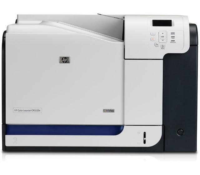
HP Color LaserJet CP3525n
Рейтинг

 Снят с производства
Тип устройства
Принтер
Технология печати
лазерная
Макс. формат
A4
Число страниц в месяц
75000
Скорость печати
A4
30
Цветность печати
цветная
Общие характеристики |
|
|---|---|
Число страниц в месяц |
75 000 |
Область применения |
средний офис |
Цветность печати |
цветная |
Размещение |
настольный |
Макс. формат |
A4 |
Тип устройства |
Принтер |
Факс |
|
Телефон |
|
Копир |
|
Печать фотографий |
|
Сканер |
|
Тип |
лазерный/светодиодный |
Технология печати |
лазерная |
Принтер |
|
Печать без полей |
|
Пигментные чернила |
|
Двусторонняя печать |
|
Количество цветов |
4 |
Макс, разрешение для ч/б печати |
|
| По X | 1 200 |
| По Y | 600 |
| По X | 600 |
Скорость ч/б печати |
|
| A4 | 30 |
Время выхода первого отпечатка |
|
| Ч/б | 11 |
Сканер |
|
Отправка изображения по e-mail |
|
Стандарт TWAIN |
|
Стандарт WIA |
|
Скорость сканирования |
|
| Цветн, | 11 |
Расходные материалы |
|
Количество картриджей |
4 |
Ресурс ч/б картриджа/тонера |
10 500 |
Ресурс цветного картриджа/тонера |
7 000 |
Печать на: |
|
| Матовой бумаге |
|
| Пленках |
|
| Этикетках |
|
| Конвертах |
|
| Глянцевой бумаге |
|
| Карточках |
|
| Рулоне |
|
| Фотобумаге |
|
| CD/DVD |
|
Плотность бумаги |
|
| Минимальная | 60 |
| Максимальная | 220 |
Факс |
|
Цветной |
|
Телефон |
|
Спикерфон |
|
Стандарт DECT |
|
Автоответчик |
|
Проводная трубка |
|
Беспроводная трубка |
|
АОН |
|
Caller ID |
|
Языки управления |
|
| PostScript |
|
| PCL 5c |
|
|
|
|
| PostScript 3 |
|
| PCL 6 |
|
| PPDS |
|
| PostScript 2 |
|
| PCL 5e |
|
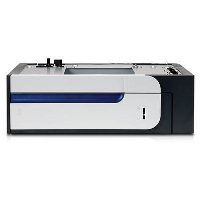
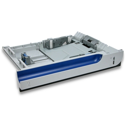
Лотки |
|
Емкость лотка ручной подачи |
100 |
Подача бумаги |
|
| Максимальная | 850 |
| Стандартная | 350 |
Вывод бумаги |
|
| Стандартный | 250 |
| Максимальный | 250 |
Финишер |
|
Брошюровщик |
|
Сортер |
|
Степлер |
|
Сортировка со сдвигом |
|
Интерфейсы |
|
Ethernet (RJ-45) |
|
Веб-интерфейс |
|
USB |
|
Wi-Fi |
|
Инфракрасный порт |
|
Устройство для чтения карт памяти |
|
FireWire (IEEE 1394) |
|
RS-232 |
|
LPT |
|
Bluetooth |
|
Версия USB |
2,0 |
Количество слотов расширения |
1 |
Количество свободных слотов расширения |
1 |
Память/Процессор |
|
Объем памяти |
256 |
Макс, объем памяти |
1 024 |
Частота процессора |
515 |
Дополнительная информация |
|
Экран |
|
Поддержка ОС |
|
| Mac OS |
|
| Windows |
|
| DOS |
|
Потребляемая мощность |
|
| При работе | 643 |
| В режиме ожидания | 35,1 |
Габариты |
|
Ширина |
513 |
Вес |
32,9 |
Высота |
358 |
Глубина |
490 |
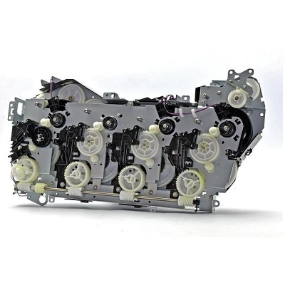
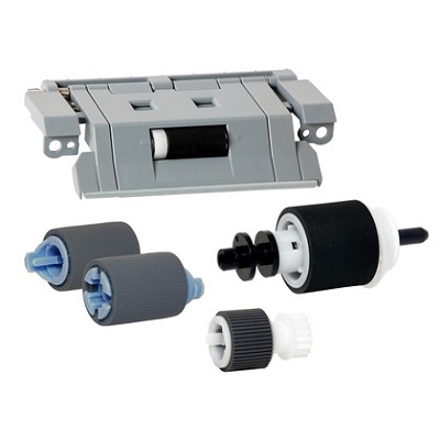
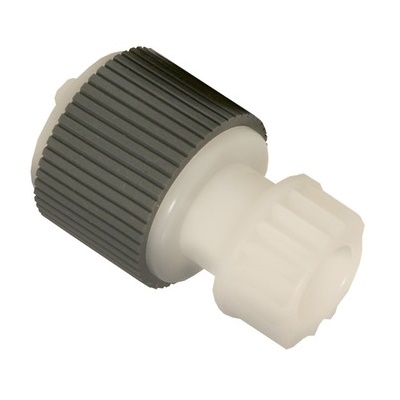
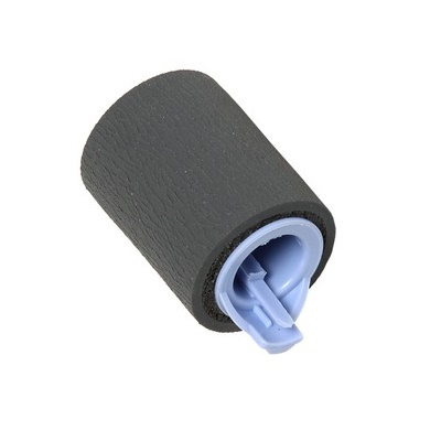
Модули
Детали Internal components 3 of 5

| Деталь: | Link, door stopper right |
| Парткод: | RC2-4916-000CN |
| Деталь: | Cover, right lower inner |
| Парткод: | RC2-5019-000CN |
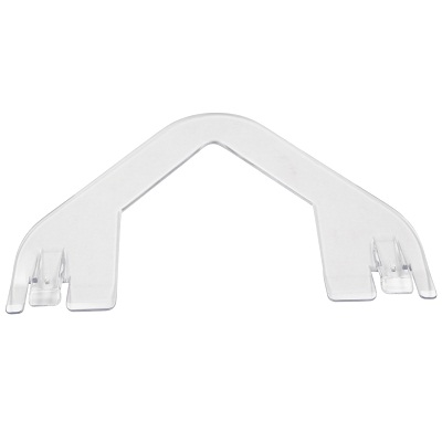
| Деталь: | Interlock link |
| Парткод: | RC2-5120-000CN |
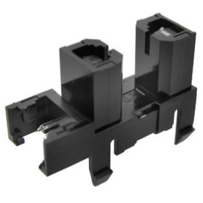
| Деталь: | Interlock switch mount |
| Парткод: | RC2-5123-000CN |
| Деталь: | Interlock link switch arm |
| Парткод: | RC2-5121-000CN |
| Деталь: | Interlock link |
| Парткод: | RC2-5119-000CN |
| Деталь: | Interlock link |
| Парткод: | RC2-5118-000CN |
| Деталь: | Switch lever |
| Парткод: | RC2-5124-000CN |
| Деталь: | SHAFT |
| Парткод: | RC2-5913-000CN |
| Деталь: | SPRING, TORSION |
| Парткод: | RC2-5934-000CN |
| Деталь: | Cartridge lock lever |
| Парткод: | RC2-5954-000CN |
| Деталь: | SPRING, TORSION |
| Парткод: | RC2-5958-000CN |
| Деталь: | Interlock link |
| Парткод: | RC2-5122-000CN |
| Деталь: | Power supply button |
| Парткод: | RL1-1947-000CN |
| Деталь: | PHOTO INTERRUPTER, TLP1243 |
| Парткод: | WG8-5696-000CN |
| Цена: | 350 ₽ |
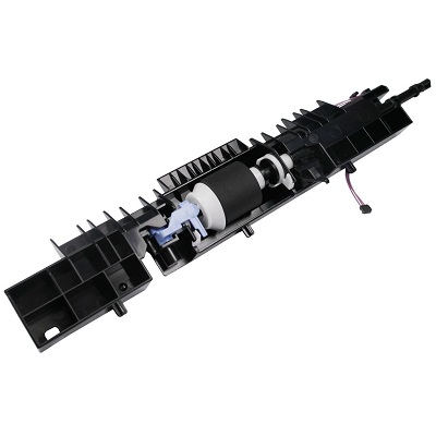
| Деталь: | Density detect sensor assembly |
| Парткод: | RM1-4953-000CN |
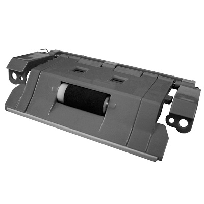
| Деталь: | Lower pick up guide assembly |
| Парткод: | RM1-4980-000CN |
| Деталь: | ITB kit |
| Парткод: | CC468-67907 |
| Деталь: | Control panel cable assembly |
| Парткод: | RM1-5743-000CN |
| Деталь: | Switch cable assembly |
| Парткод: | RM1-5718-000CN |
| Деталь: | Front cable assembly |
| Парткод: | RM1-5723-000CN |
| Деталь: | Front lock arm assembly |
| Парткод: | RM1-5532-000CN |
| Деталь: | Power supply switch assembly |
| Парткод: | RM1-5697-000CN |
| Деталь: | DOOR SWITCH ASSEMBLY |
| Парткод: | RM1-5732-000CN |
| Деталь: | SWITCH |
| Парткод: | WC4-5171-000CN |
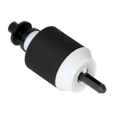
| Деталь: | Secondary transfer (T2) roller kit |
| Парткод: | CC468-67914 |
| Цена: | 3 200 ₽ |
| Деталь: | Rear lock arm assembly |
| Парткод: | RM1-5533-000CN |
| Деталь: | Duplex reverse guide kit |
| Парткод: | CC468-67913 |
| Цена: | 1 500 ₽ |
Коды ошибок
Описание
Название
HP 504A Тонер-картридж черный (5000 стр.)
HP 504X Тонер-картридж черный (10500 стр.)
Двойная упаковка черных картриджей HP-504X
HP 504A Тонер-картридж голубой
HP 504A Тонер-картридж желтый
HP 504A Тонер-картридж пурпурный
HP Емкость отработанного тонера
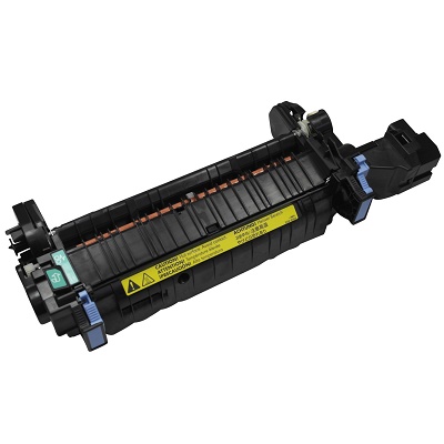
HP Печь в сборе 220V
