
HP Color LaserJet CP4520 Series
Рейтинг


Модули
Детали
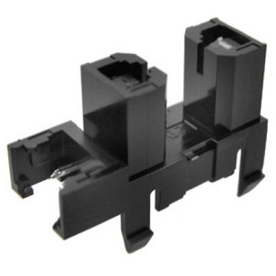
| Деталь: | CASSETTE |
| Парткод: | RM1-5928-000CN |
| Деталь: | Secondary transfer roller assembly kit (includes instructions) |
| Парткод: | CC493-67908 |
| Деталь: | Secondary transfer assembly, duplex kit (includes shaft-support clip) |
| Парткод: | CC493-67901 |
| Деталь: | Secondary transfer assembly, simplex kit (includes shaft-support clip) |
| Парткод: | CC493-67902 |
| Деталь: | COVER, REAR LOWER |
| Парткод: | RC2-5378-000CN |
| Деталь: | COVER, REAR |
| Парткод: | RC2-5379-000CN |
| Деталь: | COVER, LEFT |
| Парткод: | RC2-5393-000CN |
| Деталь: | Cover, right front, 1x500 |
| Парткод: | RC2-5356-000CN |
| Деталь: | Cover, right front, 3x500 |
| Парткод: | RC2-5357-000CN |
| Деталь: | COVER, RIGHT REAR |
| Парткод: | RC2-5380-000CN |
| Деталь: | Cover, right center |
| Парткод: | RC2-5394-000CN |
| Деталь: | Right door assembly 3x500 |
| Парткод: | RM1-5937-000CN |
| Деталь: | Right door assembly 1x500 |
| Парткод: | RM1-5936-000CN |
| Деталь: | Door, stock, 1x500 |
| Парткод: | RC2-5377-000CN |
| Деталь: | Lifter base assembly |
| Парткод: | RM1-5913-000CN |
| Деталь: | Lifter assembly |
| Парткод: | RM1-5914-000CN |
| Деталь: | Paper pickup drive assembly 3x500 |
| Парткод: | RM1-5935-000CN |
| Деталь: | Feeder PCA assembly 3x500 |
| Парткод: | RM1-5958-000CN |
| Деталь: | Paper pickup assembly |
| Парткод: | RM1-5929-000CN |
| Деталь: | CASSETTE |
| Парткод: | RM1-5928-000CN |
| Деталь: | Simplex delivery assembly kit |
| Парткод: | CC493-67918 |
| Деталь: | Duplex delivery assembly kit |
| Парткод: | CC493-67919 |
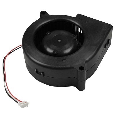
| Деталь: | FAN |
| Парткод: | RK2-2577-000CN |
| Деталь: | Cable, flexible flat, H.V.T. |
| Парткод: | RK2-2603-000CN |
| Деталь: | Contact assembly |
| Парткод: | RM1-5502-000CN |
| Деталь: | Fan cable assembly |
| Парткод: | RM1-5821-000CN |
| Деталь: | H.V. power supply cable assembly |
| Парткод: | RM1-5724-000CN |
| Деталь: | Lower main cable assembly |
| Парткод: | RM1-5801-000CN |

| Деталь: | SWITCH, PUSH |
| Парткод: | WC2-5637-000CN |
| Цена: | 340 ₽ |
| Деталь: | CONNECTING CABLE ASSEMBLY |
| Парткод: | RM1-5799-000CN |
| Деталь: | Upper main cable assembly |
| Парткод: | RM1-5800-000CN |
| Деталь: | Duplexing cable assembly, duplex |
| Парткод: | RM1-5803-000CN |
| Деталь: | Feed cable assembly |
| Парткод: | RM1-5804-000CN |
| Деталь: | Switch cable assembly |
| Парткод: | RM1-5807-000CN |
| Деталь: | CONNECTING CABLE ASSEMBLY |
| Парткод: | RM1-5811-000CN |
| Деталь: | CONNECTING CABLE ASSEMBLY |
| Парткод: | RM1-5812-000CN |
| Деталь: | Control panel cable assembly |
| Парткод: | RM1-5814-000CN |
| Деталь: | Sensor cable assembly |
| Парткод: | RM1-5815-000CN |
| Деталь: | Interlock switch cable assembly |
| Парткод: | RM1-5816-000CN |
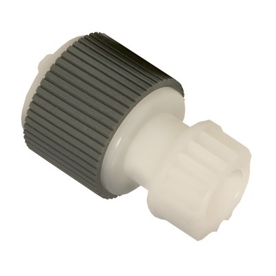
| Деталь: | Roller, paper pickup |
| Парткод: | RL1-2099-000CN |
| Цена: | 850 ₽ |
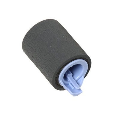
| Деталь: | PAPER FEED ROLLER |
| Парткод: | RM1-0037-020CN |
| Цена: | 70 ₽ |
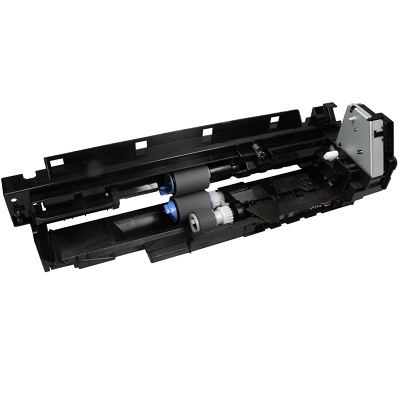
| Деталь: | Paper pickup assembly |
| Парткод: | RM1-5919-000CN |
| Цена: | 5 800 ₽ |
| Деталь: | Lifter base assembly |
| Парткод: | RM1-5913-000CN |
| Деталь: | Lifter assembly |
| Парткод: | RM1-5914-000CN |
| Деталь: | Paper pickup drive assembly, 1x500 |
| Парткод: | RM1-5934-000CN |
| Деталь: | Feeder PCA assembly, 1x500 |
| Парткод: | RM1-5854-000CN |
| Деталь: | Paper pickup assembly |
| Парткод: | RM1-5929-000CN |
| Деталь: | FRONT DOOR ASSEMBLY |
| Парткод: | RM1-5506-000CN |
| Деталь: | Pickup roller (Tray 1) kit (includes instructions) |
| Парткод: | CC49367906 |
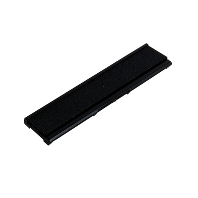
| Деталь: | Separation pad (Tray 1) |
| Парткод: | RL1-1937-000CN |
| Цена: | 1 100 ₽ |
Коды ошибок
Описание
Название
HP Комплект термозакрепления (Печка) 220V
HP Комплект для обслуживания устройства автоматической подачи документов
HP Комплект переноса
HP 647A Тонер-картридж черный (8500 стр.)
HP 649X Тонер-картридж черный (17000 стр.)
Двойная упаковка картриджей HP-649X (34000 стр.)
HP 648A Тонер-картридж голубой
HP 648A Тонер-картридж желтый
HP 648A Тонер-картридж пурпурный
HP 648A Емкость для отработанного тонера
