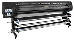
HP DesignJet L28500
Рейтинг
Снят с производства
Тип устройства
Принтер
Технология печати
термическая струйная
Макс. формат
A0
Цветность печати
цветная
Общие характеристики |
|
---|---|
Размещение |
напольный |
Макс. формат |
A0 |
Технология печати |
термическая струйная |
Тип |
струйный |
Телефон |
|
Факс |
|
Печать фотографий |
|
Копир |
|
Сканер |
|
Цветность печати |
цветная |
Тип устройства |
Принтер |
Принтер |
|
Пигментные чернила |
|
Прямая печать |
|
Система непрерывной подачи чернил |
|
Двусторонняя печать |
|
Печать без полей |
|
Мин, объем капли |
12 пл |
Макс. ширина рулона |
42 дюйм, (107 см) |
Количество цветов |
6 |
Макс, разрешение для ч/б печати |
|
По Y | 1 200 |
По X | 1 200 |
Сканер |
|
Стандарт TWAIN |
|
Слайд-адаптер |
|
Отправка изображения по e-mail |
|
Стандарт WIA |
|
Расходные материалы |
|
Количество картриджей |
6 |
Печать на: |
|
Фотобумаге |
|
Этикетках |
|
Карточках |
|
CD/DVD |
|
Конвертах |
|
Глянцевой бумаге |
![]() |
Рулоне |
![]() |
Матовой бумаге |
![]() |
Пленках |
![]() |
Факс |
|
Цветной |
|
PC Fax |
|
Телефон |
|
Caller ID |
|
АОН |
|
Беспроводная трубка |
|
Стандарт DECT |
|
Спикерфон |
|
Проводная трубка |
|
Автоответчик |
|
Языки управления |
|
PostScript 3 |
|
PCL 5c |
|
|
|
PPDS |
|
PCL 6 |
|
PCL 5e |
|
PostScript |
|
PostScript 2 |
|
Финишер |
|
Брошюровщик |
|
Сортировка со сдвигом |
|
Сортер |
|
Степлер |
|
Электронная сортировка |
|
Интерфейсы |
|
FireWire (IEEE 1394) |
|
Устройство для чтения карт памяти |
|
Веб-интерфейс |
|
RS-232 |
|
Инфракрасный порт |
|
AirPrint |
|
LPT |
|
Bluetooth |
|
Wi-Fi 802.11n |
|
Wi-Fi |
|
USB |
|
Ethernet (RJ-45) |
![]() |
Память/Процессор |
|
Объем памяти |
512 |
Дополнительная информация |
|
Работа от аккумулятора |
|
Экран |
|
Поддержка ОС |
|
DOS |
|
Linux |
|
Windows |
![]() |
Mac OS |
![]() |
Потребляемая мощность |
|
При работе | 4 200 |
В режиме ожидания | 155 |
Уровень шума |
|
При работе | 56 |
В режиме ожидания | 39 |
Габариты |
|
Ширина |
3 581 |
Глубина |
730 |
Высота |
1 377 |
Вес |
380 |
Модули
Curing Fans Assembly
Top & Back Covers
Left Cover
Printer support
Electronics Module
Dryer Assembly
Right Hand Assemblies
Center Guide and Pinchwheel Assembly
Waste Management System
Front Covers
Substrate Path Assemblies
Curing Assemblies
Vacuum Extra
Carriage Assembly
Take-Up Reel Assembly
Left Hand Assemblies
Scan-Axis Assemblies
Right Cover
Drive Roller and Media-Axis Motor
Media Entry Assemblies
Power Cabinet
Детали
Деталь: | Curing Fans Cover without Fans 104 |
Парткод: | CQ871-67042 |
Деталь: | Curing Fan SERV |
Парткод: | CH955-67062 |
Деталь: | Curing Fans Cable 104 SERV |
Парткод: | CQ871-67016 |
Деталь: | SPI Air Curtain Deflector SERV |
Парткод: | CQ869-67064 |
Деталь: | Back Covers 104 |
Парткод: | CQ871-67069 |
Деталь: | Connector Cover Right 104 SERV |
Парткод: | CQ871-67046 |
Деталь: | Rear Dryer Fan (contains 1 fan) |
Парткод: | CH955-67088 |
Деталь: | Top Cover Fan Diffusors (all fan diffusors are included) |
Парткод: | CH955-67050 |
Деталь: | CAL Top Cover Fan and Grille S |
Парткод: | CH955-67048 |
Деталь: | Top Cover 104 SERV |
Парткод: | CQ871-67038 |
Деталь: | Top Cover Fans Cable 104 SERV |
Парткод: | CQ871-67013 |
Деталь: | Drying Fans Cable 104 SERV |
Парткод: | CQ871-67020 |
Деталь: | Left Cover 104 SERV |
Парткод: | CQ871-67027 |
Деталь: | Left Trim 104 SERV |
Парткод: | CQ871-67029 |
Деталь: | Stand Hardware Kit 104 SERV |
Парткод: | CQ871-67065 |
Деталь: | Waste Management Support 104 SERV |
Парткод: | CQ871-67097 |
Деталь: | Ebox Cables 104 SERV |
Парткод: | CQ871-67003 |
Деталь: | HDD 104 SERV |
Парткод: | CQ871-67036 |
Деталь: | OMAS Controller PCA SERV |
Парткод: | CQ109-67014 |
Деталь: | Engine PCA 104 SERV |
Парткод: | CQ871-67002 |
Деталь: | Formatter PCA and Proc and HS |
Парткод: | CQ109-67020 |
Деталь: | Interconnect PCA 104 SERV |
Парткод: | CQ871-67001 |
Деталь: | EEBox Base and Cover 104 SERV |
Парткод: | CQ871-67028 |
Деталь: | PSU MR SERV |
Парткод: | CH955-67006 |
Деталь: | Extra PSU 24 V SERV |
Парткод: | CQ871-67074 |
Деталь: | PrintMech PCA 104 SERV |
Парткод: | CQ871-67030 |
Деталь: | Dryer Module 104 SERV |
Парткод: | CQ871-67043 |
Деталь: | Dryer Plastic Isolators 104 SE |
Парткод: | CQ871-67052 |
Деталь: | Dryer Grilles 104 SERV |
Парткод: | CQ871-67017 |
Деталь: | Dryer Protection 104 SERV |
Парткод: | CQ871-67051 |
Деталь: | Drying IR Sensor 104 SERV |
Парткод: | CQ871-67014 |
Деталь: | SPI Service Station SERV |
Парткод: | CQ869-67026 |
Деталь: | Bracket Right SERV |
Парткод: | Q1273-60086 |
Деталь: | Primer Valve and Tubes Assembly 10 |
Парткод: | CQ871-67055 |
Деталь: | Cables to SVS Side 104 |
Парткод: | CQ871-67081 |
Деталь: | SVC Cable + Right Switch serv |
Парткод: | Q1273-60273 |
Деталь: | Rewinder RH Module 104 SERV |
Парткод: | CQ871-67004 |
Деталь: | SVS Door Sensor Assembly with Screws |
Парткод: | CM765-67001 |
Деталь: | Vacuum Fan Assembly SERV |
Парткод: | CQ109-67022 |
Деталь: | Primer Assembly SERV |
Парткод: | Q6651-60265 |
Деталь: | Wiper Motor and Plate SERV |
Парткод: | CH955-67053 |
Деталь: | Pinchwheels Kit SERV |
Парткод: | Q6651-60066 |
Деталь: | Complete Pinchwheels 104 SERV |
Парткод: | CQ871-67023 |
Деталь: | MI Profile and Mylar 104 |
Парткод: | CQ871-67073 |
Деталь: | SPI Media Presence Sensor SERV |
Парткод: | CQ869-67021 |
Деталь: | Ml Platen 104 SERV |
Парткод: | CQ871-67072 |
Деталь: | Pinchwheel Lever Assembly 104 SERV |
Парткод: | CQ871-67057 |
Деталь: | Media Lever Sensor 104 SERV |
Парткод: | CQ871-67053 |
Деталь: | Ink Waste Management 104 SERV |
Парткод: | CQ871-67045 |
Деталь: | SPI Ink Funnels SERV |
Парткод: | CQ869-67053 |
Деталь: | SPI Drop Detector and Funnel Trans SERV |
Парткод: | CQ869-67060 |
Деталь: | SPI Drain Tube Guide SERV |
Парткод: | CQ869-67052 |
Деталь: | Window w/o Dryer 104 SERV |
Парткод: | CQ871-67039 |
Деталь: | Transparent Window SERV 42 |
Парткод: | CH955-67055 |
Деталь: | Window Locks |
Парткод: | CH955-67047 |
Деталь: | Curing Cover 104 SERV |
Парткод: | CQ871-67031 |
Деталь: | Window Lock Sensor |
Парткод: | CQ871-67005 |
Деталь: | Window Hinges (arc side) 104 |
Парткод: | CQ871-67007 |
Деталь: | Window Lock Sensor Cable 104 |
Парткод: | CQ871-67021 |
Деталь: | Print Platen Assembly 104 SERV |
Парткод: | CQ871-67037 |
Деталь: | Output Platen 104 SERV |
Парткод: | CQ871-67011 |
Деталь: | Output Roller Support and Pins |
Парткод: | CH955-67065 |
Деталь: | Input Roll Support SERV |
Парткод: | Q1273-60103 |
Деталь: | Entry Roller 104 SERV |
Парткод: | CQ871-67047 |
Деталь: | OMAS Module SERV |
Парткод: | Q6651-60270 |
Деталь: | OMAS Cable 104 |
Парткод: | CQ871-67067 |
Деталь: | TOMAS Assembly SERV |
Парткод: | CH955-67066 |
Деталь: | MI Profile and Mylar 104 |
Парткод: | CQ871-67073 |
Деталь: | Curing without Fans, Resist, IR |
Парткод: | CQ871-67041 |
Деталь: | Curing IR Sensor and Fan 104 S |
Парткод: | CQ871-67015 |
Деталь: | Curing Trims 104 SERV |
Парткод: | CQ871-67032 |
Деталь: | Curing Bracket SERV |
Парткод: | CH955-67089 |
Деталь: | Curing Thermal Switch Assembly 104 |
Парткод: | CQ871-67010 |
Деталь: | Curing Resistors 104 SERV |
Парткод: | CQ871-67022 |
Деталь: | Curing Grilles 104 SERV |
Парткод: | CQ871-67018 |
Деталь: | Curing Resistors Holders SERV |
Парткод: | CQ871-67062 |
Деталь: | Grounding Cables 104 SERV |
Парткод: | CQ871-67079 |
Деталь: | Cables to ISS Side 104 |
Парткод: | CQ871-67080 |
Деталь: | Vac Extra-Frame, Tubes, Pipes |
Парткод: | CQ871-67060 |
Деталь: | Vac Extra (Vacuum Mod with EOLA PCA) |
Парткод: | CQ871-67061 |
Деталь: | ISS PCA SERV |
Парткод: | CQ871-67082 |
Деталь: | 100 ml Synthetic Oil for Carriage |
Парткод: | CQ869-67077 |
Деталь: | Lubrication Felts Kit SERV |
Парткод: | Q6651-60081 |
Деталь: | SPI Line Sensor SERV |
Парткод: | CQ869-67062 |
Деталь: | Encoder Strip and Sensor 104 S |
Парткод: | CQ871-67012 |
Деталь: | Carriage w/o PCA,SOL,LS 104 S |
Парткод: | CQ871-67085 |
Деталь: | Cutter Assembly SERV RoHS |
Парткод: | CH955-67007 |
Деталь: | Right Carriage Bump + Others S |
Парткод: | Q6651-60341 |
Деталь: | CAL SOL Assembly SERV |
Парткод: | CH955-67101 |
Деталь: | Setup Printhead Kit SERV |
Парткод: | Q6651-60335 |
Деталь: | Carriage Flex Cables SERV |
Парткод: | CH955-67099 |
Деталь: | Carriage PCA SERV |
Парткод: | CQ109-67034 |
Деталь: | CSOL Shutter Protector SERV |
Парткод: | CH955-67083 |
Деталь: | Media Jam Sensor 104 SERV |
Парткод: | CQ871-67033 |
Деталь: | Oiler U-loaded Assembly |
Парткод: | CQ871-60297 |
Деталь: | TUR Sensor Module 104 SERV |
Парткод: | CQ871-67035 |
Деталь: | TUR RH Module 104 SERV |
Парткод: | CQ871-67034 |
Деталь: | TUR Tension Bar |
Парткод: | CQ871-67050 |
Деталь: | TUR Diverter 104 |
Парткод: | CQ871-67019 |
Деталь: | TUR LH Module 104 SERV |
Парткод: | CQ871-67048 |
Деталь: | Cartridge Trays SERV |
Парткод: | CH955-67028 |
Деталь: | ISS Down Row SERV |
Парткод: | CH955-67014 |
Деталь: | ISS Up Row SERV |
Парткод: | CH955-67013 |
Деталь: | SPI Left Bracket SERV |
Парткод: | CQ869-67009 |
Деталь: | ISS to Cartridge Cable MR SERV |
Парткод: | Q1273-60245 |
Деталь: | APS Assembly SERV 104 |
Парткод: | CQ871-67090 |
Деталь: | SOL Actuator Assembly 104 SERV |
Парткод: | CQ871-67056 |
Деталь: | ISS PCAs SERV |
Парткод: | CH955-67054 |
Деталь: | SOL Shutter Bump SERV |
Парткод: | CH955-67084 |
Деталь: | Cable Plate and Cover 104 SERV |
Парткод: | CQ871-67009 |
Деталь: | Paper Jam Sensor 104 SERV |
Парткод: | CQ871-67033 |
Деталь: | V2 Broken Bag Fixing Tools SER |
Парткод: | CH955-67111 |
Деталь: | Encoder Strip and Sensor 104 S |
Парткод: | CQ871-67012 |
Деталь: | Belt and Tensioner 104 SERV |
Парткод: | CQ871-67024 |
Деталь: | Scan Axis Motor 104 SERV |
Парткод: | CQ871-67071 |
Деталь: | SRK and TC 104 SERV |
Парткод: | CQ871-67044 |
Деталь: | SRK and Tube Clips 104 |
Парткод: | CQ871-67096 |
Деталь: | Rear and Front Tube Shelf 104 |
Парткод: | CQ871-67078 |
Деталь: | Right Cover w/o DOOR 104 SERV |
Парткод: | CQ871-67063 |
Деталь: | Right Door SERV v2 |
Парткод: | CQ871-67064 |
Деталь: | Right Trim 104 SERV |
Парткод: | CQ871-67084 |
Деталь: | FP Assembly 104 SERV |
Парткод: | CQ871-67054 |
Деталь: | QRG Holder SERV |
Парткод: | Q6651-60343 |
Деталь: | Drive Roller Encoder 104 SERV |
Парткод: | CQ871-67068 |
Деталь: | Gears Kit and Roller Brake RM |
Парткод: | CQ871-67066 |
Деталь: | Drive Roller 104 SERV |
Парткод: | CQ871-67059 |
Деталь: | Media Motor 104 SERV |
Парткод: | CQ871-67058 |
Деталь: | Rewinder Right Module |
Парткод: | CQ871-67004 |
Деталь: | 3-inch Spindle 104 SERV |
Парткод: | CQ871-67040 |
Деталь: | Spindle Hub SERV |
Парткод: | CH955-67037 |
Деталь: | Rewinder Left Module 104 SERV |
Парткод: | CQ871-67026 |
Деталь: | SPI Loading Accessory SERV |
Парткод: | CQ869-67048 |
Деталь: | SPI Loading Accessory SERV |
Парткод: | CQ871-67049 |
Деталь: | Power Cabinet 104 |
Парткод: | CQ871-67008 |
Деталь: | Heaters Control 104 SERV |
Парткод: | CQ871-67006 |
Деталь: | EOLA PCA Service Kit |
Парткод: | CQ105-67061 |
Коды ошибок
01.0:03
01.0:10
01.10:10
01.1.03
01.1.10
01.11:10
01.2:10
01.3:10
02:10
02.1:10
03:10
03.10:10
05.01:10
05:10
06.03
06.10
08.04
08:04.1
08:08
08:11
11:10
14.31:10
14.32:01
14.33:01
14.34:01
14.35:01
14.36:11
14.40:10
14.41:10
14.42:10
14.43:11
14.46:11
14.47:10
14.48:10
14.49:10
14.51:10
14.52:01
14.53:01
14.54:01
14.55:01
14.56:11
14.60:10
14.61:10
14.62:10
14.66:11
14.67:10
14.68:10
14.69:10
14.71:10
14.72:01
14.73:01
14.74:01
14.75:01
14.76:11
14.80:10
14.81:10
14.82:10
14.83:11
14.84:11
14.85:11
14.86:11
14.87:10
14.88:10
14.89:10
15.01:00
15.02:00
15.03:00
15.04:00
15.05:00
15.06:00
15.08:00
15.09:11
15.15:11
15.20:01
16.01:00
16.02:00
16.03:00
16.04:00
16.05:00
16.06:00
16.08:00
16.09:00
16.11:00
16.20:11
16.21:10
17.0:11
17.1:11
17.2:11
17.3:11
17.4:11
21:03
21:13
21.2:10
21.3:10
21.4:03
21.5:03
23:10
24.02:00
24:03
24.03:00
24:10
24:11
24.1:11
26.0:01
26.1:01
26:14
26.2:01
26.3:01
26.4:01
26.5:01
27:01
27.1:01
27:14
27.2:01
27.3:01
27.4:01
27.5:01
27.6:01
29:01
32:01
32:01.1
32:01.2
32:01.9
32:02
41:03
42:03
42:10
42.10:11
42.11:10
43:11
43.11:11
43.12:11
43.13:10
43.14:10
43.2:11
43.3:10
43.4:10
44:10
44.1:01
44:11
44.2:01
44.3:01
44.4:01
45:03
45:10
46:03
46:10
4.63:11
50.10:11
50.1:10
50:14
50.2:10
50.3:11
52:01
52:10
53.1:10
53.1:11
54:10
55:10
56:01
56:10
58:01
58:10
58.1:10
58.2:10
59.1:09
59.2:00
61:10
63:05
65:04
74:01
77:04
78.1:04
78.2:01
79:03
79:04
81:01
81:03
82:01
85:03
86:01
87:01
94:01
94:02
94:10
98:03
XX.n:YZ.m
Описание
Error code: | 01.0:03 |
Description: | Error impact I2C channel. |
Causes: | The Main PCA has failed to respond. |
Remedy: | • Switch the Power OFF from the back of the Printer and disconnect the Power cord. Reconnect the power cord and power On the Printer. • If the System Error continues, replace the Sausalito PCI PCA . |
Error code: | 01.0:10 |
Description: | Engine PCA electronics error. The main Engine PCA component is not responding |
Causes: | Engine PCA damaged or wrongly connected. Connector on the formatter damaged (very low probability). |
Remedy: | Call agent: • Restart the printer. Service engineer: 1. Replace the engine PCA board (95% probabilities). See Engine PCA. 2. If the problem persist, replace the formatter PCA board (very low probability). See Formatter PCA. |
Error code: | 01.10:10 |
Description: | PrintMech PCA is faulty |
Causes: | The PrintMech PCA is not disabling sine-wave converters when requested. |
Remedy: | 1. Switch the power off at the rear of the printer, wait briefly, then switch it back on again. 2. Replace the PrintMech PCA. |
Error code: | 01.1.03 |
Description: | PrintMech PCA electronics error |
Causes: | The PrintMech PCA has failed to respond. |
Remedy: | Switch the power off at the rear of the printer, wait briefly, then switch it back on again. |
Error code: | 01.1.10 |
Description: | PrintMech PCA hardware failure |
Causes: | PrintMech PCA hardware failure. |
Remedy: | 1. Switch the power off at the rear of the printer, wait briefly, then switch it back on again. 2. Replace the PrintMech PCA. |
Error code: | 01.11:10 |
Description: | PrintMech PCA is faulty |
Causes: | The PrintMech PCA is not enabling sine-wave converters when requested. |
Remedy: | 1. Switch the power off at the rear of the printer, wait briefly, then switch it back on again. 2. Replace the PrintMech PCA. |
Error code: | 01.2:10 |
Description: | ISS1 PCA problem |
Causes: | Printmech to ISS1 PCA cable Main PSU to Printmech PCA cable ISS PCA Printmech PCA. |
Remedy: | Call agent: 1. Remove/Replace Ink Cartridges. 2. Restart the printer. Service engineer: 1. Reseat/Replace Printmech to ISS1 PCA cable. 2. Reseat/Replace Main PSU to Printmech cable. 3. Replace ISS PCA. See Ink supply station PCAs. 4. Replace PrintMech PCA.. See PrintMech PCA. |
Error code: | 01.3:10 |
Description: | IISS2 PCA problem |
Causes: | ISS1 to ISS2 Cable ISS PCA. |
Remedy: | Call agent: 1. Remove/Replace Ink Cartridges. 2. Restart the printer. Service engineer: 1. Reseat/Replace ISS1 to ISS2 PCA cable. 2. Replace ISS PCA. See Ink supply station PCAs |
Error code: | 02:10 |
Description: | Carriage PCA communication failure. Trailing Cables, Printhead, Encoder Strip |
Causes: | Mechanical Carriage error. |
Remedy: | 1. Remove covers and check that the Trailing cables are connected from the Main PCA or from the Carriage PCA. If any cable is disconnected then reconnect it, and power on the printer again to check whether the error message has disappeared. 2. Go to Support Menu, see Entering the Extended Support Menu for service engineers and perform 2.1 Carriage Servo, see 2.1 Carriage servo to check that the error has disappeared. 3. Replace the Encoder Strip, see Encoder Strip and run the Carriage Servo diagnostics to see if the error has disappeared. 4. Replace the Carriage, see Carriage and Belt. • Carriage assembly w/belt (24) • CQ890-67002 • Carriage assembly w/belt (36) • CQ893-67011 5. No calibrations needed, but the PMK 1 should be reset, see 3.4 PMK1. 6. Replace the Main PCA, see Main PCA. • Main PCA Basic: CQ891-67003 • Main PCA Pro: CQ890-67023 |
Error code: | 02.1:10 |
Description: | Carriage PCA electronics error. The main components in the carriage PCA are not responding |
Causes: | Carriage PCA damaged. Power not reaching the carriage PCA. Tariling cable (data) damaged. |
Remedy: | Call agent: • Restart the printer. Service engineer: 1. Change the Carriage PCA (80% probability). We recommend to change ONLY this part on the 1st visit, and if it doesn`t work follow the troubleshooting below. See Carriage PCA. 2. If the issue is not fixed: 2.1. Check that the trailing cable is well connected and not damaged. 2.2. If the power LED (add picture) is ON, the power is reaching the carriage PCA --> the power trailing cable is OK. 2.1.1. Change the Engine PCA. See Engine PCA. 2.1.2. If the Engine PCA does not fix the issue, change the trailing cable. 2.3. If the power LED is OFF, the power is not reaching the carriage: 2.3.1. Check that the POWER trailing cable is not damaged and is well connected to the Carriage and the Interconnect PCA. 2.3.2. Disconnect the trailing cable from the Interconnect PCA and check with a multimeter at the interconnect PCA that there is power in the connector. 2.3.2.1. If there is power at the interconnect PCA connector, then, change the trailing cable. 2.3.2.2. If there is no power at the interconnect PCA connector, then, change the interconnect PCA. See Interconnect PCA. |
Error code: | 03:10 |
Description: | Power distribution failure |
Causes: | Power distribution failure |
Remedy: | • Turn the power off at the rear of the printer and disconnect the power cord. Reconnect the power cord and turn on the printer. • If the Power Supply Unit`s blue LED is on, replace the PrintMech PCA. If not, replace the Power Supply Unit. |
Error code: | 03.10:10 |
Description: | Extra 24 V PSU failure |
Causes: | Extra 24 V PSU failure. |
Remedy: | 1. Switch the power off at the rear of the printer. 2. Disconnect all drying fans (not the array, the fans one by one). 3. Switch the printer on. 4. If the error persists, check that Secondary PSU cables are properly connected to PrintMech PCA and Main PSU. 5. If the error persists, replace the Extra 24 V PSU. 6. Connect the fans one by one until the error returns. Use the diagnostic test for the fans; it should switch them all on. 7. Replace the drying fan that caused the error. 8. Make sure that you test all of them: more than one may be faulty. |
Error code: | 05.01:10 |
Description: | Formatter CPU fan stopped or burnt out |
Causes: | Formatter CPU fan stopped or burnt out. |
Remedy: | 1. Switch the power off at the rear of the printer, wait briefly, then switch it back on again. 2. Replace the Formatter. |
Error code: | 05:10 |
Description: | Formatter communication failure with ISS |
Causes: | Formatter communication failure with ISS |
Remedy: | • Turn the power off at the rear of the printer and disconnect the power cord. Reconnect the power cord and turn on the printer. • Check that the Formatter to PrintMech PCA cable is correctly connected. • If the system error persists, replace the Formatter Formatter. |
Error code: | 06.03 |
Description: | Main NVM communication failure |
Causes: | The Main NVM is not responding. |
Remedy: | 1. Switch the power off at the rear of the printer, wait briefly, then switch it back on again. 2. Replace the Hard Disk Drive. |
Error code: | 06.10 |
Description: | Main NVM communication failure |
Causes: | The Main NVM is not responding. |
Remedy: | 1. Switch the power off at the rear of the printer, wait briefly, then switch it back on again. 2. Replace the Hard Disk Drive. |
Error code: | 08.04 |
Description: | The Front Panel watchdog timer has expired |
Causes: | The Front Panel watchdog timer has expired. |
Remedy: | 1. Switch the power off at the rear of the printer, wait briefly, then switch it back on again. 2. Upgrade the firmware. |
Error code: | 08:04.1 |
Description: | ASSERT in Front Panel code |
Causes: | ASSERT in Front Panel code. |
Remedy: | 1. Press Enter and continue. 2. Update the firmware. |
Error code: | 08:08 |
Description: | A feature on the Touch Control Panel hangs or will not function (copy,scan etc) |
Causes: | ASSERT in Front Panel code. |
Remedy: | 1. Turn off the product and turn on again, and check to see if the error remains. 2. Upgrade the firmware For more information, see Appendix B: Emergency firmware upgrade with USB flash drive 3. Escalate the issue. |
Error code: | 08:11 |
Description: | Front Panel communication failure |
Causes: | Front Panel communication failure |
Remedy: | • Turn the power off at the rear of the printer and disconnect the power cord. Reconnect the power cord and turn on the printer. • See What to do if the front panel is blank. |
Error code: | 11:10 |
Description: | Trailing Cable does not seem to be connected |
Causes: | Trailing Cable does not seem to be connected |
Remedy: | • Check that the Trailing Cable is not damaged. • Check that the Trailing Cable is correctly connected to the Carriage PCA, Interconnect PCA and Main PCA. • Replace the Ink Supply Tubes and Trailing Cable. NOTE: If the Ink Supply Tubes are to be replaced, the Ink Cartridges need to be checked beforehand to see if they are capable of purging the new tubes. If they are not, new Ink Cartridges must also be sent with the parts to be replaced. To check the Ink Cartridges, go to Check ink supplies. |
Error code: | 14.31:10 |
Description: | Pinch Power regulator V null and no fault |
Causes: | Pinch Power regulator V null and no fault. |
Remedy: | 1. Switch the power off at the rear of the printer, wait briefly, then switch it back on again. 2. Run the Monitoring Sine-waves and Resistances diagnostic test. 3. Replace the control cables to the sine-wave converter. |
Error code: | 14.32:01 |
Description: | Pinch Power regulator V null and faulty |
Causes: | Pinch Power regulator V null and faulty. |
Remedy: | 1. Switch the power off at the rear of the printer, wait briefly, then switch it back on again. 2. Run the Monitoring Sine-waves and Resistances diagnostic test. 3. Check the Residual Current Circuit Breakers. 4. Check the input voltage. |
Error code: | 14.33:01 |
Description: | Pinch Power regulator V lower than 140 |
Causes: | Pinch Power regulator V lower than 140. |
Remedy: | 1. Switch the power off at the rear of the printer, wait briefly, then switch it back on again. 2. Check the input voltage. 3. Run the Monitoring Sine-waves and Resistances diagnostic test. |
Error code: | 14.34:01 |
Description: | Pinch Power regulator V lower than 180 |
Causes: | Pinch Power regulator V lower than 180. |
Remedy: | 1. Switch the power off at the rear of the printer, wait briefly, then switch it back on again. 2. Check the input voltage. 3. Run the Monitoring Sine-waves and Resistances diagnostic test. |
Error code: | 14.35:01 |
Description: | Pinch Power regulator V higher than Vmax |
Causes: | Pinch Power regulator V higher than Vmax. |
Remedy: | 1. Switch the power off at the rear of the printer, wait briefly, then switch it back on again. 2. Check the input voltage. 3. Run the Monitoring Sine-waves and Resistances diagnostic test. |
Error code: | 14.36:11 |
Description: | Pinch Power regulator V could not be read |
Causes: | Pinch Power regulator V could not be read. |
Remedy: | 1. Switch the power off at the rear of the printer, wait briefly, then switch it back on again. 2. Check the input cables. 3. Replace the control cables to the sine-wave converters. |
Error code: | 14.40:10 |
Description: | Pinch Power regulator current not null |
Causes: | Pinch Power regulator current not null. |
Remedy: | 1. Switch the power off at the rear of the printer, wait briefly, then switch it back on again. 2. Replace the sine-wave converter. 3. Run the Monitoring Sine-waves and Resistances diagnostic test. |
Error code: | 14.41:10 |
Description: | Pinch Power regulator current too high |
Causes: | Pinch Power regulator current too high. |
Remedy: | 1. Switch the power off at the rear of the printer, wait briefly, then switch it back on again. 2. Run the Monitoring Sine-waves and Resistances diagnostic test. 3. Check heaters with a tester and replace heaters if necessary (short-circuit). 4. Replace the sine-wave converter. |
Error code: | 14.42:10 |
Description: | Pinch Power regulator short-circuit |
Causes: | Pinch Power regulator short-circuit. |
Remedy: | 1. Switch the power off at the rear of the printer, wait briefly, then switch it back on again. 2. Run the Monitoring Sine-waves and Resistances diagnostic test. 3. Check heaters with a tester and replace heaters if necessary. 4. Replace the sine-wave converter. |
Error code: | 14.43:11 |
Description: | Pinch Power Regulator open circuit |
Causes: | Pinch Power Regulator open circuit. If the error appears in the middle of a print and recovers after cooling down, it could be caused by an abnormal increase in the drying module temperature leading one of the thermal switches to open. See System Errors 15.03:00 and 15.20:01 for more information. |
Remedy: | 1. Switch the power off at the rear of the printer, wait briefly, then switch it back on again. 2. Run the Monitoring Sine-waves and Resistances diagnostic test. 3. Check cable connections and heaters with a tester. 4. Check the drying module: • Ensure that the heaters do not touch the metal covers at the sides, close to the thermal switches. • Remove the side covers. Ensure that the connections to the thermal switches are strong; tighten the nuts if necessary. In addition, ensure the cables are not peeled or in bad condition. 5. Replace the drying heaters if any of the above applies. Other possible causes: • The room temperature is too high or is outside the operational specification of the printer. Make sure there are no external sources of heat, such as strong lights, direct sunlight, or heaters. • This system error may be caused by a setting in the RIP being used by the customer. If the ¡¥Minimum Drying Power¡¦ setting in the RIP is too high, this can cause the system error to be triggered. Set the Minimum Drying Power to 0, and check whether the error remains. • Check that there are no obstructions on any of the cooling fans: Dryer, Curing, Top Cover Fans, Rear Fans. • Check that all the fans are functioning correctly. Check that the cables of the fans are not damaged and are connected. Replace any fans if required: Top cover fans. Drying Fans. Curing Fans. See System Errors 15.03:00 and 15.20:01 for more information. |
Error code: | 14.46:11 |
Description: | Pinch Power regulator R out of range |
Causes: | Pinch Power regulator R out of range. |
Remedy: | 1. Switch the power off at the rear of the printer, wait briefly, then switch it back on again. 2. Run the Monitoring Sine-waves and Resistances diagnostic test. 3. Check cable connections. 4. Check heaters with a tester and replace heaters if necessary. 5. Replace the sine-wave converter. |
Error code: | 14.47:10 |
Description: | Pinch Power regulator OverTemp |
Causes: | Pinch Power regulator OverTemp. |
Remedy: | 1. Switch the power off at the rear of the printer, wait briefly, then switch it back on again. 2. Run the Monitoring Sine-waves and Resistances diagnostic test. 3. Check cable connections. 4. Check that the input voltage is within specifications. 5. Replace the sine-wave converter. |
Error code: | 14.48:10 |
Description: | Pinch Power regulator overvoltage or short-circuit |
Causes: | Pinch Power regulator overvoltage or short-circuit. |
Remedy: | 1. Switch the power off at the rear of the printer, wait briefly, then switch it back on again. 2. Run the Monitoring Sine-waves and Resistances diagnostic test. 3. Check cable connections. 4. Check that the input voltage is within specifications. 5. Replace the sine-wave converter. |
Error code: | 14.49:10 |
Description: | Pinch sine-wave converter failure |
Causes: | Pinch sine-wave converter failure. |
Remedy: | 1. Switch the power off at the rear of the printer, wait briefly, then switch it back on again. 2. Replace the sine-wave converter. |
Error code: | 14.51:10 |
Description: | Overdrive power regulator V null and no fault |
Causes: | Overdrive power regulator V null and no fault. |
Remedy: | 1. Switch the power off at the rear of the printer, wait briefly, then switch it back on again. 2. Run the Monitoring Sine-waves and Resistances diagnostic test. 3. Replace the control cables to the sine-wave converter. |
Error code: | 14.52:01 |
Description: | Overdrive power regulator V null and fault |
Causes: | Overdrive power regulator V null and fault. |
Remedy: | 1. Switch the power off at the rear of the printer, wait briefly, then switch it back on again. 2. Run the Monitoring Sine-waves and Resistances diagnostic test. 3. Check the Residual Current Circuit Breakers. 4. Check the input voltage. |
Error code: | 14.53:01 |
Description: | Overdrive power regulator V lower than 140 |
Causes: | Overdrive power regulator V lower than 140. |
Remedy: | 1. Switch the power off at the rear of the printer, wait briefly, then switch it back on again. 2. Check the input voltage. 3. Run the Monitoring Sine-waves and Resistances diagnostic test. |
Error code: | 14.54:01 |
Description: | Overdrive power regulator V lower than 180 |
Causes: | Overdrive power regulator V lower than 180. |
Remedy: | 1. Switch the power off at the rear of the printer, wait briefly, then switch it back on again. 2. Check the input voltage. 3. Run the Monitoring Sine-waves and Resistances diagnostic test. |
Error code: | 14.55:01 |
Description: | Overdrive power regulator V higher than Vmax |
Causes: | Overdrive power regulator V higher than Vmax. |
Remedy: | 1. Switch the power off at the rear of the printer, wait briefly, then switch it back on again. 2. Check the input voltage. 3. Run the Monitoring Sine-waves and Resistances diagnostic test. |
Error code: | 14.56:11 |
Description: | Overdrive power regulator V could not be read |
Causes: | Overdrive power regulator V could not be read. |
Remedy: | 1. Switch the power off at the rear of the printer, wait briefly, then switch it back on again. 2. Check cable connections. 3. Replace the control cables to the sine-wave converter. |
Error code: | 14.60:10 |
Description: | Overdrive power regulator current not null |
Causes: | Overdrive power regulator current not null. |
Remedy: | 1. Switch the power off at the rear of the printer, wait briefly, then switch it back on again. 2. Replace the sine-wave converter. 3. Run the Monitoring Sine-waves and Resistances diagnostic test. |
Error code: | 14.61:10 |
Description: | Overdrive power regulator current too high |
Causes: | Overdrive power regulator current too high. |
Remedy: | 1. Switch the power off at the rear of the printer, wait briefly, then switch it back on again. 2. Run the Monitoring Sine-waves and Resistances diagnostic test. 3. Check heaters with tester and replace heaters if necessary (short-circuit). 4. Replace the sine-wave converter. |
Error code: | 14.62:10 |
Description: | Overdrive power regulator short-circuit |
Causes: | Overdrive power regulator short-circuit. |
Remedy: | 1. Switch the power off at the rear of the printer, wait briefly, then switch it back on again. 2. Run the Monitoring Sine-waves and Resistances diagnostic test. 3. Check heaters with tester and replace heaters if necessary. 4. Replace the sine-wave converter. |
Error code: | 14.66:11 |
Description: | Overdrive power regulator R out of range |
Causes: | Overdrive power regulator R out of range. |
Remedy: | 1. Switch the power off at the rear of the printer, wait briefly, then switch it back on again. 2. Run the Monitoring Sine-waves and Resistances diagnostic test. 3. Check cable connections. 4. Check heaters with tester and replace heaters if necessary. 5. Replace the sine-wave converter. |
Error code: | 14.67:10 |
Description: | Overdrive power regulator OverTemp |
Causes: | Overdrive power regulator OverTemp. |
Remedy: | 1. Switch the power off at the rear of the printer, wait briefly, then switch it back on again. 2. Run the Monitoring Sine-waves and Resistances diagnostic test. 3. Check cable connections. 4. Check that the input voltage is within specifications. 5. Replace the sine-wave converter. |
Error code: | 14.68:10 |
Description: | Overdrive power regulator overvoltage or short-circuit |
Causes: | Overdrive power regulator overvoltage or short-circuit. |
Remedy: | 1. Switch the power off at the rear of the printer, wait briefly, then switch it back on again. 2. Run the Monitoring Sine-waves and Resistances diagnostic test. 3. Check cable connections. 4. Check that the input voltage is within specifications. 5. Replace the sine-wave converter. |
Error code: | 14.69:10 |
Description: | Overdrive sine-wave error |
Causes: | Overdrive power sine-wave error. |
Remedy: | 1. Switch the power off at the rear of the printer, wait briefly, then switch it back on again. 2. Replace the sine-wave converter. |
Error code: | 14.71:10 |
Description: | Curing power regulator V null and no fault |
Causes: | Curing power regulator V null and no fault. |
Remedy: | 1. Switch the power off at the rear of the printer, wait briefly, then switch it back on again. 2. Run the Monitoring Sine-waves and Resistances diagnostic test. 3. Replace the control cables to the sine-wave converter. |
Error code: | 14.72:01 |
Description: | Curing power regulator V null and fault |
Causes: | Curing power regulator V null and fault. |
Remedy: | 1. Switch the power off at the rear of the printer, wait briefly, then switch it back on again. 2. Run the Monitoring Sine-waves and Resistances diagnostic test. 3. Check the Resident Current Circuit Breakers. 4. Check the input voltage. |
Error code: | 14.73:01 |
Description: | Curing power regulator V lower than 60: V lower than 60 |
Causes: | Heater Control AC Input (RCCB, AC Voltage Outlet, AC Power Cord) Heater Control. |
Remedy: | Call agent: 1. Check that both Residual Circuit Breakers (RCCBs) are Powered and ON. 2. Check/Reseat both Power Cords. Service engineer: 1. Check AC Voltage at customer`s site (180-264Vac). 2. Reseat/Replace cables to Heater Control`s AC input. 3. Replace the Heater Control. |
Error code: | 14.74:01 |
Description: | Curing power regulator V lower than 140 |
Causes: | V lower than 140 |
Remedy: | Service engineer: 1. Run Service "Curing system monitor". 2. Check the input voltage. |
Error code: | 14.75:01 |
Description: | Curing power regulator V bigger than Vmax |
Causes: | V bigger than Vmax |
Remedy: | 1. Check the input voltage. 2. Run Service "Curing system monitor". |
Error code: | 14.76:11 |
Description: | Curing power regulator V could not be read |
Causes: | Curing Control PCA Cable to Heater Control. |
Remedy: | Service engineer: 1. Run Service "Curing system monitor". 2. Reseat/Replace Curing Control PCA Cable to Heater Control. |
Error code: | 14.80:10 |
Description: | Curing power regulator current not null |
Causes: | Heater Control. |
Remedy: | Service engineer: 1. Run Service "Curing system monitor". 2. Replace the Heater Control. |
Error code: | 14.81:10 |
Description: | Curing power regulator current too high |
Causes: | Heaters, Heater Control. |
Remedy: | Service engineer: 1. Run Service "Curing system monitor". 2. Check heaters with a tester and replace heaters if necessary (shortcut). 3. Replace the Heater Control. |
Error code: | 14.82:10 |
Description: | Curing power regulator shortcut |
Causes: | Heaters, Heater Control. |
Remedy: | Service engineer: 1. Run Service "Curing system monitor". 2. Check heaters with a tester and replace heaters if necessary (shortcut). 3. Replace the Heater Control. |
Error code: | 14.83:11 |
Description: | Curing power regulator open circuit |
Causes: | Heater Control to Curing Power Interconnect PCA Cable. Curing Power Interconnect PCA Curing Cable. Curing Resistor. |
Remedy: | Service engineer: 1. Run Service "Curing system monitor". 2. Reseat/Replace the Heater Control to Curing Power Interconnect PCA Cables. 3. Reseat/Replace Curing Power Interconnect PCA Curing Cable. 4. Reseat/Replace all Curing Resistors connectors. |
Error code: | 14.84:11 |
Description: | Curing power regulator Rtotal is nominal1 |
Causes: | Curing power regulator Rtotal is nominal1. |
Remedy: | 1. Switch the power off at the rear of the printer, wait briefly, then switch it back on again. 2. Check intermediate heater connections to see if one of the resistors is disconnected. 3. Replace the curing heaters. |
Error code: | 14.85:11 |
Description: | Curing power regulator Rtotal is nominal2 |
Causes: | Curing power regulator Rtotal is nominal2. |
Remedy: | 1. Switch the power off at the rear of the printer, wait briefly, then switch it back on again. 2. Check intermediate heater connections to see if one of the resistors is disconnected. 3. Replace the curing heaters. |
Error code: | 14.86:11 |
Description: | Curing power regulator R out of range |
Causes: | Curing power regulator R out of range. |
Remedy: | 1. Switch the power off at the rear of the printer, wait briefly, then switch it back on again. 2. Run Monitoring Sine-waves and Resistances diagnostic test. 3. Check cable connections. 4. Check heaters with tester and replace heaters if necessary. 5. Replace the sine-wave converter. |
Error code: | 14.87:10 |
Description: | Curing power regulator OverTemp |
Causes: | Power regulator OverTemp. |
Remedy: | Service engineer: 1. Run Service "Curing system monitor". 2. If the SE appears frequently, replace the Heater Control. |
Error code: | 14.88:10 |
Description: | Curing power regulator overvoltage or shortcut |
Causes: | Regulator overvoltage or shortcut. |
Remedy: | Service engineer: 1. Run Service "Curing system monitor". 2. Check resistor module values, If they are ok, check installation. |
Error code: | 14.89:10 |
Description: | Curing power regulator relay damaged |
Causes: | Heater Control. |
Remedy: | Service engineer: 1. Run Service "Curing system monitor". 2. Replace de Heater Control. |
Error code: | 15.01:00 |
Description: | Drying system warn-up timed out |
Causes: | The drying system is unable to warm up in the pre-defined amount of time (to 45°C for standby and normally 55°C or 60°C for printing). |
Remedy: | 1. Check that the room temperature is within the printer`s operating specifications; it should be higher than 15¢XC for printer operation. If it is too low, increase the room temperature. 2. Check that the input voltage is within the printer¡¦s operating specifications: see the Site Preparation Guide. 3. Check whether the substrate loaded on the printer is too transparent or reflective for the IR sensor to detect the surface temperature. You can check this by loading another type of substrate. 4. Check whether the Dryer IR sensor is dirty and requires cleaning. Observe all safety precautions while working in the area of the heaters. 5. Check that the position of the IR sensor is correct. If it is pointing to a position other than the substrate this will cause an error. 6. Perform the Heating IR sensor diagnostic check, to check the values being detected by the IR sensor. Replace the Dryer IR sensor if required. 7. Replace the cables from the PrintMech PCA to the connection box. 8. Replace the PrintMech PCA. |
Error code: | 15.02:00 |
Description: | Drying system cool-down timed out |
Causes: | The drying system is unable to cool down in the pre-defined amount of time. |
Remedy: | 1. Check that the room temperature is within the printer¡¦s operating specifications. If necessary, remove external sources of heat, such as strong lights, direct sunlight, or heaters. 2. This system error can occur if the ¡¥Minimum Drying Power¡¦ setting in the RIP is too high. Set the Minimum Drying Power to 0, and check whether the error repeats. 3. Check there are no obstructions on any of the cooling fans: Dryer, Curing, Top Cover Fans, Rear Fans. 4. Check that all the fans are functioning correctly. Check that the cables of the fans are undamaged and connected. Replace any fans if required: Top Cover Fans. Drying Fans. Curing Fans. |
Error code: | 15.03:00 |
Description: | Drying system temperature too high |
Causes: | The drying system has exceeded the upper temperature limit. |
Remedy: | 1. Check that the room temperature is within the printer¡¦s operating specifications. If necessary, remove external sources of heat, such as strong lights, direct sunlight, or heaters. 2. This system error can occur if the ¡¥Minimum Drying Power¡¦ setting in the RIP is too high. Set the Minimum Drying Power to 0, and check whether the error repeats. 3. Check there are no obstructions on any of the cooling fans: Dryer, Curing, Top Cover Fans, Rear Fans. 4. Check that all the fans are functioning correctly. Check that the cables of the fans are undamaged and connected. Replace any fans if required: Top Cover Fans. Drying Fans. Curing Fans. |
Error code: | 15.04:00 |
Description: | Drying system temperature too low |
Causes: | The drying system has fallen below the lower temperature limit (below 15°C). |
Remedy: | 1. Check that the room temperature is within the printer`s operating specifications; it should be higher than 15¢XC for printer operation. If it is too low, increase the room temperature. 2. Check whether the Dryer IR sensor is dirty and requires cleaning. Observe all safety precautions while working in the area of the heaters. 3. Check that the position of the IR sensor is correct. If it is pointing to a position other than the substrate this will cause an error. 4. Perform the Heating IR sensor diagnostic check, to check the values being detected by the IR sensor. Replace the Dryer IR sensor if required. 5. Replace the cables from the PrintMech PCA to the connection box. 6. Replace the PrintMech PCA. |
Error code: | 15.05:00 |
Description: | Problem with the drying system Temperature Sensor |
Causes: | Signal error detected with the drying system Temperature Sensor. |
Remedy: | 1. Check that the room temperature is within the printer¡¦s operating specifications. If necessary, remove external sources of heat, such as strong lights, direct sunlight, or heaters. 2. This system error can occur if the ¡¥Minimum Drying Power¡¦ setting in the RIP is too high. Set the Minimum Drying Power to 0, and check whether the error repeats. 3. Check there are no obstructions on any of the cooling fans: Dryer, Curing, Top Cover Fans, Rear Fans. 4. Check that all the fans are functioning correctly. Check that the cables of the fans are undamaged and connected. Replace any fans if required: Top Cover Fans. Drying Fans. Curing Fans. 5. Check whether the Dryer IR sensor is dirty and requires cleaning. Observe all safety precautions while working in the area of the heaters. 6. Check that the position of the IR sensor is correct. If it is pointing to a position other than the substrate this will cause an error. 7. Perform the Heating IR sensor diagnostic check, to check the values being detected by the IR sensor. Replace the Dryer IR sensor if required. 8. Replace the cables from the PrintMech PCA to the connection box. 9. Replace the PrintMech PCA. |
Error code: | 15.06:00 |
Description: | Temperature error detected |
Causes: | There is a mismatch between the temperature detected by the Drying IR Sensor and the amount of electrical power the drying system is receiving. |
Remedy: | 1. The ink density may be too high, check the User`s Guide for the recommended ink density levels. 2. Check that the input voltage is within the printer¡¦s operating specifications: see the Site Preparation Guide. 3. Check whether the substrate loaded on the printer is too transparent or reflective for the IR sensor to detect the surface temperature. You can check this by loading another type of substrate. 4. Check whether the Dryer IR sensor is dirty and requires cleaning. Observe all safety precautions while working in the area of the heaters. 5. Check that the position of the IR sensor is correct. If it is pointing to a position other than the substrate this will cause an error. 6. Perform the Heating IR sensor diagnostic check, to check the values being detected by the IR sensor. Replace the Dryer IR sensor if required. 7. Replace the cables from the PrintMech PCA to the connection box. 8. Replace the PrintMech PCA. |
Error code: | 15.08:00 |
Description: | Heating fans array not connected |
Causes: | Heating fans array not connected. |
Remedy: | Check the cable connections to the heating fans. |
Error code: | 15.09:11 |
Description: | Heating fan fault |
Causes: | Heating fan fault. |
Remedy: | 1. Switch the power off at the rear of the printer, wait briefly, then switch it back on again. 2. Run the Diagnostic test and confirm which fans are rotating. 3. If none of the fans is working, replace the PrintMech PCA. 4. Replace the cable from the PrintMech PCA to the fans. 5. If at least one of the fans is working, ensure it is connected to the array cable. 6. Replace the non-rotating fans. |
Error code: | 15.15:11 |
Description: | Drying fan short-circuit |
Causes: | One or more drying fans have been short-circuited. |
Remedy: | 1. Disconnect all drying fans except one from their own connectors. 2. Run the Fans diagnostic test. 3. If the error appears, the short-circuited fan is probably the connected one. Disconnect, connect another one and continue to next step. 4. If the error does not appear, connect the fans one by one until it does. The failing fan is the last one connected. Disconnect the failing fan and finish the test with all the fans in the array, just in case there is more than one with the problem. 5. Replace the failing fans. 6. Replace the drying fans cable. |
Error code: | 15.20:01 |
Description: | Minimum drying power has been automatically adjusted |
Causes: | This error will appear only in the Service Plot. When the drying zone temperature increases in an uncontrolled manner and for no apparent reason, the firmware will automatically adjust the minimum drying power. When this happens, this error will be logged and visible in the Service Plot. |
Remedy: | 1. Check that the room temperature is within the printer¡¦s operating specifications. If necessary, remove external sources of heat, such as strong lights, direct sunlight, or heaters. 2. This system error can occur if the ¡¥Minimum Drying Power¡¦ setting in the RIP is too high. Set the Minimum Drying Power to 0, and check whether the error repeats. 3. Check there are no obstructions on any of the cooling fans: Dryer, Curing, Top Cover Fans, Rear Fans. 4. Check that all the fans are functioning correctly. Check that the cables of the fans are undamaged and connected. Replace any fans if required: Top Cover Fans. Drying Fans. Curing Fans. |
Error code: | 16.01:00 |
Description: | Curing System unable to warm up in the pre-defined amount of time |
Causes: | Ambient temperature below 15oC. Low AC Voltage. Fans (Curing, Air Curtain, PZ). Curing Resistors. Curing Temperature Sensor. Curing Pressure Sensor. |
Remedy: | 1. Check if the environmental ambient temperature is low. Check the surrounding temperature is within the printer`s operating specifications; it should be higher than 15C for printer operation. If this is the case, increase the ambient temperature of the printer`s location. 2. Check if the input voltage is outside the range of specifications for printing, see the Site Preparation Guide. 3. Run Service "Curing system monitor". 4. Check all Fans (Curing, Air Curtain, PZ), all spinning and no obstruction. 5. Reseat/Replace Curing Resistors. 6. Reseat/Replace Curing Temperature Sensors. 7. Reseat/Replace Curing Pressure Sensor. |
Error code: | 16.02:00 |
Description: | Curing system: cool down timeout |
Causes: | Ambient temperature above 30C Fans (Curing, Air Curtain, PZ). |
Remedy: | Service engineer: 1. The environmental ambient temperature is too hot or is outside the operational specification of the printer. Make sure there are no external sources of heat, such as strong lights, direct sunlight, heaters etc. 2. Check all Fans (Curing, Air Curtain, PZ), are rotating, and unobstructed. |
Error code: | 16.03:00 |
Description: | Curing system: high temperature error |
Causes: | Ambient temperature above 30oC, Fans (Curing, Air Curtain, PZ), Curing Resistors, Curing Temperature Sensor, Curing Pressure Sensor. |
Remedy: | 1. The environmental ambient temperature is too hot or is outside the operational specification of the printer. Make sure there are no external sources of heat, such as strong lights, direct sunlight, heaters etc. 2. Run Service "Curing system monitor”. 3. Check all Fans (Curing, Air Curtain, PZ), are rotating, and unobstructed. 4. Reseat/Replace Curing Resistors. 5. Reseat/Replace Curing Temperature Sensors. 6. Reseat/Replace Curing Pressure Sensor. |
Error code: | 16.04:00 |
Description: | Curing system: low temperature error |
Causes: | Ambient temperature below 15oC, Low AC Voltage Fans (Curing, Air Curtain, PZ), Curing Resistors, Curing Temperature Sensor, Curing Pressure Sensor. |
Remedy: | 1. Check if the environmental ambient temperature is low. Check the surrounding temperature is within the printer`s operating specifications; it should be higher than 15C for printer operation. If this is the case, increase the ambient temperature of the printer`s location. 2. Check the input voltage is outside the range of specifications for printing, see the Site Preparation Guide. 3. Run Service "Curing system monitor. 4. Check all Fans (Curing, Air Curtain, PZ), are rotating, and unobstructed. 5. Reseat/Replace Curing Resistors. 6. Reseat/Replace Curing Temperature Sensors. 7. Reseat/Replace Curing Pressure Sensor. |
Error code: | 16.05:00 |
Description: | Curing system: temperature sensor error |
Causes: | Curing Control PCA Temperature Sensors Cable Temp. Sensors. |
Remedy: | Call agent: • Restart the printer. Service engineer: 1. Run Service "Curing system monitor". 2. Reseat/replace Curing Control PCA Temperature Sensors Cable. 3. Reseat/replace Temp. Sensors. |
Error code: | 16.06:00 |
Description: | Temperature error detected |
Causes: | There is a mismatch between the temperature detected by the Curing IR Sensor and the amount of electrical power the curing system is receiving. |
Remedy: | 1. The ink density may be too high, check the User`s Guide for the recommended ink density levels. 2. Check that the input voltage is within the printer¡¦s operating specifications: see the Site Preparation Guide. 3. Check whether the substrate loaded on the printer is too transparent or reflective for the IR sensor to detect the surface temperature. You can check this by loading another type of substrate. 4. Check whether the Curing IR sensor is dirty and requires cleaning. Observe all safety precautions while working in the area of the heaters. 5. Check for an obstacle blocking the IR sensor¡¦s view. Ensure that the IR sensor is correctly installed on the printer, with no interference in the infrared light path, and that it is pointing to the substrate. 6. Perform the Curing IR sensor diagnostic check, to check the values being detected by the IR sensor. Replace the Curing IR sensor if required. 7. Replace the cables from the PrintMech PCA to the connection box. 8. Replace the PrintMech PCA. |
Error code: | 16.08:00 |
Description: | Curing fans array 1 not connected |
Causes: | The array 1 of curing system fans is not connected. |
Remedy: | Check the cable connections to the curing fans. |
Error code: | 16.09:00 |
Description: | Curing fan array 1 fault |
Causes: | Curing fan array 1 fault. |
Remedy: | 1. Run the Diagnostic test and confirm which fans are rotating. 2. If none of the fans is working, replace the PrintMech PCA. 3. Replace the cable from the PrintMech to the fans. 4. If at least one of the fans is working, ensure it is connected to the array 1 cable. 5. Replace the non-rotating fans. |
Error code: | 16.11:00 |
Description: | Curing fans array 2 not connected |
Causes: | Curing fans array 2 not connected. |
Remedy: | Check the cable connections to the curing fans array 2. |
Error code: | 16.20:11 |
Description: | IR sensor curing fan not connected |
Causes: | IR sensor curing fan not connected. |
Remedy: | Check the cable connections to the IR sensor. |
Error code: | 16.21:10 |
Description: | Curing fan array 2 fault |
Causes: | Curing fan array 2 fault. |
Remedy: | 1. Switch the power off at the rear of the printer, wait briefly, then switch it back on again. 2. Run the diagnostic test and confirm which fans are rotating. 3. If none of the fans is working, replace the PrintMech PCA. 4. Replace the cable from the PrintMech PCA to the fans. 5. If at least one of the fans is working, ensure that it is connected to the array 2 cable. 6. Replace the non-rotating fans. |
Error code: | 17.0:11 |
Description: | PrintMech to Interconnect Power cable does not seem to be connected |
Causes: | The power cable from Printmech to Interconnect PCA has a problem. |
Remedy: | Call agent: • Restart the printer. Service engineer: 1. Check that the PrintMech to Interconnect Power cable is not damaged. 2. Check that the PrintMech to Interconnect Power cable is correctly connected to the PrintMech PCA and the Interconnect PCA. 3. Replace the PrintMech to Interconnect Power cable (which is included in the Electronics Module Cable Kit). |
Error code: | 17.1:11 |
Description: | PrintMech to Interconnect Data 1 cable does not seem to be connected |
Causes: | PrintMech to Interconnect Data 1 cable does not seem to be connected |
Remedy: | • Check that the PrintMech to Interconnect Data 1 cable is not damaged. • Check that the PrintMech to Interconnect Data 1 cable is correctly connected to the PrintMech PCA and the Interconnect PCA. • Replace the PrintMech to Interconnect Data 1 cable (which is included in the Electronics Module Cable Kit). |
Error code: | 17.2:11 |
Description: | PrintMech to Interconnect Data 2 cable does not seem to be connected |
Causes: | PrintMech to Interconnect Data 2 cable does not seem to be connected |
Remedy: | • Check that the PrintMech to Interconnect Data 2 cable is not damaged. • Check that the PrintMech to Interconnect Data 2 cable is correctly connected to the PrintMech PCA and the Interconnect PCA. • Replace the PrintMech to Interconnect Data 2 cable (which is included in the Electronics Module Cable Kit). |
Error code: | 17.3:11 |
Description: | Main PCA to PrintMech Black 1 cable does not seem to be connected |
Causes: | Main PCA to PrintMech Black 1 cable is damaged Main PCA damaged. |
Remedy: | Call agent: • Restart the printer. Service engineer: 1. Check that the Main PCA to PrintMech Black 2 cable is not damaged. 2. Check that the Main PCA to PrintMech Black 2 cable is correctly connected to the Main PCA and the PrintMech PCA. 3. Replace the Main PCA to PrintMech Black 2 cable. |
Error code: | 17.4:11 |
Description: | Main PCA to PrintMech White 2 cable does not seem to be connected |
Causes: | Main PCA to PrintMech White 2 cable is damaged Main PCA damaged. |
Remedy: | Call agent: • Restart the printer. Service engineer: 1. Check that the Main PCA to PrintMech White 2 cable is not damaged. 2. Check that the Main PCA to PrintMech White 2 cable is correctly connected to the Main PCA and the PrintMech PCA. 3. Replace the Main PCA to PrintMech White 2 cable. |
Error code: | 21:03 |
Description: | Service Station electrical current limit |
Causes: | Electrical current limit. |
Remedy: | Call agent: • Make sure that the Service Station path is clear. Remove any visible obstacles restricting the movement of the Service Station. Service engineer: • If the System Error continues, replace the Service Station. See Service station. |
Error code: | 21:13 |
Description: | Problem with the Service Station. SVS jam |
Causes: | SVS jam. |
Remedy: | Call agent: 1. Switch the Power OFF from the back of the Printer. Power the Printer back On. 2. Make sure that the Service Station path is clear. Remove any visible obstacles (e.g. screws, plastic parts, etc.) restricting the movement of the Service Station. 3. Switch the Power OFF from the back of the Printer, remove the Printhead Maintenance Cartridge, and check if there`s any obstacle along the MC path. 4. Check that the MC is not finished, and the web advance is working properly. 5. Check the spit roller and rack engage mechanisms. Service engineer: 1. If the error happens after printing for several hours and is cleared after power cycling, small damage in the encoder can cause the print carriage to lose its position little by little. The same effect could be produced by aerosol, ink or oil stain on the encoder. Clean (or replace) the encoder strip if it is dirty (or damaged). 2. If the System Error continues, replace the Service Station. See Service station. |
Error code: | 21.2:10 |
Description: | Web Wipe servo shutdown |
Causes: | Web Wipe motor is damaged Interconnect PCA is damaged (very low probability) PrintMech PCA is damaged. |
Remedy: | Call agent: 1. Switch the power off at the rear of the printer, manually pull the Printhead Maintenance Cartridge to the front position and switch the printer on again. 2. Switch the power off at the rear of the printer and remove the Printhead Maintenance Cartridge. Switch the printer on again. If the error is cleared, replace the Printhead Maintenance Cartridge. Service engineer: 1. Revise that Web Wipe cable is correctly connected to Interconnect PCA. 2. Replace the Web Wipe Motor. |
Error code: | 21.3:10 |
Description: | Electrical fault in rack engage motor |
Causes: | Web Wipe motor has a problem |
Remedy: | Call agent: 1. Switch the power off at the rear of the printer, manually pull the Printhead Maintenance Cartridge to the front position and switch the printer on again. 2. Switch the power off at the rear of the printer and remove the Printhead Maintenance Cartridge. Switch the printer on again. If the error is cleared, replace the Printhead Maintenance Cartridge. Service engineer: 1. Replace the Web Wipe Motor. 2. Replace the PrintMech PCA. See PrintMech PCA. |
Error code: | 21.4:03 |
Description: | Electrical warm in rack engage motor Electrical current limit in rackEngage motor |
Causes: | Electrical fault detected. Possible causes are cable, motor or driver. |
Remedy: | Call agent: 1. Switch the power off at the rear of the printer, manually pull the Printhead Maintenance Cartridge to the front position and switch the printer on again. 2. Switch the power off at the rear of the printer and remove the Printhead Maintenance Cartridge. Switch the printer on again. If the error is cleared, replace the Printhead Maintenance Cartridge. Service engineer: • Replace the Web Wipe. |
Error code: | 21.5:03 |
Description: | Service Station rack cannot be disengaged |
Causes: | Web Wipe motor is damaged or blocked |
Remedy: | Call agent: 1. Switch the power off at the rear of the printer, manually pull the Printhead Maintenance Cartridge to the front position and switch the printer on again. 2. Switch the power off at the rear of the printer and remove the Printhead Maintenance Cartridge. Switch the printer on again. If the error is cleared, replace the Printhead Maintenance Cartridge. Service engineer: • Replace the Web Wipe Motor. |
Error code: | 23:10 |
Description: | The system has problems to pressurize or to depressurize |
Causes: | APS Cable Air Tubes APS Assembly. |
Remedy: | Call agent: • Restart the printer. Service engineer: 1. Check that the APS cable is not damaged and is correctly connected to the PrintMech PCA. 2. Check that the air tubes are properly connected and are not kinked or pinched. 3. Check that there is no supply with air leakage. 4. Replace the APS Assembly. See APS assembly. |
Error code: | 24.02:00 |
Description: | The firmware has detected that there is no connection to the array of Top Covers Fans |
Causes: | Top cover fans cable (array) damaged or not connected to Interconnect PCA. Interconnect PCA damaged (very low probability). PrintMech PCA damaged (very low probability). |
Remedy: | Call agent: • Restart the printer. Service engineer: 1. Check the Top Cover fan cable, by the right arch, is connected to the Interconnect PCA, and that it is not damaged. 2. If all the cables from the Interconnect PCA to the fans are connected, replace the PrintMech PCA. |
Error code: | 24:03 |
Description: | Ink Supply Tubes purge failure |
Causes: | Purge failure. |
Remedy: | 1. Ensure that the dummy printheads are correctly installed and purge the Ink Supply Tubes again. 2. If the problem persists; replace the Setup Printhead Kit. |
Error code: | 24.03:00 |
Description: | The firmware has detected that one or more of the Top Covers Fans is not working |
Causes: | One or more of the top cover fans can be damaged. Top cover fan cable connector (from array) can be damaged (very low probability) . |
Remedy: | Call agent: • Restart the printer. Service engineer: 1. Revise if there are some Top cover fan that is not runing. 2. If none of the fans are working, this would indicate a failure with the PrintMech, or the cables from the Interconnect PCA: a. Check the cables from the Interconnect PCA. b. If all the cables from the PrintMech PCA to the fans are connected, replace the Printmech PCA. c. If message still present replace the Interconnect PCA. 3. If at least one of the fans is working, check if the failed fans are connected to the array, if it is connected replace the failed fan (Top Cover Fans). 4. If the error is not cleared, check all the cables from the failed fan to the PrintMech. |
Error code: | 24:10 |
Description: | A broken bag has been detected in one of the Ink Cartridges |
Causes: | A broken bag has been detected in one of the Ink Cartridges |
Remedy: | • Press Down + Cancel to see which cartridges have a broken bag. Remove the affected cartridges, shake each one three times within 2 seconds through a distance of about 40 cm, and check whether the cartridge air tower is contaminated with ink. If at least one cartridge is contaminated, replace the Ink Supply Tubes and Trailing Cable Ink Supply Tubes and Trailing Cable. NOTE: If the Ink Supply Tubes are to be replaced, the Ink Cartridges need to be checked beforehand to see if they are capable of purging the new tubes. If they are not, new Ink Cartridges must also be sent with the parts to be replaced. To check the Ink Cartridges, see Check ink supplies. • If no cartridge seems contaminated, follow the broken bag recovery procedure for more information Recover broken bag. |
Error code: | 24:11 |
Description: | PrintMech to ISS Top cable does not seem to be connected |
Causes: | PrintMech to ISS top cable not connected. |
Remedy: | Call agent: • Restart the printer. Service engineer: 1. Check that the PrintMech to ISS Top cable is correctly connected. 2. Replace the PrintMech to ISS Top cable. 3. Replace the ISS Top PCA. |
Error code: | 24.1:11 |
Description: | ISS Top to ISS Bottom cable does not seem to be connected |
Causes: | ISS1 to ISS2 cable not connected. |
Remedy: | Call agent: • Restart the printer. Service engineer: 1. Check that the PrintMech to ISS Top cable is correctly connected. 2. Check that the ISS Top to ISS Bottom cable is correctly connected. 3. Replace ISS Top to ISS Bottom cable. 4. Replace the ISS Bottom PCA. |
Error code: | 26.0:01 |
Description: | Bad contact detected in ISS slot 0 floater |
Causes: | Bad contact detected in ISS slot 0 floater |
Remedy: | • Remove the Magenta Ink Cartridge and reinstall it into the printer. • Replace the Magenta Ink Cartridge. • Check that the ISS to Cartridge cable (Magenta Ink Cartridge) is not damaged and is correctly connected to the Ink Supply Tubes PCA. • Replace the ISS to Cartridge cable (Magenta Ink Cartridge) ISS to Cartridge Cables. |
Error code: | 26.1:01 |
Description: | Bad contact detected in ISS slot 1 floater |
Causes: | Bad contact detected in ISS slot 1 floater |
Remedy: | • Remove the Light Magenta Ink Cartridge and reinstall it into the printer. • Replace the Light Magenta Ink Cartridge. • Check that the ISS to Cartridge cable (Light Magenta Ink Cartridge) is not damaged and is correctly connected to the Ink Supply Tubes PCA. • Replace the ISS to Cartridge cable (Light Magenta Ink Cartridge) ISS to Cartridge Cables. |
Error code: | 26:14 |
Description: | A wrong Ink Cartridge has been detected. |
Causes: | A wrong ink cartridge has been detected. |
Remedy: | • Remove the Ink Cartridges and check that they are the correct ones for this Printer. • Check that the Printer has the latest Firmware version. If not, update the Firmware to the latest version. • Replace the Ink Cartridges. |
Error code: | 26.2:01 |
Description: | Bad contact detected in ISS slot 2 floater |
Causes: | Bad contact detected in ISS slot 2 floater |
Remedy: | • Remove the Photo Black Ink Cartridge and reinstall it into the printer. • Replace the Photo Black Ink Cartridge. • Check that the ISS to Cartridge cable (Photo Black Ink Cartridge) is not damaged and is correctly connected to the Ink Supply Tubes PCA. • Replace the ISS to Cartridge cable (Photo Black Ink Cartridge) ISS to Cartridge Cables. |
Error code: | 26.3:01 |
Description: | Bad contact detected in ISS slot 3 floater |
Causes: | Bad contact detected in ISS slot 3 floater |
Remedy: | • Remove the Matte Black Ink Cartridge and reinstall it into the printer. • Replace the Matte Black Ink Cartridge. • Check that the ISS to Cartridge cable (Matte Black Ink Cartridge) is not damaged and is correctly connected to the Ink Supply Tubes PCA. • Replace the ISS to Cartridge cable (Matte Black Ink Cartridge) ISS to Cartridge Cables. |
Error code: | 26.4:01 |
Description: | Bad contact detected in ISS slot 4 floater |
Causes: | Bad contact detected in ISS slot 4 floater |
Remedy: | • Remove the Yellow Ink Cartridge and reinstall it into the printer. • Replace the Yellow Ink Cartridge. • Check that the ISS to Cartridge cable (Yellow Ink Cartridge) is not damaged and is correctly connected to the Ink Supply Tubes PCA. • Replace the ISS to Cartridge cable (Yellow Ink Cartridge) ISS to Cartridge Cables. |
Error code: | 26.5:01 |
Description: | Bad contact detected in ISS slot 5 floater |
Causes: | Bad contact detected in ISS slot 5 floater |
Remedy: | • Remove the Light Cyan Ink Cartridge and reinstall it into the printer. • Replace the Light Cyan Ink Cartridge. • Check that the ISS to Cartridge cable (Light Cyan Ink Cartridge) is not damaged and is correctly connected to the Ink Supply Tubes PCA. • Replace the ISS to Cartridge cable (Light Cyan Ink Cartridge) ISS to Cartridge Cables. |
Error code: | 27:01 |
Description: | Too many nozzles out detected (Advisory) |
Causes: | Calibration may have failed due to a high number of blocked nozzles in a printhead. |
Remedy: | Call agent: 1. Print the gNozzle healthh diagnostic print from the service menu. If printhead shows many nozzles out, replace the printhead. 2. If printhead doesnft show too many nozzles out, run gdrop detector calibrationh. Service engineer: • If printhead doesnft have too many nozzles out and gdrop detection calibrationh doesnft help, replace the drop detector. |
Error code: | 27.1:01 |
Description: | Error due to a high number of nozzles out in printhead slot 1 |
Causes: | High number of nozzles out in printhead slot 1. |
Remedy: | Service engineer: 1. Clean all the printheads and check their status. 2. Replace the printhead. |
Error code: | 27:14 |
Description: | An incorrect Printhead has been detected. |
Causes: | Printhead failure. |
Remedy: | Call agent: 1. Remove the Printheads and check that they are the correct ones for this Printer. 2. Check that the Printer has the latest Firmware version, if not, update the firmware to the latest version. 3. Replace the Printheads. |
Error code: | 27.2:01 |
Description: | Error due to a high number of nozzles out in printhead slot 2 |
Causes: | High number of nozzles out in printhead slot 2. |
Remedy: | Service engineer: 1. Clean all the printheads and check their status. 2. Replace the printhead. |
Error code: | 27.3:01 |
Description: | Error due to a high number of nozzles out in printhead slot 3 |
Causes: | High number of nozzles out in printhead slot 3. |
Remedy: | Service engineer: 1. Clean all the printheads and check their status. 2. Replace the printhead. |
Error code: | 27.4:01 |
Description: | Error due to a high number of nozzles out in printhead slot 4 |
Causes: | High number of nozzles out in printhead slot 4. |
Remedy: | Service engineer: 1. Clean all the printheads and check their status. 2. Replace the printhead. |
Error code: | 27.5:01 |
Description: | Error due to a high number of nozzles out in printhead slot 5 |
Causes: | High number of nozzles out in printhead slot 5. |
Remedy: | Service engineer: 1. Clean all the printheads and check their status. 2. Replace the printhead. |
Error code: | 27.6:01 |
Description: | Error due to a high number of nozzles out in printhead slot 6 |
Causes: | High number of nozzles out in printhead slot 6. |
Remedy: | Service engineer: 1. Clean all the printheads and check their status. 2. Replace the printhead. |
Error code: | 29:01 |
Description: | Maintenance cartridge badly inserted |
Causes: | Maintenance cartridge badly inserted. |
Remedy: | Call agent: 1. Open the Print Head cleaning cartridge door on the right-hand side of the printer, reinsert the MC and close the door . 2. If the problem persists, replace the printhead cleaning cartridge. |
Error code: | 32:01 |
Description: | TUR disconnected while printing |
Causes: | Take-up Reel disconnected from Interconnect PCA. Take-Up Reel damaged. Interconnect PCA damaged (very low probability). |
Remedy: | Call agent: • The take-up reel is disconnected. If you want to use the take-up reel, turn off the printer and ensure that all take-up reel cables are connected (sensor cables, printer cable). If you do not want to use it, you may need to unload the substrate manually from the take-up reel. Remember to cut the substrate first, either manually or by using the Form feed and cut option in the front panel`s Substrate menu. Service engineer: 1. Revise the Take-up Reel connections. 2. Replace the Take-up Reel RH module. See Take-up reel motor. |
Error code: | 32:01.1 |
Description: | TUR early media jam |
Causes: | This system error happens when there is a small amount of substrate printed (less than 79 inches long), and the Take Up Reel sensor detects that the tension bar is (incorrectly) at the bottom of its path, even though the spindle motor has been rotating for more than 3 seconds. The most likely cause of this error is that the user has forgotten to set the switch direction or tape the substrate to the spindle core. |
Remedy: | 1. Check that the substrate is attached to the Take-Up Reel. 2. Check that the winding direction switch is in the correct position. 3. If needed, use the Take-Up Reel arrow keys to wind the substrate before resuming printing. 4. To resume printing, press OK. |
Error code: | 32:01.2 |
Description: | Take up reel Media Jam |
Causes: | The tension bar has stayed in one of its sensor trigger positions for more than 8 seconds. |
Remedy: | 1. Check that the substrate is attached to the Take-Up Reel. 2. Check that the winding direction switch is in the correct position. 3. Check that nothing is blocking the movement of the tension bar. 4. Ensure that the substrate is following the correct path along the tension bar and diverter bar. |
Error code: | 32:01.9 |
Description: | Take-up Reel (TUR) disabled because paper was removed unexpectedly |
Causes: | The Take-Up Reel has been disabled because the substrate was unexpectedly removed from it. |
Remedy: | Remove all paper from the printer and reinstall the TUR. |
Error code: | 32:02 |
Description: | TUR disconnected while printer was powered off. This message is shown during initialization of the printer; it warns that the Take-Up Reel has been disconnected while the printer was off (previously the Take-Up Reel was enabled by Front Panel) |
Causes: | Take-up Reel disconnected from Interconnect PCA. Take-Up Reel damaged. Interconnect PCA damaged (very low probability). |
Remedy: | • The take-up reel is disconnected. If you want to use the take-up reel, turn off the printer and ensure that all take-up reel cables are connected (sensor cables, printer cable). If you do not want to use it, you may need to unload the substrate manually from the take-up reel. Remember to cut the substrate first, either manually or by using the Form feed and cut option in the front panel`s Substrate menu. Service engineer: 1. Revise the Take-up Reel conections. 2. Replace the Take-up Reel RH module. See Take-up reel motor |
Error code: | 41:03 |
Description: | Electrical current limit: Electrical current limit in paper motor Electrical warm: Electrical warm in paper motor |
Causes: | The Media-axis motor has a failure. |
Remedy: | Call agent: • Open the Window and check for any visible obstacles restricting the movement of the Drive Roller. If there is a wrinkled mass of paper inside the paper path, lift the Pinchwheels and clear the obstruction. Service engineer: • Replace the Media-Axis Motor. |
Error code: | 42:03 |
Description: | Scan-Axis motor electrical current limit |
Causes: | Media jam Scan Axis motor damaged. |
Remedy: | Call agent: 1. Switch the power off from the rear of the printer and disconnect the power cord. Reconnect the power cord and power on the printer. 2. Open the Window and check for any visible obstacles restricting the movement of the carriage. If there is a wrinkled mass of substrate inside the printer, clear the substrate jam using instructions provided in the User Guide. Service engineer: • Replace the Scan Axis Motor. See Scan-axis motor |
Error code: | 42:10 |
Description: | Scan axis motor fault detected |
Causes: | Scan axis failure. |
Remedy: | Service engineer: • Replace the Scan-Axis Motor. |
Error code: | 42.10:11 |
Description: | Scan-Axis Motor cooling fan not connected |
Causes: | The Scan-Axis Motor cooling fan is not connected. |
Remedy: | 1. Perform the Scan Axis Service test. 2. Check that the Scan-Axis Motor fan cable is not damaged and is correctly connected to the PrintMech PCA. 3. Replace the Scan-Axis Motor fan. 4. Replace the PrintMech PCA. |
Error code: | 42.11:10 |
Description: | Scan-Axis Motor cooling fan fault |
Causes: | Scan-Axis Motor cooling fan fault. It is connected, but when applying PWM it does not turn. |
Remedy: | 1. Switch the power off at the rear of the printer, wait briefly, then switch it back on again. 2. Replace the Scan-Axis Motor Fan. |
Error code: | 43:11 |
Description: | Vacuum fan not connected |
Causes: | Vacuum fan not connected. |
Remedy: | Call agent: • Restart the printer. Service engineer: 1. Check the cable connections between the Mini Interconnect PCA and Eola SVS side. 2. Replace Eolas. 3. Replace the Mini Interconnect PCA. |
Error code: | 43.11:11 |
Description: | Vacuum Fan 2 or 3 not connected |
Causes: | Vacuum Fan 2 or 3 is not connected. |
Remedy: | 1. Check cable connections between the PrintMech PCA and Eolas IDS side. 2. Replace Eolas. 3. Replace the PrintMech PCA. |
Error code: | 43.12:11 |
Description: | Vacuum Fan 2 or 3 stopped |
Causes: | Vacuum Fan 2 or 3 has stopped. |
Remedy: | 1. Check the cable connections between Eolas and Vacuum Fans IDS side. 2. Replace the Vacuum Fans. |
Error code: | 43.13:10 |
Description: | Vacuum Fan 2 or 3 overcurrent |
Causes: | Vacuum Fan 2 or 3 overcurrent. |
Remedy: | 1. Switch the power off at the rear of the printer, wait briefly, then switch it back on again. 2. Replace the Vacuum Fans IDS side. |
Error code: | 43.14:10 |
Description: | Vacuum Fan 2 or 3 low performance |
Causes: | Vacuum Fan 2 or 3 is not performing adequately. |
Remedy: | 1. Switch the power off at the rear of the printer, wait briefly, then switch it back on again. 2. Replace the Vacuum Fans IDS side. |
Error code: | 43.2:11 |
Description: | A Vacuum Fan Stopped: Vacuum Fan Stopped |
Causes: | A Vacuum Fan is not connected. The Vacuum Fan cable is damaged. Eola PCA is damaged. PrintMech PCA is damaged (very low probability). |
Remedy: | Call agent: • Restart the printer. Service engineer: 1. Check the cable connections between Vacumm fans and EOLA PCA. 2. Replace the Vacuum Fan. See Vacuum fan. |
Error code: | 43.3:10 |
Description: | VacuumFan Over current: Vacuum Fan Overcurrent, SVS side |
Causes: | Vacuum fan failure. |
Remedy: | Call agent: • Switch the power off at the rear of the printer, wait briefly, then switch it back on again. Service engineer: • Replace the Vacuum Fan SVS side. |
Error code: | 43.4:10 |
Description: | VacuumFan Low Performance: Vacuum Fan is not working at the desired performance., SVS side |
Causes: | Vacuum fan failure. |
Remedy: | Call agent: • Switch the power off at the rear of the printer, wait briefly, then switch it back on again. Service engineer: • Replace the Vacuum Fan SVS side. |
Error code: | 44:10 |
Description: | Aerosol Fan Fault |
Causes: | Aerosol Fan damaged Interconnect PCA damaged (very low probability) PrintMech PCA (very low probability). |
Remedy: | Call agent: • Restart the printer. Service engineer: 1. Check that the Aerosol Fan cable is correctly connected to the Interconnect PCA. 2. Check that the cables going from the Interconnect PCA to the PrintMech PCA are correctly connected. 3. Replace the Aerosol Fan. See Aerosol fan assembly. 4. If the previous action did not work then, replace the PrintMech PCA. See PrintMech PCA. |
Error code: | 44.1:01 |
Description: | Waste Management cable not connected |
Causes: | The waste management system cable is disconnected. |
Remedy: | 1. Check the connections between the Waste Management PCA and the printer. 2. Check the connections to the Interconnect PCA. 3. Check that the cable of the waste management system is correctly connected to the connector at the EBOX (this check can be done by the customer). This is the most probable cause. 4. Replace the Waste Management module (this part can be changed by the customer). 5. Check that the cable from the EBOX to the Interconnect PCA is correctly connected. 6. Check that the cables going from the Interconnect PCA to the PrintMech PCA are correctly connected. 7. Replace the Interconnect PCA. 8. Replace the PrintMech PCA. |
Error code: | 44:11 |
Description: | Aerosol Fan not connected. |
Causes: | The Aerosol Fan is disconnected. |
Remedy: | • Check that the Aerosol Fan cable is not damaged and is correctly connected to the Interconnect PCA. • Replace the Aerosol Fan . |
Error code: | 44.2:01 |
Description: | Waste management switch open |
Causes: | At least one of the switches of the waste management sub-assembly is in open status. |
Remedy: | 1. Check that the aerosol filter door is correctly closed (this can be done by the customer). 2. Check that the waste management ink tube is correctly inserted in the waste management subassembly (this can be done by the customer). 3. Replace the Waste Management module (this part can be changed by the customer). This is the most likely solution. 4. Check that the cable of the waste management system is correctly connected to the connector at the EBOX (this check can be done by the customer). 5. Check that the cable from the EBOX to the Interconnect PCA is correctly connected. 6. Check that the cables going from the Interconnect PCA to the PrintMech PCA are correctly connected. 7. Replace the Interconnect PCA. 8. Replace the PrintMech PCA. |
Error code: | 44.3:01 |
Description: | Waste management cable short-circuited |
Causes: | There is a short-circuit in the waste management system cable, and maybe also in the Interconnect PCA. |
Remedy: | 1. Replace the Waste Management module (this part can be changed by the customer). This is the most likely solution. 2. Check that the cable of the waste management system is correctly connected to the connector at the EBOX (this check can be done by the customer). 3. Check that the cable from the EBOX to the Interconnect PCA is correctly connected. 4. Check that the cables going from the Interconnect PCA to the PrintMech PCA are correctly connected. 5. Replace the Interconnect PCA. 6. Replace the PrintMech PCA. |
Error code: | 44.4:01 |
Description: | Problem in the waste management feedback signal |
Causes: | There is a problem with the feedback signal from the waste management system. |
Remedy: | 1. Check that the cable of the waste management system is correctly connected to the connector at the EBOX (which can be done by the customer). This is the most probable failure. 2. Replace the Waste Management module (which can be done by the customer). 3. Check that the cable from the EBOX to the Interconnect PCA is correctly connected. 4. Check that the cables going from the Interconnect PCA to the PrintMech PCA are correctly connected. 5. Replace the Interconnect PCA. 6. Replace the PrintMech PCA. |
Error code: | 45:03 |
Description: | Rewinder servo shutdown |
Causes: | Rewinder motor disconected. Rewinder motror damaged. Rewinder motor cable damaged. Interconnect PCA damaged (very low probability). PrintMech PCA damaged (very low probability). |
Remedy: | Call agent: 1. Switch the power off at the rear of the printer, wait briefly, then switch it back on again. 2. pen the Window and check for any visible obstacles restricting the movement of the Drive Roller. If there is a wrinkled mass of substrate inside the substrate path, lift the Pinch Wheels and clear the obstruction. Service engineer: 1. Revise the Rewinder motor cable connections to Interconnect PCA. 2. Replace the Rewinder Motor. See Rewinder. 3. If the previous action did not work then, replace the PrintMech PCA. 4. If the previous action did not work then, replace the Interconnect PCA. |
Error code: | 45:10 |
Description: | Rewinder motor failure. Main PCA |
Causes: | Rewinder fault. |
Remedy: | Remote troubleshooting (call agent) 1. Switch off the printer, and disconnect the power cord. Reconnect the power cord and power on the printer. 2. The call agent should arrange a service engineer visit to change the Rewinder module, and follow the Onsite troubleshooting below. • Left Roll Support Pro • CQ890-67037 • Left Roll Support Basic • CQ890-67051 3. If a different system error is displayed then the call agent should perform the applicable troubleshooting procedure. Onsite troubleshooting and solution (service engineer) 1. Remove the covers and check that the cables of the rewinder module are correctly connected to the Main PCA, and that none of them is damaged. If any cable is disconnected then reconnect it, and power on the printer again to check whether the system error has disappeared. Important note: If any cable is damaged then order a Cable Service Kit: • Cables Sk • CQ890-67021 2. Replace the Left Roll Support, see Left Roll Support. • Left Roll Support Pro • CQ890-67037 • Left Roll Support Basic • CQ890-67051 3. Replace the Main PCA, see Main PCA. • Main PCA Pro • CQ890-67023 • Main PCA Basic • CQ891-67003 |
Error code: | 46:03 |
Description: | Primer servo shutdown |
Causes: | Primer failure. |
Remedy: | Call agent: 1. Check that the Primer Arm is not damaged and there are no obstacles in its way. 2. Turn the power off at the rear of the printer and disconnect the power cord. Reconnect the power cord and turn on the printer. Service engineer: • Replace the Primer Assembly. See Primer assembly. |
Error code: | 46:10 |
Description: | Primer fault |
Causes: | Primer fault. |
Remedy: | Call agent: 1. Check that the Primer Arm is not damaged and there are no obstacles in its way. 2. Turn the power off at the rear of the printer and disconnect the power cord. Reconnect the power cord and turn on the printer. Service engineer: • Replace the Primer Assembly. See Primer assembly. |
Error code: | 4.63:11 |
Description: | Overdrive power regulator open circuit |
Causes: | Overdrive power regulator open circuit. If the error appears in the middle of a print and recovers after cooling down, it could be caused by an abnormal increase in the drying module temperature leading one of the thermal switches to open. See System Errors 15.03:00 and 15.20:01 for more information. |
Remedy: | 1. Switch the power off at the rear of the printer, wait briefly, then switch it back on again. 2. Run the Monitoring Sine-waves and Resistances diagnostic test. 3. Check cable connections and heaters with a tester. 4. Check the drying module: • Ensure that the heaters do not touch the metal covers at the sides, close to the thermal switches. • Remove the side covers. Ensure that the connections to the thermal switches are strong; tighten the nuts if necessary. In addition, ensure the cables are not peeled or in bad condition. 5. Replace the drying heaters if any of the above applies. Other possible causes: • The room temperature is too high or is outside the operational specification of the printer. Make sure there are no external sources of heat, such as strong lights, direct sunlight, or heaters. • This system error may be caused by a setting in the RIP being used by the customer. If the ‘Minimum Drying Power’ setting in the RIP is too high, this can cause the system error to be triggered. Set the Minimum Drying Power to 0, and check whether the error remains. • Check that there are no obstructions on any of the cooling fans: Dryer, Curing, Top Cover Fans, Rear Fans. • Check that all the fans are functioning correctly. Check that the cables of the fans are undamaged and connected. Replace any fans if required: Top Cover Fans. Drying Fans. Curing Fans. See System Errors 15.03:00 and 15.20:01 for more information. |
Error code: | 50.10:11 |
Description: | TOMAS error |
Causes: | The TOMAS measurements are unstable. |
Remedy: | 1. Check that TOMAS is correctly connected. 2. Replace TOMAS. |
Error code: | 50.1:10 |
Description: | OMAS: error with the media advance sensor component or with the cable between sensor and controller |
Causes: | OMAS communication failure. |
Remedy: | Call agent: • Restart the printer. Service engineer: 1. Check that the OMAS Controller to OMAS Sensor cable is not damaged and is correctly connected to the OMAS Controller Card and the OMAS Module. 2. Replace the OMAS Module. See OMAS. 3. Replace the OMAS controller PCA. See OMAS controller PCA. |
Error code: | 50:14 |
Description: | Firmware version mismatch between the OMAS Controller Card and Hard Disk Drive |
Causes: | FW mismatch. |
Remedy: | Call agent: • Check that the printer has the latest firmware version. If not, update the firmware to the latest version. Service engineer: • Replace the OMAS Controller Card. |
Error code: | 50.2:10 |
Description: | OMAS board: Error with the media advance sensor controller board |
Causes: | OMAS disconneceted. OMAS Controller Card damaged. |
Remedy: | Call agent: • Check that the printer has the latest firmware version. If not, update the firmware to the latest version. Service engineer: 1. Check that OMAS sensor is connected to OMAS Controller Card. 2. Replace the OMAS Controller Card. |
Error code: | 50.3:11 |
Description: | Main PCA to OMAS Controller cable does not seem to be connected |
Causes: | The cable from Main PCA to OMAS controller has a problem. |
Remedy: | Service engineer: • Restart the printer. Service engineer: 1. Check that the Main PCA to OMAS Controller cable is not damaged. 2. Check that the Main PCA to OMAS Controller cable is correctly connected to the Main PCA and the OMAS Controller Card. |
Error code: | 52:01 |
Description: | Drop Detector fiber detected. |
Causes: | Drop Detector fiber detected. |
Remedy: | • Switch the Power OFF from the back of the Printer and disconnect the Power cord. Reconnect the power cord and power On the Printer. • Replace the Drop Detector . |
Error code: | 52:10 |
Description: | Drop Detector switch On/Off failure |
Causes: | Drop detector damaged. SVS cable damaged Interconnect. PCA damaged (very low probability). PrintMech PCA damaged (very low probability). |
Remedy: | Call agent: • Restart the printer. Service engineer: 1. Check that the Drop Detector cable is not damaged and is correctly connected to the Service Station cable. 2. Check that the Service Station cable is not damaged and is correctly connected to the Interconnect PCA. 3. Replace the Drop Detector. See Drop detector. 4. If the System Error continues, replace the Interconnect PCA . See Interconnect PCA. 5. Replace the PrintMech PCA. See PrintMech PCA. |
Error code: | 53.1:10 |
Description: | OOP (Out-Of-Paper) Sensor failure. Bundle PCA, Bundle FFC, Main PCA |
Causes: | An error has been detected in the Media Sensor. |
Remedy: | Remote troubleshooting (call agent) 1. Switch off the printer, and disconnect the power cord. Reconnect the power cord and power on the printer. 2. The call agent will ask the customer to go to Support Menu by pressing the Power key continuously during 15 seconds 3. Go to Diagnostics and run 2.5 OOP Sensor diagnostic, see 2.5 Out-Of-Paper Sensor. 4. The call agent should recommend the customer to power off the printer, remove the Multitray sheet module, and check that there is no paper behind it, then power on the printer to see whether the error continues. If yes, send the customer an OOP Sensor module (CSR B part). • OOP Sensor flag • CQ890-67032 5. If a different system error is displayed then the call agent should perform the applicable troubleshooting procedure. 6. If, after the customer replaces the OOP Sensor, the failure still continues, the failure may be due to the OOP Sensor cable, so the call agent should order an onsite engineer with the cables kit: • Cables Sk • CQ890-67021 • OOP Sensor flag • CQ890-67032 Onsite troubleshooting and solution (service engineer) 1. Go to the Support Menu (see Entering the support menus) and run 2.5 OOP Sensor diagnostic see 2.5 Out-Of-Paper Sensor. 2. Remove the Multi-Sheet Tray at the back of the printer, see Multi-Sheet Tray Assembly, and check that there is no paper jammed in the OOP sensor; check also that the sensor is assembled correctly. 3. Replace the OOP Sensor assembly, see Out-Of-Paper Sensor. • OOP Sensor flag • CQ890-67032 4. Remove the covers and check that the cable of the OOP sensor is connected to Bundle PCA and is not damaged. If the cable is not connected then reconnect it, and power on the printer again to check whether the system error has disappeared. Important note: If the cable is damaged then order a Cable Service Kit. • Cables Sk • CQ890-67021 5. Replace the Bundle PCA, see Bundle Board. • Bundle Board • CQ890-67022 6. Replace the Bundle FFC cable, see Bundle Board FFC cable. 7. Replace the Main PCA, see Main PCA. • Main PCA Pro • CQ890-67023 • Main PCA Basic • CQ891-67003 |
Error code: | 53.1:11 |
Description: | Media Sensor cable does not seem to be connected |
Causes: | Media Sensor cable does not seem to be connected |
Remedy: | • Check that the Media Sensor cable is not damaged. • Check that the Media Sensor cable is correctly connected to the Interconnect PCA. |
Error code: | 54:10 |
Description: | Media Lever Sensor error |
Causes: | An error has been detected in the Media Lever Sensor. |
Remedy: | • Check that the Media Lever Sensor cable is not damaged and is connected correctly to the Interconnect PCA. • Replace the Media Lever Sensor Media Lever Sensor. |
Error code: | 55:10 |
Description: | Line Sensor communication failure |
Causes: | Line sensor disconnected or damaged. |
Remedy: | Call agent: • Restart the printer. Service engineer: 1. Check that Line sensor is properly connected to Carriage PCA. 2. Replace the Line Sensor. See Line sensor assembly. |
Error code: | 56:01 |
Description: | Incorrect readings from substrate encoder |
Causes: | Incorrect readings from substrate encoder. |
Remedy: | Call agent: • Restart the printer. Service engineer: 1. Perform Substrate Drive diagnostics. 2. Replace the Encoder Disc and Sensor. See Encoder disc and sensor. |
Error code: | 56:10 |
Description: | Substrate Encoder calibration failed |
Causes: | Substrate Encoder calibration failed . |
Remedy: | 1. Perform Substrate Drive diagnostics. 2. Replace the Encoder Disc and Sensor. See Encoder disc and sensor. |
Error code: | 58:01 |
Description: | Color sensor shutter error |
Causes: | Color sensor shutter error. |
Remedy: | Call agent: • Restart the printer. Service engineer: • Execute the Color Sensor Diagnostic Test. |
Error code: | 58:10 |
Description: | Embedded PhotoSpectrometer (ESP) failure |
Causes: | Color Sensor failure. |
Remedy: | • Turn the power off at the rear of the printer and disconnect the power cord. Reconnect the power cord and turn on the printer. • Check that the ESP is installed in the Carriage. • Check that the ESP is correctly installed and screwed into place. • Check that the ESP cable is not damaged. • Check that the ESP cable is correctly connected to the Carriage PCA. • If the system error persists, replace the ESP Embedded SpectroPhotometer (ESP). • Perform an ESP basic test (CLC), to ensure that the replaced part is working correctly. |
Error code: | 58.1:10 |
Description: | Color sensor Shutter Actuator failure |
Causes: | Color sensor Shutter Actuator failure. |
Remedy: | Call agent: • Restart the printer. Service engineer: 1. Replace the Color sensor Shutter Actuator Assembly. 2. Perform the Color sensor Shutter Diagnostic Test to ensure that there is no other problem preventing shutter operation. 3. Perform a Color sensor basic test (CLC) to ensure that the replaced part is working correctly. |
Error code: | 58.2:10 |
Description: | Color sensor Shutter Deactivator failure |
Causes: | The Color sensor Shutter Deactivator fail. |
Remedy: | Service engineer: 1. Check that the Shutter Deactivator is correctly screwed into place. 2. Perform the Color sensor Shutter Diagnostic Test to ensure that there is no other problem preventing shutter operation. 3. Perform a Color sensor basic test (CLC) to ensure that the replaced part is working correctly. |
Error code: | 59.1:09 |
Description: | Default S/N found in main and backup NVM |
Causes: | Default S/N found in main and backup NVM. |
Remedy: | Service engineer: • Replace one part at a time, and restart the printer before replacing another. |
Error code: | 59.2:00 |
Description: | Different S/N found in Main and Backup NVM |
Causes: | Different S/N found in Main and Backup NVM. |
Remedy: | Service engineer: • Install only new parts recommended by HP for this printer. |
Error code: | 61:10 |
Description: | A slow computer processing complex files can pause for longer than the default printer timeout, which can be interpreted by the printer as an End Of Job, in which case some elements of the job may be lost |
Causes: | A slow computer processing complex files can pause for longer than the default printer timeout, which can be interpreted by the printer as an End Of Job, in which case some elements of the job may be lost |
Remedy: | • Increase the I/O timeout using the printer`s front panel (see `Configure network settings` in Using your printer). • Send the job from a faster computer. • Send the job from the Embedded Web Server. |
Error code: | 63:05 |
Description: | The job is reaching the printer too slowly |
Causes: | The printer cancels the job if there are long pauses of more than 20 seconds. |
Remedy: | Service engineer: 1. Make sure that a 1 Gigabit Ethernet card is correctly installed in the computer with the RIP. 2. Check the RIP for any error messages. Check that the computer with the RIP is working correctly and has the minimum specification required by the RIP. Check that the hard disk is neither full nor excessively fragmented. 3. Check whether the option RIP while printing is enabled. This option can cause slow printing if the computer is not sufficiently powerful. 4. Try reducing the resolution of the job or increasing the number of passes. |
Error code: | 65:04 |
Description: | Internal I/O error |
Causes: | Internal I/O error. |
Remedy: | Call agent: 1. Check that the LAN cable is connected. 2. Reboot the unit. 3. Restore factory settings. 4. Check that the printer has the latest FW. If not, upgrade to the latest FW. |
Error code: | 74:01 |
Description: | Unable to upload FW file through the EWS |
Causes: | EWS: Unable to upload FW file through the EWS. |
Remedy: | Call agent: 1. Turn the power off at the rear of the printer and disconnect both power cords. Reconnect the power cords and turn on the printer. 2. Resend the firmware update file to the printer. |
Error code: | 77:04 |
Description: | Embedded Web Server internal software error |
Causes: | Embedded Web Server internal software error |
Remedy: | • Turn the power off at the rear of the printer and disconnect the power cord. Reconnect the power cord and turn on the printer. • Check that the printer has the latest firmware version. If not, update the firmware to the latest version. |
Error code: | 78.1:04 |
Description: | The printer has no substrate preset for this substrate |
Causes: | The printer has no substrate preset for this substrate. |
Remedy: | Call agent: • Check that the printer has the latest firmware version. If not, update the firmware to the latest version. |
Error code: | 78.2:01 |
Description: | End of roll is detected in the IMD (Input substrate driver) (Rewinder) |
Causes: | The printer has reached an end-of-roll condition: substrate moving, but input spindle not rotating. |
Remedy: | Call agent: 1. If the roll is not finished, unload and reload the substrate. 2. Load a new roll. 3. Check that the substrate is not slipping on the spindle. |
Error code: | 79:03 |
Description: | Generic FW error |
Causes: | Generic FW error. |
Remedy: | Call agent: 1. Turn the power off at the rear of the printer and disconnect the power cord. Reconnect the power cord and turn on the printer. 2. Check that the printer has the latest firmware version. If not, update the firmware to the latest version. Service engineer: • If the problem persists, perform a Hard Disk Recovery |
Error code: | 79:04 |
Description: | Generic FW error |
Causes: | Generic FW error. |
Remedy: | Call agent: 1. Turn the power off at the rear of the printer and disconnect both power cords. Reconnect the power cords and turn on the printer. 2. Check that the printer has the latest firmware version. If not, update the firmware to the latest version. 3. Try to reprint the image using different selections in the Rip. Service engineer: • If the problem persists, perform a Hard Disk Recovery |
Error code: | 81:01 |
Description: | Paper servo shutdown; possible paper jam |
Causes: | Possible paper jam. |
Remedy: | Service engineer: 1. If the substrate is nearing the end of the roll, check the remaining substrate is not strongly glued to the substrate core. 2. Open the Window, observing all safety procedures check for any visible obstacles restricting the movement of the Drive Roller. If there is a wrinkled mass of substrate inside the paper path, lift the Pinchwheels (using the Substrate Lever) and clear the obstruction. 3. Check the performance of the rewinder system as it may also cause a servo shutdown. 4. Check that the OMAS Controller Card to PrintMech PCA cable is not damaged. 5. Check that the OMAS Controller Card to PrintMech PCA cable is correctly connected to the OMAS Controller Card and the PrintMech PCA. 6. Perform the Drive Roller service test. 7. If the error continues, replace the Substrate Axis Motor. |
Error code: | 81:03 |
Description: | It was impossible to correctly stop the servo before setting the encoder position |
Causes: | It was impossible to correctly stop the servo before setting the encoder position. |
Remedy: | Call agent: • Open the Window observing all safety procedures and check for any visible obstacles restricting the movement of the Drive Roller. If there is a wrinkled mass of substrate inside the paper path, lift the Pinchwheels (using the Substrate Lever) and clear the obstruction. Service engineer: 1. Perform the Substrate Path service test. 2. Replace the Substrate-Axis Motor. |
Error code: | 82:01 |
Description: | Substrate jam in the platen area |
Causes: | Substrate jam detected by the Media Jam Sensor in the Print Platen area. |
Remedy: | 1. Open the window, observing all safety procedures, and clear the Print Platen of any obstruction. Check especially around the area of the Media Jam Sensor, at the left end of the platen. 2. Check that the cable from the Media Jam Sensor is connected and undamaged. 3. Check that the reflector assembly on the side of the Carriage is not dirty or damaged. If it is dirty, clean it; if it is damaged, replace the Media Jam Sensor and reflector. |
Error code: | 85:03 |
Description: | Problem finding the Drive Roller zero |
Causes: | Problem finding the Drive Roller zero. |
Remedy: | Call agent: • If the substrate is attached to TUR, cut the substrate and ensure that the substrate at the output side is not held by the TUR. Service engineer: • Perform the Substrate Drive Diagnostic. |
Error code: | 86:01 |
Description: | There is a problem with the carriage assembly |
Causes: | There is a problem with the carriage assembly. |
Error code: | 87:01 |
Description: | Encoder strip should be cleaned |
Causes: | The encoder strip is dirty. |
Remedy: | Call agent: • Clean the encoder strip by following the respective process in the Front Panel menu. Service engineer: • Replace the encoder strip. |
Error code: | 94:01 |
Description: | CLC failed because paper white point is out of valid range |
Causes: | Paper white point is out of valid range. |
Remedy: | Call agent: • Ensure the loaded substrate is white and there aren`t spots on it. |
Error code: | 94:02 |
Description: | CLC failed, inconsistencies in measures detected |
Causes: | Inconsistencies in CLC measures detected. |
Remedy: | Call agent: 1. Check substrate type selection in front panel corresponds to actual substrate loaded. 2. Retry calibration. |
Error code: | 94:10 |
Description: | CLC measures out of range |
Causes: | Aerosol or other malfunction of Color Sensor prevents calibration. |
Remedy: | Service engineer: 1. Retry calibration. 2. Replace SOL. |
Error code: | 98:03 |
Description: | Potential Print Quality problem. Detected too many nozzles out |
Causes: | Check PH using the PH status plot. |
Remedy: | Service engineer: • Use the printhead status plot to find out which printheads have a massive number of nozzles out, and replace them. |
Error code: | XX.n:YZ.m |
Description: | Error Codes Format: • XX: Subsystem or process (2 digits). • n: Subsystem or process index (if more than one used in the product) – optional. e.g. Identify the Ink Supply (color and number). • Y: Who should perform the action (1 digit) – (0 for User or 1 for Service Engineer). • Z: Action to perform (1 digit). • m: additional actions/information to consider (1 digit) – Optional. |
Remedy: | Error Codes Format |
Название
HP 789/792 Контейнер для очистки печатающей головки /Printhead Cleaning Container/
HP 792 Печатающая головка HP Latex, Желтая/Черная
HP 792 Печатающая головка HP Latex, Голубая/Светло-голубая
HP 792 Печатающая головка HP Latex, Светло-пурпурная/Пурпурная
HP 792 Черный струйный картридж HP Latex
HP 792 Голубой струйный картридж HP Latex
HP 792 Пурпурный струйный картридж HP Latex
HP 792 Желтый струйный картридж HP Latex
HP 792 Светло-голубой струйный картридж HP Latex
HP 792 Светло-пурпурный струйный картридж HP Latex
HP 792 Комплект для очистки печатающей головки HP Latex
HP 792 Комплект обслуживания картриджей HP Latex