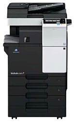
Konica-Minolta bizhub C227
Рейтинг

 Актуальный
Тип устройства
МФУ
Технология печати
лазерная
Макс. формат
A3
Число страниц в месяц
80000
Цветность печати
цветная
Общие характеристики |
|
|---|---|
Макс. формат |
A3 |
Технология печати |
лазерная |
Тип |
лазерный/светодиодный |
Размещение |
напольный |
Область применения |
средний офис |
Число страниц в месяц |
80 000 |
Цветность печати |
цветная |
Тип устройства |
МФУ |
Копир |
|
Сканер |
|
Факс |
|
Телефон |
|
Печать фотографий |
|
Принтер |
|
Макс, длина отпечатка |
420 |
Количество цветов |
4 |
Макс, ширина отпечатка |
297 |
Время разогрева |
20 |
Двусторонняя печать |
|
Прямая печать |
|
Печать без полей |
|
Система непрерывной подачи чернил |
|
Пигментные чернила |
|
Макс, разрешение для ч/б печати |
|
| По Y | 600 |
| По Y | 1 200 |
| По X | 1 800 |
Скорость цветной печати |
|
| A4 | 22 |
Копир |
|
Шаг масштабирования |
0,1 |
Время выхода первой копии |
6,8 |
Макс, количество копий за цикл |
9 999 |
Значение масштаба |
|
| Максимальное | 4 |
| Минимальное | 0,25 |
Макс, разрешение (ч/б) |
|
| По X | 600 |
| По Y | 600 |
Скорость ч/б копирования |
|
| A3 | 14 |
Сканер |
|
Макс. формат оригинала |
A3 |
Тип сканера |
планшетный/протяжный |
Устройство автоподачи оригиналов |
двустороннее |
Стандарт WIA |
|
Слайд-адаптер |
|
Емкость устройства автоподачи оригиналов |
100 |
Отправка изображения по e-mail |
|
Стандарт TWAIN |
|
Макс, размер сканирования |
|
| По X | 297 |
Разрешение сканера |
|
| По Х | 600 |
Скорость сканирования |
|
| Ч/б | 45 |
| Цветн, | 45 |
Расходные материалы |
|
Количество картриджей |
4 |
Ресурс ч/б картриджа/тонера |
24 000 |
Ресурс цветного картриджа/тонера |
21 000 |
Ресурс девелопера |
600 000 |
Печать на: |
|
| Рулоне |
|
| CD/DVD |
|
| Фотобумаге |
|
| Конвертах |
|
| Матовой бумаге |
|
| Глянцевой бумаге |
|
| Этикетках |
|
| Пленках |
|
| Карточках |
|
Плотность бумаги |
|
| Максимальная | 256 |
| Минимальная | 60 |
Факс |
|
PC Fax |
|
Цветной |
|
Телефон |
|
Беспроводная трубка |
|
АОН |
|
Стандарт DECT |
|
Caller ID |
|
Автоответчик |
|
Спикерфон |
|
Проводная трубка |
|
Шрифты и языки управления |
|
Языки управления |
|
| PPDS |
|
| PostScript 2 |
|
| PCL 5c |
|
|
|
|
| PostScript 3 |
|
| PostScript |
|
| PCL 6 |
|
| PCL 5e |
|
Количество установленных шрифтов |
|
| PCL | 80 |
| PostScript | 137 |
Лотки |
|
Емкость лотка ручной подачи |
100 |
Подача бумаги |
|
| Стандартная | 1 100 |
| Максимальная | 3 600 |
Вывод бумаги |
|
| Стандартный | 250 |
| Максимальный | 3 200 |
Финишер |
|
Степлер |
|
Сортировка со сдвигом |
|
Сортер |
|
Электронная сортировка |
|
Брошюровщик |
|
Интерфейсы |
|
Версия USB |
2,0 |
Инфракрасный порт |
|
FireWire (IEEE 1394) |
|
Wi-Fi |
|
Wi-Fi 802.11n |
|
Bluetooth |
|
LPT |
|
Устройство для чтения карт памяти |
|
RS-232 |
|
AirPrint |
|
USB |
|
Веб-интерфейс |
|
Ethernet (RJ-45) |
|
Память/Процессор |
|
Емкость жесткого диска |
250 |
Частота процессора |
1 200 |
Макс, объем памяти |
4 096 |
Объем памяти |
2 048 |
Процессор |
PowerPC MPC8536 |
Дополнительная информация |
|
Диагональ дисплея |
7 |
Экран |
|
Работа от аккумулятора |
|
Поддержка ОС |
|
| DOS |
|
| Windows |
|
| Linux |
|
| Mac OS |
|
Потребляемая мощность |
|
| При работе | 1 580 |
Габариты |
|
Ширина |
585 |
Глубина |
660 |
Вес |
72 |
Высота |
735 |
Модули
REVERSAL SECTION
BYPASS TRAY SECTION
CONVEYANCE SECTION 2
OPERATION PANEL SECTION
EXTERNAL PARTS 2
ELECTRICAL COMPONENTS
DRIVE SECTION
2ND CASSETTE SECTION
ELECTRICAL COMPONENTS 2
PAPER EXIT SECTION 2
REVERSAL SECTION 2
SCANNER SECTION
IMAGE TRANSFER BELT SECTION
ERASE LAMP SECTION
WASTE TONER BOX SECTION
PH UNIT/HIGH VOLTAGE SECTION
CASSETTE RAIL SECTION
VERTICAL CONVEYANCE SECTION 2
INNER COVER SECTION
PAPER EXIT SECTION
PAPER SIZE DETECTION SECTION
1ST CASSETTE SECTION 2
Vertical conveyance Section
DRIVE SECTION 2
MAIN POWER SUPPLY SECTION
PAPER FEED SECTION
TONER SUPPLY SECTION
2ND CASSETTE SECTION 2
VERTICAL CONVEYANCE DOOR SECTION
1ST CASSETTE SECTION
TONER SUPPLY SECTION 2
2ND PAPER FEED SECTION 2
CONVEYANCE SECTION
2ND PAPER FEED SECTION
EXTERNAL PARTS
FUSING SECTION
OZONE DUCT SECTION
BYPASS TRAY SECTION 2
TONER SUPPLY SECTION 3
SCANNER SECTION 2
1ST PAPER FEED SECTION 2
DV LOCK LEVER SECTION
1ST PAPER FEED SECTION
SCANNER SECTION 3
Детали REVERSAL SECTION 2

| Деталь: | Guide Door /Right |
| Парткод: | A797810101 |
| Деталь: | Label Paper supply |
| Парткод: | A7AH943000 |
| Деталь: | GUIDE |
| Парткод: | A797811901 |
| Деталь: | Support Part |
| Парткод: | A797811801 |
| Деталь: | Reinforce Plate /Rear |
| Парткод: | A797810200 |
| Деталь: | Reinforce Plate /Front |
| Парткод: | A797810300 |
| Деталь: | Guide Door /Lower |
| Парткод: | A797811700 |
| Деталь: | Roller /B |
| Парткод: | A797813900 |
| Деталь: | BUSHING |
| Парткод: | A02E815200 |
| Деталь: | Pressing Spring /A |
| Парткод: | A797814400 |
| Деталь: | Guide Plate /4 |
| Парткод: | A797813100 |
| Деталь: | Stepping motor |
| Парткод: | A7PUM10400 |
| Деталь: | Panel /Rear |
| Парткод: | A797815000 |
| Деталь: | Cover /B |
| Парткод: | A797814201 |
| Деталь: | Gear18T |
| Парткод: | A797717200 |
| Деталь: | GEAR 24T |
| Парткод: | A797717100 |
| Деталь: | Collar /A |
| Парткод: | A161813801 |
| Деталь: | MOUNTING PLATE |
| Парткод: | A797717000 |
| Деталь: | Drive Belt /B |
| Парткод: | A797717300 |
| Деталь: | Pulley 22/24T |
| Парткод: | A797815200 |
| Деталь: | Timing belt 126L |
| Парткод: | A797815300 |
| Деталь: | Pulley 20/35T |
| Парткод: | A797815100 |
| Деталь: | ADU Drive harness |
| Парткод: | A797N10M01 |
| Деталь: | Multiple Bypass Tray Assy |
| Парткод: | A797R72500 |
| Деталь: | MOUNTING PLATE |
| Парткод: | A797603000 |
| Деталь: | Guide Sheet |
| Парткод: | A161594700 |
| Деталь: | HOLDER |
| Парткод: | A7AH600300 |
| Деталь: | Paper feed Shaft |
| Парткод: | A7AH601100 |
| Деталь: | Slide Stopper |
| Парткод: | A161594400 |
| Деталь: | ROLLER |
| Парткод: | A00F623201 |
| Деталь: | BUSHING |
| Парткод: | A02E596300 |
| Деталь: | SHAFT |
| Парткод: | A7AH602701 |
| Деталь: | Paper feed Cam |
| Парткод: | A161593300 |
| Деталь: | Drive Frame |
| Парткод: | A797600500 |
| Деталь: | Bypass Cover |
| Парткод: | A797605100 |
| Деталь: | BUSHING |
| Парткод: | 1134304301 |
| Деталь: | GEAR 20T |
| Парткод: | A7AH603000 |
| Деталь: | Bypass Gear |
| Парткод: | A7AH602200 |
| Деталь: | REINFORCE PLATE |
| Парткод: | A797604100 |
| Деталь: | COVER |
| Парткод: | A7AH604300 |
| Деталь: | CONVEYANCE SOLENOID |
| Парткод: | A034M20100 |
| Деталь: | CLUTCH |
| Парткод: | A7AHM20400 |
| Деталь: | Drive Cover |
| Парткод: | A797600800 |
| Деталь: | SEAL |
| Парткод: | A7AH604900 |
| Деталь: | LEVER |
| Парткод: | A7AH603100 |
| Деталь: | COMPRESSING COIL SPRING |
| Парткод: | A7AH603200 |
| Деталь: | CLUTCH ASSY |
| Парткод: | A7AHR72700 |
| Деталь: | GEAR 24T |
| Парткод: | A7AH604700 |
| Деталь: | ROLL |
| Парткод: | A797701000 |
| Деталь: | BUSHING |
| Парткод: | A797702700 |
| Деталь: | SHAFT |
| Парткод: | A797700500 |
| Деталь: | Guide Sheet /B |
| Парткод: | A5C1701400 |
| Деталь: | Ground Spring /D |
| Парткод: | A797700801 |
| Деталь: | Gear14T |
| Парткод: | A797700700 |
| Деталь: | BUSHING |
| Парткод: | A02E596300 |
| Деталь: | FIXED POWER RESISTORS |
| Парткод: | V800500300 |
| Деталь: | TORSION COIL SPRING |
| Парткод: | A797701600 |
| Деталь: | Pressing Spring /B |
| Парткод: | A797702500 |
| Деталь: | MOUNTING PLATE |
| Парткод: | A797703000 |
| Деталь: | Pressing Spring /A |
| Парткод: | A797702000 |
| Деталь: | Pressing Spring /C |
| Парткод: | A797702600 |
| Деталь: | BUSHING |
| Парткод: | A161210200 |
| Деталь: | Guide Plate /Inside |
| Парткод: | A797700102 |
| Деталь: | Guide Sheet /A |
| Парткод: | A161701301 |
| Деталь: | GROUND PLATE |
| Парткод: | A7AH134600 |
| Деталь: | MOUNTING PLATE |
| Парткод: | A797162801 |
| Деталь: | FERRITECORE |
| Парткод: | A3EWM90300 |
| Деталь: | INTERFACE CABLE |
| Парткод: | A797N15600 |
| Деталь: | HOLDER |
| Парткод: | A7AH162100 |
| Деталь: | PANEL ASSEMBLY |
| Парткод: | A797M70200 |
| Деталь: | SEAL |
| Парткод: | A7AH162001 |
| Деталь: | COVER |
| Парткод: | A797166700 |
| Деталь: | LENS |
| Парткод: | A7AH161801 |
| Деталь: | Cover /Right |
| Парткод: | A797161500 |
| Деталь: | COVER |
| Парткод: | A797166601 |
| Деталь: | MOUNTING PLATE |
| Парткод: | A797134501 |
| Деталь: | Cover /Left |
| Парткод: | A797161600 |
| Деталь: | Magnet /X |
| Парткод: | A0G6411200 |
| Деталь: | Cover /Front |
| Парткод: | A797161701 |
| Деталь: | COVER |
| Парткод: | A797161400 |
| Деталь: | INTERFACE CABLE |
| Парткод: | A7PUN15300 |
| Деталь: | COVER |
| Парткод: | A797161300 |
| Деталь: | COVER |
| Парткод: | A797161200 |
| Деталь: | COVER |
| Парткод: | A797163000 |
| Деталь: | COVER |
| Парткод: | A797161100 |
| Деталь: | MOUNTING PLATE |
| Парткод: | A797138500 |
| Деталь: | Cover /Right |
| Парткод: | A797161900 |
| Деталь: | Cover /Right rear |
| Парткод: | A797160500 |
| Деталь: | PULLING COIL SPRING |
| Парткод: | A161163900 |
| Деталь: | Cover /Right rear |
| Парткод: | A797160901 |
| Деталь: | Cover /Rear |
| Парткод: | A797166102 |
| Деталь: | COVER |
| Парткод: | A00J169100 |
| Деталь: | COVER |
| Парткод: | A797166400 |
| Деталь: | COVER |
| Парткод: | A797163300 |
| Деталь: | Cover /Rear |
| Парткод: | A797164700 |
| Деталь: | Cover /Rear |
| Парткод: | A797166200 |
| Деталь: | LABEL |
| Парткод: | A2X0945701 |
| Деталь: | LABEL CAUTION |
| Парткод: | A7PU941701 |
| Деталь: | GROUND PLATE |
| Парткод: | A797102600 |
| Деталь: | GUIDE |
| Парткод: | A797137800 |
| Деталь: | PHOTOINTERRUPTER |
| Парткод: | A5C1M50100 |
| Деталь: | GUIDE |
| Парткод: | A797137400 |
| Деталь: | MOUNTING PLATE |
| Парткод: | A797135200 |
| Деталь: | Connecting Detection harness |
| Парткод: | A797N11300 |
| Деталь: | MOUNTING PLATE |
| Парткод: | A797137500 |
| Деталь: | SEAL |
| Парткод: | A797137900 |
| Деталь: | PWB Assembly(PWB-MFP ASSY) |
| Парткод: | A797H02103 |
| Деталь: | MOUNTING PLATE |
| Парткод: | A797137101 |
| Деталь: | MOUNTING PLATE |
| Парткод: | A797137000 |
| Деталь: | SHOULDER SCREW |
| Парткод: | A161137600 |
| Деталь: | PWB Assmbly(PWB-SATA) |
| Парткод: | A7AHH02S02 |
| Деталь: | COVER |
| Парткод: | A797137201 |
| Деталь: | Support Rubber |
| Парткод: | A4EU138000 |
| Деталь: | SHOULDER SCREW |
| Парткод: | A5C1134200 |
| Деталь: | MOUNTING PLATE |
| Парткод: | A797139000 |
| Деталь: | SPACER |
| Парткод: | A5C1134111 |
| Деталь: | HDD |
| Парткод: | A2X0M72C00 |
| Деталь: | Signal Cable |
| Парткод: | A7AHN15100 |
| Деталь: | Power source Cable |
| Парткод: | A161N15J00 |
| Деталь: | MOUNTING PLATE |
| Парткод: | A797135000 |
| Деталь: | Power source Wiring |
| Парткод: | A797N10B00 |
| Деталь: | FAN MOTOR |
| Парткод: | 4556M10000 |
| Деталь: | SEAL |
| Парткод: | A797138800 |
| Деталь: | FERRITECORE |
| Парткод: | A3EWM90300 |
| Деталь: | EEPROM (2 pieces) |
| Парткод: | V864800107 |
| Деталь: | Harness /Control |
| Парткод: | A7AHN15A00 |
| Деталь: | SCREW |
| Парткод: | A7AH131300 |
| Деталь: | Gasket /2 |
| Парткод: | A797M90100 |
| Деталь: | GASKET |
| Парткод: | A7PUM92600 |
| Деталь: | Gasket /3 |
| Парткод: | A797M90200 |
| Деталь: | Toner Drive harness /3 |
| Парткод: | A797N11400 |
| Деталь: | Stepping motor |
| Парткод: | A7PUM10700 |
| Деталь: | HOLDER |
| Парткод: | A797240100 |
| Деталь: | Gear100T |
| Парткод: | A797240300 |
| Деталь: | COUPLING |
| Парткод: | A797241001 |
| Деталь: | Gear15T |
| Парткод: | A797240900 |
| Деталь: | Gear 50T |
| Парткод: | A797240500 |
| Деталь: | Gear 74T |
| Парткод: | A797240600 |
| Деталь: | Gear 30/67T |
| Парткод: | A797240400 |
| Деталь: | JOINT |
| Парткод: | A161240700 |
| Деталь: | PRESSURE SPRING |
| Парткод: | 4038541202 |
| Деталь: | TB Drive Assy |
| Парткод: | A797R71300 |
| Деталь: | GEAR 20T |
| Парткод: | A797240800 |
| Деталь: | PAPER FEED DRIVE ASSY |
| Парткод: | A797R71500 |
| Деталь: | Gear 66T |
| Парткод: | A797253500 |
| Деталь: | Gear 21/41T |
| Парткод: | A797259800 |
| Деталь: | Holding |
| Парткод: | A797221000 |
| Деталь: | GEAR 32T |
| Парткод: | A797253100 |
| Деталь: | Gear 24/29T |
| Парткод: | A797220700 |
| Деталь: | GEAR 44T |
| Парткод: | A797253200 |
| Деталь: | Gear 23/29T |
| Парткод: | A797220100 |
| Деталь: | Gear 31T |
| Парткод: | A797253600 |
| Деталь: | HOLD PLATE |
| Парткод: | A797221100 |
| Деталь: | Gear18T |
| Парткод: | A797254000 |
| Деталь: | MAIN DRIVE ASSY |
| Парткод: | A797R71100 |
| Деталь: | Brushless motor /30 |
| Парткод: | A7PUM10100 |
| Деталь: | 2nd Cassette Assy |
| Парткод: | A797R72100 |
| Деталь: | ROLL |
| Парткод: | A7AH629901 |
| Деталь: | Slide Part |
| Парткод: | A7AH622901 |
| Деталь: | RAIL |
| Парткод: | A7AH623400 |
| Деталь: | LEVER |
| Парткод: | A7AH624200 |
| Деталь: | PULLING COIL SPRING |
| Парткод: | A161626800 |
| Деталь: | LEVER |
| Парткод: | A161626602 |
| Деталь: | Label 2 |
| Парткод: | A7AH941200 |
| Деталь: | HANDLE |
| Парткод: | A7AH626901 |
| Деталь: | Cover /Lower |
| Парткод: | A797625200 |
| Деталь: | HOLDER |
| Парткод: | A7AH624300 |
| Деталь: | Label Paper supply |
| Парткод: | A7AH941001 |
| Деталь: | Paper feed Cassette |
| Парткод: | A797630100 |
| Деталь: | ROLL |
| Парткод: | A161623400 |
| Деталь: | Rail /Left |
| Парткод: | A7AH623201 |
| Деталь: | Wiring Cover |
| Парткод: | A797132900 |
| Деталь: | COVER |
| Парткод: | A797132500 |
| Деталь: | MOUNTING PLATE |
| Парткод: | A797132700 |
| Деталь: | MOUNTING PLATE |
| Парткод: | A797132100 |
| Деталь: | GUIDE PLATE |
| Парткод: | A797132200 |
| Деталь: | MOUNTING PLATE |
| Парткод: | A797132600 |
| Деталь: | MOUNTING PLATE |
| Парткод: | A797132400 |
| Деталь: | MOUNTING PLATE |
| Парткод: | A797132000 |
| Деталь: | SEESAW-SWITCH |
| Парткод: | 4038M60000 |
| Деталь: | AC Wiring /230V |
| Парткод: | A797N10200 |
| Деталь: | Power Supply Wiring |
| Парткод: | A02EN12513 |
| Деталь: | Guide /Upper |
| Парткод: | A797890100 |
| Деталь: | Neutralizing Brush |
| Парткод: | A797891400 |
| Деталь: | Guide Lever |
| Парткод: | A797890500 |
| Деталь: | GROUND SPRING |
| Парткод: | A797891100 |
| Деталь: | ROLL |
| Парткод: | A0P0901100 |
| Деталь: | TORSION COIL SPRING |
| Парткод: | A797890600 |
| Деталь: | SPRING |
| Парткод: | A797892700 |
| Деталь: | Cushion /A |
| Парткод: | A797892601 |
| Деталь: | SHAFT |
| Парткод: | A797891200 |
| Деталь: | GUIDE |
| Парткод: | A797891000 |
| Деталь: | Cushion /B |
| Парткод: | A797892300 |
| Деталь: | PHOTOINTERRUPTER |
| Парткод: | A5C1M50100 |
| Деталь: | ROLL |
| Парткод: | A5C1891100 |
| Деталь: | COLLAR |
| Парткод: | A0ED897700 |
| Деталь: | Conveyance Detection harness /L ower |
| Парткод: | A797N11100 |
| Деталь: | SEAL |
| Парткод: | A797891900 |
| Деталь: | SHAFT |
| Парткод: | 4025598401 |
| Деталь: | BUSHING |
| Парткод: | A0ED891100 |
| Деталь: | SEAL |
| Парткод: | A797891800 |
| Деталь: | Guide /Lower |
| Парткод: | A797890001 |
| Деталь: | SEAL |
| Парткод: | A797892000 |
| Деталь: | SEAL |
| Парткод: | A797892100 |
| Деталь: | Mounting Plate /Rear |
| Парткод: | A797890201 |
| Деталь: | Pulley 36T |
| Парткод: | A797891300 |
| Деталь: | SHAFT STOPPER 4 |
| Парткод: | 56AA40490 |
| Деталь: | GROUND SPRING |
| Парткод: | A797892400 |
| Деталь: | Ground Contact /Lower |
| Парткод: | A797892500 |
| Деталь: | ROLLER |
| Парткод: | A797890300 |
| Деталь: | ROLL |
| Парткод: | 4004590301 |
| Деталь: | Cushion /C |
| Парткод: | A797892900 |
| Деталь: | Torsion Coil spring /Front |
| Парткод: | A797815700 |
| Деталь: | Idler Roller /A |
| Парткод: | A161825700 |
| Деталь: | Torsion Coil spring /Rear |
| Парткод: | A797815800 |
| Деталь: | GUIDE PLATE |
| Парткод: | A797812600 |
| Деталь: | GUIDE PLATE |
| Парткод: | A797812500 |
| Деталь: | GUIDE |
| Парткод: | A797815600 |
| Деталь: | Guide Plate /1 |
| Парткод: | A797812101 |
| Деталь: | BUSHING |
| Парткод: | 4030581101 |
| Деталь: | Gear18T |
| Парткод: | A161819200 |
| Деталь: | SPACER |
| Парткод: | A797814600 |
| Деталь: | Guide Plate /2 |
| Парткод: | A797812201 |
| Деталь: | RING |
| Парткод: | A797813000 |
| Деталь: | TORSION COIL SPRING |
| Парткод: | A797812800 |
| Деталь: | BUSHING |
| Парткод: | A797815500 |
| Деталь: | Roller /1 |
| Парткод: | A797812401 |
| Деталь: | ACTUATOR |
| Парткод: | A797812700 |
| Деталь: | Label M2 |
| Парткод: | A797946500 |
| Деталь: | Guide Plate /3 |
| Парткод: | A797812300 |
| Деталь: | Read Cover /Rear |
| Парткод: | A797266200 |
| Деталь: | Read Cover /Rear |
| Парткод: | A7AH267000 |
| Деталь: | SHOULDER SCREW |
| Парткод: | A7AH267201 |
| Деталь: | SEAL |
| Парткод: | A7AH266800 |
| Деталь: | IR Cover /Upper Assy |
| Парткод: | A797R72300 |
| Деталь: | LABEL |
| Парткод: | A0HF952400 |
| Деталь: | Read Cover /Front |
| Парткод: | A7AH266505 |
| Деталь: | Read Cover /Left |
| Парткод: | A797266601 |
| Деталь: | COVER |
| Парткод: | A02E167700 |
| Деталь: | Image Transfer Belt Kit |
| Парткод: | A797R70011 |
| Деталь: | SEAL |
| Парткод: | A797102701 |
| Деталь: | Arm /Front |
| Парткод: | A5C1112800 |
| Деталь: | Lever /Front |
| Парткод: | A161112500 |
| Деталь: | SCREW |
| Парткод: | 4163529301 |
| Деталь: | COMPRESSING COIL SPRING |
| Парткод: | A0ED111000 |
| Деталь: | RAIL |
| Парткод: | A797110200 |
| Деталь: | RAIL |
| Парткод: | A161110300 |
| Деталь: | RAIL |
| Парткод: | A797110101 |
| Деталь: | Contact /Color |
| Парткод: | A0ED111500 |
| Деталь: | CONTACT |
| Парткод: | A797111700 |
| Деталь: | Transfer Wiring /2 |
| Парткод: | A797N10W00 |
| Деталь: | Transfer Wiring /1 |
| Парткод: | A797N10V00 |
| Деталь: | CONTACT |
| Парткод: | A0ED112000 |
| Деталь: | DETECTING PLATE |
| Парткод: | A161110500 |
| Деталь: | PULLING COIL SPRING |
| Парткод: | A0ED110900 |
| Деталь: | CONTACT |
| Парткод: | A797112300 |
| Деталь: | Lever /Rear |
| Парткод: | A797112100 |
| Деталь: | Arm /Rear |
| Парткод: | A797112900 |
| Деталь: | Erase/ YMC Assy |
| Парткод: | A797R70400 |
| Деталь: | Erase/ K Assy |
| Парткод: | A797R70500 |
| Деталь: | Relay Wiring /2 |
| Парткод: | A797N11500 |
| Деталь: | HOLDER |
| Парткод: | A797134701 |
| Деталь: | GUIDE |
| Парткод: | A161138500 |
| Деталь: | RAIL |
| Парткод: | A797105600 |
| Деталь: | SEAL |
| Парткод: | A797105700 |
| Деталь: | WASTE TONER DRIVE ASSY |
| Парткод: | A797R71400 |
| Деталь: | HOLD PLATE |
| Парткод: | A797245500 |
| Деталь: | Gear 20/20T |
| Парткод: | A0ED245000 |
| Деталь: | Gear 16/40T |
| Парткод: | A161245100 |
| Деталь: | Gear 16/51T |
| Парткод: | A161245400 |
| Деталь: | Fixing Claw |
| Парткод: | A161165700 |
| Деталь: | HOLDER |
| Парткод: | A797258601 |
| Деталь: | SHAFT |
| Парткод: | A797245300 |
| Деталь: | Waste Toner Pipe Assy |
| Парткод: | A797R71600 |
| Деталь: | MOUNTING PLATE |
| Парткод: | A797151201 |
| Деталь: | DUCT |
| Парткод: | A797151102 |
| Деталь: | FAN MOTOR |
| Парткод: | 4139M10000 |
| Деталь: | SCREW |
| Парткод: | 4163529301 |
| Деталь: | Protection Cover |
| Парткод: | A797134000 |
| Деталь: | FlatCable |
| Парткод: | A797N12001 |
| Деталь: | POSITIONING PLATE |
| Парткод: | A161105400 |
| Деталь: | PRINT HEAD ASSY |
| Парткод: | A8WVR70000 |
| Деталь: | MOUNTING PLATE |
| Парткод: | A797102200 |
| Деталь: | HOLDER |
| Парткод: | A797138100 |
| Деталь: | FlatCable |
| Парткод: | A797N12100 |
| Деталь: | CONNECTOR |
| Парткод: | V651010002 |
| Деталь: | Cover Post |
| Парткод: | A797151400 |
| Деталь: | HIGH VOLTAGE UNIT |
| Парткод: | A797M40601 |
| Деталь: | STOPPER SHAFT |
| Парткод: | A797151500 |
| Деталь: | MOUNTING PLATE |
| Парткод: | A797101600 |
| Деталь: | SHAFT |
| Парткод: | A797101900 |
| Деталь: | LEVER |
| Парткод: | A797101700 |
| Деталь: | COVER |
| Парткод: | A797101800 |
| Деталь: | RUBBER FOOT |
| Парткод: | 0996305501 |
| Деталь: | RAIL |
| Парткод: | A797102901 |
| Деталь: | RAIL |
| Парткод: | A797103001 |
| Деталь: | STOPPER |
| Парткод: | A7AH120102 |
| Деталь: | STOPPER |
| Парткод: | A7AH121301 |
| Деталь: | GEAR 20T |
| Парткод: | A797709100 |
| Деталь: | Drive Belt /A |
| Парткод: | A797719000 |
| Деталь: | COLLAR |
| Парткод: | A0ED811900 |
| Деталь: | Pressing Spring |
| Парткод: | A797711200 |
| Деталь: | Idler Roller /A |
| Парткод: | A161825700 |
| Деталь: | Bushing /1 |
| Парткод: | A161713100 |
| Деталь: | Roller /A |
| Парткод: | A797710500 |
| Деталь: | BUSHING |
| Парткод: | A02E815200 |
| Деталь: | Label M3 |
| Парткод: | A797946400 |
| Деталь: | Guide Plate /A |
| Парткод: | A797710201 |
| Деталь: | Ground Plate /D |
| Парткод: | A797712000 |
| Деталь: | Guide Plate /B |
| Парткод: | A797710300 |
| Деталь: | SCREW |
| Парткод: | 4163529301 |
| Деталь: | Mounting Plate /Front |
| Парткод: | A797715400 |
| Деталь: | PLATE SPRING |
| Парткод: | A797716200 |
| Деталь: | HOLD PLATE |
| Парткод: | A797715300 |
| Деталь: | MOUNTING PLATE |
| Парткод: | A797715800 |
| Деталь: | Conveyance Wiring /2 |
| Парткод: | A797N10K00 |
| Деталь: | COLLAR |
| Парткод: | A797716100 |
| Деталь: | Ground Spring /D |
| Парткод: | A797712900 |
| Деталь: | COVER |
| Парткод: | A797715700 |
| Деталь: | Conveyance Spring /B |
| Парткод: | A161714600 |
| Деталь: | TORSION SPRING |
| Парткод: | A02E813100 |
| Деталь: | PHOTOINTERRUPTER |
| Парткод: | A5C1M50100 |
| Деталь: | ACTUATOR |
| Парткод: | A797716000 |
| Деталь: | Pulley 22T |
| Парткод: | A797716300 |
| Деталь: | DUCT |
| Парткод: | A797151000 |
| Деталь: | SPEAKER |
| Парткод: | A0P0M73100 |
| Деталь: | MICRO SWITCH |
| Парткод: | 9J06M60100 |
| Деталь: | TORSION COIL SPRING |
| Парткод: | A161151200 |
| Деталь: | SHOULDER SCREW |
| Парткод: | A161137100 |
| Деталь: | COVER |
| Парткод: | A797134800 |
| Деталь: | HOLDER |
| Парткод: | A797132302 |
| Деталь: | Cover /Front |
| Парткод: | A797165102 |
| Деталь: | PROTECTION PART |
| Парткод: | A161165300 |
| Деталь: | Label/ K |
| Парткод: | A797942500 |
| Деталь: | LABEL |
| Парткод: | A797942600 |
| Деталь: | LABEL |
| Парткод: | A797942100 |
| Деталь: | 2nd Front Cover/ Lower Assy |
| Парткод: | A797R71000 |
| Деталь: | LABEL |
| Парткод: | A161943000 |
| Деталь: | TORSION COIL SPRING |
| Парткод: | A161151300 |
| Деталь: | PHOTOINTERRUPTER |
| Парткод: | A0VDM50200 |
| Деталь: | PHOTOINTERRUPTER |
| Парткод: | A5C1M50100 |
| Деталь: | MOUNTING PLATE |
| Парткод: | A797134600 |
| Деталь: | Relay Wiring /1 |
| Парткод: | A797N10N00 |
| Деталь: | Drive Wiring |
| Парткод: | A797N10D00 |
| Деталь: | PM Stepping motor |
| Парткод: | A797M10300 |
| Деталь: | Timing belt 226L |
| Парткод: | A797891500 |
| Деталь: | COVER |
| Парткод: | A797892200 |
| Деталь: | SHOULDER SCREW |
| Парткод: | 1164202801 |
| Деталь: | MOTOR |
| Парткод: | 9J06M10300 |
| Деталь: | SWITCH |
| Парткод: | A797M60100 |
| Деталь: | Main body Wiring /1 |
| Парткод: | A797N10A01 |
| Деталь: | Lifting Shaft |
| Парткод: | A7AH621601 |
| Деталь: | Lever /2 |
| Парткод: | A797623600 |
| Деталь: | GROUND SPRING |
| Парткод: | A7AH622100 |
| Деталь: | Regulating Plate /Rear |
| Парткод: | A797620900 |
| Деталь: | CUSHION |
| Парткод: | A161624100 |
| Деталь: | Operation Lever |
| Парткод: | A7AH621300 |
| Деталь: | PULLING COIL SPRING |
| Парткод: | A7AH621000 |
| Деталь: | LOCK LEVER |
| Парткод: | A7AH621200 |
| Деталь: | LABEL |
| Парткод: | A161943000 |
| Деталь: | REGULATING PLATE |
| Парткод: | A7AH620801 |
| Деталь: | SHOULDER SCREW |
| Парткод: | A7AH628200 |
| Деталь: | GEAR |
| Парткод: | A161620701 |
| Деталь: | Regulating Plate /Rear |
| Парткод: | A7AH622401 |
| Деталь: | GUIDE |
| Парткод: | A7AH629600 |
| Деталь: | LEVER |
| Парткод: | 4030320601 |
| Деталь: | Label Position |
| Парткод: | A7AH941300 |
| Деталь: | REGULATING PLATE |
| Парткод: | A7AH621701 |
| Деталь: | LEVER |
| Парткод: | A797623500 |
| Деталь: | Adjusting Plate |
| Парткод: | A797620600 |
| Деталь: | SCREW |
| Парткод: | 4163529301 |
| Деталь: | LEVER |
| Парткод: | A7AH621401 |
| Деталь: | PLATE SPRING |
| Парткод: | A7AH621801 |
| Деталь: | LIFTING PLATE |
| Парткод: | A7AH620400 |
| Деталь: | Separating Sheet |
| Парткод: | A7AH627000 |
| Деталь: | DETECTING PLATE |
| Парткод: | A7AH622201 |
| Деталь: | BUSHING |
| Парткод: | A7AH621501 |
| Деталь: | SHAFT STOPPER 4 |
| Парткод: | 56AA40490 |
| Деталь: | Pulling Coil spring /3 |
| Парткод: | A797623700 |
| Деталь: | 2ND TRANSFER ROLLER ASSY |
| Парткод: | A797R71800 |
| Деталь: | Transfer Holder /2 |
| Парткод: | A161551500 |
| Деталь: | Compressing Coil spring /2 |
| Парткод: | A0ED551000 |
| Деталь: | SHOULDER SCREW |
| Парткод: | 4011585202 |
| Деталь: | Ground Spring /B |
| Парткод: | A5C1711000 |
| Деталь: | Ground Contact /C |
| Парткод: | A797711100 |
| Деталь: | Spring /C |
| Парткод: | A161712700 |
| Деталь: | ACTUATOR |
| Парткод: | A0ED703800 |
| Деталь: | FIXED POWER RESISTORS |
| Парткод: | V800500300 |
| Деталь: | PHOTOINTERRUPTER |
| Парткод: | A5C1M50100 |
| Деталь: | Holder /A |
| Парткод: | A797710100 |
| Деталь: | Vertical Transport Assy |
| Парткод: | A797R72200 |
| Деталь: | Transfer Holder /2 |
| Парткод: | A161550700 |
| Деталь: | COMPRESSING COIL SPRING |
| Парткод: | A0ED551100 |
| Деталь: | Ground Plate /A |
| Парткод: | A797710900 |
| Деталь: | Ground Spring /A |
| Парткод: | A161712401 |
| Деталь: | NEUTRALIZING NEEDLE |
| Парткод: | 1164420204 |
| Деталь: | Ground Spring /C |
| Парткод: | A797712500 |
| Деталь: | Adjusting Plate |
| Парткод: | A797108300 |
| Деталь: | brushless Motor /20 |
| Парткод: | A7PUM10000 |
| Деталь: | BUSHING |
| Парткод: | A797232300 |
| Деталь: | MOUNTING PLATE |
| Парткод: | A797255600 |
| Деталь: | Slide Shaft Holder |
| Парткод: | A03U812800 |
| Деталь: | GEAR 34T |
| Парткод: | A797230600 |
| Деталь: | GEAR 28T |
| Парткод: | A797230800 |
| Деталь: | Gear 21/87T |
| Парткод: | A797228000 |
| Деталь: | SHAFT |
| Парткод: | A797231800 |
| Деталь: | Fusing Drive Assy |
| Парткод: | A797R71200 |
| Деталь: | CONTACT |
| Парткод: | A797814000 |
| Деталь: | MOUNTING PLATE |
| Парткод: | A797255700 |
| Деталь: | Gear18T |
| Парткод: | A797230700 |
| Деталь: | BUSHING |
| Парткод: | A161702200 |
| Деталь: | Gear16T |
| Парткод: | A797228700 |
| Деталь: | Fusing Rail /Rear |
| Парткод: | A797110500 |
| Деталь: | GEAR 16T |
| Парткод: | 4038258001 |
| Деталь: | BUSHING |
| Парткод: | A0ED259700 |
| Деталь: | MOUNTING PLATE |
| Парткод: | A161258800 |
| Деталь: | GEAR 26T |
| Парткод: | A0ED257500 |
| Деталь: | SHAFT |
| Парткод: | A161259400 |
| Деталь: | TORSION COIL SPRING |
| Парткод: | A161232501 |
| Деталь: | SHAFT |
| Парткод: | A797258700 |
| Деталь: | CLUTCH |
| Парткод: | A7AHM20400 |
| Деталь: | Gear 20/72T |
| Парткод: | A797230500 |
| Деталь: | GEAR 37T |
| Парткод: | A797228100 |
| Деталь: | Gear 20/29T |
| Парткод: | A797259100 |
| Деталь: | SHAFT |
| Парткод: | A797228300 |
| Деталь: | FAN MOTOR |
| Парткод: | 4139M10000 |
| Деталь: | MOUNTING PLATE |
| Парткод: | A797166300 |
| Деталь: | Power supply Assy /220-240V |
| Парткод: | A797R70900 |
| Деталь: | SHOULDER SCREW |
| Парткод: | A7AH569400 |
| Деталь: | PULLING COIL SPRING |
| Парткод: | A7AH568900 |
| Деталь: | Open/close Lever |
| Парткод: | A797568800 |
| Деталь: | PAPER FEED ASSY |
| Парткод: | A797R71900 |
| Деталь: | COVER |
| Парткод: | A797579000 |
| Деталь: | PULLING COIL SPRING |
| Парткод: | A797568300 |
| Деталь: | Paper feed Guide/ 2nd |
| Парткод: | A797578401 |
| Деталь: | GUIDE |
| Парткод: | A797568500 |
| Деталь: | PULLING COIL SPRING |
| Парткод: | A797568900 |
| Деталь: | Paper feed Guide/ 1st |
| Парткод: | A797568400 |
| Деталь: | COVER |
| Парткод: | A797405200 |
| Деталь: | Label Toner 1 |
| Парткод: | A0ED940600 |
| Деталь: | Seal /1 |
| Парткод: | A161404001 |
| Деталь: | COVER |
| Парткод: | A797402501 |
| Деталь: | Sub Hopper Assy |
| Парткод: | A797R71700 |
| Деталь: | SPACER |
| Парткод: | A161403901 |
| Деталь: | SEAL |
| Парткод: | A797404000 |
| Деталь: | SHUTTER |
| Парткод: | A797402800 |
| Деталь: | SEAL |
| Парткод: | A161402502 |
| Деталь: | COVER |
| Парткод: | A797402700 |
| Деталь: | SEAL |
| Парткод: | A797403300 |
| Деталь: | Magnet /X |
| Парткод: | A0G6411200 |
| Деталь: | Lifting Shaft |
| Парткод: | A7AH621601 |
| Деталь: | Lever /2 |
| Парткод: | A797623600 |
| Деталь: | GROUND SPRING |
| Парткод: | A7AH622100 |
| Деталь: | Regulating Plate /Rear |
| Парткод: | A797620900 |
| Деталь: | CUSHION |
| Парткод: | A161624100 |
| Деталь: | Operation Lever |
| Парткод: | A7AH621300 |
| Деталь: | PULLING COIL SPRING |
| Парткод: | A7AH621000 |
| Деталь: | LOCK LEVER |
| Парткод: | A7AH621200 |
| Деталь: | LABEL |
| Парткод: | A161943000 |
| Деталь: | REGULATING PLATE |
| Парткод: | A7AH620801 |
| Деталь: | SHOULDER SCREW |
| Парткод: | A7AH628200 |
| Деталь: | GEAR |
| Парткод: | A161620701 |
| Деталь: | Regulating Plate /Rear |
| Парткод: | A7AH622401 |
| Деталь: | GUIDE |
| Парткод: | A7AH629600 |
| Деталь: | LEVER |
| Парткод: | 4030320601 |
| Деталь: | Label Position |
| Парткод: | A7AH941300 |
| Деталь: | REGULATING PLATE |
| Парткод: | A7AH621701 |
| Деталь: | LEVER |
| Парткод: | A797623500 |
| Деталь: | Adjusting Plate |
| Парткод: | A797620600 |
| Деталь: | SCREW |
| Парткод: | 4163529301 |
| Деталь: | LEVER |
| Парткод: | A7AH621401 |
| Деталь: | PLATE SPRING |
| Парткод: | A7AH621801 |
| Деталь: | LIFTING PLATE |
| Парткод: | A7AH620400 |
| Деталь: | Separating Sheet |
| Парткод: | A7AH627000 |
| Деталь: | DETECTING PLATE |
| Парткод: | A7AH622201 |
| Деталь: | BUSHING |
| Парткод: | A7AH621501 |
| Деталь: | SHAFT STOPPER 4 |
| Парткод: | 56AA40490 |
| Деталь: | Pulling Coil spring /3 |
| Парткод: | A797623700 |
| Деталь: | LOCK CLAW |
| Парткод: | A0ED712100 |
| Деталь: | Support Part /Upper |
| Парткод: | A797811500 |
| Деталь: | Lock plate |
| Парткод: | A797811000 |
| Деталь: | Open/close Handle |
| Парткод: | A797811100 |
| Деталь: | Lock /Middle |
| Парткод: | A797811400 |
| Деталь: | TORSION COIL SPRING |
| Парткод: | A797815900 |
| Деталь: | Lock Claw /Lower |
| Парткод: | A797811600 |
| Деталь: | Lock Part /Lower |
| Парткод: | A797811300 |
| Деталь: | Pulling Spring |
| Парткод: | A64J815500 |
| Деталь: | ROLL |
| Парткод: | A161815400 |
| Деталь: | SHAFT |
| Парткод: | A161815300 |
| Деталь: | Paper feed Guide |
| Парткод: | A797810401 |
| Деталь: | Paper feed Guide |
| Парткод: | A797600700 |
| Деталь: | HOLDER |
| Парткод: | A797108400 |
| Деталь: | Adjusting Plate |
| Парткод: | A797108200 |
| Деталь: | Adjusting Plate |
| Парткод: | A797108100 |
| Деталь: | 1st Cassette Assy |
| Парткод: | A797R72000 |
| Деталь: | ROLL |
| Парткод: | A7AH629901 |
| Деталь: | Slide Part |
| Парткод: | A7AH622901 |
| Деталь: | RAIL |
| Парткод: | A7AH623400 |
| Деталь: | LEVER |
| Парткод: | A7AH624100 |
| Деталь: | PULLING COIL SPRING |
| Парткод: | A161626800 |
| Деталь: | LEVER |
| Парткод: | A161626602 |
| Деталь: | Label 1 |
| Парткод: | A7AH941100 |
| Деталь: | HANDLE |
| Парткод: | A7AH626901 |
| Деталь: | Cover /Upper |
| Парткод: | A797625100 |
| Деталь: | HOLDER |
| Парткод: | A7AH624300 |
| Деталь: | Label Paper supply |
| Парткод: | A7AH941001 |
| Деталь: | Paper feed Cassette |
| Парткод: | A797620100 |
| Деталь: | ROLL |
| Парткод: | A161623400 |
| Деталь: | Rail /Left |
| Парткод: | A7AH623201 |
| Деталь: | Toner Drive harness /1 |
| Парткод: | A797N10X00 |
| Деталь: | GEAR 30T |
| Парткод: | A797402100 |
| Деталь: | COUPLING |
| Парткод: | A797402200 |
| Деталь: | GEAR 44T |
| Парткод: | A797401400 |
| Деталь: | Gear 31T |
| Парткод: | A797402000 |
| Деталь: | GEAR 24T |
| Парткод: | A797401500 |
| Деталь: | GEAR 37T |
| Парткод: | A797401600 |
| Деталь: | Gear19T |
| Парткод: | A797401800 |
| Деталь: | GEAR 36T |
| Парткод: | A797401100 |
| Деталь: | GEAR 24T |
| Парткод: | A797401200 |
| Деталь: | Gear18T |
| Парткод: | A797401000 |
| Деталь: | GEAR 22T |
| Парткод: | A797401700 |
| Деталь: | Gear 17/65T |
| Парткод: | A797401300 |
| Деталь: | BUSHING |
| Парткод: | 4163510201 |
| Деталь: | SPACER |
| Парткод: | A797402300 |
| Деталь: | SEAL |
| Парткод: | 4576536301 |
| Деталь: | HOLDER |
| Парткод: | A161403101 |
| Деталь: | SCREW |
| Парткод: | A161400100 |
| Деталь: | CASING |
| Парткод: | A797400000 |
| Деталь: | Stepping motor |
| Парткод: | A7PUM10700 |
| Деталь: | SEAL |
| Парткод: | 4333501201 |
| Деталь: | BUSHING |
| Парткод: | A161403000 |
| Деталь: | PHOTOINTERRUPTER |
| Парткод: | A5C1M50100 |
| Деталь: | HOLDER |
| Парткод: | A797400900 |
| Деталь: | Toner Detection harness |
| Парткод: | A797N10E00 |
| Деталь: | Toner Drive harness /2 |
| Парткод: | A797N10Y00 |
| Деталь: | MOUNTING PLATE |
| Парткод: | A797400700 |
| Деталь: | Release Lever |
| Парткод: | A7AH564101 |
| Деталь: | PULLING COIL SPRING |
| Парткод: | A797564400 |
| Деталь: | BUSHING |
| Парткод: | A02E815200 |
| Деталь: | FRAME |
| Парткод: | A797563900 |
| Деталь: | ACTUATOR |
| Парткод: | A7AH560800 |
| Деталь: | TORSION COIL SPRING |
| Парткод: | A797560701 |
| Деталь: | COMPRESSING COIL SPRING |
| Парткод: | A7AH561300 |
| Деталь: | PHOTOINTERRUPTER |
| Парткод: | A5C1M50100 |
| Деталь: | SHAFT STOPPER 4 |
| Парткод: | 56AA40490 |
| Деталь: | ROLLER |
| Парткод: | A00J563600 |
| Деталь: | TORQUE LIMITER |
| Парткод: | A0ED563900 |
| Деталь: | Support Shaft |
| Парткод: | A7AH565000 |
| Деталь: | HOLDER |
| Парткод: | A7AH563101 |
| Деталь: | GUIDE |
| Парткод: | A797569100 |
| Деталь: | COVER |
| Парткод: | A797701200 |
| Деталь: | ROLLER |
| Парткод: | A797700200 |
| Деталь: | GUIDE |
| Парткод: | 4038353701 |
| Деталь: | REINFORCE PLATE |
| Парткод: | A02E712902 |
| Деталь: | Guide Plate /Middle |
| Парткод: | A797700601 |
| Деталь: | Guide Sheet |
| Парткод: | A0ED700600 |
| Деталь: | PLATE SPRING |
| Парткод: | A7PU701100 |
| Деталь: | SHOULDER SCREW |
| Парткод: | A7PU701200 |
| Деталь: | BUSHING |
| Парткод: | A161702200 |
| Деталь: | GEAR 20T |
| Парткод: | A0ED700300 |
| Деталь: | Photo sensing |
| Парткод: | A797M50000 |
| Деталь: | Cushion /C |
| Парткод: | A161702100 |
| Деталь: | PHOTOINTERRUPTER |
| Парткод: | A5C1M50100 |
| Деталь: | Actuator /T |
| Парткод: | A797701700 |
| Деталь: | Spring /A |
| Парткод: | A161701100 |
| Деталь: | HUMIDITY SENSOR |
| Парткод: | A7AHM50400 |
| Деталь: | CLUTCH |
| Парткод: | A7AHM20400 |
| Деталь: | Conveyance Wiring /1 |
| Парткод: | A797N10H01 |
| Деталь: | MOUNTING PLATE |
| Парткод: | A797102400 |
| Деталь: | CLUTCH |
| Парткод: | A7AHM20400 |
| Деталь: | Gear 20/32T |
| Парткод: | A797563700 |
| Деталь: | CLUTCH |
| Парткод: | A7AHM20500 |
| Деталь: | BUSHING |
| Парткод: | A00J663200 |
| Деталь: | MOUNTING PLATE |
| Парткод: | A797579100 |
| Деталь: | DRIVE ROLLER |
| Парткод: | A797578100 |
| Деталь: | Conveyance Guide |
| Парткод: | A797578200 |
| Деталь: | ACTUATOR |
| Парткод: | A797578600 |
| Деталь: | TORSION COIL SPRING |
| Парткод: | A797578800 |
| Деталь: | Cushion /C |
| Парткод: | A161702100 |
| Деталь: | PHOTOINTERRUPTER |
| Парткод: | A5C1M50100 |
| Деталь: | MOUNTING PLATE |
| Парткод: | A797579300 |
| Деталь: | Paper feed Frame |
| Парткод: | A797565300 |
| Деталь: | Conveyance Guide |
| Парткод: | A7AH565702 |
| Деталь: | Paper feed Shaft |
| Парткод: | A797560600 |
| Деталь: | Paper feed Gear |
| Парткод: | A7AH562400 |
| Деталь: | CLUTCH |
| Парткод: | A02E561100 |
| Деталь: | ROLLER |
| Парткод: | A00J563600 |
| Деталь: | SHAFT STOPPER 4 |
| Парткод: | 56AA40490 |
| Деталь: | ROLLER |
| Парткод: | A5C1562200 |
| Деталь: | Conveyance Gear 28T |
| Парткод: | A7AH562600 |
| Деталь: | Idling Gear |
| Парткод: | A7AH562300 |
| Деталь: | Support Shaft |
| Парткод: | A7AH563400 |
| Деталь: | Protection Sheet |
| Парткод: | A7AH562900 |
| Деталь: | Conveyance Guide /4 |
| Парткод: | A7AH562100 |
| Деталь: | COMPRESSING COIL SPRING |
| Парткод: | A7AH562801 |
| Деталь: | Detecting Lever |
| Парткод: | A7AH561601 |
| Деталь: | Paperfeed Detection harness |
| Парткод: | A797N10Q01 |
| Деталь: | GUIDE |
| Парткод: | A797579600 |
| Деталь: | PAPER EXIT TRAY |
| Парткод: | A797161001 |
| Деталь: | Cover /Upper |
| Парткод: | A797160101 |
| Деталь: | Label Toner 2 |
| Парткод: | A0ED940700 |
| Деталь: | Paper exit Cover |
| Парткод: | A797164200 |
| Деталь: | COVER |
| Парткод: | A797162500 |
| Деталь: | Cover /Right front |
| Парткод: | A797160400 |
| Деталь: | SUCTION PLATE |
| Парткод: | 4038101401 |
| Деталь: | Cover /Front |
| Парткод: | A797160300 |
| Деталь: | Open/close Cover /Front |
| Парткод: | A797180100 |
| Деталь: | Plate /D |
| Парткод: | A0Y5944800 |
| Деталь: | Label ineo+ 227 |
| Парткод: | A798940200 |
| Деталь: | CLEANING PAD |
| Парткод: | A00J106202 |
| Деталь: | CLEANING MATERIAL |
| Парткод: | A5C1R71600 |
| Деталь: | BAND |
| Парткод: | A797162000 |
| Деталь: | Cover /Left front |
| Парткод: | A797160701 |
| Деталь: | Cover /Left |
| Парткод: | A797160600 |
| Деталь: | Cover /Left rear |
| Парткод: | A797161801 |
| Деталь: | Cover /Left rear |
| Парткод: | A797160801 |
| Деталь: | SEAL |
| Парткод: | A5C1404500 |
| Деталь: | Fusing Unit/ 220-240V |
| Парткод: | A797R70300 |
| Деталь: | MOUNTING PLATE |
| Парткод: | A161112200 |
| Деталь: | Adjusting Plate |
| Парткод: | A161112600 |
| Деталь: | Fusing Rail /Front |
| Парткод: | A797110400 |
| Деталь: | Heater Relay harness |
| Парткод: | A797N10400 |
| Деталь: | Duct /2 |
| Парткод: | A797150300 |
| Деталь: | SEALING PART |
| Парткод: | A797150500 |
| Деталь: | SEAL |
| Парткод: | A7PU143300 |
| Деталь: | Duct /3 |
| Парткод: | A797150400 |
| Деталь: | FILTER |
| Парткод: | A797152100 |
| Деталь: | COVER |
| Парткод: | A797150600 |
| Деталь: | FAN MOTOR |
| Парткод: | 9313100072 |
| Деталь: | SEAL |
| Парткод: | A02E117300 |
| Деталь: | Duct /1 |
| Парткод: | A797150100 |
| Деталь: | Label Metric |
| Парткод: | A797944100 |
| Деталь: | Brake Part |
| Парткод: | A7AH604501 |
| Деталь: | Regulating Plate /R |
| Парткод: | A797603300 |
| Деталь: | FRICTION SHEET |
| Парткод: | 0978381101 |
| Деталь: | Regulating Plate /L |
| Парткод: | A797603400 |
| Деталь: | Brake Part /F |
| Парткод: | A7AH604401 |
| Деталь: | Auxiliary Tray |
| Парткод: | A161592200 |
| Деталь: | TRAY |
| Парткод: | A797603101 |
| Деталь: | GEAR |
| Парткод: | A7PU593500 |
| Деталь: | FRICTION PLATE |
| Парткод: | A161593800 |
| Деталь: | COMPRESSING COIL SPRING |
| Парткод: | A7AH603300 |
| Деталь: | MOUNTING PLATE |
| Парткод: | A797603200 |
| Деталь: | Support Holder |
| Парткод: | A797604200 |
| Деталь: | CUSHION |
| Парткод: | A161594201 |
| Деталь: | SEAL |
| Парткод: | A161595100 |
| Деталь: | HOLD PLATE |
| Парткод: | A161591600 |
| Деталь: | Slide Guide |
| Парткод: | A161595600 |
| Деталь: | FRAME |
| Парткод: | A797600600 |
| Деталь: | ROLLER ASSY |
| Парткод: | 4658015106 |
| Деталь: | Paper feed Holder |
| Парткод: | A797601300 |
| Деталь: | PRESSURE SPRING |
| Парткод: | 4030347501 |
| Деталь: | HOLD PLATE |
| Парткод: | A7AH601400 |
| Деталь: | GUIDE |
| Парткод: | A02E597600 |
| Деталь: | PHOTOINTERRUPTER |
| Парткод: | A5C1M50100 |
| Деталь: | Paperfeed Drive harness |
| Парткод: | A797N10R01 |
| Деталь: | Separating Plate |
| Парткод: | A161595300 |
| Деталь: | GUIDE |
| Парткод: | 4030340301 |
| Деталь: | Sensor Holder |
| Парткод: | A161591100 |
| Деталь: | TORSION SPRING |
| Парткод: | A161591000 |
| Деталь: | ACTUATOR |
| Парткод: | A797601200 |
| Деталь: | VR |
| Парткод: | A161M50400 |
| Деталь: | Paperfeed Detection harness /3 |
| Парткод: | A797N10S00 |
| Деталь: | Regulating Gear 41T |
| Парткод: | A161594300 |
| Деталь: | COMPRESSING COIL SPRING |
| Парткод: | A7AH603400 |
| Деталь: | MOUNTING PLATE |
| Парткод: | A7PUF60000 |
| Деталь: | LIFTING PLATE |
| Парткод: | A797600200 |
| Деталь: | LEVER |
| Парткод: | A797603700 |
| Деталь: | Bypass Tray /Upper |
| Парткод: | A797603500 |
| Деталь: | Regulating Plate /R |
| Парткод: | A797603600 |
| Деталь: | Regulating Plate /F |
| Парткод: | A7PU593100 |
| Деталь: | LABEL |
| Парткод: | A7PU944900 |
| Деталь: | MOUNTING PLATE |
| Парткод: | A7PU593700 |
| Деталь: | MOUNTING PLATE |
| Парткод: | A7PU596000 |
| Деталь: | Holding Cover /2 |
| Парткод: | A161592600 |
| Деталь: | Fixing Plate |
| Парткод: | A161404200 |
| Деталь: | DETECTING PLATE |
| Парткод: | A161400401 |
| Деталь: | Detecting Seal |
| Парткод: | A161400601 |
| Деталь: | WASHER |
| Парткод: | A5C1404600 |
| Деталь: | Agitating Shaft |
| Парткод: | A5C1F42000 |
| Деталь: | Detecting Actuator |
| Парткод: | A161404300 |
| Деталь: | SEAL |
| Парткод: | A161403200 |
| Деталь: | SHUTTER |
| Парткод: | A0ED401000 |
| Деталь: | TENSION SPRING |
| Парткод: | 4036534801 |
| Деталь: | PIN |
| Парткод: | A161400800 |
| Деталь: | LEVER |
| Парткод: | A7AH285102 |
| Деталь: | COMPRESSING COIL SPRING |
| Парткод: | A7AH285400 |
| Деталь: | MOUNTING PLATE |
| Парткод: | A7AH285501 |
| Деталь: | PHOTOINTERRUPTER |
| Парткод: | A5C1M50100 |
| Деталь: | APS Photoreflector |
| Парткод: | A7AHM50100 |
| Деталь: | Ground Plate spring |
| Парткод: | A7AH281701 |
| Деталь: | Mounting Plate /Right front |
| Парткод: | A7AH262602 |
| Деталь: | SEAL |
| Парткод: | 4581162501 |
| Деталь: | Harness /ADF Relay |
| Парткод: | A7AHN12800 |
| Деталь: | Ground Plate spring |
| Парткод: | A7AH262501 |
| Деталь: | Scanner Wiring /1 |
| Парткод: | A797N11800 |
| Деталь: | Release Lever |
| Парткод: | A7AH564101 |
| Деталь: | PULLING COIL SPRING |
| Парткод: | A797564400 |
| Деталь: | BUSHING |
| Парткод: | A02E815200 |
| Деталь: | FRAME |
| Парткод: | A797563900 |
| Деталь: | ACTUATOR |
| Парткод: | A7AH560800 |
| Деталь: | TORSION COIL SPRING |
| Парткод: | A797560701 |
| Деталь: | COMPRESSING COIL SPRING |
| Парткод: | A7AH561300 |
| Деталь: | PHOTOINTERRUPTER |
| Парткод: | A5C1M50100 |
| Деталь: | SHAFT STOPPER 4 |
| Парткод: | 56AA40490 |
| Деталь: | ROLLER |
| Парткод: | A00J563600 |
| Деталь: | TORQUE LIMITER |
| Парткод: | A0ED563900 |
| Деталь: | Support Shaft |
| Парткод: | A7AH565000 |
| Деталь: | HOLDER |
| Парткод: | A7AH563101 |
| Деталь: | Relay Connector |
| Парткод: | A0EDM60001 |
| Деталь: | Photoconductor Detection harness /K |
| Парткод: | A797N10F00 |
| Деталь: | COMPRESSING COIL SPRING |
| Парткод: | A161119500 |
| Деталь: | Release Lever |
| Парткод: | A161116202 |
| Деталь: | Developing Relay harness |
| Парткод: | A797N11600 |
| Деталь: | HOLDER |
| Парткод: | A797115400 |
| Деталь: | CLUTCH |
| Парткод: | A7AHM20500 |
| Деталь: | BUSHING |
| Парткод: | A00J663200 |
| Деталь: | Frame /Rear |
| Парткод: | A797560201 |
| Деталь: | Idler Roller /A |
| Парткод: | A161825700 |
| Деталь: | MOUNTING PLATE |
| Парткод: | A797566001 |
| Деталь: | Paper feed Frame |
| Парткод: | A797565200 |
| Деталь: | Frame /Front |
| Парткод: | A797560101 |
| Деталь: | Conveyance Guide |
| Парткод: | A7AH565702 |
| Деталь: | Paper feed Shaft |
| Парткод: | A797560500 |
| Деталь: | Paper feed Gear |
| Парткод: | A7AH562400 |
| Деталь: | CLUTCH |
| Парткод: | A02E561100 |
| Деталь: | ROLLER |
| Парткод: | A00J563600 |
| Деталь: | SHAFT STOPPER 4 |
| Парткод: | 56AA40490 |
| Деталь: | ROLLER |
| Парткод: | A5C1562200 |
| Деталь: | Conveyance Gear 28T |
| Парткод: | A7AH562600 |
| Деталь: | Idling Gear |
| Парткод: | A7AH562300 |
| Деталь: | Support Shaft |
| Парткод: | A7AH563400 |
| Деталь: | Protection Sheet |
| Парткод: | A7AH562900 |
| Деталь: | Conveyance Guide /4 |
| Парткод: | A7AH562100 |
| Деталь: | COMPRESSING COIL SPRING |
| Парткод: | A7AH562801 |
| Деталь: | Detecting Lever |
| Парткод: | A7AH561601 |
| Деталь: | Paperfeed Detection harness |
| Парткод: | A797N10P00 |
| Деталь: | GUIDE |
| Парткод: | A797579600 |
| Деталь: | PHOTOINTERRUPTER |
| Парткод: | A5C1M50100 |
| Деталь: | Scan-IR unit |
| Парткод: | A890R70022 |
| Деталь: | Insulating Part |
| Парткод: | A7AH263000 |
| Деталь: | Harness /Scanner |
| Парткод: | A7AHN12Y02 |
| Деталь: | FERRITECORE |
| Парткод: | A7AHM90200 |
| Деталь: | LED exposure unit |
| Парткод: | A890R70200 |
| Деталь: | Guide Sheet |
| Парткод: | A7AH262911 |
| Деталь: | Mounting Cover |
| Парткод: | A7AH262101 |
| Деталь: | Harness /Scanner |
| Парткод: | A7AHN12V14 |
| Деталь: | FERRITECORE |
| Парткод: | A7AHM90100 |
| Деталь: | CONNECTOR |
| Парткод: | A7AHM90000 |
| Деталь: | MOUNTING PLATE |
| Парткод: | A7AH261813 |
| Деталь: | MOUNTING PLATE |
| Парткод: | A797280800 |
| Деталь: | TAPE |
| Парткод: | A7AH263100 |
| Деталь: | MOUNTING PLATE |
| Парткод: | A7AH261700 |
| Деталь: | Adjusting Plate |
| Парткод: | A7AH280700 |
| Деталь: | Pulling Spring |
| Парткод: | A7AH280500 |
| Деталь: | PHOTOINTERRUPTER |
| Парткод: | A5C1M50100 |
| Деталь: | Idling Pulley |
| Парткод: | A7AH281300 |
| Деталь: | WASHER |
| Парткод: | A7AH281600 |
| Деталь: | Support Rubber |
| Парткод: | A4EU138000 |
| Деталь: | SHOULDER SCREW |
| Парткод: | A7AH281800 |
| Деталь: | PM Stepping motor |
| Парткод: | A797M10A00 |
| Деталь: | MOUNTING PLATE |
| Парткод: | A797261900 |
| Деталь: | Belt 1196L |
| Парткод: | A7AH280400 |
| Деталь: | Gear120T |
| Парткод: | A797280900 |
| Деталь: | Protection Mat |
| Парткод: | A7AH262700 |
Коды ошибок
10-01
10-02
10-40
11-01
11-02
11-40
12-01
12-40
13-01
13-40
14-01
14-40
16-01
16-40
20-01
20-02
20-21
20-22
30-03
32-01
32-05
66-01
66-02
66-03
66-04
66-05
66-06
66-07
66-11
66-12
66-13
66-14
66-15
66-21
66-23
66-24
66-33
66-34
72-14
72-15
72-16
72-17
72-18
72-19
72-21
72-22
72-23
72-25
72-26
72-43
72-70
72-81
72-85
72-86
72-87
75-42
75-43
92-01
92-02
92-40
99-01
99-02
99-03
99-04
99-05
99-06
99-07
99-08
99-09
C0002
C0106
C0107
C0108
C0109
C0202
C0204
C0206
C0208
C0210
C0211
C0214
C1004
C1081
C1102
C1103
C1105
C1106
C1109
C1112
C1113
C1114
C1115
C1132
C1140
C1141
C1144
C1145
C1156
C1182
C1184
C1195
C1196
C1197
C11A1
C11A2
C11E1
C1402
C2152
C2153
C2154
C2155
C2156
C2253
C2254
C2355
C2414
C2551
C2552
C2553
C2554
C2555
C2556
C2557
C2558
C2559
C255A
C255B
C255C
C2561
C2562
C2563
C2564
C2650
C2A11
C2A12
C2A13
C2A14
C3201
C3202
C3302
C3425
C3722
C3725
C3726
C3731
C3825
C3826
C3922
C3925
C3926
C392B
C40A1
C40A2
C40A3
C40A4
C4101
C4501
C5102
C5103
C5351
C5360
C5372
C5501
C5601
C5605
C5606
C5610
C6102
C6103
C6704
C6751
C6752
C6756
C6F01
C8101
C8107
C8401
C9401
C9402
CA051
CA052
CA053
CC140
CC151
CC152
CC155
CC156
CC15B
CC163
CC164
CC170 ... CC174
CC180 ... CC186
CC190
CC191
CC211
CC212
CC213
CC214
CC216
CD002
CD004, CD00F, CD020
CD010
CD011
CD012
CD030
CD041 ... CD046
CD047 ... CD049
CD04A, CD04B
CD050
CD110
CD201, CD202, CD203
CD211, CD212
CD241, CD242
CD261
CD262
CD271
CD272
CD390
CD391
CD392
CD3A0
CD401, CD402, CD403
CD404, CD405, CD406
CD407, CD411
CD412, CD413
CD601, CD602, CD603
CD701, CD702, CD703
CD704
CD705, CD706
CDF50, CDF70, CDFA0
CE001, CE003, CE004
CE002
CE005, CE006, CE007
CE101
CE201
CE301, CE302, CE303
CED01
CEEE1, CEEE3
CEEE2
D-1
P-14
P-21
P-22
P-27
P-33
P-5, P-28
P-6, P-7, P-8, P-9
S-1
Описание
| Error code: | 10-01 |
| Description: | The leading edge of the paper is not turned ON (unblocked) the registration sensor (PS1) even after the lapse of a given period of time after the manual bypass tray starts to feed paper. |
| Causes: | • Transport motor (M1) • Registration clutch (CL4) • Bypass paper feed clutch (CL7) • Bypass pick-up solenoid (SD1) • Registration sensor (PS1) • Front side board (FRB) • MFP board (MFPB) |
| Error code: | 10-02 |
| Description: | Low fuser temperature |
| Causes: | • Transport motor (M1) • Registration clutch (CL4) • Bypass paper feed clutch (CL7) • Bypass pick-up solenoid (SD1) • Registration sensor (PS1) • Front side board (FRB) • MFP board (MFPB) |
| Error code: | 10-40 |
| Description: | For paper fed from the manual bypass tray, the image write start signal permit continues to be disabled for a predetermined period of time after the timing of the image write start signal output. |
| Causes: | • Transport motor (M1) • Registration clutch (CL4) • Bypass paper feed clutch (CL7) • Bypass pick-up solenoid (SD1) • Registration sensor (PS1) • Front side board (FRB) • MFP board (MFPB) |
| Error code: | 11-01 |
| Description: | The leading edge of the paper is not turned ON (unblocked) the registration sensor (PS1) even after the lapse of a given period of time after the tray 1 starts to feed paper. |
| Causes: | • Transport motor (M1) • Tray 1 paper feed clutch (CL3) • Registration clutch (CL4) • Registration sensor (PS1) • Front side board (FRB) • MFP board (MFPB) |
| Error code: | 11-02 |
| Description: | For paper fed from the tray 1, due to a delay in paper arrival, loop forming in front of the registration roller is not complete before the rise timing of the transport motor (M1). |
| Causes: | • Transport motor (M1) • Tray 1 paper feed clutch (CL3) • Registration clutch (CL4) • Registration sensor (PS1) • Front side board (FRB) • MFP board (MFPB) |
| Error code: | 11-40 |
| Description: | For paper fed from the tray 1, the image write start signal permit continues to be disabled for a predetermined period of time after the timing of the image write start signal output. |
| Causes: | • Transport motor (M1) • Tray 1 paper feed clutch (CL3) • Registration clutch (CL4) • Registration sensor (PS1) • Front side board (FRB) • MFP board (MFPB) |
| Error code: | 12-01 |
| Description: | Paper at finisher input sensor |
| Causes: | • Transport motor (M1) • Tray 2 paper feed clutch (CL1) • Tray 2 vertical transport clutch (CL2) • Tray 2 vertical transport sensor (PS19) • MFP board (MFPB) |
| Error code: | 12-40 |
| Description: | Tamper motor |
| Causes: | • Transport motor (M1) • Tray 2 paper feed clutch (CL1) • Tray 2 vertical transport clutch (CL2) • Tray 2 vertical transport sensor (PS19) • MFP board (MFPB) |
| Error code: | 13-01 |
| Description: | The leading edge of the paper is not turned ON the tray 3 vertical transport sensor (PS113) even after the lapse of a given period of time after the tray 3 starts to feed paper. |
| Causes: | • Tray 3 paper feed motor (M111) • Tray 3 vertical transport motor (M112) • Tray 3 vertical transport sensor (PS113) • PC control board (PCCB) |
| Error code: | 13-40 |
| Description: | For paper fed from the tray 3, the image write start signal permit continues to be disabled for a predetermined period of time after the timing of the image write start signal output. |
| Causes: | • Tray 3 paper feed motor (M111) • Tray 3 vertical transport motor (M112) • Tray 3 vertical transport sensor (PS113) • PC control board (PCCB) |
| Error code: | 14-01 |
| Description: | The leading edge of the paper is not turned ON the tray 4 vertical transport sensor (PS123) even after the lapse of a given period of time after the tray 4 starts to feed paper. |
| Causes: | • Tray 4 paper feed motor (M121) • Tray 4 vertical transport motor (M122) • Tray 4 vertical transport sensor (PS123) • PC control board (PCCB) |
| Error code: | 14-40 |
| Description: | For paper fed from the tray 4, the image write start signal permit continues to be disabled for a predetermined period of time after the timing of the image write start signal output. |
| Causes: | • Tray 4 paper feed motor (M121) • Tray 4 vertical transport motor (M122) • Tray 4 vertical transport sensor (PS123) • PC control board (PCCB) |
| Error code: | 16-01 |
| Description: | The leading edge of the paper is not turned ON the vertical transport sensor (PS133) even after the lapse of a given period of time after the LCC starts to feed paper. |
| Causes: | • Paper feed motor (M131) • Vertical transport motor (M132) • Vertical transport sensor (PS133) • PC control board (PCCB) |
| Error code: | 16-40 |
| Description: | For paper fed from the LCC, the image write start signal permit continues to be disabled for a predetermined period of time after the timing of the image write start signal output. |
| Causes: | • Paper feed motor (M131) • Vertical transport motor (M132) • Vertical transport sensor (PS133) • PC control board (PCCB) |
| Error code: | 20-01 |
| Display: | ***** ERROR 20 ***** I/F BOARD 01 |
| Description: | Error on Communication between I/F Board and Main Board (Time-out) |
| Causes: | • Transport motor (M1) • Tray 2 vertical transport clutch (CL2) • Registration clutch (CL4) • Registration sensor (PS1) • Tray 2 vertical transport sensor (PS19) • Front side board (FRB) • MFP board (MFPB) |
| Error code: | 20-02 |
| Display: | I/F BOARD 02 |
| Description: | Error on Communication between I/F Board and Main Board (Data Format Error) |
| Causes: | • Transport motor (M1) • Tray 2 vertical transport clutch (CL2) • Registration clutch (CL4) • Registration sensor (PS1) • Tray 2 vertical transport sensor (PS19) • Front side board (FRB) • MFP board (MFPB) |
| Error code: | 20-21 |
| Description: | <When PC-110 or PC-210 is installed> The tray 2 vertical transport sensor (PS19) is not turned ON even after the lapse of a given period of time after the tray 3 vertical transport sensor (PS113) has been blocked by a paper. <When PC-410 is installed> The tray 2 vertical transport sensor (PS19) is not turned ON even after the lapse of a given period of time after the vertical transport sensor (PS133) has been blocked by a paper. |
| Causes: | <When PC-110 or PC-210 is installed> • Transport motor (M1) • Tray 3 vertical transport motor (M112) • Tray 2 vertical transport clutch (CL2) • Tray 2 vertical transport sensor (PS19) • Tray 3 vertical transport sensor (PS113) • MFP board (MFPB) • PC control board (PCCB) <When PC-410 is installed> • Transport motor (M1) • Vertical transport motor (M132) • Tray 2 vertical transport clutch (CL2) • Tray 2 vertical transport sensor (PS19) • Vertical transport sensor (PS133) • MFP board (MFPB) • PC control board (PCCB) |
| Error code: | 20-22 |
| Description: | The tray 3 vertical transport sensor (PS113) is not turned ON even after the lapse of a given period of time after the tray 4 vertical transport sensor (PS123) has been blocked by a paper. |
| Causes: | • Tray 3 vertical transport motor (M112) • Tray 4 vertical transport motor (M122) • Tray 3 vertical transport sensor (PS113) • Tray 4 vertical transport sensor (PS123) • PC control board (PCCB) |
| Error code: | 30-03 |
| Description: | Misfeed at 2nd transfer section. 30-03 The paper exit sensor (PS39) is not turned ON (unblocked) even after the set period of time has elapsed after the registration sensor (PS38) turns ON (unblocked) by a paper. - Paper jam of a sheet of paper left at the 2nd transfer section results, if the registration sensor (PS38) is turned ON (unblocked) when the main power switch is turned ON, a door is opened and closed, or a misfeed or malfunction is reset. - Paper jam of a sheet of paper left at the 2nd transfer section results, if the OHP sensor (PS40) is turned ON when the main power switch is turned ON, a door is opened and closed, or a misfeed or malfunction is reset. - When the main power switch is turned ON, residual paper detection starts between each sensor. Paper jam of a sheet of paper left at the 2nd transfer section results, if the registration sensor (PS38) or paper exit sensor (PS39) is turned from OFF (unblocked) to ON (blocked). |
| Causes: | • Registration motor (M2) • Fusing motor (M30) • Registration sensor (PS38) • OHP sensor (PS40) • Paper exit sensor (PS39) • Paper feed/transport drive board (PFTDB) • MFP board (MFPB) |
| Remedy: | 1 Initial check items - - 2 PS38 I/O check, sensor check PFTDB CN2-6 (ON) 4-P 3 PS40 I/O check, sensor check PFTDB CN2-3 (REM) 4-P 4 PS39 I/O check, sensor check PFTDB CN2-12 (ON) 5-P 5 M2 operation check PFTDB CN7-1 to 4 8-P 6 M30 operation check MFPB CN16-4 (REM) MFPB CN16-7 (LOCK) 10-K 7 PFTDB F16 conduction check - - 8 Replace PFTDB. - - 9 MFPB F14E conduction check - - 10 Replace MFPB. |
| Error code: | 32-01 |
| Description: | The ADU paper passage sensor/1 (PS40) is not turned ON (unblocked) even after the lapse of a given period of time after the reverse sequence is started. |
| Causes: | • Fusing motor (M3) • Reverse motor (M4) • ADU transport motor (M5) • Paper exit clutch (CL8) • Paper exit sensor (PS3) • ADU paper passage sensor/1 (PS40) • Gate switch solenoid (SD3) • Front side board (FRB) • MFP board (MFPB) |
| Error code: | 32-05 |
| Description: | The paper exit sensor (PS3) is not turned OFF (blocked) even after the lapse of a given period of time after the paper has turned ON (unblocked) PS3. |
| Causes: | • Fusing motor (M3) • Reverse motor (M4) • ADU transport motor (M5) • Paper exit clutch (CL8) • Paper exit sensor (PS3) • ADU paper passage sensor/1 (PS40) • Gate switch solenoid (SD3) • Front side board (FRB) • MFP board (MFPB) |
| Error code: | 66-01 |
| Description: | <When DF-629 is installed> The document registration sensor (PS3) is not turned ON (unblocked) by the paper even after the set period of time has elapsed after the reverse registration operation started. |
| Causes: | • Document reading motor (M1) • Registration motor (M3) • Document registration sensor (PS3) • Document reading sensor (PS4) • DF control board (DFCB) |
| Error code: | 66-02 |
| Description: | <When DF-629 or DF-704 is installed> The after separate sensor (PS2) is not turned ON (blocked) after a lapse of a given time after the document feed motor (M2) is turned ON. |
| Causes: | <When DF-629 is installed> • Document feed motor (M2) • After separate sensor (PS2) • Document length size sensor/1 (PS6) • Document length size sensor/2 (PS7) • Document width size sensor (VR1) • DF control board (DFCB) <When DF-704 is installed> • Document feed motor (M2) • After separate sensor (PS2) • Document length sensor/1 (PS8) • Document length sensor/2 (PS9) • Document width sensor (VR1) • DF control board (DFCB) |
| Error code: | 66-03 |
| Description: | <When DF-629 or DF-704 is installed> The after separate sensor (PS2) is not turned OFF (unblocked) after a lapse of a given time after PS2 is turned ON (blocked). |
| Causes: | <When DF-629 is installed> • Document reading motor (M1) • Document feed motor (M2) • Registration motor (M3) • After separate sensor (PS2) • Document registration sensor (PS3) • Document reading sensor (PS4) • DF control board (DFCB) <When DF-704 is installed> • Document reading motor (M1) • Document feed motor (M2) • Registration motor (M3) • After separate sensor (PS2) • Registration sensor (PS3) • Document reading sensor (PS6) • DF control board (DFCB) |
| Error code: | 66-04 |
| Description: | <When DF-629 is installed> The document exit sensor (PS5) is not turned ON (blocked) after a lapse of a given time after the document reading sensor (PS4) is turned ON. <When DF-704 is installed> The document exit sensor (PS5) is not turned ON (blocked) after a lapse of a given time after the document reading sensor (PS6) is turned ON. |
| Causes: | <When DF-629 is installed> • Document reading motor (M1) • Document reading sensor (PS4) • Document exit sensor (PS5) • DF control board (DFCB) <When DF-704 is installed> • Document reading motor (M1) • Document exit sensor (PS5) • Document reading sensor (PS6) • DF control board (DFCB) |
| Error code: | 66-05 |
| Description: | <When DF-629 is installed> The document reading sensor (PS4) is not turned OFF after a lapse of a given time after the document registration sensor (PS3) is turned OFF (blocked). <When DF-704 is installed> The document reading sensor (PS6) is not turned OFF after a lapse of a given time after the registration sensor (PS3) is turned OFF (blocked). |
| Causes: | <When DF-629 is installed> • Document reading motor (M1) • Reading roll release motor (M5) • Document registration sensor (PS3) • Document reading sensor (PS4) • DF control board (DFCB) <When DF-704 is installed> • Document reading motor (M1) • Reading roller release motor (M4) • Registration sensor (PS3) • Document reading sensor (PS6) • DF control board (DFCB) |
| Error code: | 66-06 |
| Description: | <When DF-629 is installed> The document reading sensor (PS4) is turned ON earlier than a given time after PS4 is turned OFF during original transportation. <When DF-704 is installed> The document reading sensor (PS6) is turned ON earlier than a given time after PS6 is turned OFF during original transportation. |
| Causes: | <When DF-629 is installed> • Document reading motor (M1) • Reading roll release motor (M5) • Document registration sensor (PS3) • Document reading sensor (PS4) • DF control board (DFCB) <When DF-704 is installed> • Document reading motor (M1) • Reading roller release motor (M4) • Registration sensor (PS3) • Document reading sensor (PS6) • DF control board (DFCB) |
| Error code: | 66-07 |
| Description: | Misfeed at DF paper feed/transport/image reading/turnover/paper exit section. Due to a remaining sheet of paper that has not been detected by sensors, before the start of a job, a sensor detects the sheet at an unexpected timing. |
| Causes: | • After separate sensor (PS4) • Registration sensor (PS5) • Before read sensor (PS6) • Exit sensor (PS7) • DF control board (DFCB) |
| Remedy: | 1 Initial check items - - 2 Make the adjustment of original stop position. - - 3 Make the adjusting the pressure of the separation roller. - - 4 PS4 I/O check, sensor check DFCB CN6-5 (ON) DF 7-J 5 PS5 I/O check, sensor check DFCB CN6-17 (ON) DF 9-J 6 PS6 I/O check, sensor check DFCB CN11-2 (ON) DF 1-C 7 PS7 I/O check, sensor check DFCB CN13-3 (ON) DF 7-C 8 Replace DFCB. |
| Error code: | 66-11 |
| Description: | <When DF-629 is installed> The document registration sensor (PS3) is not turned OFF (blocked) after the set period of time after PS3 is turned ON (unblocked) after the switchback registration started. |
| Causes: | • Document reading motor (M1) • Registration motor (M3) • Document registration sensor (PS3) • Document reading sensor (PS4) • DF control board (DFCB) |
| Error code: | 66-12 |
| Description: | <When DF-629 or DF-704 is installed> The size of the original on the tray detected by DF does not match the size of the original detected by the main body. |
| Causes: | <When DF-629 is installed> • Document feed motor (M2) • After separate sensor (PS2) • Document length size sensor/1 (PS6) • Document length size sensor/2 (PS7) • Document width size sensor (VR1) • DF control board (DFCB) <When DF-704 is installed> • Document feed motor (M2) • After separate sensor (PS2) • Document length sensor/1 (PS8) • Document length sensor/2 (PS9) • Document width sensor (VR1) • DF control board (DFCB) |
| Error code: | 66-13 |
| Description: | <When DF-704 is installed> The registration sensor (PS3) is not turned ON (unblocked) after a lapse of a given time after the after separate sensor (PS2) is turned ON (blocked). |
| Causes: | <When DF-629 is installed> • Document reading motor (M1) • Document feed motor (M2) • Registration motor (M3) • After separate sensor (PS2) • Document registration sensor (PS3) • Document reading sensor (PS4) • DF control board (DFCB) <When DF-704 is installed> • Document reading motor (M1) • Document feed motor (M2) • Registration motor (M3) • After separate sensor (PS2) • Registration sensor (PS3) • Document reading sensor (PS6) • DF control board (DFCB) |
| Error code: | 66-14 |
| Description: | <When DF-629 is installed> The document exit sensor (PS5) is not turned OFF (unblocked) after a lapse of a given time after the document reading sensor (PS4) is turned OFF. <When DF-704 is installed> The document exit sensor (PS5) is not turned OFF (unblocked) after a lapse of a given time after the document reading sensor (PS6) is turned OFF |
| Causes: | <When DF-629 is installed> • Document reading motor (M1) • Document reading sensor (PS4) • Document exit sensor (PS5) • DF control board (DFCB) <When DF-704 is installed> • Document reading motor (M1) • Document exit sensor (PS5) • Document reading sensor (PS6) • DF control board (DFCB) |
| Error code: | 66-15 |
| Description: | <When DF-629 is installed> The document reading sensor (PS4) does not turn OFF after the laps of given time after the document registration sensor (PS3) is turned OFF (blocked) after the switchback read operation started. |
| Causes: | <When DF-629 is installed> • Document reading motor (M1) • Reading roll release motor (M5) • Document registration sensor (PS3) • Document reading sensor (PS4) • DF control board (DFCB) <When DF-704 is installed> • Document reading motor (M1) • Reading roller release motor (M4) • Registration sensor (PS3) • Document reading sensor (PS6) • DF control board (DFCB) |
| Error code: | 66-21 |
| Description: | <When DF-629 is installed> The document reading sensor (PS4) is not turned ON after a lapse of a given time after the document registration sensor (PS3) is turned ON (unblocked). |
| Causes: | • Document reading motor (M1) • Registration motor (M3) • Document registration sensor (PS3) • Document reading sensor (PS4) • DF control board (DFCB) |
| Error code: | 66-23 |
| Description: | <When DF-629 is installed> The document registration sensor (PS3) is not turned OFF (blocked) after a lapse of given time after PS3 is turned ON (unblocked). <When DF-704 is installed> The registration sensor (PS3) is not turned OFF (blocked) after a lapse of given time after PS3 is turned ON (unblocked). |
| Causes: | <When DF-629 is installed> • Document reading motor (M1) • Document feed motor (M2) • Registration motor (M3) • After separate sensor (PS2) • Document registration sensor (PS3) • Document reading sensor (PS4) • DF control board (DFCB) <When DF-704 is installed> • Document reading motor (M1) • Document feed motor (M2) • Registration motor (M3) • After separate sensor (PS2) • Registration sensor (PS3) • Document reading sensor (PS6) • DF control board (DFCB) |
| Error code: | 66-24 |
| Description: | <When DF-629 is installed> The document exit sensor (PS5) is not turned ON (blocked) after a lapse of a given time after the document reading sensor (PS4) is turned ON. |
| Causes: | <When DF-629 is installed> • Document reading motor (M1) • Document reading sensor (PS4) • Document exit sensor (PS5) • DF control board (DFCB) <When DF-704 is installed> • Document reading motor (M1) • Document exit sensor (PS5) • Document reading sensor (PS6) • DF control board (DFCB) |
| Error code: | 66-33 |
| Description: | <When DF-629 is installed> The document reading sensor (PS4) is not turned ON after a lapse of a given time after the document registration sensor (PS3) is turned ON (unblocked). <When DF-704 is installed> The document reading sensor (PS6) is not turned ON after a lapse of a given time after the registration sensor (PS3) is turned ON (unblocked). |
| Causes: | <When DF-629 is installed> • Document reading motor (M1) • Document feed motor (M2) • Registration motor (M3) • After separate sensor (PS2) • Document registration sensor (PS3) • Document reading sensor (PS4) • DF control board (DFCB) <When DF-704 is installed> • Document reading motor (M1) • Document feed motor (M2) • Registration motor (M3) • After separate sensor (PS2) • Registration sensor (PS3) • Document reading sensor (PS6) • DF control board (DFCB) |
| Error code: | 66-34 |
| Description: | <When DF-629 is installed> The document exit sensor (PS5) is not turned OFF (unblocked) after the laps of give time after the document reading sensor (PS4) turned OFF after the switchback exit operation started. |
| Causes: | <When DF-629 is installed> • Document reading motor (M1) • Document reading sensor (PS4) • Document exit sensor (PS5) • DF control board (DFCB) <When DF-704 is installed> • Document reading motor (M1) • Document exit sensor (PS5) • Document reading sensor (PS6) • DF control board (DFCB) |
| Error code: | 72-14 |
| Description: | Misfeed at FS transport section. <When FS-536 or FS-536SD is installed> The saddle exit sensor (PS5) is not turned ON even after the set period of time has elapsed after the main tray exit sensor (PS16) is turned ON by the paper. <When FS-537 or FS-537SD is installed> The SD discharge sensor (PS35) is not turned ON even after the set period of time has elapsed after the main tray exit sensor (PS37) is turned ON by the paper. |
| Causes: | <When FS-536 or FS-536SD is installed> • Saddle exit sensor (PS5) • Main tray exit sensor (PS16) • FS control board (FSCB) <When FS-537 or FS-537SD is installed> • SD discharge sensor (PS35) • Main tray exit sensor (PS37) • FS control board (FSCB) |
| Remedy: | (a) When FS-536 or FS-536SD is installed: 1 Initial check items - - 2 PS5 I/O check, sensor check FSCB J5-2 (ON) FS-536/FS-536SD 16-K 3 PS16 I/O check, sensor check FSCB J9<B>-4 (ON) FS-536/FS-536SD 11-C 4 Replace FSCB. (b) When FS-537 or FS-537SD is installed: 1 Initial check items - - 2 PS35 I/O check, sensor check FSCB J15-7 (ON) FS-537/FS-537SD 15 to 16-K to L 3 PS37 I/O check, sensor check FSCB J12<B>-14 (ON) FS-537/FS-537SD 18-D 4 Replace FSCB. |
| Error code: | 72-15 |
| Description: | Misfeed at FS transport section. <When FS-536 or FS-536SD is installed> The saddle exit sensor (PS5) is not turned OFF even after the set period of time has elapsed after it is turned ON. <When FS-537 or FS-537SD is installed> The SD discharge sensor (PS35) is not turned OFF even after the set period of time has elapsed after it is turned ON by the paper. |
| Causes: | <When FS-536 or FS-536SD is installed> • Saddle exit sensor (PS5) • FS control board (FSCB) <When FS-537 or FS-537SD is installed> • SD discharge sensor (PS35) • FS control board (FSCB) |
| Remedy: | When FS-536 or FS-536SD is installed: 1 Initial check items - - 2 PS5 I/O check, sensor check FSCB J5-2 (ON) FS-536/FS-536SD 16-K 3 Replace FSCB. When FS-537 or FS-537SD is installed: 1 Initial check items - - 2 PS35 I/O check, sensor check FSCB J15-7 (ON) FS-537/FS-537SD 15 to 16-K to L 3 Replace FSCB. |
| Error code: | 72-16 |
| Description: | Misfeed at FS transport section. <When FS-536 or FS-536SD is installed> The FNS entrance sensor (PS4) is not turned ON even after the set period of time has elapsed after the RU transport sensor (PS60) is turned ON (blocked) by the paper. <When FS-537 or FS-537SD is installed> The FNS entrance sensor (PS34) is not turned ON even after the set period of time has elapsed after the RU transport sensor (PS60) is turned ON (blocked) by the paper. |
| Causes: | <When FS-536 or FS-536SD is installed> • RU transport sensor (PS60) • FNS entrance sensor (PS4) • FS control board (FSCB) <When FS-537 or FS-537SD is installed> • RU transport sensor (PS60) • FNS entrance sensor (PS34) • FS control board (FSCB) |
| Remedy: | (a) When FS-536 or FS-536SD is installed: 1 Initial check items - - 2 PS60 I/O check, sensor check FSCB J6-7 (ON) FS-536/FS-536SD 12-K 3 PS4 I/O check, sensor check FSCB J4<B>-9 (ON) FS-536/FS-536SD 15-C 4 Replace FSCB. (b) When FS-537 or FS-537SD is installed: 1 Initial check items - - 2 PS60 I/O check, sensor check FSCB J8<B>-11 (ON) FS-536/FS-536SD 12-K 3 PS34 I/O check, sensor check FSCB J8<A>-5 (ON) FS-536/FS-536SD 15-C 4 Replace FSCB. |
| Error code: | 72-17 |
| Description: | Misfeed at FS transport section. <When FS-536 or FS-536SD is installed> The FNS entrance sensor (PS4) is not turned OFF even after the set period of time has elapsed after it is turned ON by the paper. <When FS-537 or FS-537SD is installed> The FNS entrance sensor (PS34) is not turned OFF even after the set period of time has elapsed after it is turned ON by the paper. |
| Causes: | <When FS-536 or FS-536SD is installed> • FNS entrance sensor (PS4) • FS control board (FSCB) <When FS-537 or FS-537SD is installed> • FNS entrance sensor (PS34) • FS control board (FSCB) |
| Remedy: | (a) When FS-536 or FS-536SD is installed: 1 Initial check items - - 2 PS4 I/O check, sensor check FSCB J4<B>-9 (ON) FS-536/FS-536SD 15-C 3 Replace FSCB. (b) When FS-537 or FS-537SD is installed: 1 Initial check items - - 2 PS34 I/O check, sensor check FSCB J8<A>-5 (ON) FS-537/FS-537SD 7-D 3 Replace FSCB. |
| Error code: | 72-18 |
| Description: | Misfeed at FS transport section. <When FS-536 or FS-536SD is installed> • The main tray exit sensor (PS16) is not turned ON even after the set period of time has elapsed after the FNS entrance sensor (PS4) is turned ON by the paper. • While the buffer is controlled, the main tray exit sensor (PS16) is not tuned ON even after the set period of time has elapsed after the reverse rotation drive is started. <When FS-537 or FS-537SD is installed> The Main tray exit sensor (PS37) is not turned ON even after the set period of time has elapsed after the FNS middle sensor (PS36) is turned ON by the paper. |
| Causes: | <When FS-536 or FS-536SD is installed> • FNS entrance sensor (PS4) • Main tray exit sensor (PS16) • FS control board (FSCB) <When FS-537 or FS-537SD is installed> • FNS middle sensor (PS36) • Main tray exit sensor (PS37) • FS control board (FSCB) |
| Remedy: | (a) When FS-536 or FS-536SD is installed: 1 Initial check items - - 2 PS4 I/O check, sensor check FSCB J4<B>-9 (ON) FS-536/FS-536SD 15-C 3 PS16 I/O check, sensor check FSCB J9<B>-4 (ON) FS-536/FS-536SD 11-C 4 Replace FSCB. (b) When FS-537 or FS-537SD is installed: 1 Initial check items - - 2 PS36 I/O check, sensor check FSCB J12<A>-10 (ON) FS-537/FS-537SD 16-D 3 PS37 I/O check, sensor check FSCB J12<B>-14 (ON) FS-537/FS-537SD 18-D 4 Replace FSCB. |
| Error code: | 72-19 |
| Description: | Misfeed at FS transport section. <When FS-536 or FS-536SD is installed> The main tray exit sensor (PS16) is not turned OFF even after the set period of time has elapsed after it is turned ON by the paper. <When FS-537 or FS-537SD is installed> The main tray exit sensor (PS37) is not turned OFF even after the set period of time has elapsed after it is turned ON by the paper. |
| Causes: | <When FS-536 or FS-536SD is installed> • Main tray exit sensor (PS16) • FS control board (FSCB) <When FS-537 or FS-537SD is installed> • Main tray exit sensor (PS37) • FS control board (FSCB) |
| Remedy: | (a) When FS-536 or FS-536SD is installed: 1 Initial check items - - 2 PS16 I/O check, sensor check FSCB J9<B>-4 (ON) FS-536/FS-536SD 10-K 3 Replace FSCB. (b) When FS-537 or FS-537SD is installed: 1 Initial check items - - 2 PS37 I/O check, sensor check FSCB J12<B>-14 (ON) FS-537/FS-537SD 18-D 3 Replace FSCB. |
| Error code: | 72-21 |
| Description: | Misfeed at FS transport section. <When FS-536 or FS-536SD is installed> The staple stacker paper detection sensor (PS31) is not turn OFF even after the set period of time has elapsed after the start of exiting paper. <When FS-537 or FS-537SD is installed> The alignment plate paper detection sensor (PS32) is not turn OFF even after the set period of time has elapsed after the start of exiting paper. |
| Causes: | <When FS-536 or FS-536SD is installed> • Staple stacker paper detection sensor (PS31) • FS control board (FSCB) <When FS-537 or FS-537SD is installed> • Alignment plate paper detection sensor (PS32) • FS control board (FSCB) |
| Remedy: | (a) When FS-536 or FS-536SD is installed: 1 Initial check items - - 2 PS31 I/O check, sensor check FSCB J12-11 (ON) FS-536/FS-536SD 6-C 3 Replace FSCB. (b) When FS-537 or FS-537SD is installed: 1 Initial check items - - 2 PS32 I/O check, sensor check FSCB J21-12 (ON) FS-537/FS-537SD 5-D 3 Replace FSCB. |
| Error code: | 72-22 |
| Description: | Misfeed at FS transport section. <When FS-536 or FS-536SD is installed> The sub tray exit sensor (PS8) is not turned ON (blocked) even after the set period of time has elapsed after the paper reaches the paper transport acceleration point. <When FS-537 or FS-537SD is installed> The sub tray exit sensor (PS24) is not turned ON (blocked) even after the set period of time has elapsed after the paper reaches the paper transport acceleration point. |
| Causes: | <When FS-536 or FS-536SD is installed> • Sub tray exit sensor (PS8) • FS control board (FSCB) <When FS-537 or FS-537SD is installed> • Sub tray exit sensor (PS24) • FS control board (FSCB) |
| Remedy: | (a) When FS-536 or FS-536SD is installed: 1 Initial check items - - 2 PS8 I/O check, sensor check FSCB J9<B>-8 (ON) FS-536/FS-536SD 11-C 3 Replace FSCB. (b) When FS-537 or FS-537SD is installed: 1 Initial check items - - 2 PS24 I/O check, sensor check FSCB J15-3 (ON) FS-537/FS-537SD 16-K to L 3 Replace FSCB. |
| Error code: | 72-23 |
| Description: | Misfeed at FS transport section. <When FS-536 or FS-536SD is installed> The sub tray exit sensor (PS8) is not turned OFF (unblocked) even after the set period of time has elapsed after PS8 turns ON (block). <When FS-537 or FS-537SD is installed> The sub tray exit sensor (PS24) is not turned OFF (unblocked) even after the set period of time has elapsed after PS24 turns ON (block). |
| Causes: | <When FS-536 or FS-536SD is installed> • Sub tray exit sensor (PS8) • FNS entrance sensor (PS4) • Main tray exit sensor (PS16) • FS control board (FSCB) <When FS-537 or FS-537SD is installed> • Sub tray exit sensor (PS24) • FNS entrance sensor (PS34) • FNS middle sensor (PS36) • Main tray exit sensor (PS37) • FS control board (FSCB) |
| Remedy: | (a) When FS-536 or FS-536SD is installed: 1 Initial check items - - 2 Clean the sensor of paper path. - - 3 PS8 I/O check, sensor check FSCB J9<B>-8 (ON) FS-536/FS-536SD 11-C 4 Replace FSCB. (b) When FS-537 or FS-537SD is installed: 1 Initial check items - - 2 Clean the sensor of paper path. - - 3 PS24 I/O check, sensor check FSCB J15-3 (ON) FS-537/FS-537SD 16-K to L 4 Replace FSCB. |
| Error code: | 72-25 |
| Description: | <When FS-534SD is installed> The fold exit sensor (PS12) is not turned ON by the paper even after the set period of time has elapsed after the half-fold exit operation started. |
| Causes: | • Front door • Stacker unit • Fold exit sensor (PS12) • SD drive board (SDDB) • FS control board (FSCB) |
| Error code: | 72-26 |
| Description: | <When FS-534SD is installed> The fold exit sensor (PS12) is not turned OFF even after the set period of time has elapsed after it is turned ON by the paper. |
| Causes: | • Fold exit sensor (PS12) • SD drive board (SDDB) • FS control board (FSCB) |
| Error code: | 72-43 |
| Description: | Misfeed at PK JAM. <When FS-536+PK-520 or FS-536SD+PK-520 is installed> The punch position sensor (PS2) is not turned ON (unblocked) after a lapse of a given time after the punch drive motor (M1) starts rotating. <When FS-537+PK-523 or FS-537SD+PK-523 is installed> The punch position sensor (PS301) is not turned ON (unblocked) after a lapse of a given time after the punch drive motor (M301) starts rotating. - <When FS-537+PK-523 or FS-537SD+PK-523 is installed> Paper jam of a sheet of paper left at the PK section results, when the main power switch is turned ON, and the paper is detected by the paper size detect board (PSDTB). |
| Causes: | <When FS-536+PK-520 or FS-536SD +PK-520 is installed> • Punch drive motor (M1) • Punch position sensor (PS2) • FS control board (FSCB) <When FS-537+PK-523 or FS-537SD +PK-523 is installed> • Punch drive motor (M301) • PK punch home sensor/1 (PS301) • Punch control board (PKCB) • FS control board (FSCB) Residual paper jam • Paper size detect board (PSDTB) • FS control board (FSCB) |
| Remedy: | (a) When FS-536+PK-520 or FS-536SD+PK-520 is installed: 1 Initial check items - - 2 PS2 I/O check, sensor check FSCB J7-2 (ON) FS-536/FS-536SD (PK-520) 13-K 3 M1 operation check FSCB J7-7 to 8 FS-536/FS-536SD (PK-520) 13-K 4 Replace FSCB. (b) When FS-537+PK-523 or FS-537SD+PK-523 is installed: 1 Initial check items - - 2 PS301 I/O check, sensor check PKCB CN36-5 (ON) PK-523 3-C 3 M301 operation check PKCB CN35-1 to 3 PK-523 2-C 4 Replace PKCB. - - 5 Replace FSCB. (c) Residual paper jam (When FS-537+PK-523 or FS-537SD+PK-523 is installed): 1 Initial check items - - 2 Adjust the sensitivity (light intensity) by selecting [Finisher] -> [FS-FN adjustment] -> [Punch F. Sensor Intensity Adj.]. After adjustment, open and then close the front door, and check if the residual paper jam indication disappears. To turn off the main power switch, wait for more than 10 seconds until the residual paper jam indication disappears. - - 3 Replace PSDTB. 4 Replace FSCB. |
| Error code: | 72-70 |
| Description: | <When FS-533+PK-519 is installed> The paper feed sensor (PS201) is not turned OFF even after the set period of time has elapsed after it is turned ON. |
| Causes: | • Fusing motor (M3) • Paper conveyance motor (M101) • Paper feed sensor (PS201) • FS control board (FSCB) |
| Error code: | 72-81 |
| Description: | Misfeed at FS staple section. <When FS-536 or FS-536SD is installed> The stapler position sensor (center) (PS24) is not turned ON (blocked) or OFF (unblocked) even after the set period of time has elapsed after the side stapler movement motor (M13) turned ON. <When FS-537 or FS-537SD is installed> The stapler position sensor (center) (PS20) is not turned ON (blocked) or OFF (unblocked) even after the set period of time has elapsed after the stapler movement motor (M19) turned ON. |
| Causes: | <When FS-536 or FS-536SD is installed> • Side stapler movement motor (M13) • Stapler position sensor (center) (PS24) • FS control board (FSCB) <When FS-537 or FS-537SD is installed> • Stapler movement motor (M19) • Stapler position sensor (center) (PS20) • FS control board (FSCB) |
| Remedy: | (a) When FS-536 or FS-536SD is installed: 1 Initial check items - - 2 M13 operation check FSCB J11<A>-1 to 4 FS-536/FS-536SD 4-C 3 PS24 I/O check, sensor check FSCB J11<B>-6 (ON) FS-536/FS-536SD 5-C 4 Replace FSCB. (b) When FS-537 or FS-537SD is installed: 1 Initial check items - - 2 M19 operation check FSCB J17-10 to 13 FS-537/FS-537SD 14-D 3 PS20 I/O check, sensor check FSCB J16-5 (ON) FS-537/FS-537SD 15-D 4 Replace FSCB. |
| Error code: | 72-85 |
| Description: | Misfeed at SD transport section. <When FS-536SD is installed> The SD entrance sensor (PS1) is not turned ON (blocked) even after the set period of time has elapsed after the saddle exit sensor (PS5) is turned ON by the paper. <When FS-537SD is installed> The SD entrance sensor (PS1) is not turned ON (blocked) even after the set period of time has elapsed after the SD discharge sensor (PS35) is turned ON by the paper. |
| Causes: | <When FS-536SD is installed> • SD entrance sensor (PS1) • Saddle exit sensor (PS5) • SD control board (SDCB) • FS control board (FSCB) <When FS-537SD is installed> • SD entrance sensor (PS1) • SD discharge sensor (PS35) • SD control board (SDCB) • FS control board (FSCB) |
| Remedy: | (a) When FS-536SD is installed: 1 Initial check items - - 2 PS5 I/O check, sensor check FSCB J5-2 (ON) FS-536/FS-536SD 16-K 3 PS1 I/O check, sensor check SDCB J4-8 (ON) FS-536/FS-536SD 5-L 4 Replace SDCB. - - 5 Replace FSCB. (b) When FS-537SD is installed: 1 Initial check items - - 2 PS35 I/O check, sensor check FSCB J15-7 (ON) FS-537/FS-537SD 15 to 16-K to L 3 PS1 I/O check, sensor check SDCB J4-8 (ON) FS-537/FS-537SD 4-K 4 Replace SDCB. - - 5 Replace FSCB. |
| Error code: | 72-86 |
| Description: | Misfeed at SD transport section. <When FS-536SD or FS-537SD is installed> The SD entrance sensor (PS1) is not turned OFF (unblocked) even after the set period of time has elapsed after PS1 turns ON (block). |
| Causes: | <When FS-536SD or FS-537SD is installed> • SD entrance sensor (PS1) • SD control board (SDCB) • FS control board (FSCB) |
| Remedy: | (2) Procedure (a) When FS-536SD or FS-537SD is installed: 1 Initial check items - - 2 PS1 I/O check, sensor check SDCB J4-8 (ON) FS-536/FS-536SD 5-L FS-537/FS-537SD 4-K 3 Replace SDCB. (FS-536SD/FS-537SD) - - 4 Replace FSCB. (FS-536SD/FS-537SD) |
| Error code: | 72-87 |
| Description: | Misfeed at SD transport section. <When FS-536SD or FS-537SD is installed> The center staple/fold stacker paper detect sensor (PS3) is not turned ON even after the set period of time has elapsed after the SD entrance sensor (PS1) turns ON (block) by a paper. |
| Causes: | <When FS-536SD or FS-537SD is installed> • SD entrance sensor (PS1) • Center staple/fold stacker paper detect sensor (PS3) • SD control board (SDCB) • FS control board (FSCB) |
| Remedy: | 1 Initial check items - - 2 PS1 I/O check, sensor check SDCB J4-3 (ON) FS-536/FS-536SD 4-K FS-537/FS-537SD 5-L 3 PS3 I/O check, sensor check SDCB J9-2 (ON) FS-536/FS-536SD 5-P FS-537/FS-537SD 5-P 4 Replace SDCB. (FS-536SD/FS-537SD) - - 5 Replace FSCB. (FS-536SD/FS-537SD) |
| Error code: | 75-42 |
| Description: | Misfeed at RU section. <When FS-536 or FS-536SD is installed> <When FS-537 or FS-537SD is installed> The RU transport sensor (PS60) is not turned ON (blocked) even after the set period of time has elapsed after the main body`s paper exit sensor (PS39) is turned ON (unblocked) by the paper. |
| Causes: | <When FS-536 or FS-536SD is installed> <When FS-537 or FS-537SD is installed> • Paper exit sensor (PS39) • RU transport sensor (PS60) • FS control board (FSCB) |
| Remedy: | (2) Procedure (a) When FS-536 or FS-536SD is installed: 1 Initial check items - - 2 PS39 I/O check, sensor check PFTDB CN2-12 (ON) 5-P 3 PS60 I/O check, sensor check FSCB J6-7 (ON) FS-536/FS-536SD 12-K 4 Replace FSCB. (b) When FS-537 or FS-537SD is installed: 1 Initial check items - - 2 PS39 I/O check, sensor check PFTDB CN2-12 (ON) 5-P 3 PS60 I/O check, sensor check FSCB J8<B>-15 (ON) FS-537/FS-537SD 9-D 4 Replace FSCB. |
| Error code: | 75-43 |
| Description: | Misfeed at RU section. <When FS-536, FS-536SD, FS-537, or FS-537SD is installed> The RU transport sensor (PS60) is not turned OFF (unlocked) even after the set period of time has elapsed after it is turned ON (blocked). |
| Causes: | <When FS-536, FS-536SD, FS-537, or FS-537SD is installed> • RU transport sensor (PS60) • FS control board (FSCB) |
| Remedy: | (a) When FS-536 or FS-536SD is installed: 1 Initial check items - - 2 PS60 I/O check, sensor check FSCB J6-7 (ON) FS-536/FS-536SD 12-K 3 Replace FSCB. (b) When FS-537 or FS-537SD is installed: 1 Initial check items - - 2 PS60 I/O check, sensor check FSCB J8<B>-15 (ON) FS-537/FS-537SD 9-D 3 Replace FSCB. |
| Error code: | 92-01 |
| Description: | The registration sensor (PS1) is not turned ON (unblocked) even after the lapse of a given period of time after a duplex paper feed sequence has been started. |
| Causes: | • Transport motor (M1) • ADU transport clutch (CL6) • Registration sensor (PS1) • Front side board (FRB) • MFP board (MFPB) |
| Error code: | 92-02 |
| Description: | For the second-side feed of paper in the duplex mode, loop forming has not been complete before the second side of a sheet enters the registration roller because the rise timing of load to perform registration is earlier than the rise timing of load to form a loop. |
| Causes: | • Transport motor (M1) • ADU transport clutch (CL6) • Registration sensor (PS1) • Front side board (FRB) • MFP board (MFPB) |
| Error code: | 92-40 |
| Description: | For the second-side feed of paper in the duplex mode, the image write start signal permit continues to be disabled for a predetermined period of time after the timing of the image write start signal output. |
| Causes: | • Transport motor (M1) • ADU transport clutch (CL6) • Registration sensor (PS1) • Front side board (FRB) • MFP board (MFPB) |
| Error code: | 99-01 |
| Description: | Controller JAM (paper size error). • As a result of a paper size error, the controller transmits a forced stop command to the printer engine and the printer engine is internally processing the size error. • As a result of a paper size error, the controller transmits a forced stop command to the printer engine; but the paper causing the size error cannot be fed out. |
| Remedy: | 1 Initial check items - - 2 Open and close the front door of the main body. |
| Error code: | 99-02 |
| Description: | Controller JAM (controller forced stop command). The controller transmits a forced stop command under a condition other than a paper size error during a print cycle. |
| Remedy: | 1 Initial check items - - 2 Open and close the front door of the main body. |
| Error code: | 99-03 |
| Description: | Controller JAM (image processing). Image stabilization not completing a job. |
| Remedy: | 1 Initial check items - - 2 Open and close the front door of the main body. |
| Error code: | 99-04 |
| Description: | Controller JAM (a job reservation in the main body is not released). A job reservation is not released after a lapse of a given time after that a print start command has been received. |
| Remedy: | 1 Initial check items - - 2 Open and close the front door of the main body. |
| Error code: | 99-05 |
| Description: | Controller JAM (main body not starting a job). A waiting status is not released even with a print start command received. |
| Remedy: | 1 Initial check items - - 2 Open and close the front door of the main body. |
| Error code: | 99-06 |
| Description: | Controller JAM (print control on the main body is not completed). Print control is not completed even after a job has been completed. |
| Remedy: | 1 Initial check items - - 2 Open and close the front door of the main body. |
| Error code: | 99-07 |
| Description: | Controller JAM (main body not completing a job). The engine does not stop after a lapse of a given time after that a print has finished. |
| Remedy: | 1 Initial check items - - 2 Open and close the front door of the main body. |
| Error code: | 99-08 |
| Description: | Controller JAM (finisher not starting a job). The finisher does not accept a print start command. |
| Remedy: | 1 Initial check items - - 2 Open and close the front door of the main body. Or, open and close the front door of the finisher. |
| Error code: | 99-09 |
| Description: | Controller JAM (finisher not completing a job). • A paper exit or paper finishing process inside the finisher is not completed. • The finisher does not start during a reset procedure from the jam. |
| Remedy: | 1 Initial check items - - 2 Open and close the front door of the main body. Or, open and close the front door of the finisher. |
| Error code: | C0002 |
| Description: | Paper feed communication error. When the paper feed/transport drive board (PFTDB) is receiving data, a communication error is detected. |
| Causes: | • Paper feed/transport drive board (PFTDB) • MFP board (MFPB) |
| Remedy: | 1. Turn OFF the main power switch, disconnect and then connect the power cord. Wait for 10 sec. or more after connect the power cord, and turn ON the main power switch. 2. Correct the harness connection between MFPB CN7E-PFTDB CN4 if faulty. 3. Rewrite the firmware. 4. PFTDB F3 conduction check 5. Replace PFTDB. 6. MFPB F2E conduction check 7. Replace MFPB. |
| Error code: | C0106 |
| Description: | Tray 3/LCT paper feed motor turning at abnormal timing • The motor lock signal remains HIGH for a predetermined continuous period of time while the motor remains stationary. • The motor lock signal remains LOW for a predetermined continuous period of time while the motor remains stationary. |
| Causes: | <When PC-110 or PC-210 is installed> • Tray 3 paper feed motor (M111) • PC control board (PCCB) <When PC-410 is installed> • Paper feed motor (M131) • PC control board (PCCB) |
| Remedy: | When PC-110 or PC-210 is installed: 1 Check the connector between M111-PCCB CN5 for proper connection and correct as necessary. 2 Check the connector of M111 for proper drive coupling and correct as necessary. 3 M111 operation check PCCB CN5-5 (CW/CCW) PC-110/PC-210 4-C. 4 Replace M111. 5 Replace PCCB. When PC-410 is installed: 1 Check the connector between M131-PCCB CN5 for proper connection and correct as necessary. 2 Check the connector of M131 for proper drive coupling and correct as necessary. 3 M131 operation check PCCB CN5-5 (CW/CCW) PC-410 5-J 4 Replace M131. 5 Replace PCCB. |
| Error code: | C0107 |
| Description: | Tray 3/LCT vertical transport motor turning at abnormal timing • The motor lock signal remains HIGH for a predetermined continuous period of time while the motor remains stationary. • The motor lock signal remains LOW for a predetermined continuous period of time while the motor remains stationary. |
| Causes: | <When PC-110 or PC-210 is installed> • Tray 3 vertical transport motor (M112) • PC control board (PCCB) <When PC-410 is installed> • Vertical transport motor (M132) • PC control board (PCCB) |
| Remedy: | When PC-110 or PC-210 is installed: 1 Check the connector between M112-PCCB CN5 for proper connection and correct as necessary. 2 Check the connector of M112 for proper drive coupling and correct as necessary. 3 M112 operation check PCCB CN5-13 (CW/CCW) PC-110/PC-210 3 to 4-C. 4 Replace M112. 5 Replace PCCB. When PC-410 is installed: 1 Check the connector between M132-PCCB CN5 for proper connection and correct as necessary. 2 Check the connector of M132 for proper drive coupling and correct as necessary. 3 M132 operation check PCCB CN5-13 (CW/CCW) PC-410 4-J. 4 Replace M132. 5 Replace PCCB. |
| Error code: | C0108 |
| Description: | Tray 4 paper feed motor turning at abnormal timing <When PC-210 is installed> • The motor lock signal remains HIGH for a predetermined continuous period of time while the motor remains stationary. • The motor lock signal remains LOW for a predetermined continuous period of time while the motor remains stationary. |
| Causes: | • Tray 4 paper feed motor (M121) • PC control board (PCCB) |
| Remedy: | 1 Check the connector between M121-PCCB CN9 for proper connection and correct as necessary. 2 Check the connector of M121 for proper drive coupling and correct as necessary. 3 M121 operation check PCCB CN9-5 (CW/CCW) PC-210 6-K. 4 Replace M121. 5 Replace PCCB |
| Error code: | C0109 |
| Description: | Tray 4 vertical transport motor turning at abnormal timing <When PC-210 is installed> • The motor lock signal remains HIGH for a predetermined continuous period of time while the motor remains stationary. • The motor lock signal remains LOW for a predetermined continuous period of time while the motor remains stationary. |
| Causes: | • Tray 4 vertical transport motor (M122) • PC control board (PCCB) |
| Remedy: | 1 Check the connector between M122-PCCB CN9 for proper connection and correct as necessary. 2 Check the connector of M122 for proper drive coupling and correct as necessary. 3 M122 operation check PCCB CN9-13 (CW/CCW) PC-210 6-K. 4 Replace M122. 5 Replace PCCB. |
| Error code: | C0202 |
| Description: | Magenta PC Drum Charge Corona malfunction The SCD signal remains inactive for a continuous 1sec. period while charge corona is being output (i.e., the Remote signal is being turned ON). |
| Causes: | • Tray 1 upper limit sensor (PS6) • Tray 1 lift-up motor (M6) • Paper feed/transport drive board (PFTDB) • MFP board (MFPB) |
| Remedy: | 1 Imaging Unit contact failure YES: Correct or clean Imaging Unit contact. 2 High Voltage Unit 1 contact failure YES: Correct or clean High Voltage Unit 1 contact. 3 After corona output has been turned ON: Cyan (C0200): The voltage across PJ9I-10 on Master Board and GND is DC 24 V when the output is turned OFF and DC 0 V when the output is turned ON. Magenta (C0202): The voltage across PJ9I-8 on Master Board and GND is DC 24 V when the output is turned OFF and DC 0 V when the output is turned ON. Yellow (C0204): The voltage across PJ9I-6 on Master Board and GND is DC 24 V when the output is turned OFF and DC 0 V when the output is turned ON. Bk (C0206): The voltage across PJ9I-12 on Master Board and GND is DC 24 V when the output is turned OFF and DC 0 V when the output is turned ON. YES: Change High Voltage Unit 1. NO: Change Master Board.oard. |
| Error code: | C0204 |
| Description: | Yellow PC Drum Charge Corona malfunction The SCD signal remains inactive for a continuous 1sec. period while charge corona is being output (i.e., the Remote signal is being turned ON). |
| Causes: | • Tray 2 upper limit sensor (PS14) • Tray 2 lift-up motor (M8) • Paper feed/transport drive board (PFTDB) • MFP board (MFPB) |
| Remedy: | 1 Imaging Unit contact failure YES: Correct or clean Imaging Unit contact. 2 High Voltage Unit 1 contact failure YES: Correct or clean High Voltage Unit 1 contact. 3 After corona output has been turned ON: Cyan (C0200): The voltage across PJ9I-10 on Master Board and GND is DC 24 V when the output is turned OFF and DC 0 V when the output is turned ON. Magenta (C0202): The voltage across PJ9I-8 on Master Board and GND is DC 24 V when the output is turned OFF and DC 0 V when the output is turned ON. Yellow (C0204): The voltage across PJ9I-6 on Master Board and GND is DC 24 V when the output is turned OFF and DC 0 V when the output is turned ON. Bk (C0206): The voltage across PJ9I-12 on Master Board and GND is DC 24 V when the output is turned OFF and DC 0 V when the output is turned ON. YES: Change High Voltage Unit 1. NO: Change Master Board.oard. |
| Error code: | C0206 |
| Description: | Black PC Drum Charge Corona malfunction The SCD signal remains inactive for a continuous 1sec. period while charge corona is being output (i.e., the Remote signal is being turned ON). |
| Causes: | • Tray 3 upper limit sensor (PS22) • Tray 3 lift-up motor (M23) • Paper feed/transport drive board (PFTDB) • MFP board (MFPB) |
| Remedy: | 1 Imaging Unit contact failure YES: Correct or clean Imaging Unit contact. 2 High Voltage Unit 1 contact failure YES: Correct or clean High Voltage Unit 1 contact. 3 After corona output has been turned ON: Cyan (C0200): The voltage across PJ9I-10 on Master Board and GND is DC 24 V when the output is turned OFF and DC 0 V when the output is turned ON. Magenta (C0202): The voltage across PJ9I-8 on Master Board and GND is DC 24 V when the output is turned OFF and DC 0 V when the output is turned ON. Yellow (C0204): The voltage across PJ9I-6 on Master Board and GND is DC 24 V when the output is turned OFF and DC 0 V when the output is turned ON. Bk (C0206): The voltage across PJ9I-12 on Master Board and GND is DC 24 V when the output is turned OFF and DC 0 V when the output is turned ON. YES: Change High Voltage Unit 1. NO: Change Master Board.oard. |
| Error code: | C0208 |
| Description: | Tray 5 feeder up/down abnormality |
| Causes: | • Tray 4 upper limit sensor (PS27) • Tray 4 lift-up motor (M24) • Paper feed/transport drive board (PFTDB) • MFP board (MFPB) |
| Error code: | C0210 |
| Description: | CPU communication problem • Synchronization cannot be taken between the main CPU and engine CPU. |
| Causes: | Defective main PWB. Poor contact in the connector terminals. Defective engine PWB. |
| Remedy: | Defective main PWB. Replace the main PWB. Poor contact in the connector terminals. Check the connection of connector YC1 on the main PWB and YC1 on the engine PWB, and the continuity across the connector terminals. Repair or replace if necessary. Defective engine PWB. Replace the engine PWB. |
| Error code: | C0211 |
| Description: | Tray 1 feeder up/down abnormality • The paper feed tray 1 lift-up position sensor is not unblocked even when the transport motor has turned for a given number of pulses after the sequence to move the paper lifting plate from the standby position to the feed position was started. • The paper feed tray 1 lift-up position sensor is not blocked even when the transport motor has turned for a given number of pulses after the sequence to move the paper lifting plate from the feed position to the standby position was started. |
| Causes: | • Bypass lift-up motor (M26) • Bypass upper limit sensor (PS35) • Bypass lower limit sensor (PS36) • Paper feed/transport drive board (PFTDB) • MFP board (MFPB) |
| Remedy: | 1 Check the M1 connector for proper connection and correct as necessary. 2 Check the connector of M1 for proper drive coupling and correct as necessary. 3 PS17 I/O check PRCB CN6PRCB-7 (ON) D-2. 4 SL1 operation check PRCB CN6PRCB-4 (ON) D-1. 5 M1 operation check PRCB CN34PRCB-10 (REM) PRCB CN34PRCB-13 (LOCK) D-22. 6 Change SL1. 7 Change M1. 8 Change PRCB. |
| Error code: | C0214 |
| Description: | LCT shifting failure |
| Causes: | • Shifter motor (M133) • Shifter stop / lower limit position sensor (PS138) • Shifter home sensor (PS139) • PC control board (PCCB) |
| Error code: | C1004 |
| Description: | FNS communication error |
| Causes: | FS control board (FSCB) |
| Error code: | C1081 |
| Description: | SD communication error <When FS-534+SD-511 is installed> When a communication error is detected between the FS control board (FSCB) and the SD control board (SDDB). |
| Causes: | • SD drive board (SDDB) • FS control board (FSCB) |
| Remedy: | 1 Turn OFF the main power switch, disconnect and then connect the power cord. Wait for 10 sec. or more after connect the power cord, and turn ON the main power switch. 2 Rewrite the firmware. 3 Replace SDDB. 4 Replace FSCB. |
| Error code: | C1102 |
| Description: | Main tray up/down motor’s drive malfunction. <When FS-536 or FS-536SD is installed> • While the exit tray is being lifted, the main tray upper position sensor (PS26/PS27) is not turned ON (blocked) and the main tray upper position detect switch (SW2) is not turned ON, even after the main tray up/down motor (M11) turns by the set number of times. • While the exit tray is being lowered, the main tray full detection sensor (PS29) is not turned ON (blocked) after the set period of time has elapsed after the main tray up/down motor (M11) is turned ON. <When FS-537 or FS-537SD is installed> • The main tray lift up detection sensor (PS16/PS17) is not turned ON (blocked) after the set period of time has elapsed after the main tray up/ down motor (M6) is turned ON. • The main tray full detection sensor (PS12) is not turned ON (blocked) after the set period of time has elapsed after the main tray up/down motor (M6) is turned ON. |
| Causes: | <When FS-536 or FS-536SD is installed> • Main tray up/down motor (M11) • Main tray upper position sensor/R (PS26) • Main tray upper position sensor/F (PS27) • Main tray full detection sensor (PS29) • Main tray upper position detect switch (SW2) • FS control board (FSCB) <When FS-537 or FS-537SD is installed> • Main tray up/down motor (M6) • Main tray lift up detection sensor/F (PS16) • Main tray lift up detection sensor/R (PS17) • Main tray full detection sensor (PS12) • FS control board (FSCB) |
| Remedy: | (a) When FS-536 or FS-536SD is installed 1. Check the connector between M11-FSCB J9 for proper connection and correct as necessary. 2. Check the connector of M11 for proper drive coupling, and correct as necessary. 3. Check the connector between PS26-relay CN1-FSCB J14 for proper connection and correct as necessary. 4. Check the connector between PS27-relay CN1-FSCB J14 for proper connection and correct as necessary. 5. Check the connector between PS29-relay CN2-FSCB J14 for proper connection and correct as necessary. 6. Check the connector between SW2-FSCB J10 for proper connection and correct as necessary. 7. PS26 I/O check, sensor check • Control signal: FSCB J14<A>-5 (ON) • Location of electrical component: FS-536/FS-536SD 2-C 8. PS27 I/O check, sensor check • Control signal: FSCB J14<B>-6 (ON) • Location of electrical component: FS-536/FS-536SD 3-C 9. PS29 I/O check, sensor check • Control signal: FSCB J14<A>-8 (ON) • Location of electrical component: FS-536/FS-536SD 4-C 10. SW2 operation check • Control signal: FSCB J10-1 to 2 • Location of electrical component: FS-536/FS-536SD 15-K 11. M11 operation check • Control signal: FSCB J9<A>-9 to 10 • Location of electrical component: FS-536/FS-536SD 12-C 12. Replace M11. 13. FSCB F2 conduction check 14. Replace FSCB. NOTICE • Link to the wiring diagram ( N.3.7 FS-536/FS-536SD) (b) When FS-537 or FS-537SD is installed 1. Check the connector between M6-FSCB J23 for proper connection and correct as necessary. 2. Check the connector of M6 for proper drive coupling and correct as necessary. 3. Check the connector between PS16-relay CN10<B>-FSCB J20 for proper connection and correct as necessary. 4. Check the connector between PS17-relay CN10<B>-FSCB J20 for proper connection and correct as necessary. 5. Check the connector between PS12-relay CN9-FSCB J19 for proper connection and correct as necessary. 6. PS16 I/O check, sensor check • Control signal: FSCB J20<B>-4 (ON) • Location of electrical component: FS-537/FS-537SD 11 to 12-D 7. PS17 I/O check, sensor check • Control signal: FSCB J20<B>-7 (ON) • Location of electrical component: FS-537/FS-537SD 12-D 8. PS12 I/O check, sensor check • Control signal: FSCB J19-7 (ON) • Location of electrical component: FS-537/FS-537SD 10-D 9. M6 operation check • Control signal: FSCB J23-1 to 11 • Location of electrical component: FS-537/FS-537SD 13-D 10. Replace M6. 11. FSCB F3 conduction check 12. Replace FSCB. NOTICE • Link to the wiring diagram ( N.3.3 FS-537/FS-537SD) |
| Error code: | C1103 |
| Description: | Alignment motor/Front’s drive malfunction. <When FS-536 or FS-536SD is installed> • The alignment plate/F home sensor (PS12) is not turned OFF (unblocked) after the set period of time has elapsed after the plate drive starts from the home position. • The alignment plate/F home sensor (PS12) is not turned ON (blocked) after the set period of time has elapsed after the alignment motor/Front (M7) is turned ON to return the plate to the home position. • The alignment plate/F does not reach the specified position within the set period of time. <When FS-537 or FS-537SD is installed> • The alignment plate/F home sensor (PS9) is not turned OFF (unblocked) after the set period of time has elapsed after the plate drive starts from the home position. • The alignment plate/F home sensor (PS9) is not turned ON (blocked) after the set period of time has elapsed after the alignment motor/Front (M14) is turned ON to return the plate to the home position. • The alignment plate/F does not reach the specified position within the set period of time. |
| Causes: | <When FS-536 or FS-536SD is installed> • Alignment motor/Front (M7) • Alignment plate/F home sensor (PS12) • FS control board (FSCB) <When FS-537 or FS-537SD is installed> • Alignment motor/Front (M14) • Alignment plate/F home sensor (PS9) • FS control board (FSCB) |
| Remedy: | (a) When FS-536 or FS-536SD is installed 1. Check the connector between M7-FSCB J4 for proper connection and correct as necessary. 2. Check the connector of M7 for proper drive coupling and correct as necessary. 3. Check the connector between PS12-FSCB J4 for proper connection and correct as necessary. 4. PS12 I/O check, sensor check • Control signal: FSCB J4<B>-4 (ON) • Location of electrical component: FS-536/FS-536SD 15-C 5. M7 operation check • Control signal: FSCB J4<A>-5 to 8 • Location of electrical component: FS-536/FS-536SD 14-C 6. Replace M7. 7. Replace FSCB. NOTICE • Link to the wiring diagram ( N.3.7 FS-536/FS-536SD) (b) When FS-537 or FS-537SD is installed 1. Check the connector between M14-relay CN5-FSCB J18 for proper connection and correct as necessary. 2. Check the connector of M14 for proper drive coupling and correct as necessary. 3. Check the connector between PS9-relay CN5-FSCB J18 for proper connection and correct as necessary. 4. PS9 I/O check, sensor check • Control signal: FSCB J18-10 (ON) • Location of electrical component: FS-537/FS-537SD 6-D 5. M14 operation check • Control signal: FSCB J18-1 to 4 • Location of electrical component: FS-537/FS-537SD 6-D 6. Replace M14. 7. Replace FSCB. NOTICE • Link to the wiring diagram ( N.3.3 FS-537/FS-537SD) |
| Error code: | C1105 |
| Description: | Bundle eject motor’s drive malfunction. <When FS-536 or FS-536SD is installed> • The gripper home position sensor (PS18) is not turned ON (unblocked) even after the set period of time has elapsed after the gripper position detection sensor (PS19) turns OFF (block). • The gripper position detection sensor (PS19) is not turned OFF (blocked) even after the set period of time has elapsed after PS19 turns ON (unblock). • The gripper position detection sensor (PS19) is not turned ON (unblocked) even after the set period of time has elapsed after the gripper home position sensor (PS18) turns OFF (block). • The gripper home position sensor (PS18) is not turned OFF (blocked) even after the set period of time has elapsed after the bundle eject motor (M10) is energized. • The gripper home position sensor (PS18) and the gripper position detection sensor (PS19) is turned ON (unblocked) at the same time. <When FS-537 or FS-537SD is installed> The gripper home position sensor (PS3) is not turned OFF (blocked) or ON (unblocked) even after the set period of time has elapsed after the bundle eject motor (M1) is turned ON. |
| Causes: | <When FS-536 or FS-536SD is installed> • Bundle eject motor (M10) • Gripper home position sensor (PS18) • Gripper position detection sensor (PS19) • FS control board (FSCB) <When FS-537 or FS-537SD is installed> • Bundle eject motor (M1) • Gripper home position sensor (PS3) • FS control board (FSCB) |
| Remedy: | (a) When FS-536 or FS-536SD is installed 1. Check the connector between M10-relay CN7<A>-FSCB J13 for proper connection and correct as necessary. 2. Check the connector of M10 for proper drive coupling, and correct as necessary. 3. Check the connector between PS18-relay CN7<A>-FSCB J13 for proper connection and correct as necessary. 4. Check the connector between PS19-relay CN8<B>-FSCB J12 for proper connection and correct as necessary. 5. PS18 I/O check, sensor check • Control signal: FSCB J13-13 (ON) • Location of electrical component: FS-536/FS-536SD 8-C 6. PS19 I/O check, sensor check • Control signal: FSCB J12-3 (ON) • Location of electrical component: FS-536/FS-536SD 7-C 7. M10 operation check • Control signal: FSCB J13-1 to 2 • Location of electrical component: FS-536/FS-536SD 9-C 8. Replace M10. 9. Replace FSCB. NOTICE • Link to the wiring diagram ( N.3.7 FS-536/FS-536SD) (b) When FS-537 or FS-537SD is installed 1. Check the connector between M1-relay CN1<A>-FSCB J22 for proper connection and correct as necessary. 2. Check the connector of M1 for proper drive coupling and correct as necessary. 3. Check the connector between PS3-relay CN1<A>-FSCB J22 for proper connection and correct as necessary. 4. PS3 I/O check, sensor check • Control signal: FSCB J22<A>-13 (ON) • Location of electrical component: FS-537/FS-537SD 2-D 5. M1 operation check • Control signal: FSCB J22<A>-1 to 2 • Location of electrical component: FS-537/FS-537SD 1-D 6. Replace M1. 7. Replace FSCB. NOTICE • Link to the wiring diagram ( N.3.3 FS-537/FS-537SD) |
| Error code: | C1106 |
| Description: | Stapler movement motor’s malfunction. <When FS-536 or FS-536SD is installed> • The stapler home position sensor (rear) (PS23) is not turned OFF (unblocked) or ON (blocked) even after the set period of time has elapsed after the side stapler movement motor (M13) turned ON. • The stapler does not reach the specified position within the set period of time. <When FS-537 or FS-537SD is installed> • The stapler home position sensor (PS18/PS19) is not turned OFF (unblocked) or ON (blocked) even after the set period of time has elapsed after the stapler movement motor (M19) turned ON. • The stapler does not reach the specified position within the set period of time. |
| Causes: | <When FS-536 or FS-536SD is installed> • Side stapler movement motor (M13) • Stapler home position sensor (rear) (PS23) • FS control board (FSCB) <When FS-537 or FS-537SD is installed> • Stapler movement motor (M19) • Stapler home position sensor (corner) (PS18) • Stapler home position sensor (rear) (PS19) • FS control board (FSCB) |
| Remedy: | (a) When FS-536 or FS-536SD is installed 1. Check the connector between M13-relay CN3-FSCB J11 for proper connection, and correct as necessary. 2. Check the connector of M13 for proper drive coupling and correct as necessary. 3. Check the connector between PS23-relay CN3-FSCB J11 for proper connection, and correct as necessary. 4. PS23 I/O check, sensor check • Control signal: FSCB J11<B>-3 (ON) • Location of electrical component: FS-536/FS-536SD 4-C 5. M13 operation check • Control signal: FSCB J11<A>-1 to 4 • Location of electrical component: FS-536/FS-536SD 4-C 6. Replace M13. 7. Replace FSCB. NOTICE • Link to the wiring diagram ( N.3.7 FS-536/FS-536SD) (b) When FS-537 or FS-537SD is installed 1. Check the connector between M19-FSCB J17 for proper connection and correct as necessary. 2. Check the connector of M19 for proper drive coupling and correct as necessary. 3. Check the connector between PS18-FSCB J16 for proper connection and correct as necessary. 4. Check the connector between PS19-FSCB J16 for proper connection and correct as necessary. 5. PS18 I/O check, sensor check • Control signal: FSCB J16-9 (ON) • Location of electrical component: FS-537/FS-537SD15-D 6. PS19 I/O check, sensor check • Control signal: FSCB J16-6 (ON) • Location of electrical component: FS-537/FS-537SD 15-D 7. M19 operation check • Control signal: FSCB J17-10 to 13 • Location of electrical component: FS-537/FS-537SD 14-D 8. Replace M19. 9. Replace FSCB. NOTICE • Link to the wiring diagram ( N.3.3 FS-537/FS-537SD) |
| Error code: | C1109 |
| Description: | Stapler motor’s malfunction. <When FS-536 or FS-536SD is installed> • The stapler home position sensor (rear) (PS23) is not turned OFF (unblocked) or ON (blocked) even after the set period of time has elapsed after the stapler motor (M14) turned ON. • The stapler position sensor (center) (PS24) is turned ON (blocked), when the stapler motor (M14) is running. <When FS-537 or FS-537SD is installed> • The stapler home position sensor (PS18/PS19) is not turned (unblocked) or ON (blocked) even after the set period of time has elapsed after the stapler movement motor (M5) turned ON. • The stapler position sensor (center) (PS20) is turned ON (blocked), when the stapler motor (M5) is running. |
| Causes: | <When FS-536 or FS-536SD is installed> • Stapler unit • Stapler home position sensor (rear) (PS23) • Stapler position sensor (center) (PS24) • FS control board (FSCB) <When FS-537 or FS-537SD is installed> • Stapler unit • Stapler home position sensor (corner) (PS18) • Stapler home position sensor (rear) (PS19) • Stapler position sensor (center) (PS20) • FS control board (FSCB) |
| Remedy: | (a) When FS-536 or FS-536SD is installed 1. Check the connector between the stapler unit-relay CN4-FSCB J11 for proper connection and correct as necessary. 2. Check the connector of the stapler unit for proper drive coupling and correct as necessary. 3. Check the connector between PS23-relay CN3-FSCB J11 for proper connection, and correct as necessary. 4. Check the connector between PS24-relay CN3-FSCB J11 for proper connection and correct as necessary. 5. PS23 I/O check, sensor check • Control signal: FSCB J11<B>-3 (ON) • Location of electrical component: FS-536/FS-536SD 4-C 6. PS24 I/O check, sensor check • Control signal: FSCB J11<B>-6 • Location of electrical component: FS-536/FS-536SD 5-C 7. Replace the stapler unit. 8. Replace FSCB. NOTICE • Link to the wiring diagram ( N.3.7 FS-536/FS-536SD) (b) When FS-537 or FS-537SD is installed 1. Check the connector between the stapler unit-FSCB J17 for proper connection and correct as necessary. 2. Check the connector of the stapler unit for proper drive coupling and correct as necessary. 3. Check the connector between PS18-FSCB J16 for proper connection and correct as necessary. 4. Check the connector between PS19-FSCB J16 for proper connection and correct as necessary. 5. Check the connector between PS20-FSCB J16 for proper connection and correct as necessary. 6. PS18 I/O check, sensor check • Control signal: FSCB J16-9 • Location of electrical component: FS-537/FS-537SD 15-D 7. PS19 I/O check, sensor check • Control signal: FSCB J16-6 • Location of electrical component: FS-537/FS-537SD 15-D 8. PS20 I/O check, sensor check • Control signal: FSCB J16-3 • Location of electrical component: FS-537/FS-537SD 15-D 9. Replace the stapler unit. 10. Replace FSCB. NOTICE • Link to the wiring diagram ( N.3.3 FS-537/FS-537SD) |
| Error code: | C1112 |
| Description: | Stapler motor`s drive malfunction. <When FS-536SD or FS-537SD is installed> • The stapler home sensor is not turned ON even after the set period of time has elapsed while the stapler motor is energized. • The stapler home sensor is not turned OFF even after the set period of time has elapsed after the stapler home sensor is turned ON. |
| Causes: | <When FS-536SD or FS-537SD is installed> • Staple unit • SD control board (SDCB) • FS control board (FSCB) |
| Remedy: | 1. Check the connector between the staple unit-SDCB J4 for proper connection and correct as necessary. 2. Check the connector of the staple unit for proper drive coupling and correct as necessary. 3. Replace the staple unit. (FS-536SD/FS-537SD) 4. Replace SDCB. (FS-536SD/FS-537SD) 5. Replace FSCB. (FS-536SD/FS-537SD) |
| Error code: | C1113 |
| Description: | Stopper drive motor`s malfunction. <When FS-536SD or FS-537SD is installed> The stopper home sensor (PS6) is not turned OFF (unblocked) or ON (blocked) even after the set period of time has elapsed after the stopper drive motor (M4) is turned ON. |
| Causes: | <When FS-536SD or FS-537SD is installed> • Stopper drive motor (M4) • Stopper home sensor (PS6) • SD control board (SDCB) • FS control board (FSCB) |
| Remedy: | 1. Check the connector between M4-SDCB J10 for proper connection and correct as necessary. 2. Check the connector of M4 for proper drive coupling and correct as necessary. 3. Check the connector between PS6-SDCB J10 for proper connection and correct as necessary. 4. PS6 I/O check, sensor check • Control signal: SDCB J10-5 (ON) • Location of electrical component: FS-536/FS-536SD 2-P, FS-537/FS-537SD 2-P 5. M4 operation check • Control signal: SDCB J10-6 to 9 • Location of electrical component: FS-536/FS-536SD 2-P, FS-537/FS-537SD 1-P 6. Replace M4. (FS-536SD/FS-537SD) 7. Replace SDCB. (FS-536SD/FS-537SD) 8. Replace FSCB. (FS-536SD/FS-537SD) NOTICE • Link to the wiring diagram ( N.3.7 FS-536/FS-536SD) • Link to the wiring diagram ( N.3.3 FS-537/FS-537SD) |
| Error code: | C1114 |
| Description: | Alignment motor’s malfunction. <When FS-536SD or FS-537SD is installed> The alignment home sensor (PS4) is not turned OFF (unblocked) or ON (blocked) even after the set period of time has elapsed after the alignment motor (M3) is turned ON. |
| Causes: | <When FS-536SD or FS-537SD is installed> • Alignment motor (M3) • Alignment home sensor (PS4) • SD control board (SDCB) • FS control board (FSCB) |
| Remedy: | 1. Check the connector between M3-relay CN26 (FS-536SD), CN29 (FS-537SD)-SDCB J7 for proper connection and correct as necessary. 2. Check the connector of M3 for proper drive coupling and correct as necessary. 3. Check the connector between PS4-relay CN26 (FS-536SD), CN29 (FS-537SD)-SDCB J7 for proper connection and correct as necessary. 4. PS4 I/O check, sensor check • Control signal: SDCB J7-6 (ON) • Location of electrical component: FS-536/FS-536SD 6-P, FS-537/FS-537SD 5-P 5. M3 operation check • Control signal: SDCB J7-7 to 10 • Location of electrical component: FS-536/FS-536SD 6-P, FS-537/FS-537SD 5-P 6. Replace M3. (FS-536SD/FS-537SD) 7. Replace SDCB. (FS-536SD/FS-537SD) 8. Replace FSCB. (FS-536SD/FS-537SD) NOTICE • Link to the wiring diagram ( N.3.7 FS-536/FS-536SD) • Link to the wiring diagram ( N.3.3 FS-537/FS-537SD) |
| Error code: | C1115 |
| Description: | Center fold knife motor`s malfunction. <When FS-536SD or FS-537SD is installed> The center fold knife home sensor (PS8) is not turned OFF (unblocked) or ON (blocked) even after the set period of time has elapsed after the center fold knife motor (M9) is turned ON. |
| Causes: | <When FS-536SD or FS-537SD is installed> • Center fold knife motor (M9) • Center fold knife home sensor (PS8) • SD control board (SDCB) • FS control board (FSCB) |
| Remedy: | 1. Check the connector between M9-SDCB J11 for proper connection and correct as necessary. 2. Check the connector of M9 for proper drive coupling and correct as necessary. 3. Check the connector between PS8-relay CN26 (FS-536SD), CN29 (FS-537SD)-SDCB J7 for proper connection and correct as necessary. 4. PS8 I/O check, sensor check • Control signal: SDCB J7-3 (ON) • Location of electrical component: FS-536/FS-536SD 7-P, FS-537/FS-537SD 6-P 5. M9 operation check • Control signal: SDCB J11-11 to 20 • Location of electrical component: FS-536/FS-536SD 2-L, FS-537/FS-537SD 1-K 6. Replace M9. (FS-536SD/FS-537SD) 7. Replace SDCB. (FS-536SD/FS-537SD) 8. Replace FSCB. (FS-536SD/FS-537SD) NOTICE • Link to the wiring diagram ( N.3.7 FS-536/FS-536SD) • Link to the wiring diagram ( N.3.3 FS-537/FS-537SD) |
| Error code: | C1132 |
| Description: | Punch drive motor’s drive malfunction. <When FS-536+PK-520 or FS-536SD+PK-520 is installed> The punch home sensor (PS1) is not turned ON (unblocked) or OFF (blocked) even after the set period of time has elapsed while the punch drive motor (M1) is energized. <When FS-537+PK-523 or FS-537SD+PK-523 is installed> The PK punch home sensor/2(PS301) is not turned ON (unblocked) or OFF (blocked) even after the set period of time has elapsed while the punch drive motor (M301) is energized. |
| Causes: | <When FS-536+PK-520 or FS-536SD+PK-520 is installed> • Punch drive motor (M1) • Punch home sensor (PS1) • FS control board (FSCB) <When FS-537+PK-523 or FS-537SD+PK-523 is installed> • Punch drive motor (M301) • PK punch home sensor/2(PS301) • Punch control board (PKCB) • FS control board (FSCB) |
| Remedy: | (a) When FS-536+PK-520 or FS-536SD+PK-520 is installed 1. Check the connector between M1-relay CN351-FSCB J7 for proper connection and correct as necessary. 2. Check the connector of M1 for proper drive coupling and correct as necessary. 3. Check the connector between PS1-FSCB J7 for proper connection and correct as necessary. 4. PS1 I/O check, sensor check • Control signal: FSCB J7-5 (ON) • Location of electrical component: FS-536/FS-536SD 13-K 5. M1 operation check • Control signal: FSCB J7-7 to 8 • Location of electrical component: FS-536/FS-536SD 13-K 6. Replace M1. 7. Replace FSCB. NOTICE • Link to the wiring diagram ( N.3.7 FS-536/FS-536SD) (b) When FS-537+PK-523 or FS-537SD+PK-523 is installed 1. Check the connector between M301-relay CN351-PKCB CN35 for proper connection and correct as necessary. 2. Check the connector of M301 for proper drive coupling and correct as necessary. 3. Check the connector between PS301-PKCB CN36 for proper connection and correct as necessary. 4. PS301 I/O check, sensor check • Control signal: PKCB CN36-5 (ON) • Location of electrical component: PK-523 3-C 5. M301 operation check • Control signal: PKCB CN35-1 to 3 • Location of electrical component: PK-523 2-C 6. Replace M301. 7. Replace PKCB. 8. Replace FSCB. NOTICE • Link to the wiring diagram ( N.3.4 PK-523) |
| Error code: | C1140 |
| Description: | PF lift motor error Object: Side feeder |
| Causes: | 1. The PF lift upper limit sensor does not turn on when passing 30s after cassette 5 is inserted. 2. The lock-up signal is detected for 200ms continuously during the PF lift motor operation. 3. The PF lift upper limit sensor does not turn on when passing 2s after the upper limit control when printing starts. |
| Remedy: | 1 Checking the bottom plate The bottom plate does not operate properly. Repair or replace the bottom plate when it does not move vertically. 2 Checking the drive gear The drive gear to lift up the bottom plate does not rotate properly. Check if the drive gears to lift up the bottom plate rotate smoothly or have no excessive load. And apply the grease to the frictional parts and fix the related parts so that they can rotate smoothly. 3 Checking the connection The connector is not properly connected. Or, the wire is faulty. Clean the terminal of the following wire connectors and reconnect the connectors. If there is no continuity, replace the wire. • PF lift motor - PF main PWB Wiring diagram 4 Checking the PF lift motor The PF lift motor is faulty. Replace the PF lift motor. 5 Checking the connection The connector is not properly connected. Or, the wire is faulty. Clean the terminal of the following wire connectors and reconnect the connectors. If there is no continuity, replace the wire. • PF lift upper limit sensor - PF main PWB Wiring diagram 6 Checking the PF lift upper limit sensor The PF lift upper limit sensor is not properly attached or faulty. Reattach the PF lift upper limit sensor. Then, replace it if it is not fixed. 7 Replacing the PF main PWB The PF main PWB is faulty. Replace the PF main PWB. Detaching and reattaching the PF main PWB |
| Error code: | C1141 |
| Description: | FNS paddle motor’s malfunction. <When FS-536 or FS-536SD is installed> The upper paddle home position detection sensor (PS14) is not turned OFF (blocked) or ON (unblocked) even after the set period of time has elapsed while the FNS paddle motor (M5) is turning. <When FS-537 or FS-537SD is installed> The paddle home sensor (PS25) is not turned OFF (blocked) or ON (unblocked) even after the set period of time has elapsed while the FNS paddle motor (M9) is turning. |
| Causes: | <When FS-536 or FS-536SD is installed> • FNS paddle motor (M5) • Upper paddle home position detection sensor (PS14) • FS control board (FSCB) <When FS-537 or FS-537SD is installed> • FNS paddle motor (M9) • Paddle home sensor (PS25) • FS control board (FSCB) |
| Remedy: | (a) When FS-536 or FS-536SD is installed 1. Check the connector between M5-FSCB J4 for proper connection and correct as necessary. 2. Check the connector of M5 for proper drive coupling and correct as necessary. 3. Check the connector between PS14-FSCB J4 for proper connection and correct as necessary. 4. PS14 I/O check, sensor check • Control signal: FSCB J4<B>-7 (ON) • Location of electrical component: FS-536/FS-536SD 15-C 5. M5 operation check • Control signal: FSCB J4<A>-9 to 12 • Location of electrical component: FS-536/FS-536SD 14-C 6. Replace M5. 7. Replace FSCB. NOTICE • Link to the wiring diagram ( N.3.7 FS-536/FS-536SD) (b) When FS-537 or FS-537SD is installed 1. Check the connector between M9-relay CN13<B>-FSCB J14 for proper connection and correct as necessary. 2. Check the connector of M9 for proper drive coupling and correct as necessary. 3. Check the connector between PS25-relay CN13<B>-FSCB J14 for proper connection and correct as necessary. 4. PS25 I/O check, sensor check • Control signal: FSCB J14<B>-10 (ON) • Location of electrical component: FS-537/FS-537SD 16-K to L 5. M9 operation check • Control signal: FSCB J14<B>-4 to 7 • Location of electrical component: FS-537/FS-537SD 17- K to L 6. Replace M9. 7. Replace FSCB. NOTICE • Link to the wiring diagram ( N.3.3 FS-537/FS-537SD) |
| Error code: | C1144 |
| Description: | Pre-eject drive motor’s drive malfunction. <When FS-536 or FS-536SD is installed> • The pre-eject home sensor (PS21) is not turned OFF (unblocked) or ON (blocked) even after the set period of time has elapsed after the preeject drive motor (M9) is turned ON. • The pre-eject away sensor (PS22) is not turned ON (blocked) or OFF (unblocked) even after the set period of time has elapsed after the preeject drive motor (M9) is turned ON. <When FS-537 or FS-537SD is installed> The trail edge stopper home sensor (PS31) is not turned OFF (unblocked) or ON (blocked) even after the set period of time has elapsed after the pre-eject drive motor (M2) is turned ON. |
| Causes: | <When FS-536 or FS-536SD is installed> • Pre-eject drive motor (M9) • Pre-eject home sensor (PS21) • Pre-eject away sensor (PS22) • FS control board (FSCB) <When FS-537 or FS-537SD is installed> • Pre-eject drive motor (M2) • Trail edge stopper home sensor (PS31) • FS control board (FSCB) |
| Remedy: | (a) When FS-536 or FS-536SD is installed 1. Check the connector between M9-relay CN7<A>-FSCB J13 for proper connection, and correct as necessary. 2. Check the connector of M9 for proper drive coupling and correct as necessary. 3. Check the connector between PS21-relay CN8-relay CN7<B>-FSCB J12 for proper connection, and correct as necessary. 4. Check the connector between PS22-relay CN8-relay CN7<B>-FSCB J12 for proper connection, and correct as necessary. 5. PS21 I/O check, sensor check • Control signal: FSCB J12-6 (ON) • Location of electrical component: FS-536/FS-536SD 7-C 6. PS22 I/O check, sensor check • Control signal: FSCB J12-9 (ON) • Location of electrical component: FS-536/FS-536SD 7-C 7. M9 operation check • Control signal: FSCB J13-3 to 4 • Location of electrical component: FS-536/FS-536SD 9-C 8. Replace M9. 9. Replace FSCB. NOTICE • Link to the wiring diagram ( N.3.7 FS-536/FS-536SD) (b) When FS-537 or FS-537SD is installed 1. Check the connector between M2-relay CN1<A>-FSCB J22 for proper connection and correct as necessary. 2. Check the connector of M2 for proper drive coupling and correct as necessary. 3. Check the connector between PS31-relay CN2-relay CN1<B>-FSCB J22 for proper connection and correct as necessary. 4. PS31 I/O check, sensor check • Control signal: FSCB J22<B>-13 • Location of electrical component: FS-537/FS-537SD 3-D 5. M2 operation check • Control signal: FSCB J22<A>-3 to 4 • Location of electrical component: FS-537/FS-537SD 1-D 6. Replace M2. 7. Replace FSCB. NOTICE • Link to the wiring diagram ( N.3.3 FS-537/FS-537SD) |
| Error code: | C1145 |
| Description: | Trailing edge stopper motor malfunction. <When FS-536 or FS-536SD is installed> The trailing edge stopper home position detection sensor (PS20) is not turned OFF (unblocked) or ON (blocked) even after the set period of time has elapsed after the trailing edge stopper motor (M6) is turned ON. <When FS-537 or FS-537SD is installed> The trailing edge stopper home position detection sensor/F (PS10) is not turned OFF (unblocked) or ON (blocked) even after the set period of time has elapsed after the trailing edge stopper motor/F (M12) is turned ON. |
| Causes: | <When FS-536 or FS-536SD is installed> • Trailing edge stopper motor (M6) • Trailing edge stopper home position detection sensor (PS20) • FS control board (FSCB) <When FS-537 or FS-537SD is installed> • Trail edge stopper motor/F (M12) • Trail edge stopper sensor/F (PS10) • FS control board (FSCB) |
| Remedy: | (a) When FS-536 or FS-536SD is installed 1. Check the connector between M6-FSCB J5 for proper connection and correct as necessary. 2. Check the connector of M6 for proper drive coupling and correct as necessary. 3. Check the connector between PS20-relay CN19-FSCB J5 for proper connection and correct as necessary. 4. PS20 I/O check, sensor check • Control signal: FSCB J5-9 (ON) • Location of electrical component: FS-536/FS-536SD 15-K 5. M6 operation check • Control signal: FSCB J5-13 to 16 • Location of electrical component: FS-536/FS-536SD 15-K 6. Replace M6. 7. Replace FSCB. NOTICE • Link to the wiring diagram ( N.3.7 FS-536/FS-536SD) (b) When FS-537 or FS-537SD is installed 1. Check the connector between M12-relay CN5-FSCB J18 for proper connection and correct as necessary. 2. Check the connector of M12 for proper drive coupling and correct as necessary. 3. Check the connector between PS10-relay CN5-FSCB J18 for proper connection and correct as necessary. 4. PS10 I/O check, sensor check • Control signal: FSCB J18-13 (ON) • Location of electrical component: FS-537/FS-537SD 6 to 7-D 5. M12 operation check • Control signal: FSCB J18-14 to 17 • Location of electrical component: FS-537/FS-537SD 7-D 6. Replace M12. 7. Replace FSCB. NOTICE • Link to the wiring diagram ( N.3.3 FS-537/FS-537SD) |
| Error code: | C1156 |
| Description: | SD paddle motor malfunction. <When FS-536SD or FS-537SD is installed> The paddle home sensor (PS5) is not turned OFF (blocked) or ON (unblocked) even after the set period of time has elapsed while the SD paddle motor (M7) is turning. |
| Causes: | <When FS-536SD or FS-537SD is installed> • SD paddle motor (M7) • Paddle home sensor (PS5) • SD control board (SDCB) • FS control board (FSCB) |
| Remedy: | 1. Check the connector between M7-SDCB J8 for proper connection and correct as necessary. 2. Check the connector of M7 for proper drive coupling and correct as necessary. 3. Check the connector between PS5-SDCB J8 for proper connection and correct as necessary. 4. PS5 I/O check, sensor check • Control signal: SDCB J8-3 (ON) • Location of electrical component: FS-536/FS-536SD 4-P, FS-537/FS-537SD 3-P 5. M7 operation check • Control signal: SDCB J8-4 to 7 • Location of electrical component: FS-536/FS-536SD 4-P, FS-537/FS-537SD 3-P 6. Replace M7. (FS-536SD/FS-537SD) 7. Replace SDCB. (FS-536SD/FS-537SD) 8. Replace FSCB. (FS-536SD/FS-537SD) NOTICE • Link to the wiring diagram ( N.3.7 FS-536/FS-536SD) • Link to the wiring diagram ( N.3.3 FS-537/FS-537SD) |
| Error code: | C1182 |
| Description: | Unsupported option trouble |
| Causes: | When JS-504 is installed: Shift motor (M2) Shift home sensor (PS6) JS control board (JSCB). When FS-527 is installed: Tray2 shift motor (M16) Tray2 shift home sensor (PS25) FS control board (FSCB) |
| Error code: | C1184 |
| Description: | Paper discharge control motor malfunction. <When FS-536 or FS-536SD is installed> The paper delivery control sensor (PS28) is not turned OFF (unblocked) or ON (blocked) even after the set period of time has elapsed while the paper receiving control motor (M12) is energized. <When FS-537 or FS-537SD is installed> The paper delivery control sensor (PS11) is not turned OFF (unblocked) or ON (blocked) even after the set period of time has elapsed while the paper receiving control motor (M15) is energized. |
| Causes: | <When FS-536 or FS-536SD is installed> • Paper receiving control motor (M12) • Paper delivery control sensor (PS28) • FS control board (FSCB) <When FS-537 or FS-537SD is installed> • Paper receiving control motor (M15) • Paper delivery control sensor (PS11) • FS control board (FSCB) |
| Remedy: | (a) When FS-536 or FS-536SD is installed 1. Check the connector between M12-relay CN1-FSCB J14 for proper connection and correct as necessary. 2. Check the connector of M12 for proper drive coupling and correct as necessary. 3. Check the connector between PS28-relay CN1-FSCB J14 for proper connection and correct as necessary. 4. PS28 I/O check, sensor check • Control signal: FSCB J14<B>-3 (ON) • Location of electrical component: FS-536/FS-536SD 2 to 3-C 5. M12 operation check • Control signal: FSCB J14<A>-9 to 12 • Location of electrical component: FS-536/FS-536SD 2-C 6. Replace M12. 7. Replace FSCB. NOTICE • Link to the wiring diagram ( N.3.7 FS-536/FS-536SD) (b) When FS-537 or FS-537SD is installed 1. Check the connector between M15-FSCB J19 for proper connection and correct as necessary. 2. Check the connector of M15 for proper drive coupling and correct as necessary. 3. Check the connector between PS11-relay CN10<A>-FSCB J20 for proper connection and correct as necessary. 4. PS11 I/O check, sensor check • Control signal: FSCB J20<A>-3 (ON) • Location of electrical component: FS-537/FS-537SD 10-D 5. M15 operation check • Control signal: FSCB J19-1 to 4 • Location of electrical component: FS-537/FS-537SD 10-D 6. Replace M15. 7. Replace FSCB. NOTICE • Link to the wiring diagram ( N.3.3 FS-537/FS-537SD) |
| Error code: | C1195 |
| Description: | Paper discharge control motor malfunction. <When FS-536SD or FS-537SD is installed> The curl cover detection sensor (PS2) is not turned OFF (unblocked) or ON (blocked) even after the set period of time has elapsed after the paper discharge control motor (M2) is turned ON. |
| Causes: | <When FS-536SD or FS-537SD is installed> • Paper discharge control motor (M2) • Curl cover detection sensor (PS2) • SD control board (SDCB) • FS control board (FSCB) |
| Remedy: | 1. Check the connector between M2-relay CN22 (FS-536SD), CN25 (FS-537SD)-relay CN21 (FS-536SD), CN26 (FS-537SD)-SDCB J5 for proper connection and correct as necessary. 2. Check the connector of M2 for proper drive coupling and correct as necessary. 3. Check the connector between PS2-relay CN22 (FS-536SD), CN25 (FS-537SD)-relay CN21 (FS-536SD), CN26 (FS-537SD)-SDCB J5 for proper connection and correct as necessary. 4. PS2 I/O check, sensor check • Control signal: SDCB J5-3 (ON) • Location of electrical component: FS-536/FS-536SD 4-L, FS-537/FS-537SD 3-K 5. M2 operation check • Control signal: SDCB J5-4 to 7 • Location of electrical component: FS-536/FS-536SD 4-L, FS-537/FS-537SD 3-K 6. Replace M2. (FS-536SD/FS-537SD) 7. Replace SDCB. (FS-536SD/FS-537SD) 8. Replace FSCB. (FS-536SD/FS-537SD) NOTICE • Link to the wiring diagram ( N.3.7 FS-536/FS-536SD) • Link to the wiring diagram ( N.3.3 FS-537/FS-537SD) |
| Error code: | C1196 |
| Description: | Center fold guide motor’s drive malfunction. <When FS-536SD or FS-537SD is installed> The guide home sensor (PS7) is not turned OFF (unblocked) or ON (blocked) even after the set period of time has elapsed after the center fold roller motor (M6) is turned ON. |
| Causes: | <When FS-536SD is installed> <When FS-537SD is installed> • Center fold guide motor (M6) • Guide home sensor (PS7) • SD control board (SDCB) • FS control board (FSCB) |
| Remedy: | 1. Check the connector between M6-SDCB J9 for proper connection and correct as necessary. 2. Check the connector of M6 for proper drive coupling and correct as necessary. 3. Check the connector between PS7-SDCB J9 for proper connection and correct as necessary. 4. PS7 I/O check, sensor check • Control signal: SDCB J9-6 (ON) • Location of electrical component: FS-536/FS-536SD 5-P, FS-537/FS-537SD 4-P 5. M6 operation check • Control signal: SDCB J9-7 to 10 • Location of electrical component: FS-536/FS-536SD 4-P, FS-537/FS-537SD 4-P 6. Replace M6. (FS-536SD/FS-537SD) 7. Replace SDCB. (FS-536SD/FS-537SD) 8. Replace FSCB. (FS-536SD/FS-537SD) NOTICE • Link to the wiring diagram ( N.3.7 FS-536/FS-536SD) • Link to the wiring diagram ( N.3.3 FS-537/FS-537SD) |
| Error code: | C1197 |
| Description: | Tri-folding guide motor’s drive malfunction. <When FS-536SD or FS-537SD is installed> The tri-folding gate home sensor (PS11) is not turned OFF (blocked) or ON (unblocked) even after the set period of time has elapsed while the tri-folding guide motor (M8) is energized. |
| Causes: | <When FS-536SD or FS-537SD is installed> • Tri-folding guide motor (M8) • Tri-folding gate home sensor (PS11) • SD control board (SDCB) • FS control board (FSCB) |
| Remedy: | 1. Check the connector between M8-SDCB J8 for proper connection and correct as necessary. 2. Check the connector of M8 for proper drive coupling and correct as necessary. 3. Check the connector between PS11-SDCB J8 for proper connection and correct as necessary. 4. PS11 I/O check, sensor check • Control signal: SDCB J8-10 (ON) • Location of electrical component: FS-536/FS-536SD 3-P, FS-537/FS-537SD 3-P 5. M8 operation check • Control signal: SDCB J8-11 to 14 • Location of electrical component: FS-536/FS-536SD 3-P, FS-537/FS-537SD 2-P 6. Replace M8. (FS-536SD/FS-537SD) 7. Replace SDCB. (FS-536SD/FS-537SD) 8. Replace FSCB. (FS-536SD/FS-537SD) NOTICE • Link to the wiring diagram ( N.3.7 FS-536/FS-536SD) • Link to the wiring diagram ( N.3.3 FS-537/FS-537SD) |
| Error code: | C11A1 |
| Description: | Finishing option exit roller pressure/retraction failure |
| Causes: | Exit roller retraction motor (M9) Exit roller pressure sensor (PS12) FS control board (FSCB) |
| Error code: | C11A2 |
| Description: | Saddle exit roller pressure/retraction failure |
| Causes: | <When FS-536 or FS-536SD is installed> • Receiving roller retraction motor (M4) • Receiving roller retraction sensor (PS11) • FS control board (FSCB) <When FS-537 or FS-537SD is installed> • Receiving roller retraction motor (M10) • Receiving roller retraction sensor (PS22) • FS control board (FSCB) |
| Error code: | C11E1 |
| Description: | Paper exit switching drive malfunction. <When FS-536 or FS-536SD is installed> The exchange folded paper output sensor (PS30) is not turned OFF (unblocked) or ON (blocked) even after the set period of time has elapsed after the FNS entry transport motor (M2) is turned ON. <When FS-537 or FS-537SD is installed> The route change gate home sensor (PS21) is not turned OFF (unblocked) or ON (blocked) even after the set period of time has elapsed after the route change gate motor (M4) is turned ON. |
| Causes: | <When FS-536 or FS-536SD is installed> • FNS entry transport motor (M2) • Exchange folded paper output sensor (PS30) • FS control board (FSCB) <When FS-537 or FS-537SD is installed> • Route change gate motor (M4) • Route change gate home sensor (PS21) • FS control board (FSCB) |
| Remedy: | (a) When FS-536 or FS-536SD is installed 1. Check the connector between M2-FSCB J9 for proper connection and correct as necessary. 2. Check the connector of M2 for proper drive coupling and correct as necessary. 3. Check the connector between PS30-FSCB J4 for proper connection and correct as necessary. 4. PS30 I/O check, sensor check • Control signal: FSCB J4<A>-15 (ON) • Location of electrical component: FS-536/FS-536SD 14-C 5. M2 operation check • Control signal: FSCB J9<A>-1 to 4 • Location of electrical component: FS-536/FS-536SD 12-C 6. Replace M2. 7. Replace FSCB. NOTICE • Link to the wiring diagram ( N.3.7 FS-536/FS-536SD) (b) When FS-537 or FS-537SD is installed 1. Check the connector between M4-FSCB J12 for proper connection and correct as necessary. 2. Check the connector of M4 for proper drive coupling and correct as necessary. 3. Check the connector between PS21-FSCB J12 for proper connection and correct as necessary. 4. PS21 I/O check, sensor check • Control signal: FSCB J12<B>-12 (ON) • Location of electrical component: FS-537/FS-537SD 18-D 5. M4 operation check • Control signal: FSCB J21<B>-8 to 9 • Location of electrical component: FS-537/FS-537SD 18-D 6. Replace M4. 7. Replace FSCB. NOTICE • Link to the wiring diagram ( N.3.3 FS-537/FS-537SD) |
| Error code: | C1402 |
| Description: | IR illegal interrupt vector occurred |
| Causes: | FS control board (FSCB) |
| Remedy: | 1. Reset the malfunction. 2. If the same malfunction persists, change the Image Processing Board. |
| Error code: | C2152 |
| Description: | Transfer belt pressure welding alienation • During a retraction operation of the transfer belt, the transfer belt retraction sensor cannot detect the transfer belt at its retracted position within a predetermined period of time after the transfer belt retraction clutch is turned ON. • During a pressure operation of the transfer belt, the transfer belt retraction sensor cannot detect the transfer belt at its pressed position within a predetermined period of time after the transfer belt clutch is turned ON. |
| Causes: | • 1st transfer pressure sensor/K (PS51) • 1st transfer pressure sensor/YMC (PS52) • 1st transfer pressure motor (M21) • Printer control board (PRCB) |
| Remedy: | 1 Check the M5 connector for proper connection and correct as necessary. 2 PS31 I/O check PRCB CN36PRCB-15 (ON) D-26 to 27. 3 CL7 operation check PRCB CN39PRCB-10 (ON) D-23. 4 M5 operation check PRCB CN34PRCB-2 (REM) PRCB CN34PRCB-5 (LOCK) D-21. 5 Change CL7. 6 Change M5. 7 Change PRCB. |
| Error code: | C2153 |
| Description: | The 1st transfer pressure sensor (PS9) does not detect “switch from pressure to retraction” within a given period time after the 1st transfer pressure solenoid (SD1) turned ON. |
| Causes: | • Main motor (M1) • 1st transfer pressure solenoid (SD1) • 1st transfer pressure sensor (PS9) • MFP board (MFPB) |
| Remedy: | 1. Check the connector between M1-MFPB CN6E for proper connection and correct as necessary. 2. Check the connector of M1 for proper drive coupling and correct as necessary. 3. Check the connector between PS9-MFPB CN9E for proper connection and correct as necessary. 4. Check the connector between SD1-relay CN85-MFPB CN9E for proper connection and correct as necessary. 5. PS9 I/O check, sensor check • Control signal: MFPB CN9E-3 (ON) • Location of electrical component: 3-C 6. SD1 operation check • Control signal: MFPB CN9E-12 (REM) • Location of electrical component: 4-C 7. M1 operation check • Control signal: MFPB CN6E-4 to 7 • Location of electrical component: 2-C 8. Replace M1. 9. MFPB F4E conduction check 10. Replace MFPB. |
| Error code: | C2154 |
| Description: | Transfer belt contact fault at all pressure switching The 1st transfer pressure sensor (PS9) does not detect “switch from retraction to pressure” within a given period time after the 1st transfer pressure solenoid (SD1) turned ON. |
| Causes: | • Main motor (M1) • 1st transfer pressure solenoid (SD1) • 1st transfer pressure sensor (PS9) • MFP board (MFPB) |
| Remedy: | 1. Check the connector between M1-MFPB CN6E for proper connection and correct as necessary. 2. Check the connector of M1 for proper drive coupling and correct as necessary. 3. Check the connector between PS9-MFPB CN9E for proper connection and correct as necessary. 4. Check the connector between SD1-relay CN85-MFPB CN9E for proper connection and correct as necessary. 5. PS9 I/O check, sensor check • Control signal: MFPB CN9E-3 (ON) • Location of electrical component: 3-C 6. SD1 operation check • Control signal: MFPB CN9E-12 (REM) • Location of electrical component: 4-C 7. M1 operation check • Control signal: MFPB CN6E-4 to 7 • Location of electrical component: 2-C 8. Replace M1. 9. MFPB F4E conduction check 10. Replace MFPB. |
| Error code: | C2155 |
| Description: | Transfer belt contact fault after K pressure established The 1st transfer pressure sensor (PS9) is turned ON (blocked) after the lamps of given time after the 1st transfer pressure solenoid (SD1) turned OFF when the release operation is finished. |
| Causes: | • Main motor (M1) • 1st transfer pressure solenoid (SD1) • 1st transfer pressure sensor (PS9) • MFP board (MFPB) |
| Remedy: | 1. Check the connector between M1-MFPB CN6E for proper connection and correct as necessary. 2. Check the connector of M1 for proper drive coupling and correct as necessary. 3. Check the connector between PS9-MFPB CN9E for proper connection and correct as necessary. 4. Check the connector between SD1-relay CN85-MFPB CN9E for proper connection and correct as necessary. 5. PS9 I/O check, sensor check • Control signal: MFPB CN9E-3 (ON) • Location of electrical component: 3-C 6. SD1 operation check • Control signal: MFPB CN9E-12 (REM) • Location of electrical component: 4-C 7. M1 operation check • Control signal: MFPB CN6E-4 to 7 • Location of electrical component: 2-C 8. Replace M1. 9. MFPB F4E conduction check 10. Replace MFPB. |
| Error code: | C2156 |
| Description: | Transfer belt spacing fault after all pressure established The 1st transfer pressure sensor (PS9) is turned OFF (unblocked) after the laps of given time after the 1st transfer pressure solenoid (SD1) turned OFF when the pressing operation is finished. |
| Causes: | • Main motor (M1) • 1st transfer pressure solenoid (SD1) • 1st transfer pressure sensor (PS9) • MFP board (MFPB) |
| Remedy: | 1. Check the connector between M1-MFPB CN6E for proper connection and correct as necessary. 2. Check the connector of M1 for proper drive coupling and correct as necessary. 3. Check the connector between PS9-MFPB CN9E for proper connection and correct as necessary. 4. Check the connector between SD1-relay CN85-MFPB CN9E for proper connection and correct as necessary. 5. PS9 I/O check, sensor check • Control signal: MFPB CN9E-3 (ON) • Location of electrical component: 3-C 6. SD1 operation check • Control signal: MFPB CN9E-12 (REM) • Location of electrical component: 4-C 7. M1 operation check • Control signal: MFPB CN6E-4 to 7 • Location of electrical component: 2-C 8. Replace M1. 9. MFPB F4E conduction check 10. Replace MFPB. |
| Error code: | C2253 |
| Description: | Color PC motor’s failure to turn • The motor lock signal remains HIGH for a predetermined continuous period of time while the motor is turning. |
| Causes: | • PC motor/YMC (M16) • Printer control board (PRCB) |
| Remedy: | 1 Check the M2 connector for proper connection and correct as necessary. 2 Check the M2 connector for proper drive coupling and correct as necessary. 3 Check the PRCB connector for proper connection and correct as necessary. 4 M2 operation check PRCB CN35PRCB-4 (REM) PRCB CN35PRCB-7 (LOCK) D-22. 5 Change M2. 6 Change PRCB. |
| Error code: | C2254 |
| Description: | Color PC motor’s turning at abnormal timing • The motor lock signal remains LOW for a predetermined continuous period of time while the motor remains stationary. |
| Causes: | • PC motor/YMC motor (M16) • Printer control board (PRCB) |
| Remedy: | 1 Check the M2 connector for proper connection and correct as necessary. 2 Check the M2 connector for proper drive coupling and correct as necessary. 3 Check the PRCB connector for proper connection and correct as necessary. 4 M2 operation check PRCB CN35PRCB-4 (REM) PRCB CN35PRCB-7 (LOCK) D-22. 5 Change M2. 6 Change PRCB. |
| Error code: | C2355 |
| Description: | Transfer belt cleaner cooling fan motor’s failure to turn The fan lock signal remains HIGH for a predetermined continuous period of time while the fan is turning. |
| Causes: | • Transfer belt cleaner cooling fan (FM2) • Printer control board (PRCB) |
| Remedy: | 1 Check the connector between FM2-relay CN115- PRCB CN13 for proper connection and correct as necessary. 2 Check the fan for possible overload and correct as necessary. 3 FM2 operation check PRCB CN13-8 (REM) PRCB CN13-10 (LOCK) 24-C. 4 Replace FM2. 5 PRCB ICP3 conduction check. 6 Replace PRCB. |
| Error code: | C2414 |
| Description: | Developing unit new article release. The status with the new unit is not cleared after the new developing unit is set. |
| Causes: | • Developing unit • MFP board (MFPB) |
| Remedy: | 1. Reinstall developing unit. 2. Replace the developing unit. 3. Replace MFPB. |
| Error code: | C2551 |
| Description: | Abnormally low toner density detected cyan TCR sensor • TC ratio in the developing machine, which is determined by toner replenishing amount control mechanism, is 4 % or less for a given number of times consecutively. |
| Causes: | • Imaging unit /C • Imaging unit /M • Imaging unit /Y • Toner cartridge /C • Toner cartridge /M • Toner cartridge /Y • Toner empty sensor/C (RS/C) • Toner empty sensor/M (RS/M) • Toner empty sensor/Y (RS/Y) • Toner supply motor/Y (M9) • Toner supply motor/M (M10) • Toner supply motor/C (M11) • Toner cartridge motor /YM (M13) • Toner cartridge motor /CK (M14) • Printer control board (PRCB) |
| Remedy: | 1 Reinstall imaging unit. 2 Reinstall toner cartridge. 3 M3, M4 operation check (At this time, IU must be non-installation.) PRCB CN39PRCB-1 to 4 (M3) PRCB CN39PRCB-5 to 8 (M4) D-23. 4 Change imaging unit. 5 Change PRCB. |
| Error code: | C2552 |
| Description: | Abnormally high toner density detected cyan TCR sensor • TC ratio in the developing machine, which is determined by Toner replenishing amount control mechanism, is 11 % or more for a given number of times consecutively. |
| Causes: | • Imaging unit /C • Imaging unit /M • Imaging unit /Y • Toner cartridge /C • Toner cartridge /M • Toner cartridge /Y • Sub hopper unit • Printer control board (PRCB) |
| Remedy: | 1 Reinstall imaging unit. 2 Reinstall toner cartridge. 3 Change imaging unit. 4 Change PRCB. |
| Error code: | C2553 |
| Description: | Abnormally low toner density detected magenta TCR sensor • TC ratio in the developing machine, which is determined by toner replenishing amount control mechanism, is 4 % or less for a given number of times consecutively. |
| Causes: | • Imaging unit /C • Imaging unit /M • Imaging unit /Y • Toner cartridge /C • Toner cartridge /M • Toner cartridge /Y • Toner empty sensor/C (RS/C) • Toner empty sensor/M (RS/M) • Toner empty sensor/Y (RS/Y) • Toner supply motor/Y (M9) • Toner supply motor/M (M10) • Toner supply motor/C (M11) • Toner cartridge motor /YM (M13) • Toner cartridge motor /CK (M14) • Printer control board (PRCB) |
| Remedy: | 1 Reinstall imaging unit. 2 Reinstall toner cartridge. 3 M3, M4 operation check (At this time, IU must be non-installation.) PRCB CN39PRCB-1 to 4 (M3) PRCB CN39PRCB-5 to 8 (M4) D-23. 4 Change imaging unit. 5 Change PRCB. |
| Error code: | C2554 |
| Description: | Abnormally high toner density detected magenta TCR sensor • TC ratio in the developing machine, which is determined by toner replenishing amount control mechanism, is 11 % or more for a given number of times consecutively. • When the connector of the TCR sensor is disconnected. |
| Causes: | • Imaging unit /C • Imaging unit /M • Imaging unit /Y • Toner cartridge /C • Toner cartridge /M • Toner cartridge /Y • Sub hopper unit • Printer control board (PRCB) |
| Remedy: | 1 Reinstall imaging unit. 2 Reinstall toner cartridge. 3 Change imaging unit. 4 Change PRCB. |
| Error code: | C2555 |
| Description: | Abnormally low toner density detected yellow TCR sensor • TC ratio in the developing machine, which is determined by toner replenishing amount control mechanism, is 4 % or less for a given number of times consecutively. • When the connector of the TCR sensor is disconnected. |
| Causes: | • Imaging unit /C • Imaging unit /M • Imaging unit /Y • Toner cartridge /C • Toner cartridge /M • Toner cartridge /Y • Toner empty sensor/C (RS/C) • Toner empty sensor/M (RS/M) • Toner empty sensor/Y (RS/Y) • Toner supply motor/Y (M9) • Toner supply motor/M (M10) • Toner supply motor/C (M11) • Toner cartridge motor /YM (M13) • Toner cartridge motor /CK (M14) • Printer control board (PRCB) |
| Remedy: | 1 Reinstall imaging unit. 2 Reinstall toner cartridge. 3 M3, M4 operation check (At this time, IU must be non-installation.) PRCB CN39PRCB-1 to 4 (M3) PRCB CN39PRCB-5 to 8 (M4) D-23. 4 Change imaging unit. 5 Change PRCB. |
| Error code: | C2556 |
| Description: | Abnormally high toner density detected yellow TCR sensor • TC ratio in the developing machine, which is determined by toner replenishing amount control mechanism, is 11 % or more for a given number of times consecutively. • When the connector of the TCR sensor is disconnected. |
| Causes: | • Imaging unit /C • Imaging unit /M • Imaging unit /Y • Toner cartridge /C • Toner cartridge /M • Toner cartridge /Y • Sub hopper unit • Printer control board (PRCB) |
| Remedy: | 1 Reinstall imaging unit. 2 Reinstall toner cartridge. 3 Change imaging unit. 4 Change PRCB. |
| Error code: | C2557 |
| Description: | Abnormally low toner density detected black TCR sensor • TC ratio in the developing machine, which is determined by toner replenishing amount control mechanism, is 4 % or less for a given number of times consecutively. |
| Causes: | • Developing unit • Toner cartridge • Toner empty sensor/K (PZS/K) • Toner supply motor/K (M12) • Toner cartridge motor/CK (M14) • MFP board (MFPB) |
| Remedy: | 1 M3 operation check (At this time, IU must be non-installation.) PRCB CN39PRCB-1 to 4 D-23. 2 Reinstall imaging unit. 3 Reinstall toner cartridge. 4 Change imaging unit /K. 5 Change PRCB. |
| Error code: | C2558 |
| Description: | Abnormally high toner density detected black TCR sensor • TC ratio in the developing machine, which is determined by toner replenishing amount control mechanism, is 11 % or more for a given number of times consecutively. • When the connector of the TCR sensor is disconnected. |
| Causes: | • Developing unit • Toner cartridge • Sub hopper unit • MFP board (MFPB) |
| Remedy: | 1 Reinstall imaging unit. 2 Reinstall toner cartridge. 3 Change imaging unit /K. 4 Change PRCB. |
| Error code: | C2559 |
| Description: | Cyan TCR sensor adjustment failure • TCR sensor automatic adjustment does not function properly, failing to adjust to an appropriate value. |
| Causes: | • Imaging unit /C • Imaging unit /M • Imaging unit /Y • Printer control board (PRCB) |
| Remedy: | 1 Reinstall imaging unit. 2 Change imaging unit. 3 Change PRCB. |
| Error code: | C255A |
| Description: | Magenta TCR sensor adjustment failure • TCR sensor automatic adjustment does not function properly, failing to adjust to an appropriate value. |
| Causes: | • Imaging unit /C • Imaging unit /M • Imaging unit /Y • Printer control board (PRCB) |
| Remedy: | 1 Reinstall imaging unit. 2 Change imaging unit. 3 Change PRCB. |
| Error code: | C255B |
| Description: | Yellow TCR sensor adjustment failure • TCR sensor automatic adjustment does not function properly, failing to adjust to an appropriate value. |
| Causes: | • Imaging unit /C • Imaging unit /M • Imaging unit /Y • Printer control board (PRCB) |
| Remedy: | 1 Reinstall imaging unit. 2 Change imaging unit. 3 Change PRCB. |
| Error code: | C255C |
| Description: | Black TCR sensor adjustment failure • TCR sensor automatic adjustment does not function properly, failing to adjust to an appropriate value. |
| Causes: | • Developing unit • MFP board (MFPB) |
| Remedy: | 1 Reinstall imaging unit /K. 2 Change imaging unit /K. 3 Change PRCB. |
| Error code: | C2561 |
| Description: | Cyan TCR sensor failure TCR sensor automatic adjustment does not function properly, failing to adjust to an appropriate value. |
| Causes: | • Imaging unit /C • Imaging unit /M • Imaging unit /Y • Developing unit /K • PH relay board (PHRYB) • Printer control board (PRCB) |
| Remedy: | 1 Reinstall developing unit. 2 Check the connector between developing unit-FRB CN13, CN14, CN15, CN16 for proper connection and correct as necessary. 3 Check the connector between FRB CN1, CN3-PRCB CN7, CN9 for proper connection and correct as necessary. 4 Replace the developing unit. 5 Replace FRB. 6 Replace PRCB. |
| Error code: | C2562 |
| Description: | Magenta TCR sensor failure TCR sensor automatic adjustment does not function properly, failing to adjust to an appropriate value. |
| Causes: | • Imaging unit /C • Imaging unit /M • Imaging unit /Y • Developing unit /K • PH relay board (PHRYB) • Printer control board (PRCB) |
| Remedy: | 1 Reinstall developing unit. 2 Check the connector between developing unit-FRB CN13, CN14, CN15, CN16 for proper connection and correct as necessary. 3 Check the connector between FRB CN1, CN3-PRCB CN7, CN9 for proper connection and correct as necessary. 4 Replace the developing unit. 5 Replace FRB. 6 Replace PRCB. |
| Error code: | C2563 |
| Description: | Yellow TCR sensor failure TCR sensor automatic adjustment does not function properly, failing to adjust to an appropriate value. |
| Causes: | • Imaging unit /C • Imaging unit /M • Imaging unit /Y • Developing unit /K • PH relay board (PHRYB) • Printer control board (PRCB) |
| Remedy: | 1 Reinstall developing unit. 2 Check the connector between developing unit-FRB CN13, CN14, CN15, CN16 for proper connection and correct as necessary. 3 Check the connector between FRB CN1, CN3-PRCB CN7, CN9 for proper connection and correct as necessary. 4 Replace the developing unit. 5 Replace FRB. 6 Replace PRCB. |
| Error code: | C2564 |
| Description: | Black TCR sensor failure. • The TCR sensor input is 0. • This detection is used for detecting disconnection of TCR sensor connector. |
| Causes: | • Developing unit • PH relay board (PHRYB) • MFP board (MFPB) |
| Remedy: | 1. Reinstall developing unit. 2. Check the connector between the developing unit-relay CN214-PHRYB CN6 for proper connection and correct as necessary. 3. Replace the developing unit. 4. PHRYB PS1 conduction check. 5. Replace PHRYB. 6. Replace MFPB |
| Error code: | C2650 |
| Description: | PF feed motor error (Side Multi Feeder) Object: Side multi feeder |
| Causes: | The ready signal is not at the L level (stable rotation) for passing 2s since the PF feed motor drive is started. |
| Remedy: | 1 Checking the PF feed motor The PF feed motor is not properly connected. The drive parts are faulty. Execute U247 [SMT] > [Motor On] to check the paper feeding operation. If the PF feed motor does not properly operate, reconnect the connector. Check if the PF feed roller and the drive gears rotate smoothly or have no excessive load. And apply the grease to the frictional parts and repair the related parts so that they can rotate smoothly. Executing U247 2 Checking the connection The connector is not properly connected. Or, the wire is faulty. Clean the terminal of the following wire connectors and reconnect the connectors. If there is no continuity, replace the wire. • PF feed motor - PF main PWB • PF main PWB - Engine PWB (Cable from the side multi feeder) Wiring diagram 3 Replacing the PF feed motor The PF feed motor is faulty. Replace the PF feed motor. Detaching and reattaching the PF drive unit (Side multi feeder) 4 Firmware upgrade The firmware is not the latest version. Upgrade the engine firmware and the side multi feeder firmware to the latest version. Firmware Update 5 Replacing the PF main PWB The PF main PWB is faulty. Replace the PF main PWB. (Side multi feeder) Detaching and reattaching the PF main PWB (Side multi feeder) 6 Replacing the engine PWB The engine PWB is faulty. Replace the engine PWB. Detaching and reattaching the engine PWB |
| Error code: | C2A11 |
| Description: | Drum unit/C new release failure The status with the new unit is not cleared after the new drum unit is set. |
| Causes: | • Imaging unit/Y,M,C • Drum unit/K • MFP board (MFPB) |
| Remedy: | 1 Clean the connection between the drum unit and the machine if dirty. 2 Reinstall drum unit. 3 Check the connector between drum unit-FRB CN12 for proper connection and correct as necessary. 4 Check the connector between FRB CN1, CN3-PRCB CN7, CN9 for proper connection and correct as necessary. 5 Replace the drum unit. 6 Replace FRB. 7 Replace PRCB. |
| Error code: | C2A12 |
| Description: | Drum unit/M new release failure The status with the new unit is not cleared after the new drum unit is set. |
| Causes: | • Imaging unit/Y,M,C • Drum unit/K • MFP board (MFPB) |
| Remedy: | 1 Clean the connection between the drum unit and the machine if dirty. 2 Reinstall drum unit. 3 Check the connector between drum unit-FRB CN12 for proper connection and correct as necessary. 4 Check the connector between FRB CN1, CN3-PRCB CN7, CN9 for proper connection and correct as necessary. 5 Replace the drum unit. 6 Replace FRB. 7 Replace PRCB. |
| Error code: | C2A13 |
| Description: | Drum unit/Y new release failure The status with the new unit is not cleared after the new drum unit is set. |
| Causes: | • Imaging unit/Y,M,C • Drum unit/K • MFP board (MFPB) |
| Remedy: | 1 Clean the connection between the drum unit and the machine if dirty. 2 Reinstall drum unit. 3 Check the connector between drum unit-FRB CN12 for proper connection and correct as necessary. 4 Check the connector between FRB CN1, CN3-PRCB CN7, CN9 for proper connection and correct as necessary. 5 Replace the drum unit. 6 Replace FRB. 7 Replace PRCB. |
| Error code: | C2A14 |
| Description: | Drum unit new release failure. The status with the new unit is not cleared after the new drum unit is set. |
| Causes: | • Drum unit • MFP board (MFPB) |
| Remedy: | 1. Clean the connection between the drum unit and the developing unit if dirty. 2. Reinstall the drum unit. 3. Check the harness for proper connection and correct as necessary. 4. Replace the drum unit. 5. Replace MFPB. |
| Error code: | C3201 |
| Description: | Fusing motor failure to turn • The motor lock signal remains HIGH for a predetermined continuous period of time while the motor remains stationary. |
| Causes: | • Fusing motor (M30) • Printer control board (PRCB) |
| Remedy: | 1 Check the M5 connector for proper connection and correct as necessary. 2 Check the loading status of the fusing unit drive, and correct the error as necessary. 3 Check the fusing unit, PRCB for proper connection and correct or change as necessary. 4 M5 operation check PRCB CN34PRCB-2 (REM) PRCB CN34PRCB-5 (LOCK) D-21. 5 Change M5. 6 Change PRCB. |
| Error code: | C3202 |
| Description: | Fusing motor turning at abnormal timing • The motor lock signal remains LOW for a predetermined continuous period of time while the motor remains stationary. |
| Causes: | • Fusing motor (M30) • Printer control board (PRCB) |
| Remedy: | 1 Check the M5 connector for proper connection and correct as necessary. 2 Check the loading status of the fusing unit drive, and correct the error as necessary. 3 Check the fusing unit, PRCB for proper connection and correct or change as necessary. 4 M5 operation check PRCB CN34PRCB-2 (REM) PRCB CN34PRCB-5 (LOCK) D-21. 5 Change M5. 6 Change PRCB. |
| Error code: | C3302 |
| Description: | Fusing cooling fan motor/ 2,3 failure to turn • The fan motor lock signal remains HIGH for a predetermined continuous period of time while the motor remains stationary. |
| Causes: | • Paper cooling fan (FM8) • Printer control board (PRCB) |
| Remedy: | 1 Check the FM10 or FM11 connector for proper connection and correct as necessary 2 Check the fan for possible overload and correct as necessary. 3 FM10/FM11 operation check PRCB CN40PRCB-5 (ON) PRCB CN40PRCB-6 (LOCK) D-19. PRCB CN40PRCB-8 (ON) PRCB CN40PRCB-9 (LOCK) D-18. 4 Change FM10/FM11. 5 Change PRCB. |
| Error code: | C3425 |
| Description: | Fusing warm-up trouble. bizhub 958, bizhub PRO 958: • After warm-up operation starts, the fusing belt temperature sensor/1 (TEMS1) does not detect a temperature increasing to a predetermined one though a predetermined period of time has elapsed. • From the start of warm-up operation, it does not terminate within a predetermined period of time. b izhub 808/758: • After warm-up operation starts, the heating roller temperature sensor/1 (TEMS1) does not detect a temperature increasing to a predetermined one though a predetermined period of time has elapsed. • From the start of warm-up operation, it does not terminate within a predetermined period of time. |
| Causes: | • Fusing unit • Fusing belt temperature sensor/1 (TEMS1) (bizhub 958, bizhub PRO 958) • Heating roller temperature sensor/1 (TEMS1) (bizhub 808/758) • IH power supply unit (IHPU) • Noise filter (NF1) • MFP board (MFPB) |
| Remedy: | 1. Check the fusing unit for correct installation (whether it is secured in position). 2. Check the open/close operation of the upper right door. 3. Check the fusing unit-MFPB CN30E for proper connection and correct or change as necessary. 4. Check the connector between TEMS1-relay CN512-MFPB CN29E for proper connection and correct as necessary. 5. Check the connector between NF1 CN2-IHPU CN1 for proper connection and correct as necessary. 6. Check the connector between IHPU CN8-MFPB CN18E for proper connection and correct as necessary. 7. Replace the fusing unit. 8. Replace IHPU. 9. MFPB IC80E conduction check 10. Replace MFPB. 11. Replace NF1. |
| Error code: | C3722 |
| Description: | Fusing abnormally high temperature detection (Edge of the heating side) Detected temperature of the heating roller thermistor/1 (TH1) goes beyond a given temperature for a given period of time consecutively. |
| Causes: | • Fusing unit • Heating roller thermistor/3 (TH3) • IH power supply (IHPU) • Noise filter (NF1) • Printer control board (PRCB) |
| Remedy: | 1 Check the fusing unit for correct installation (whether it is secured in position). 2 Check the open/close operation of the right door. 3 Check the fusing unit and PRCB for proper connection and correct or change as necessary. 4 Replace the fusing unit. 5 Replace PRCB. |
| Error code: | C3725 |
| Description: | Fusing abnormally high temperature detection (Main of the heating side) • Detected temperature of the heating roller temperature sensor (TEMS) goes beyond a given temperature for a given period of time consecutively. • The hard protector signal error is detected for a given period of time consecutively. |
| Causes: | • Fusing unit • Heating roller temperature sensor (TEMS2) • IH power supply (IHPU) • Noise filter (NF1) • Printer control board (PRCB) |
| Remedy: | 1 Check the fusing unit for correct installation (whether it is secured in position). 2 Check the open/close operation of the right door. 3 Check the fusing unit and PRCB for proper connection and correct or change as necessary. 4 Replace the fusing unit. 5 Replace PRCB. |
| Error code: | C3726 |
| Description: | Fusing abnormally high temperature detection (Center of the heating side) Detected temperature of the heating roller thermistor/2 (TH2) goes beyond a given temperature for a given period of time consecutively. |
| Causes: | • Fusing unit • Heating roller thermistor/2 (TH2) • IH power supply (IHPU) • Noise filter (NF1) • Printer control board (PRCB) |
| Remedy: | 1 Check the fusing unit for correct installation (whether it is secured in position). 2 Check the open/close operation of the right door. 3 Check the fusing unit and PRCB for proper connection and correct or change as necessary. 4 Replace the fusing unit. 5 Replace PRCB. |
| Error code: | C3731 |
| Description: | Fusing abnormally high temperature (Hard protector). An abnormally high temperature of the hard protector signal is detected. |
| Causes: | • Fusing unit • Fusing belt temperature sensor/1 (TEMS1) (bizhub 958, bizhub PRO 958) • Heating roller temperature sensor/1 (TEMS1) (bizhub 808/758) • Fusing belt temperature sensor/2 (TEMS2) (bizhub 958, bizhub PRO 958) • Heating roller temperature sensor/2 (TEMS2) (bizhub 808/758) • Fusing belt temperature sensor/3 (TEMS3) (bizhub 958, bizhub PRO 958) • Heating roller temperature sensor/3 (TEMS3) (bizhub 808/758) • Pressure roller thermistor/2 (TH3) • MFP board (MFPB) |
| Remedy: | 1. Check the fusing unit for correct installation (whether it is secured in position). 2. Check the open/close operation of the upper right door. 3. Check the fusing unit-MFPB CN30E for proper connection and correct or change as necessary. 4. Check the connector between TEMS1, TEMS2, TEMS3-relay CN512-MFPB CN29E for proper connection and correct as necessary. 5. Replace the fusing unit. 6. Replace TEMS1, TEMS2, TEMS3. 7. Replace MFPB. |
| Error code: | C3825 |
| Description: | Fusing abnormally low temperature detection (Main of the heating roller) The heating roller temperature sensor (TEMS) continues to detect a temperature lower than a predetermined one for a predetermined period of time. |
| Causes: | • Fusing unit • Heating roller temperature sensor (TEMS2) • IH power supply (IHPU) • Noise filter (NF1) • Printer control board (PRCB) |
| Remedy: | 1 Check the fusing unit for correct installation (whether it is secured in position). 2 Check the open/close operation of the upper right door. 3 Check the fusing unit and PRCB for proper connection and correct or change as necessary. 4 Replace the fusing unit. 5 PRCB ICP15 conduction check. 6 Replace PRCB. |
| Error code: | C3826 |
| Description: | Fusing abnormally low temperature detection (Center of the heating roller) The heating roller thermistor/2 (TH2) continues to detect a temperature lower than a predetermined one for a predetermined period of time. |
| Causes: | • Fusing unit • Heating roller thermistor/2 (TH2) • Printer control board (PRCB) |
| Remedy: | 1 Check the fusing unit for correct installation (whether it is secured in position). 2 Check the open/close operation of the upper right door. 3 Check the fusing unit and PRCB for proper connection and correct or change as necessary. 4 Replace the fusing unit. 5 PRCB ICP15 conduction check. 6 Replace PRCB. |
| Error code: | C3922 |
| Description: | Fusing sensor wire breaks detection (Edge of the heating roller) After a predetermined period of time after the warm-up stage is started, the heating roller thermistor/1 (TH1) voltage does not decrease by predetermined steps (temperature rise) within a predetermined period of time. |
| Causes: | • Fusing unit • Heating roller thermistor/3 (TH3) • IH power supply (IHPU) • Noise filter (NF1) • Printer control board (PRCB) |
| Remedy: | 1 Check the fusing unit for correct installation (whether it is secured in position). 2 Check the open/close operation of the upper right door. 3 Check the fusing unit and PRCB for proper connection and correct or change as necessary. 4 Replace the fusing unit. 5 Replace PRCB. |
| Error code: | C3925 |
| Description: | Fusing sensor wire breaks detection (Center of the heating roller) After a predetermined period of time after the warm-up stage is started, the heating roller temperature sensor (TEMS) voltage does not increase by predetermined steps (temperature rise) within a predetermined period of time. |
| Causes: | • Fusing unit • Heating roller temperature sensor (TEMS2) • IH power supply (IHPU) • Noise filter (NF1) • Printer control board (PRCB) |
| Remedy: | 1 Check the fusing unit for correct installation (whether it is secured in position). 2 Check the open/close operation of the upper right door. 3 Check the fusing unit and PRCB for proper connection and correct or change as necessary. 4 Replace the fusing unit. 5 Replace PRCB. |
| Error code: | C3926 |
| Description: | Fusing sensor wire breaks detection (Middle of the heating roller) • After a predetermined period of time after the warm-up stage is started, the heating roller thermistor/2 (TH2) voltage does not decrease by predetermined steps (temperature rise) within a predetermined time. • When a temperature detected by the heating roller thermister/1 (TH1) is compared with the temperature detected by the heating roller thermister/2 (TH2) to find out that the difference exceeded the predetermined temperature. |
| Causes: | • Fusing unit • Heating roller thermistor/2 (TH2) • IH power supply (IHPU) • Noise filter (NF1) • Printer control board (PRCB) |
| Remedy: | 1 Check the fusing unit for correct installation (whether it is secured in position). 2 Check the open/close operation of the upper right door. 3 Check the fusing unit and PRCB for proper connection and correct or change as necessary. 4 Replace the fusing unit. 5 Replace PRCB. |
| Error code: | C392B |
| Description: | Fusing disconnection error detection (difference of temperature) bizhub 958, bizhub PRO 958: The difference between the temperature corrected by the fusing belt thermistor/1 (TH1) and the temperature detected by the fusing belt temperature sensor/1 (TEMS1) exceeds a predetermined value after warm up. bizhub 808/758: The difference between the temperature corrected by the heating roller thermistor/1 (TH1) and the temperature detected by the heating roller temperature sensor/1 (TEMS1) exceeds a predetermined value after warm up. |
| Causes: | • Fusing unit • Fusing belt temperature sensor/1 (TEMS1) (bizhub 958, bizhub PRO 958) • Heating roller temperature sensor/1 (TEMS1) (bizhub 808/758) • Fusing belt thermistor/1 (TH1) (bizhub 958, bizhub PRO 958) • Heating roller thermostat/1 (TH1) (bizhub 808/758) • IH power supply unit (IHPU) • Noise filter (NF1) • MFP board (MFPB) |
| Remedy: | 1. Check the fusing unit for correct installation (whether it is secured in position). 2. Check the open/close operation of the upper right door. 3. Check the fusing unit-MFPB CN30E for proper connection and correct or change as necessary. 4. Check the connector between TEMS1-relay CN512-MFPB CN29E for proper connection and correct as necessary. 5. Check the connector between NF1 CN2-IHPU CN1 for proper connection and correct as necessary. 6. Check the connector between IHPU CN8-MFPB CN18E for proper connection and correct as necessary. 7. Replace the fusing unit. 8. Replace IHPU. 9. Replace MFPB. 10. Replace NF1. |
| Error code: | C40A1 |
| Description: | Mechanical controller sub-CPU communication error. A CPU communication error is detected. |
| Causes: | MFP board (MFPB) |
| Remedy: | 1. Turn OFF the main power switch, disconnect and then connect the power cord. Wait for 10 sec. or more after connect the power cord, and turn ON the main power switch. 2. Rewrite the firmware. 3. MFPB F3E conduction check 4. Replace MFPB. NOTICE • Link to the layout drawings for related parts by each trouble code (S.60. C40A1 - C40A4, C5372, C5601 - C5606, CA051 - CA053, CC151, CC152, CC170 - CC186, CC191 - CC216, CD211 - CD242, CD401 - CD413, CD701 - CD703, CD705, CD706, CE001, CE003 - CE305, CEEE1, CEEE3) |
| Error code: | C40A2 |
| Description: | Mechanical controller PF communication data error. A CPU communication error is detected. |
| Causes: | MFP board (MFPB) |
| Remedy: | 1. Turn OFF the main power switch, disconnect and then connect the power cord. Wait for 10 sec. or more after connect the power cord, and turn ON the main power switch. 2. Rewrite the firmware. 3. MFPB F3E conduction check 4. Replace MFPB. NOTICE • Link to the layout drawings for related parts by each trouble code (S.60. C40A1 - C40A4, C5372, C5601 - C5606, CA051 - CA053, CC151, CC152, CC170 - CC186, CC191 - CC216, CD211 - CD242, CD401 - CD413, CD701 - CD703, CD705, CD706, CE001, CE003 - CE305, CEEE1, CEEE3) |
| Error code: | C40A3 |
| Description: | Mechanical controller PF transmission timeout. A CPU communication error is detected. |
| Causes: | MFP board (MFPB) |
| Remedy: | 1. Turn OFF the main power switch, disconnect and then connect the power cord. Wait for 10 sec. or more after connect the power cord, and turn ON the main power switch. 2. Rewrite the firmware. 3. MFPB F3E conduction check 4. Replace MFPB. NOTICE • Link to the layout drawings for related parts by each trouble code (S.60. C40A1 - C40A4, C5372, C5601 - C5606, CA051 - CA053, CC151, CC152, CC170 - CC186, CC191 - CC216, CD211 - CD242, CD401 - CD413, CD701 - CD703, CD705, CD706, CE001, CE003 - CE305, CEEE1, CEEE3) |
| Error code: | C40A4 |
| Description: | Mechanical controller PF communication pulse error. A CPU communication error is detected. |
| Causes: | MFP board (MFPB) |
| Remedy: | 1. Turn OFF the main power switch, disconnect and then connect the power cord. Wait for 10 sec. or more after connect the power cord, and turn ON the main power switch. 2. Rewrite the firmware. 3. MFPB F3E conduction check 4. Replace MFPB. NOTICE • Link to the layout drawings for related parts by each trouble code (S.60. C40A1 - C40A4, C5372, C5601 - C5606, CA051 - CA053, CC151, CC152, CC170 - CC186, CC191 - CC216, CD211 - CD242, CD401 - CD413, CD701 - CD703, CD705, CD706, CE001, CE003 - CE305, CEEE1, CEEE3) |
| Error code: | C4101 |
| Description: | BD initialization error |
| Causes: | The BD signal was not detected for 1s after driving the polygon motor. |
| Remedy: | 1 Checking the connection The connector or the FFC terminal is not properly connected, or the wire or the FFC is faulty. Reconnect the following wire connectors and reconnect the FFC. If there is no continuity, replace the wire. If the FFC terminal section is deformed or FFC is broken, replace the FFC. • APC PWB - LSU relay PWB • LSU relay PWB - Engine PWB Wiring diagram 2 Checking the LSU The BD sensor or the laser diode is faulty. Reinstall or replace the LSU while paying attention to the static electricity. Detaching and reattaching the LSU 3 Firmware upgrade The firmware is not the latest version. Upgrade the engine firmware to the latest version Firmware Update 4 Replacing the LSU relay PWB The LSU relay PWB is faulty. Replace the LSU relay PWB. 5 Replacing the engine PWB The engine PWB is faulty. Replace the engine PWB. |
| Error code: | C4501 |
| Description: | Laser malfunction. • SOS signal is not detected even after the lapse of a given period of time after starting the laser output. • SOS signal is not detected for a given period of time during printing or IDC sensor adjustment. |
| Causes: | • PH unit • PH relay board (PHRYB) • MFP board (MFPB) |
| Remedy: | 1. Check the connector between the PH unit-PHRYB CN8 for proper connection and correct as necessary. 2. Replace the PH unit. 3. PHRYB IC5 conduction check. 4. Replace PHRYB. 5. Replace MFPB. |
| Error code: | C5102 |
| Description: | Main high-voltage error C |
| Causes: | When the flow-in current with the Vpp variable in 3 steps is measured during the Vpp adjustment, difference between the zero current value and 2nd step current value is less than the reference value. (The Vpp is adjusted at warm-up, before calibration or before print when the in-machine temperature varies largely from the one at the last time Vpp adjustment.) |
| Remedy: | 1 Reinstalling the main highvoltage PWB Proper electric current does not flow as the main charger roller contact is not properly grounded. Correct the main charger roller contact (wire spring) at the inner side of the main high-voltage PWB so that it is firmly grounded. Detaching and reattaching the main highvoltage PWB 2 Checking the drum unit and the developer unit The drum or the drum screw is not rotated properly due to the excessive load. Check if the drum or the drum screw is rotated manually, and replace the drum unit if not rotated. Detaching and reattaching the drum unit 3 Replacing drum motor C Drum motor C is faulty. Replace drum motor C. Detaching and reattaching drum drive unit K and drum drive unit MCY 4 Checking the main charger unit Proper electric current does not flow as the foreign objects are adhered on the high-voltage contact of the main charger roller unit. Clean the high-voltage contact of the main charger roller unit and apply conductive grease to the roller shaft. Detaching and reattaching the main charger roller unit 5 Replacing the main charger roller unit Proper electric current does not flow due to deformation or damage of the high-voltage contact of the main charger roller unit. Replace the main charger roller unit and execute U930. Detaching and reattaching the main charger roller unit 6 Checking the connection The connector is not properly connected. Or, the wire is faulty. Clean the terminal of the following wire connectors and reinsert the connectors. Replace the wire when it has no continuity. • Main highvoltage PWB - Engine PWB Wiring diagram 7 Replacing the main highvoltage PWB The main high-voltage PWB is faulty. Replace the main high-voltage PWB. Detaching and reattaching the main highvoltage PWB 8 Firmware upgrade The firmware is not the latest version. Upgrade the engine firmware to the latest version Firmware Update 9 Replacing the engine PWB The engine PWB is faulty. Replace the engine PWB. Detaching and reattaching the engine PWB |
| Error code: | C5103 |
| Description: | Main high-voltage error M |
| Causes: | When the flow-in current with the Vpp variable in 3 steps is measured during the Vpp adjustment, difference between the zero current value and 2nd step current value is less than the reference value. (The Vpp is adjusted at warm-up, before calibration or before print when the in-machine temperature varies largely from the one at the last time Vpp adjustment.) |
| Remedy: | 1 Reinstalling the main highvoltage PWB Proper electric current does not flow as the main charger roller contact is not properly grounded. Correct the main charger roller contact (wire spring) at the inner side of the main high-voltage PWB so that it is firmly grounded. Detaching and reattaching the main highvoltage PWB 2 Checking the drum unit and the developer unit The drum or the drum screw is not rotated properly due to the excessive load. Check if the drum or the drum screw is rotated manually, and replace the drum unit if not rotated. Detaching and reattaching the drum unit 3 Replacing drum motor M Drum motor M is faulty. Replace drum motor M. Detaching and reattaching drum drive unit K and drum drive unit MCY 4 Checking the main charger unit Proper electric current does not flow as the foreign objects are adhered on the high-voltage contact of the main charger roller unit. Clean the high-voltage contact of the main charger roller unit and apply conductive grease to the roller shaft. Detaching and reattaching the main charger roller unit 5 Replacing the main charger roller unit Proper electric current does not flow due to deformation or damage of the high-voltage contact of the main charger roller unit. Replace the main charger roller unit and execute U930. Detaching and reattaching the main charger roller unit 6 Checking the connection The connector is not properly connected. Or, the wire is faulty. Clean the terminal of the following wire connectors and reinsert the connectors. Replace the wire when it has no continuity. • Main highvoltage PWB - Engine PWB Wiring diagram 7 Replacing the main highvoltage PWB The main high-voltage PWB is faulty. Replace the main high-voltage PWB. Detaching and reattaching the main highvoltage PWB 8 Firmware upgrade The firmware is not the latest version. Upgrade the engine firmware to the latest version Firmware Update 9 Replacing the engine PWB The engine PWB is faulty. Replace the engine PWB. Detaching and reattaching the engine PWB |
| Error code: | C5351 |
| Description: | Power supply cooling fan motor/1’s failure to turn • The fan lock signal remains HIGH for a predetermined continuous period of time while the motor remains stationary. |
| Causes: | • DC power supply cooling fan (FM9) • DC power supply unit (DCPU) • MFP board (MFPB) |
| Remedy: | 1 Check the FM5 connector for proper connection and correct as necessary. 2 Check the fan for possible overload and correct as necessary. 3 FM5 operation check PRCB CN30PRCB-11 (ON) PRCB CN30PRCB-12 (LOCK) K-8. 4 Change FM5. 5 Change DCPU. 6 Change PRCB. |
| Error code: | C5360 |
| Description: | Exhaust fan 1 failure to turn (When CU-102 is installed). The fan lock signal remains HIGH for a predetermined continuous period of time while the fan is turning. |
| Causes: | • Exhaust fan 1 (FM14) • Clean unit drive board (CUDB) • Process drive board (PDB) |
| Remedy: | 1. Check the connector between FM14-relay CN316-CUDB CN2 for proper connection and correct as necessary. 2. Check the connector between CUDB CN1-relay CN315-PDB CN6 for proper connection and correct as necessary. 3. Check the fan for possible overload and correct as necessary. 4. FM14 load check • Check code: 42 • Multi code: 27 • Control signal: CUDB CN2-1 (REM), CUDB CN2-3 (LOCK) • Location of electrical component: 16-Y 5. Replace FM14. 6. Replace CUDB. 7. PDB PS1 conduction check 8. Replace PDB. |
| Error code: | C5372 |
| Description: | MFP control board CPU temperature failure. Temperature failure of CPU on the MFP board was detected. |
| Causes: | MFP board (MFPB) |
| Remedy: | 1. Reboot the machine. 2. Check for clogging in the ventilation path between the MFPB and the power supply cooling fan, and correct as necessary. 3. Replace MFPB. |
| Error code: | C5501 |
| Description: | AC signal abnormality The zero cross signal is not input during fusing phase control. |
| Causes: | • Fusing unit • DC power supply (DCPU) • Printer control board (PRCB) |
| Remedy: | 1 Check the fusing unit for correct installation (whether it is secured in position). 2 Check the fusing unit, DCPU and PRCB for proper connection and correct or change as necessary. 3 Replace fusing unit. 4 Replace PRCB. 5 Replace DCPU. |
| Error code: | C5601 |
| Description: | Engine control malfunction. Engine control malfunction is detected with port monitor control. |
| Causes: | MFP board (MFPB) |
| Remedy: | 1. Check the connectors on MFPB for proper connection and correct as necessary. 2. Rewrite the firmware. 3. Replace MFPB. |
| Error code: | C5605 |
| Description: | Engine communication data error. A communication error is detected between CPUs. |
| Causes: | MFP board (MFPB) |
| Remedy: | 1. Turn OFF the main power switch, disconnect and then connect the power cord. Wait for 10 sec. or more after connect the power cord, and turn ON the main power switch. 2. Rewrite the firmware. 3. Replace MFPB. NOTICE • Link to the layout drawings for related parts by each trouble code (S.60. C40A1 - C40A4, C5372, C5601 - C5606, CA051 - CA053, CC151, CC152, CC170 - CC186, CC191 - CC216, CD211 - CD242, CD401 - CD413, CD701 - CD703, CD705, CD706, CE001, CE003 - CE305, CEEE1, CEEE3) |
| Error code: | C5606 |
| Description: | Engine transmission timeout. A communication error is detected between CPUs. |
| Causes: | MFP board (MFPB) |
| Remedy: | 1. Turn OFF the main power switch, disconnect and then connect the power cord. Wait for 10 sec. or more after connect the power cord, and turn ON the main power switch. 2. Rewrite the firmware. 3. Replace MFPB. NOTICE • Link to the layout drawings for related parts by each trouble code (S.60. C40A1 - C40A4, C5372, C5601 - C5606, CA051 - CA053, CC151, CC152, CC170 - CC186, CC191 - CC216, CD211 - CD242, CD401 - CD413, CD701 - CD703, CD705, CD706, CE001, CE003 - CE305, CEEE1, CEEE3) |
| Error code: | C5610 |
| Description: | Drum surface potential problem 2 • The sensor output is 0.5 V or less. • Potential adjustment in 30 times could not lower the potential sensor value to the predetermined. |
| Causes: | Defective drum surface potential sensor. Defective high voltage PWB. Defective drum. Defective engine PWB. |
| Remedy: | Defective drum surface potential sensor. Replace the drum surface potential sensor. Defective high voltage PWB. Replace the high voltage PWB and check for correct operation. Defective drum. Replace the drum. Defective engine PWB. Replace the engine PWB. |
| Error code: | C6102 |
| Description: | Drive system home sensor malfunction • The scanner home sensor (PS201) is unable to detect the scanner located at its home position. • The scanner home sensor (PS201) is unable to detect a scanner even when the scanner motor has been driven to move the scanner over the maximum travelling distance. • The scanner home sensor (PS201) detects the scanner when the scanner has moved the maximum travelling distance from the position, at which it blocks the scanner home sensor (PS201). |
| Causes: | • Scanner home sensor (PS201) • Scanner motor (M201) • Scanner drive board (SCDB) • MFP board (MFPB) |
| Remedy: | 1 Correct or change the scanner drive (pulley, gear, belt) if it is faulty. 2 Correct the scanner motor set screw if loose. 3 Adjust [Image Position Leading Edge] and [Feed Direction Adjustment]. 4 Check the connector between M201-SCDB PJ4 for proper connection and correct as necessary. 5 Check the connector between PS201-SCDB PJ6 for proper connection and correct as necessary. 6 Check the connector between SCDB PJ2-PRCB CN43 for proper connection and correct as necessary. 7 PS201 I/O check, sensor check SCDB PJ6-3 (ON) 25-P. 8 M201 operation check SCDB PJ4-1 to 4 26-P. 9 Replace SCDB. 10 Replace PRCB. |
| Error code: | C6103 |
| Description: | Slider over running The scanner home sensor (PS201) detects the scanner at its home position during a period of time that begins with the time when a prescan command and a scan preparation command are executed and ends when a home return command is executed. |
| Causes: | • Scanner home sensor (PS201) • Scanner motor (M201) • Scanner drive board (SCDB) • MFP board (MFPB) |
| Remedy: | 1 Correct or change the scanner drive (pulley, gear, belt) if it is faulty. 2 Correct the scanner motor set screw if loose. 3 Adjust [Image Position Leading Edge] and [Feed Direction Adjustment]. 4 Check the connector between M201-SCDB PJ4 for proper connection and correct as necessary. 5 Check the connector between PS201-SCDB PJ6 for proper connection and correct as necessary. 6 Check the connector between SCDB PJ2-PRCB CN43 for proper connection and correct as necessary. 7 PS201 I/O check, sensor check SCDB PJ6-3 (ON) 25-P. 8 M201 operation check SCDB PJ4-1 to 4 26-P. 9 Replace SCDB. 10 Replace PRCB. |
| Error code: | C6704 |
| Description: | Image input time out. Image data is not input from the scanner to the MFP board (MFPB). |
| Causes: | • MFP board (MFPB) • CCD board (CCDB) |
| Remedy: | 1. Select [Service Mode] -> [State Confirmation] -> [Memory/Storage Adjustment] -> [Memory Bus Check] -> [Scanner -> Memory], and conduct the memory bus function. 2. Correct the harness connection between scanner section and MFPB if faulty. 3. MFPB F3E conduction check 4. Replace MFPB. 5. Replace the CCD unit. |
| Error code: | C6751 |
| Description: | CCD gain adjustment failure. • The adjustment value is 0 or 255 during a CCD clamp adjustment. • The peak value of the output data is 64 or less during a CCD gain adjustment. |
| Causes: | • LED exposure unit • Scanner drive board (SCDB) • CCD board (CCDB) • MFP board (MFPB) |
| Remedy: | 1. Correct the harness connection between CCDB PJ3-MFPB CN9 if faulty. 2. Correct the harness connection between CCDB PJ5-SCDB CN5 if faulty. 3. Correct the harness connection between SCDB CN1-DCPU CN005 if faulty. 4. Check for possible extraneous light and correct as necessary. 5. Clean the lens, mirrors, CCD surface, and shading sheet if dirty. 6. Correct reflective mirror of the scanner if faulty, or change scanner mirror. 7. Replace SCDB 8. Replace the CCD unit. 9. MFPB F3E conduction check 10. Replace MFPB. |
| Error code: | C6752 |
| Description: | ASIC clock input error (front side). When starting the machine, verification on reading and writing the predetermined value for image processing ASIC on CCD board (CCDB) was conducted, and verification failure was detected. |
| Causes: | • MFP board (MFPB) • CCD board (CCDB) |
| Remedy: | 1. Correct the harness connection of CCDB if faulty. 2. Replace the CCD unit. 3. MFPB F3E conduction check 4. Replace MFPB. |
| Error code: | C6756 |
| Description: | CCD power-supply voltage malfunction. Power is not supplied to CCD after the lapse of a given period of time after the main power switch is turned ON or the machine recovers from the sleep mode. |
| Causes: | • CCD board (CCDB) • Scanner drive board (SCDB) • DC power supply unit (DCPU) |
| Remedy: | 1. Correct the harness connection between CCDB PJ5-SCDB CN5 if faulty. 2. Correct the harness connection between SCDB CN1 and DCPU CN005 if faulty. 3. Replace the CCD unit. 4. Replace SCDB. 5. Replace DCPU. |
| Error code: | C6F01 |
| Description: | Scanner sequence trouble 1. The original transport interval becomes shorter than the predetermined value due to an original transport control error in original reading in DF. |
| Causes: | • MFP board (MFPB) • DF control board (DFCB) |
| Remedy: | 1. Correct the harness connection between main body and DF if faulty. 2. Replace DFCB. 3. Replace MFPB. |
| Error code: | C8101 |
| Description: | Before reading pressure welding alienation mechanism trouble. • During a pressure motion being performed, the before read sensor (PS6) output does not change from H to L. • During a retraction motion being performed, the before read sensor (PS6) output does not change from L to H. |
| Causes: | • Reading roller pressure/retraction motor (M6) • Before read sensor (PS6) • DF control board (DFCB) |
| Remedy: | 1. Check the connector between M6-relay CN118-DFCB CN4 for proper connection and correct as necessary. 2. Check the connector of M6 for proper drive coupling and correct as necessary. 3. Check the connector between PS6-relay CN120-DFCB CN11 for proper connection and correct as necessary. 4. PS6 I/O check, sensor check • Control signal: DFCB CN11-2 (ON) • Location of electrical component: DF 1-C 5. M6 operation check • Control signal: DFCB CN4-1 to 2 • Location of electrical component: DF 10-C 6. Replace M6. 7. DFCB ICP9 conduction check. 8. Replace DFCB. NOTICE • Link to the wiring diagram ( N.2 Dual scan document feeder) |
| Error code: | C8107 |
| Description: | Glass cleaning mechanism trouble. The front side cleaning home sensor (PS18) is not turned ON (unblocked) even after the set period of time has elapsed after the front side cleaning motor (M8) turned ON. |
| Causes: | • Front side cleaning motor (M8) • Front side cleaning home sensor (PS18) • DF control board (DFCB) |
| Remedy: | 1. Check the connector between M8-DFCB CN14 for proper connection and correct as necessary. 2. Check the connector between PS18-DFCB CN18 for proper connection and correct as necessary. 3. Check the connector of M8 for proper drive coupling and correct as necessary. 4. PS18 I/O check, sensor check • Control signal: DFCB CN18-3 (ON) • Location of electrical component: DF 3-C 5. M8 operation check • Control signal: DFCB CN14-1 to 4 • Location of electrical component: DF 6-C 6. Replace M8. 7. DFCB ICP8 conduction check. 8. Replace DFCB. NOTICE • Link to the wiring diagram ( N.2 Dual scan document feeder) |
| Error code: | C8401 |
| Description: | Nonvolatile memory error. The EEPROM writing is disabled. |
| Causes: | DF control board (DFCB) |
| Remedy: | 1. Turn OFF the main power switch, disconnect and then connect the power cord. Wait for 10 sec. or more after connect the power cord, and turn ON the main power switch. 2. Check the DFCB connector for proper connection and correct as necessary. 3. Rewrite the firmware. 4. Replace DFCB. |
| Error code: | C9401 |
| Description: | Exposure LED lighting failure The output from the CCD sensor is a predetermined value or less during CCD sensor gain adjustment. |
| Causes: | • LED exposure unit (LA201) • Flat cable • CCD board (CCDB) • Scanner drive board (SCDB) • MFP board (MFPB) |
| Remedy: | 1 Check the connection between SCDB-LU201, and correct if necessary. 2 Check the connector between SCDB PJ1-PRCB CN43 for proper connection and correct as necessary. 3 Check the connector between CCDB PJ3-MFPB PJ01 for proper connection and correct as necessary. 4 Replace the LED exposure unit. 5 Replace CCDB. 6 Replace SCDB. 7 Replace PRCB. 8 Replace MFPB. |
| Error code: | C9402 |
| Description: | Exposure LED lighting abnormally The average output value of the CCD sensor with the scanner at its standby position is a predetermined value or more at the end of a scan job. |
| Causes: | • LED exposure unit (LA201) • Flat cable • CCD board (CCDB) • Scanner drive board (SCDB) • MFP board (MFPB) |
| Remedy: | 1 Check the connection between SCDB-LU201, and correct if necessary. 2 Check the connector between SCDB PJ1-PRCB CN43 for proper connection and correct as necessary. 3 Check the connector between CCDB PJ3-MFPB PJ01 for proper connection and correct as necessary. 4 Replace the LED exposure unit. 5 Replace CCDB. 6 Replace SCDB. 7 Replace PRCB. 8 Replace MFPB. |
| Error code: | CA051 |
| Description: | Standard controller configuration failure • The controller of the printer control board (PRCB) is faulty. |
| Causes: | MFP board (MFPB) |
| Remedy: | 1 Check to see if the following setting has been correctly made: [Service Mode] - [System Settings] - [Image Controller]. If changing the setting, turn OFF the power switch and turn it ON again after 10 seconds or more. 2 Check the connectors of the MFP board (MFPB) for proper connection and correct as necessary. 3 Change MFPB. |
| Error code: | CA052 |
| Description: | Controller hardware error • A controller hardware error is detected in the network I/F. |
| Causes: | MFP board (MFPB) |
| Remedy: | 1 Check to see if the following setting has been correctly made: [Service Mode] - [System Settings] - [Image Controller]. If changing the setting, turn OFF the power switch and turn it ON again after 10 seconds or more. 2 Check the connectors of the MFP board (MFPB) for proper connection and correct as necessary. 3 Change MFPB. |
| Error code: | CA053 |
| Description: | Controller start failure • A controller start failure is detected in the controller interface. |
| Causes: | MFP board (MFPB) |
| Remedy: | 1 Check to see if the following setting has been correctly made: [Service Mode] - [System Settings] - [Image Controller]. If changing the setting, turn OFF the power switch and turn it ON again after 10 seconds or more. 2 Check the connectors of the MFP board (MFPB) for proper connection and correct as necessary. 3 Change MFPB. |
| Error code: | CC140 |
| Description: | Trouble related to security. |
| Causes: | Trouble related to security. |
| Remedy: | Contact the responsible people of KM before taking some countermeasures. |
| Error code: | CC151 |
| Description: | ROM contents error upon startup (MSC) • A fault is detected in a sequence of ROM contents check of the MSC (PRCB) during starting |
| Remedy: | 1 Check the ROM version. 2 Rewrite the firmware. 3 Replace the appropriate board. |
| Error code: | CC152 |
| Description: | ROM contents error upon startup (scanner). A fault is detected in a sequence of ROM contents check of the MFPB during starting |
| Remedy: | 1 Check the ROM version. - - 2 Rewrite the firmware. - - 3 Replace the appropriate board. |
| Error code: | CC155 |
| Description: | Finisher ROM error |
| Causes: | FS control board (FSCB) |
| Error code: | CC156 |
| Description: | DF ROM error. Data of flash ROM of the DF is determined to be faulty when the main power switch is turned ON. |
| Causes: | DF control board (DFCB) |
| Remedy: | 1. Turn OFF the main power switch, disconnect and then connect the power cord. Wait for 10 sec. or more after connect the power cord, and turn ON the main power switch. 2. Rewrite the firmware. 3. Replace DFCB. |
| Error code: | CC15B |
| Description: | Flash ROM error (saddle). <When FS-536SD or FS-537SD is installed> Data of flash ROM of the saddle is determined to be faulty when the main power switch is turned ON. |
| Causes: | SD control board (SDCB) |
| Remedy: | 1. Turn OFF the main power switch, disconnect and then connect the power cord. Wait for 10 sec. or more after connect the power cord, and turn ON the main power switch. 2. Rewrite the firmware. 3. Replace SDCB. (FS-536SD/FS-537SD) |
| Error code: | CC163 |
| Description: | ROM contents error (PRT) • The wrong model of firmware is detected in the engine during the initial connection to the engine is being checked. |
| Causes: | • eMMC board (eMMC) • MFP board (MFPB) |
| Remedy: | 1 Rewrite the firmware. 2 Change PRCB 2.1. Turn OFF the power switch and replace the current PRCB with a new one. (When using a PRCB of another machine in service, be sure to use a PRCB installed in the same model.) 2.2. Update the PRCB firmware. 2.3. After completing the firmware update, turn OFF and ON the power switch and check to see that warm-up is started. 2.4. When the trouble cannot be solved, reinstall the removed PRCB to the original board. NOTE • When taking the above steps, check whether PRCB is defective or not without replacing the SV ERB. 3 Change SV ERB 3.1. Replace the current SV ERB with a new one. 3.2. Turn ON the power switch and check to see that warm-up is started. (One minute is spent to prepare the new SV ERB for use. During the period, the control panel backlight stays off.) 3.3. Make the specified readjustments. 4 If the above actions do not solve the problem, contact KMBT. |
| Error code: | CC164 |
| Description: | ROM contents error (MSC) • The wrong model of firmware is detected in the MFP board when the power switch is turned ON. |
| Causes: | • eMMC board (eMMC) • MFP board (MFPB) |
| Remedy: | 1 Check the ROM version. 2 Rewrite the firmware. 3 Replace the corresponding board. 4 When not reviving even if the above-mentioned procedure is done, contact the responsible people of KMBT. |
| Error code: | CC170 ... CC174 |
| Description: | • CC170: Dynamic link error during starting (AP0) • CC171: Dynamic link error during starting (AP1) • CC172: Dynamic link error during starting (AP2) • CC173: Dynamic link error during starting (AP3) • CC174: Dynamic link error during starting (AP4). A dynamic link error occurs in the program on the MFP board due to an insufficient memory space available, a ROM fault, or other reason when the main power switch is turned ON. |
| Causes: | MFP board (MFPB) |
| Remedy: | 1. If the malfunction code “C-C172” has occurred, access [Service Mode] -> [System 2] -> [Image Controller Setting] and check to see if “Others” is set for the image controller. If any of these is set, according to the kind of controller, select “Controller 0” or “Controller 1.” 2. If the malfunction code "C-C180" has occurred, check to install the appropriate loadable device driver for an authentication unit which is installed to the MFP. When the appropriate loadable device driver is not installed, reinstall the appropriate loadable device driver. 3. Replace MFPB. 4. If the above actions do not solve the problem, contact KM. |
| Error code: | CC180 ... CC186 |
| Description: | • CC180: Dynamic link error during starting (LDR) • CC181: Dynamic link error during starting (IBR) • CC182: Dynamic link error during starting (IID) • CC183: Dynamic link error during starting (IPF) • CC184: Dynamic link error during starting (IMY) • CC185: Dynamic link error during starting (SPF) • CC186: Dynamic link error during starting (OAP). A dynamic link error occurs in the program on the MFP board due to an insufficient memory space available, a ROM fault, or other reason when the main power switch is turned ON. |
| Causes: | MFP board (MFPB) |
| Remedy: | 1. If the malfunction code “C-C172” has occurred, access [Service Mode] -> [System 2] -> [Image Controller Setting] and check to see if “Others” is set for the image controller. If any of these is set, according to the kind of controller, select “Controller 0” or “Controller 1.” 2. If the malfunction code "C-C180" has occurred, check to install the appropriate loadable device driver for an authentication unit which is installed to the MFP. When the appropriate loadable device driver is not installed, reinstall the appropriate loadable device driver. 3. Replace MFPB. 4. If the above actions do not solve the problem, contact KM. |
| Error code: | CC190 |
| Description: | Outline font load error. An error occurred while loading the outline font. |
| Causes: | • MFP board (MFPB) • Hard disk (A) (HDD (A)) • Hard disk (B) (HDD (B): HD-524) |
| Remedy: | 1. Check the connector between hard disk (A)-MFPB CN8, CN10 for proper connection and correct as necessary. 2. Check the connector between hard disk (B)-MFPB CN7, CN11 for proper connection and correct as necessary. 3. Format the hard disk. 4. Replace the hard disk. (HDD (A) / HDD (B)) 5. Replace MFPB. |
| Error code: | CC191 |
| Description: | Setting parameter load error (LDR). Upon startup, the processing of the loadable device driver setting data file failed. • RAM disk file creation failed. • Reading from the flash ROM failed. • An error occurred in API of the authentication module. |
| Causes: | MFP board (MFPB) |
| Remedy: | 1. Turn OFF the main power switch, wait for 10 sec., then turn the switch ON. 2. Reinstall the loadable device driver. 3. Rewrite the firmware. 4. Replace MFPB. |
| Error code: | CC211 |
| Description: | Authentication device general error. When using the authentication device, authentication data is not to meet the specifications. |
| Causes: | • MFP board (MFPB) • Authentication device |
| Remedy: | 1. Check the USB cable for proper connection. Reconnect the USB cable as necessary. 2. Turn OFF the main power switch, wait for 10 sec. or more, and turn ON the main power switch. |
| Error code: | CC212 |
| Description: | User validation error. • An error occurred while validating the user authentication information. • The loadable device driver is not successfully installed. |
| Causes: | • MFP board (MFPB) • Authentication device |
| Remedy: | 1. When this trouble code is generated after installing the loadable device driver, check to see if there is any file other than loadable device driver in USB memory used. If there is any file, reinstall the loadable device driver. 2. Check the USB cable for proper connection. Reconnect the USB cable as necessary. 3. Turn OFF the main power switch, wait for 10 sec. or more, and turn ON the main power switch. 4. Re-register the user authentication information. 5. Replace authentication device. |
| Error code: | CC213 |
| Description: | User registration error/Card information setting error. • IC card advanced settings data is not correct when starting-up the authentication device. • Authentication information data is not correct when starting-up the authentication device. • IC card advanced settings data is not correct when setting the IC card advanced settings. • Authentication information data is not correct when setting the IC card advanced settings. • IC card advanced settings data is not correct when registering the authentication information. • Authentication information data is not correct when registering the authentication information. • IC card advanced settings data is not correct when editing the authentication information. • Authentication information data is not correct when editing the authentication information. |
| Causes: | • MFP board (MFPB) • Authentication device |
| Remedy: | 1. Check the USB cable for proper connection. Reconnect the USB cable as necessary. 2. Turn OFF the main power switch, wait for 10 sec. or more, and turn ON the main power switch. 3. Reset the authentication settings. (card type, IC card advanced settings, and etc.) 4. Re-register the user authentication information. |
| Error code: | CC214 |
| Description: | User information deletion error. The deletion of the user information is uncompleted. |
| Causes: | • MFP board (MFPB) • Authentication device |
| Remedy: | 1. Check the USB cable for proper connection. Reconnect the USB cable as necessary. 2. Turn OFF the main power switch, wait for 10 sec. or more, and turn ON the main power switch. |
| Error code: | CC216 |
| Description: | Acquisition failure of the number of trials/Initialize error of number of authentication. An error occurred during user authentication using optional authentication unit AU-102. |
| Causes: | • MFP board (MFPB) • Authentication device |
| Remedy: | 1. Check the USB cable for proper connection. Reconnect the USB cable as necessary. 2. Turn OFF the main power switch, wait for 10 sec. or more, and turn ON the main power switch. 3. Reset the number of authentication trials. |
| Error code: | CD002 |
| Description: | JOB RAM save error • The error in save of JOB data to the memory/ hard disk and its read error are detected. |
| Causes: | • MFP board (MFPB) • Hard disk (A) (HDD (A)) • Hard disk (B) (HDD (B): HD-524) |
| Remedy: | 1 Check the hard disk connector for proper connection and correct as necessary. 2 Format hard disk. 3 Change hard disk. 4 Change MFPB. |
| Error code: | CD004, CD00F, CD020 |
| Description: | • CD004: Hard disk access error (connection failure) • CD00F: Hard disk data transfer error • CD020: Hard disk verify error • CD004: Unable to communicate between the hard disk and MFP board (MFPB). • CD00F: Data transfer from the hard disk is faulty. • CD020: The data abnormality is detected by the hard disk verify check. |
| Causes: | • MFP board (MFPB) • Hard disk (A) (HDD (A)) • Hard disk (B) (HDD (B): HD-524) |
| Remedy: | 1. Check the connector between hard disk (A)-MFPB CN8, CN10 for proper connection and correct as necessary. 2. Check the connector between hard disk (B)-MFPB CN7, CN11 for proper connection and correct as necessary. 3. Reinstall the hard disk. 4. Replace the hard disk. (HDD (A) / HDD (B)) 5. Replace MFPB. |
| Error code: | CD010 |
| Description: | Hard disk unformat. Unformatted hard disk is connected. |
| Causes: | • MFP board (MFPB) • Hard disk (A) (HDD (A)) • Hard disk (B) (HDD (B): HD-524) |
| Remedy: | 1. Carry out the [Service Mode] -> [State Confirmation] -> [Memory/Storage Adjustment] -> [Format]. 2. Replace the hard disk. (HDD (A) / HDD (B)) 3. Replace MFPB. |
| Error code: | CD011 |
| Description: | Hard disk out of specifications mounted. A hard disk that falls outside the specifications is connected. |
| Causes: | • Hard disk (A) (HDD (A)) • Hard disk (B) (HDD (B): HD-524) |
| Remedy: | 1. Check the hard disk specifications. 2. Replace the hard disk. (HDD (A) / HDD (B)) |
| Error code: | CD012 |
| Description: | Mount error due to hard disk being unformatted. • The hard disk is not logically formatted after the whole data in the hard disk has been deleted by overwriting. • The hard disk that has replaced an old one is not logically formatted. |
| Causes: | • Hard disk (A) (HDD (A)) • Hard disk (B) (HDD (B): HD-524) |
| Remedy: | 1. Logically format the hard disk and then upgrade the firmware. 2. Replace the hard disk. (HDD (A) / HDD (B)) |
| Error code: | CD030 |
| Description: | Hard disk management information reading error. The machine fails to read administrative information data saved in the hard disk. |
| Causes: | • Hard disk (A) (HDD (A)) • Hard disk (B) (HDD (B): HD-524) |
| Remedy: | 1. Check the connector between hard disk (A)-MFPB CN8, CN10 for proper connection and correct as necessary. 2. Check the connector between hard disk (B)-MFPB CN7, CN11 for proper connection and correct as necessary. 3. Logically format the hard disk. 4. Physically format the hard disk. 5. Replace the hard disk. (HDD (A) / HDD (B)) |
| Error code: | CD041 ... CD046 |
| Description: | HDD command execution error. The error occurred inside the hard disk. |
| Causes: | • Hard disk (A) (HDD (A)) • Hard disk (B) (HDD (B): HD-524) |
| Remedy: | 1. Check the hard disk specifications. 2. Format the hard disk. 3. Replace the hard disk. (HDD (A) / HDD (B)) |
| Error code: | CD047 ... CD049 |
| Description: | HDD SCSI library error. The error occurred inside the hard disk. |
| Causes: | Hard disk (HDD) |
| Remedy: | 1. Check the hard disk specifications. 2. Format the hard disk. 3. Replace the hard disk. |
| Error code: | CD04A, CD04B |
| Description: | HDD SCSI library error. The error occurred inside the hard disk. |
| Causes: | Hard disk (HDD) |
| Remedy: | 1. Check the hard disk specifications. 2. Format the hard disk. 3. Replace the hard disk. |
| Error code: | CD050 |
| Description: | Hard disk recovery timeout. The hard disk fails to recover from the power save mode within the predetermined period of time. |
| Causes: | • MFP board (MFPB) • Hard disk (A) (HDD (A)) • Hard disk (B) (HDD (B): HD-524) |
| Remedy: | 1. Check the connector between hard disk (A)-MFPB CN8, CN10 for proper connection and correct as necessary. 2. Check the connector between hard disk (B)-MFPB CN7, CN11 for proper connection and correct as necessary. 3. Reinstall the hard disk. 4. Format the hard disk. 5. Replace the hard disk. (HDD (A) / HDD (B)) |
| Error code: | CD110 |
| Description: | Wireless LAN destination initialization error. When an initialization error occurred on the settings of the wireless LAN in the upgrade kit (UK-212/UK-215). |
| Remedy: | 1. Check the UK-212 or UK-215 connector for proper connection and correct as necessary. 2. Rewrite the firmware. 3. Reinstall the UK-212or UK-215. |
| Error code: | CD201, CD202, CD203 |
| Description: | • CD201: File memory mounting error • CD202: Memory capacity discrepancy • CD203: Memory capacity discrepancy 2 CD201: • The file memory is not mounted. • The file has any abnormality. CD202: • File memory capacity on the MFP board (MFPB) is not enough. • File memory capacity necessary for duplex printing is not enough. CD203: File memory capacity on the MFP board (MFPB) is not enough. |
| Causes: | MFP board (MFPB) |
| Remedy: | 1. Replace MFPB. |
| Error code: | CD211, CD212 |
| Description: | • CD211: PCI-SDRAM DMA operation failure • CD212: Compression/extraction timeout detection • CD211: Hardware related to the transfer of memory image of the MFP board (MFPB) fails to respond. • CD212: Hardware related to the BTC compression function of the MFP board (MFPB) fails to respond. |
| Causes: | MFP board (MFPB) |
| Remedy: | 1. Replace MFPB. |
| Error code: | CD241, CD242 |
| Description: | • CD241: Encryption ASIC setting error • CD242: Encryption ASIC mounting error • CD241: Initialization error of the encrypted ASIC is detected during the machine is starting. • CD242: The faulty of the installation of encrypted ASIC is detected during the machine is starting. |
| Causes: | MFP board (MFPB) |
| Remedy: | 1. Check the MFP board connector for proper connection and correct as necessary. 2. Replace MFPB |
| Error code: | CD261 |
| Description: | USB hub board failure. • When a failure is detected in USB hub board included in the local interface kit. • Non-standard USB device is connected. |
| Causes: | • MFP board (MFPB) • USB hub board (USBHB: EK-610/EK-611) |
| Remedy: | 1. Check the operation with another USB device. 2. Check the USB hub board connector for proper connection and correct as necessary. 3. Replace the USB hub board. 4. Replace MFPB. |
| Error code: | CD262 |
| Description: | Extension network adapter installation error. • When the 2nd network card settings is set to “Set” but the upgrade kit (UK-212/UK-215) is not installed. • Upgrade Kit (UK-212/UK-215) is faulty. |
| Remedy: | 1. Check the settings of [Service Mode] -> [Network Settings] -> [2nd Network Setting] -> [2nd network card settings]. 2. Check the UK-212 or UK-215 connector for proper connection and correct as necessary. 3. Rewrite the firmware. 4. Reinstall the UK-212 or UK-215. |
| Error code: | CD271 |
| Description: | The memory cannot be recognized with the i-Option activated. While the i-Option is activated, the memory on an MFPB cannot be recognized. |
| Causes: | MFP board (MFPB) |
| Remedy: | 1. Check MFPB for proper connection and correct as necessary. 2. Replace MFPB. |
| Error code: | CD272 |
| Description: | i-Option activated and HDD not installed. While the i-Option is activated, the hard disk is not installed. |
| Causes: | • MFP board (MFPB) • Hard disk (A) (HDD (A)) |
| Remedy: | 1. Access [Service Mode] -> [System 2] -> [HDD] and check to see if “Installed” is selected. 2. Replace the hard disk (A). 3. Replace MFPB. |
| Error code: | CD390 |
| Description: | Nonvolatile data checksum error. Checksum error is detected while nonvolatile data is being checked for error by each data. (The MFP board is replaced with a new one.) |
| Remedy: | 1 Touch [Yes] on the restore screen displayed on the control panel to restore data. - - NOTE • Do not replace the printer control board and SSD board at the same time with new ones or ones removed from other machines. The backup data will be lost and image failure may be caused. |
| Error code: | CD391 |
| Description: | Nonvolatile data save error (eMMC) |
| Remedy: | NOTE • Contact the responsible people of KM before taking some countermeasures. |
| Error code: | CD392 |
| Description: | Nonvolatile data save error (EEPROM). The EEPROM is replaced with a new one. |
| Causes: | • EEPROM/1 • EEPROM/2 |
| Remedy: | 1. Replace the following components with new ones. When the transfer belt unit and the fusing unit have been replaced with new ones, perform [New Release] in the service mode. When the transfer roller has been replaced with a new one, perform [Counter clear]. • Developing unit/Y,M,C,K • Drum unit/Y,M,C,K • Toner cartridge/Y,M,C,K • Transfer belt unit • Fusing unit • Transfer roller • Feed roller, pick-up roller, separation roller (including options) 2. Turn OFF the main power switch, disconnect and then connect the power cord. Wait for 10 sec. or more after connect the power cord, and turn ON the main power switch. 3. Set the various setting values in the service mode again. |
| Error code: | CD3A0 |
| Description: | Counter error. The total counter values provided by the MFP board and the eMMC board are different. |
| Causes: | • MFP board (MFPB) • eMMC board (eMMC) |
| Remedy: | 1. If this error occurs temporarily due to the use of the board removed from another machine, reinstall the original board. 2. Replace the current MFPB with a new one. |
| Error code: | CD401, CD402, CD403 |
| Description: | • CD401: NACK command incorrect • CD402: ACK command incorrect • CD403: Checksum error. When abnormality is found in the communication of controller. |
| Causes: | MFP board (MFPB) |
| Remedy: | 1. Check whether there is a strong electromagnetic noise source near the main body. 2. Check the connectors on MFPB for proper connection and correct as necessary. 3. Replace MFPB. |
| Error code: | CD404, CD405, CD406 |
| Description: | • CD404: Receiving packet incorrect • CD405: Receiving packet analysis error • CD406: ACK receiving timeout |
| Causes: | MFP board (MFPB) |
| Remedy: | 1. Check whether there is a strong electromagnetic noise source near the main body. 2. Check the connectors on MFPB for proper connection and correct as necessary. 3. Replace MFPB. |
| Error code: | CD407, CD411 |
| Description: | • CD407: Retransmission timeout • CD411: Touch panel board error |
| Causes: | MFP board (MFPB) |
| Remedy: | 1. Check whether there is a strong electromagnetic noise source near the main body. 2. Check the connectors on MFPB for proper connection and correct as necessary. 3. Replace MFPB. |
| Error code: | CD412, CD413 |
| Description: | • CD412: Touch panel type mismatch • CD413: Electrostatic touch panel operation mode error |
| Causes: | MFP board (MFPB) |
| Remedy: | 1. Check whether there is a strong electromagnetic noise source near the main body. 2. Check the connectors on MFPB for proper connection and correct as necessary. 3. Replace MFPB. |
| Error code: | CD601, CD602, CD603 |
| Description: | Trouble related to security. |
| Remedy: | 1. Turn OFF the main power switch, wait for 10 sec. or more, and turn ON the main power switch. If the above actions do not solve the problem, contact KM. |
| Error code: | CD701, CD702, CD703 |
| Description: | • CD701: Mechanical controller flash ROM writing error • CD702: Mechanical controller flash ROM device error • CD703: FW download communication fault CD701: A mechanical controller flash ROM writing sequence is interrupted in its mid-operation due to, for example, power being shut off. CD702: An erase error or other device fault occurs during mechanical controller flash ROM writing. CD703: • Irregular data is received during FW downloading. • Places are changed in the order of write completion pulses. • A write completion pulse is received for a memory for which binary writing is not permitted. • Final checksum mismatch in FW download • Two-minute timeout (no response from CTL, the number of transfer data items less than the specified) |
| Causes: | MFP board (MFPB) |
| Remedy: | 1. Turn OFF the main power switch, disconnect and then connect the power cord. Wait for 10 sec. or more after connect the power cord, and turn ON the main power switch. 2. Rewrite the firmware. 3. Replace MFPB. |
| Error code: | CD704 |
| Description: | Finisher Flash ROM device error (When FS-536, FS-536SD, FS-537, or FS-537SD is installed) An erase error or other device fault occurs during the finisher flash ROM writing. |
| Causes: | FS control board (FSCB) |
| Remedy: | 1. Turn OFF the main power switch, disconnect and then connect the power cord. Wait for 10 sec. or more after connect the power cord, and turn ON the main power switch. 2. Rewrite the firmware. 3. Replace FSCB. (FS-536/FS-536SD/FS-537/FS-537SD) |
| Error code: | CD705, CD706 |
| Description: | • CD705: Mechanical controller sub-CPU flash ROM device error • CD706: Mechanical controller sub-CPU flash ROM error • CD705: An erase error or other device fault occurs during mechanical controller sub-CPU flash ROM writing. • CD706: A data error is determined to exist in the mechanical controller sub-CPU flash ROM during starting. |
| Causes: | MFP board (MFPB) |
| Remedy: | 1. Turn OFF the main power switch, disconnect and then connect the power cord. Wait for 10 sec. or more after connect the power cord, and turn ON the main power switch. 2. Rewrite the firmware. 3. Replace MFPB. |
| Error code: | CDF50, CDF70, CDFA0 |
| Description: | • CDF50: ASIC image version failure • CDF70: ASIC image access failure • CDFA0: ASIC image error Communication error is detected between the MFP board (MFPB) and the CCD board (CCDB). |
| Causes: | • MFP board (MFPB) • CCD board (CCDB) |
| Remedy: | 1. Check the connector between MFPB CN9-CCDB PJ3 for proper connection and correct as necessary. 2. Update the firmware. 3. Replace the CCD unit. 4. Replace MFPB. |
| Error code: | CE001, CE003, CE004 |
| Description: | • CE001: Abnormal message queue • CE003: Task error • CE004: Event error. MFP board (MFPB) is faulty. |
| Causes: | MFP board (MFPB) |
| Remedy: | 1. Check the connectors on MFPB for proper connection and correct as necessary. 2. Replace MFPB. |
| Error code: | CE002 |
| Description: | Message and method parameter failure. MFP board (MFPB) is faulty. |
| Causes: | • MFP board (MFPB) • Hard disk (A) (HDD (A)) • Hard disk (B) (HDD (B): HD-524) |
| Remedy: | 1. Turn OFF the main power switch and turn it ON again, and conduct the following setting. [Service Mode] -> [System 1] -> [Initialization] - > [Clear All Data]. 2. Format the hard disk. 3. Replace the hard disk. (HDD (A) / HDD (B)) 4. Replace MFPB. |
| Error code: | CE005, CE006, CE007 |
| Description: | • CE005: Memory access error • CE006: Header access error • CE007: DIMM initialize error |
| Causes: | MFP board (MFPB) |
| Remedy: | 1. Check the connectors on MFPB for proper connection and correct as necessary. 2. Replace MFPB. |
| Error code: | CE101 |
| Description: | Browser finish detected. • The browser is automatically recovered (restarted) after the main body detected that the browser (separate process) has stopped with fault. • When the “Malfunction finish is detected over predetermined number of times” or “the browser task process is except in idle (printing, etc)”. |
| Causes: | MFP board (MFPB) |
| Remedy: | 1. Check the connectors on MFPB for proper connection and correct as necessary. 2. Replace MFPB. |
| Error code: | CE201 |
| Description: | Transmission operation log storage fault. When the transmission log storage failed, it repeats retrial until transmission operation log is stored. The trouble is detected when the retrial failed for predetermined number of times. |
| Causes: | MFP board (MFPB) |
| Remedy: | 1. Check the connectors on MFPB for proper connection and correct as necessary. 2. Replace MFPB. |
| Error code: | CE301, CE302, CE303 |
| Description: | • CE301: Referring incorrect memory • CE302: Incorrect command • CE303: Finished due to error inside Qt library. Error occurred with the process inside the MFP controller. |
| Causes: | MFP board (MFPB) |
| Remedy: | 1. Check the connectors on MFPB for proper connection and correct as necessary. 2. Replace MFPB. 3. Acquire the debug logs in [Service Mode] -> [Debug Settings] and analyze them. |
| Error code: | CED01 |
| Description: | The authentication application information does not exist in the hard disk/eMMC board in the enhanced server authentication state. With “Enhanced Server Authentication” set, no authentication application registration information is found in the hard disk or the eMMC board (eMMC). |
| Causes: | • eMMC board (eMMC) • Hard disk (A) (HDD (A)) • Hard disk (B) (HDD (B): HD-524) |
| Remedy: | 1. Turn OFF and ON the main power switch. 2. Check the connector between hard disk (A)-MFPB CN8, CN10 for proper connection and correct as necessary. 3. Check the connector between hard disk (B)-MFPB CN7, CN11 for proper connection and correct as necessary. 4. Check the connector from eMMC to MFPB for proper connection and correct as necessary. 5. Logically format the hard disk. 6. Replace the hard disk. (HDD (A) / HDD (B)) 7. If the above actions do not solve the problem, contact KM. |
| Error code: | CEEE1, CEEE3 |
| Description: | • CEEE1: MFP board (MSC) malfunction • CEEE3: MFP board (ENG) malfunction MFP board (MFPB) is faulty. |
| Causes: | MFP board (MFPB) |
| Remedy: | 1. Check the connectors on MFPB for proper connection and correct as necessary. 2. Replace MFPB. |
| Error code: | CEEE2 |
| Description: | Scanner section malfunction. A scanner part is faulty. |
| Causes: | • LED exposure unit • CCD board (CCDB) • Scanner drive board (SCDB) |
| Remedy: | 1. Check the connectors on CCDB or MFPB for proper connection and correct as necessary. 2. Replace SCDB 3. Replace the CCD unit. |
| Error code: | D-1 |
| Description: | Split line detect (front side). • While recovering from the power save mode or when the main power switch and power key are ON, it detects whether or not stain exist at the original reading glass when the DF is closed. This warning will be displayed if the original is set to DF when stain exist. • The thin line detection level and the warning display can be changed by [Service Mode] -> [System 2] -> [ADF Scan Glass Contamin. Set.] -> [Front Side]. |
| Causes: | • Front side cleaning motor (M8) • Front side cleaning home sensor (PS18) • DF control board (DFCB) |
| Remedy: | 1. Wipe clean the glass surface of the original reading glass. 2. Check the front side glass cleaning roller unit for proper installation and correct if necessary. Clean the front side glass cleaning roller unit if dirty. 3. Select [Service Mode] -> [System 2] ->[ADF Scan Glass Contamin. Set.] -> [Front Side], and change the setting. 4. Check the DFCB connector for proper connection and correct as necessary. 5. M8 operation check 6. Replace the front side glass cleaning roller unit. 7. Replace DFCB. |
| Error code: | P-14 |
| Description: | Skew correction trouble. The difference between the skew default position setting value and the cumulative amount of skew adjustment values goes over the predetermined value. |
| Causes: | • IDC sensor/Fr (IDCS/Fr) • IDC sensor/Rr (IDCS/Rr) • PH relay board (PHRYB) • MFP board (MFPB) • PH unit • Imaging unit/Y,M,C • Drum unit/K |
| Remedy: | 1. Check the drive transmission portion of the imaging unit and correct as necessary. 2. Clean the contact of the imaging unit connector if dirty. 3. Reinstall or reconnect IDCS/Fr, connectors connecting between IDCS/Fr-relay CN228-MFPB CN32E, and the sensor shutter, if any of the foregoing parts is installed or connected improperly. 4. Reinstall or reconnect IDCS/Rr, connectors connecting between IDCS/Rr-relay CN228-MFPB CN32E, and the sensor shutter, if any of the foregoing parts is installed or connected improperly. 5. Clean IDCS/Fr or IDCS/Rr if it is dirty. 6. Replace IDCS/Fr or IDCS/Rr. 7. Replace the imaging unit/Y,M,C. 8. Replace the drum unit/K. 9. Replace the PH unit. 10. PHRYB ICP3 conduction check. 11. Replace PHRYB. 12. MFPB F3E, F12E, or F13E conduction check 13. Replace MFPB. NOTE . After the PH unit is replaced, reset the skew default position for each color in [Service Mode] -> [Machine] -> [Print Head Skew Adj.] -> [Print Head Skew Adj.] . When this alert code is displayed, according to the list, take actions to address the problem. After the problem is resolved, select [Service Mode] -> [Machine] -> [Print Head Skew Adj.] -> [Print Head Skew Reset] and perform the skew adjustment reset. |
| Error code: | P-21 |
| Description: | Color regist test pattern failure. • During pre-pattern detection, pre-pattern edge (start/ end point of effective area) is not detected within the pre-pattern search area. • During detection of regist pattern at vertical/horizontal direction, pattern edge (start/end point of effective area) is not detected within the pattern search area of each unit. |
| Causes: | • Transfer belt unit • PH unit • PH relay board (PHRYB) • MFP board (MFPB) |
| Remedy: | 1. Wipe clean the surface of the transfer belt with a soft cloth, if it is dirty. 2. Replace the transfer belt unit if the transfer belt is damaged. 3. Replace the PH unit. 4. PHRYB ICP3 conduction check. 5. Replace PHRYB. 6. MFPB F3E conduction check 7. Replace MFPB. |
| Error code: | P-22 |
| Description: | Color regist adjust failure. • The gap between maximum and minimum value of deviations among each color (the values before averaging) is over the predetermined value. • Average deviation exceeds the predetermined value. • In case the final value of the deviation after stabilization exceeds the predetermined value, it is regarded as failure even if the average deviation is within tolerance. |
| Causes: | • IDC sensor/Fr (IDCS/Fr) • IDC sensor/Rr (IDCS/Rr) • IDC sensor shutter solenoid (SD2) • MFP board (MFPB) |
| Remedy: | 1. Slide out the imaging unit and reinstall it in position. 2. Reinstall or reconnect IDCS/Fr, connectors connecting between IDCS/Fr-relay CN228-MFPB CN32E, and the sensor shutter, if any of the foregoing parts is installed or connected improperly. 3. Reinstall or reconnect IDCS/Rr, connectors connecting between IDCS/Rr-relay CN228-MFPB CN32E, and the sensor shutter, if any of the foregoing parts is installed or connected improperly. 4. Check the vertical transport guide for installed position and correct as necessary. 5. Check the connector between SD2-relay CN551-relay CN228-MFPB CN19E for proper connection. 6. Check that the IDC sensor shutter opens and closes properly. 7. MFPB F3E conduction check 8. Replace MFPB. |
| Error code: | P-27 |
| Description: | Secondary transfer ATVC failure. An abnormal average value is detected during an adjustment of the second transfer ATVC value. |
| Causes: | • High voltage unit/2 (HV2) • MFP board (MFPB) • Image transfer entrance guide • 2nd transfer assy • Transfer belt unit |
| Remedy: | 1. Check the contact between the roller opposed to the 2nd transfer roller in the transfer belt unit and the grounding terminal. Clean the joint or correct if necessary. 2. Check the image transfer entrance guide for proper installation and correct if necessary. 3. Check that the spring does not come off during the pressure operation of the transfer roller and correct if necessary. 4. Check the contact at the joint of the 2nd transfer assy and HV2. Clean the joint or correct if necessary. 5. Replace the transfer belt unit. 6. Replace HV2. 7. MFPB F12E conduction check 8. Replace MFPB. |
| Error code: | P-33 |
| Description: | LD malfunction. The DETOUT signal of the LD drive detected malfunction consecutively for the predetermined frequency. |
| Causes: | • Laser diode/Y (LD/Y) • Laser diode/M (LD/M) • Laser diode/C (LD/C) • Laser diode/K (LD/K) • Laser drive board (LDDB) • PH unit • PH relay board (PHRYB) • MFP board (MFPB) |
| Remedy: | 1. Replace the PH unit. 2. Replace PHRYB. 3. Replace MFPB. |
| Error code: | P-5, P-28 |
| Description: | • IDC sensor (front) failure • IDC sensor (rear) failure • When adjusting the IDC sensor, output voltage detected for all eight sample patterns are above specified value. • When adjustment is complete, sensor`s output voltage with selected light intensity is under specified value. • During image stabilization (gamma correction control), detected output value for IDC sensor did not go below threshold (half the value of what is detected by IDC sensor on the belt surface) for three consecutive times (position of the pattern end is not detected). • During image stabilization (gamma correction control), sensor’s output value of each color for hyper 0 gradation after the primary approximation is half the detection level on the belt surface or under. |
| Causes: | • IDC sensor/Fr (IDCS/Fr) • IDC sensor/Rr (IDCS/Rr) • IDC sensor shutter solenoid (SD2) • MFP board (MFPB) • High voltage unit/1 (HV1) • High voltage unit/2 (HV2) • Transfer belt unit |
| Remedy: | 1. Wipe clean the surface of the transfer belt with a soft cloth, if it is dirty. 2. Replace the transfer belt unit if the transfer belt is damaged. 3. Reinstall or reconnect IDCS/Fr, connectors connecting between IDCS/Fr-relay CN228-MFPB CN32E, and the sensor shutter, if any of the foregoing parts is installed or connected improperly. 4. Reinstall or reconnect IDCS/Rr, connectors connecting between IDCS/Rr-relay CN228-MFPB CN32E, and the sensor shutter, if any of the foregoing parts is installed or connected improperly. 5. Clean IDCS/Fr or IDCS/Rr if it is dirty. 6. Check the connector between HV1 CN1, CN2-MFPB CN12E for proper connection. 7. Check the connector between HV2 CN1-MFPB CN13E for proper connection. 8. Check the connector between SD2-relay CN551-relay CN228-MFPB CN19E for proper connection. 9. Check that the IDC sensor shutter opens and closes properly. 10. Open/close the lower front door, run an image stabilization sequence, and select [Service Mode] -> [State Confirmation] -> [Level History 1] to check the IDC value. If the value is 1.0 V or less, replace IDCS/Fr or IDCS/Rr. • IDC1: IDCS/Fr • IDC2: IDCS/Rr 11. Replace HV1. 12. Replace HV2. 13. MFPB F3E, F12E, or F13E conduction check 14. Replace MFPB. |
| Error code: | P-6, P-7, P-8, P-9 |
| Description: | • Cyan imaging unit failure • Magenta imaging unit failure • Yellow imaging unit failure • Black imaging unit failure All density readings taken from the density pattern produced on the transfer belt are equal or under the IDC sensor photo receiver output value during max. density adjustment (Vg/Vdc adjustment). |
| Causes: | • Imaging unit/C • Imaging unit/M • Imaging unit/Y • Drum unit/K • Developing unit/K • Transfer belt unit • High voltage unit/1 (HV1) • High voltage unit/2 (HV2) • IDC sensor/Fr (IDCS/Fr) • IDC sensor/Rr (IDCS/Rr) • MFP board (MFPB) |
| Remedy: | 1. Select [Service Mode] -> [Imaging Process Adjustment] -> [Max Image Density Adj] and, if the setting value is negative, readjust. 2. Check the drive transmission portion of the imaging unit and correct as necessary. 3. Clean the IDC sensor/Fr or IDC sensor/Rr window if dirty. 4. Clean the contact of the imaging unit connector if dirty. 5. Check the connector between HV1 CN1,CN2-MFPB CN12E for proper connection. 6. Check the connector between HV2 CN1-MFPB CN13E for proper connection. 7. Replace the imaging unit/Y,M,C. 8. Replace the drum unit/K. 9. Replace the developing unit/K. 10. Replace the transfer belt unit. 11. Replace HV1. 12. Replace HV2. 13. MFPB F3E, F12E, or F13E conduction check 14. Replace MFPB. |
| Error code: | S-1 |
| Description: | CCD gain adjustment failure. It is detected that the CCD clamp gain adjustment value is faulty. |
| Causes: | • LED exposure unit (LU201) • Scanner drive board (SCDB) • CCD board (CCDB) • MFP board (MFPB) |
| Remedy: | 1. Correct the harness connection between CCDB and MFPB if faulty. 2. Check for possible extraneous light and correct as necessary. 3. Clean the lens, mirrors, CCD surface, and shading sheet if dirty. 4. Correct reflective mirror of the scanner if faulty, or change scanner mirror. 5. Replace the CCD unit. 6. Replace SCDB. 7. Replace MFPB. |
