
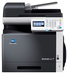
Konica-Minolta bizhub C35
Рейтинг
Снят с производства
Тип устройства
МФУ
Технология печати
лазерная
Макс. формат
A4
Число страниц в месяц
120000
Скорость печати
A4
30
Цветность печати
цветная
Общие характеристики |
|
---|---|
Тип |
лазерный/светодиодный |
Технология печати |
лазерная |
Тип устройства |
МФУ |
Число страниц в месяц |
120 000 |
Факс |
![]() |
Сканер |
![]() |
Копир |
![]() |
Телефон |
|
Печать фотографий |
|
Размещение |
настольный |
Макс. формат |
A4 |
Цветность печати |
цветная |
Область применения |
большой офис |
Принтер |
|
Количество цветов |
4 |
Время разогрева |
45 |
Пигментные чернила |
|
Печать без полей |
|
Двусторонняя печать |
![]() |
Макс, разрешение для ч/б печати |
|
По Y | 600 |
По X | 600 |
Скорость ч/б печати |
|
A4 | 30 |
Время выхода первого отпечатка |
|
Ч/б | 12,9 |
Цветн, | 12,9 |
Копир |
|
Макс, количество копий за цикл |
999 |
Шаг масштабирования |
0,1 |
Время выхода первой копии |
10,1 |
Значение масштаба |
|
Максимальное | 4 |
Минимальное | 0,25 |
Макс, разрешение (ч/б) |
|
По Y | 600 |
По X | 600 |
По X | 400 |
Сканер |
|
Устройство автоподачи оригиналов |
двустороннее |
Макс. формат оригинала |
A4 |
Стандарт TWAIN |
![]() |
Отправка изображения по e-mail |
![]() |
Стандарт WIA |
![]() |
Оттенки серого |
256 |
Тип сканера |
планшетный/протяжный |
Емкость устройства автоподачи оригиналов |
50 |
Макс, размер сканирования |
|
По X | 216 |
По Y | 356 |
Разрешение сканера |
|
По Х | 600 |
По Y | 400 |
Скорость сканирования |
|
Цветн, | 30 |
Ч/б | 30 |
Расходные материалы |
|
Ресурс ч/б картриджа/тонера |
6 000 |
Количество картриджей |
4 |
Ресурс цветного картриджа/тонера |
6 000 |
Ресурс фотобарабана |
30 000 |
Печать на: |
|
CD/DVD |
|
Рулоне |
|
Карточках |
![]() |
Пленках |
![]() |
Матовой бумаге |
![]() |
Глянцевой бумаге |
![]() |
Конвертах |
![]() |
Этикетках |
![]() |
Плотность бумаги |
|
Максимальная | 210 |
Минимальная | 60 |
Факс |
|
PC Fax |
![]() |
Макс, скорость передачи данных |
33,6 Кбит/с |
Телефон |
|
Спикерфон |
|
Проводная трубка |
|
Беспроводная трубка |
|
Автоответчик |
|
Caller ID |
|
АОН |
|
Стандарт DECT |
|
Шрифты и языки управления |
|
Языки управления |
|
PCL 5c |
![]() |
![]() |
|
PCL 6 |
![]() |
PCL 5e |
![]() |
PostScript 3 |
![]() |
PostScript |
![]() |
PostScript 2 |
|
PPDS |
|
Количество установленных шрифтов |
|
PostScript | 137 |
PCL | 80 |
Лотки |
|
Емкость лотка ручной подачи |
100 |
Подача бумаги |
|
Максимальная | 1 350 |
Стандартная | 350 |
Вывод бумаги |
|
Стандартный | 250 |
Финишер |
|
Брошюровщик |
|
Сортер |
|
Степлер |
|
Интерфейсы |
|
Версия USB |
2,0 |
Веб-интерфейс |
![]() |
USB |
![]() |
Ethernet (RJ-45) |
![]() |
Инфракрасный порт |
|
RS-232 |
|
Устройство для чтения карт памяти |
|
FireWire (IEEE 1394) |
|
Wi-Fi |
|
Bluetooth |
|
LPT |
|
Память/Процессор |
|
Емкость жесткого диска |
120 |
Объем памяти |
1 536 |
Частота процессора |
800 |
Дополнительная информация |
|
Работа от аккумулятора |
|
Экран |
|
Диагональ дисплея |
4,3 |
Поддержка ОС |
|
DOS |
|
Windows |
![]() |
Linux |
![]() |
Mac OS |
![]() |
Потребляемая мощность |
|
При работе | 1 300 |
Габариты |
|
Вес |
39 |
Глубина |
508 |
Ширина |
530 |
Высота |
550 |
Модули
FUSING SECTION
MAIN DRIVE SECTION
PAPER FEED DRIVE SECTION
TRANSFER BELT UNIT
TONER BOTTLE DRIVE SECTION
CASSETTE SECTION
High Voltage Section
ELECTRICAL COMPONENTS
POWER SUPPLY SECTION
PRINT HEAD SECTION
TRANSFER GUIDE SECTION
Vertical conveyance Section
DUP RIVERSE DRIVE SECTION
ADF, IR SECTION
EXTERNAL PARTS
Детали DUP RIVERSE DRIVE SECTION
Деталь: | Label JAM |
Парткод: | A0VD 9491 00 |
Деталь: | GUIDE |
Парткод: | A121 9025 00 |
Деталь: | Label Caution /JAM |
Парткод: | A121 9483 00 |
Деталь: | TORSION COIL SPRING |
Парткод: | A0VD 8924 00 |
Деталь: | GUIDE |
Парткод: | A0VD 9081 01 |
Деталь: | PAPER EXIT ROLLER |
Парткод: | A0VD 8901 02 |
Деталь: | Gear 38/40T |
Парткод: | A0VD 8908 00 |
Деталь: | Paper exit Holder |
Парткод: | A121 8903 02 |
Деталь: | Paper exit Holder |
Парткод: | A121 8953 02 |
Деталь: | ACTUATOR |
Парткод: | A121 8912 00 |
Деталь: | SPRING |
Парткод: | A0VD 8902 00 |
Деталь: | PHOTO INTERRUPTER |
Парткод: | 9335 1300 61 |
Деталь: | Paper exit Roll |
Парткод: | A0VD 8903 01 |
Деталь: | SEAL |
Парткод: | A0VD 1031 00 |
Деталь: | ACTUATOR |
Парткод: | A0VD 9073 00 |
Деталь: | LEVER |
Парткод: | A121 8930 02 |
Деталь: | Fusing Unit 100V |
Парткод: | A148 001 |
Деталь: | FUSING UNIT 120V |
Парткод: | A148 011 |
Деталь: | FUSING UNIT 230V |
Парткод: | A148 021 |
Деталь: | SEAL |
Парткод: | A121 1026 00 |
Деталь: | SEAL |
Парткод: | A0VD 9072 01 |
Деталь: | Brushless motor |
Парткод: | AOVD M100 00 |
Деталь: | COMPRESSING COIL SPRING |
Парткод: | AOVD 2203 00 |
Деталь: | BUSHING |
Парткод: | AOVD 2202 01 |
Деталь: | GEAR 20T |
Парткод: | AOVD 2198 00 |
Деталь: | HOLD PLATE |
Парткод: | AOVD 2113 03 |
Деталь: | Brushless motor |
Парткод: | A0VD M102 00 |
Деталь: | BEARING |
Парткод: | A00F 2139 00 |
Деталь: | Mounting Plate /A |
Парткод: | A0VD 2485 01 |
Деталь: | CLUTCH |
Парткод: | A011 M200 00 |
Деталь: | PIN |
Парткод: | 4036 3014 01 |
Деталь: | Gear 21T |
Парткод: | A0VD 2183 01 |
Деталь: | PAPER FEED DRIVE ASSY |
Парткод: | A0VD R701 11 |
Деталь: | CLUTCH |
Парткод: | A02E M200 00 |
Деталь: | GEAR 22T |
Парткод: | A0VD 2312 00 |
Деталь: | GEAR 25T |
Парткод: | A0VD 2309 01 |
Деталь: | GEAR 20T |
Парткод: | A0VD 2333 01 |
Деталь: | PHOTO INTERRUPTER |
Парткод: | 9335 1300 61 |
Деталь: | LEVER |
Парткод: | A0VD 6241 00 |
Деталь: | HOLDER |
Парткод: | 4002 3123 03 |
Деталь: | Paperfeed Wiring /1 |
Парткод: | A121 N10D 01 |
Деталь: | Power supply Wiring /3 |
Парткод: | A121 N103 00 |
Деталь: | HOLDER |
Парткод: | A0VD 1117 00 |
Деталь: | COMPRESSING COIL SPRING |
Парткод: | A0VD 1116 00 |
Деталь: | TORSION COIL SPRING |
Парткод: | A0VD 1141 01 |
Деталь: | Torsion Coil spring /Rear |
Парткод: | A0VD 1105 00 |
Деталь: | TRANSFER UNIT |
Парткод: | A148 0Y1 |
Деталь: | RAIL /FRONT |
Парткод: | A0VD 1101 04 |
Деталь: | CONTACT |
Парткод: | A0VD 1368 00 |
Деталь: | Torsion Coil spring /Front |
Парткод: | A0VD 1104 00 |
Деталь: | Hold Holder /ASSY |
Парткод: | A0VD 1341 00 |
Деталь: | RAIL |
Парткод: | A0VD 1111 02 |
Деталь: | RAIL |
Парткод: | A0VD 1112 03 |
Деталь: | Photoconductor Wiring /1 |
Парткод: | A121 N10A 00 |
Деталь: | Holder /Front |
Парткод: | A0VD 1114 02 |
Деталь: | SHUTTER |
Парткод: | A0VD 3623 00 |
Деталь: | SEAL |
Парткод: | A0VD 3622 01 |
Деталь: | SEAL |
Парткод: | A0VD 3624 00 |
Деталь: | PULLING COIL SPRING |
Парткод: | A0VD 3625 00 |
Деталь: | RAIL /REAR |
Парткод: | A0VD 1102 05 |
Деталь: | DUCT |
Парткод: | A0VD 1115 02 |
Деталь: | SEAL |
Парткод: | A0VD 1151 00 |
Деталь: | SEAL |
Парткод: | A0VD 1153 01 |
Деталь: | SEAL |
Парткод: | A0VD 1152 00 |
Деталь: | MOUNTING PLATE |
Парткод: | A0VD 2147 00 |
Деталь: | SEAL |
Парткод: | A0VD 3637 00 |
Деталь: | LABEL |
Парткод: | 4129 7345 00 |
Деталь: | SEAL |
Парткод: | A0VD 1154 00 |
Деталь: | Protection Seal |
Парткод: | A0VD 1343 00 |
Деталь: | GEAR 29T |
Парткод: | A0VD 2364 00 |
Деталь: | GEAR 25T |
Парткод: | A0VD 2366 01 |
Деталь: | Drive Holder |
Парткод: | A0VD 2369 02 |
Деталь: | PHOTO INTERRUPTER |
Парткод: | 9335 1300 61 |
Деталь: | SHAFT |
Парткод: | A0VD 2365 00 |
Деталь: | Toner bottle Drive Assy |
Парткод: | A121 R700 00 |
Деталь: | CLUTCH |
Парткод: | A0VD M200 00 |
Деталь: | STOPPER |
Парткод: | A0VD 2374 00 |
Деталь: | GEAR 20T |
Парткод: | A0VD 2378 00 |
Деталь: | Relay Wiring |
Парткод: | A121 N121 01 |
Деталь: | GROUND PLATE |
Парткод: | A121 1912 01 |
Деталь: | Label Position |
Парткод: | A0VD 4900 01 |
Деталь: | BUSHING |
Парткод: | 4131 3003 01 |
Деталь: | CLUTCH |
Парткод: | 4030 3034 01 |
Деталь: | ROLLER |
Парткод: | 4138 3032 02 |
Деталь: | ROLLER ASSY |
Парткод: | 4658 0151 06 |
Деталь: | HOLDER |
Парткод: | A0VD 6211 00 |
Деталь: | PRESSURE SPRING |
Парткод: | 4138 3254 01 |
Деталь: | GUIDE PLATE |
Парткод: | 4131 3056 01 |
Деталь: | GUIDE |
Парткод: | 4131 3057 02 |
Деталь: | Regulating Part |
Парткод: | A121 6208 00 |
Деталь: | REGULATING PLATE |
Парткод: | A0VD 6231 01 |
Деталь: | MOUNTING PLATE |
Парткод: | A0VD 6232 00 |
Деталь: | Label 2 |
Парткод: | A121 9432 00 |
Деталь: | CASSETTE ASSY |
Парткод: | A121 R701 00 |
Деталь: | Label Prohibition inkjet media |
Парткод: | 4138 7316 01 |
Деталь: | SPACER |
Парткод: | A0VD 1090 01 |
Деталь: | HIGH VOLTAGE UNIT |
Парткод: | A121 M402 00 |
Деталь: | HV Flatcable |
Парткод: | A121 N10H 01 |
Деталь: | Duct 12 |
Парткод: | AOVD 1394 01 |
Деталь: | SEAL |
Парткод: | A1211013 00 |
Деталь: | SEAL |
Парткод: | AOVD 1395 00 |
Деталь: | MOUNTING PLATE |
Парткод: | A121 1302 01 |
Деталь: | Hold Holder |
Парткод: | A0VD 1361 00 |
Деталь: | Paperfeed Wiring /2 |
Парткод: | A121 N10E 01 |
Деталь: | Shield Case |
Парткод: | A121 1007 01 |
Деталь: | Shield Case |
Парткод: | A121 1319 01 |
Деталь: | AC Wiring /2 |
Парткод: | A121 N100 00 |
Деталь: | ROCKER SWITCH |
Парткод: | A034 M602 00 |
Деталь: | RUBBER FOOT |
Парткод: | A121 1012 00 |
Деталь: | SEAL |
Парткод: | A121 1324 01 |
Деталь: | AC Wiring /1 |
Парткод: | A0VD N100 01 |
Деталь: | PWB Assembly (bizhub JP) |
Парткод: | A121 H013 02 |
Деталь: | PWB Asssembly (bizhub) |
Парткод: | A121 H012 0D |
Деталь: | Controller Flatcable /1 |
Парткод: | A121 N10K 01 |
Деталь: | PWB-Assembly(PWB-Assy) |
Парткод: | A121 H001 0A |
Деталь: | SEAL |
Парткод: | A121 1023 00 |
Деталь: | SEAL |
Парткод: | A121 1024 00 |
Деталь: | FERRITE CORE |
Парткод: | 9326 1910 31 |
Деталь: | ACCESSORY CONNCTORS |
Парткод: | V819 3000 16 |
Деталь: | FAX Assembly (JP) |
Парткод: | A121 H016 07 |
Деталь: | FAX Assembly (WW) |
Парткод: | A121 H015 07 |
Деталь: | Relay Wiring |
Парткод: | A121 N122 02 |
Деталь: | COVER |
Парткод: | A121 1315 01 |
Деталь: | COVER |
Парткод: | A121 1011 02 |
Деталь: | SHIELD PLATE |
Парткод: | A121 1308 01 |
Деталь: | Relay harness |
Парткод: | A0VD N123 00 |
Деталь: | Relay harness |
Парткод: | A0VD N122 00 |
Деталь: | Base Plate Support Rubber |
Парткод: | 13KK 7306 0 |
Деталь: | HDD |
Парткод: | A0VD M716 00 |
Деталь: | WASHER |
Парткод: | A0FD 1532 00 |
Деталь: | SHOULDER SCREW |
Парткод: | A121 1322 00 |
Деталь: | SHIELD PLATE |
Парткод: | A121 1321 00 |
Деталь: | SHOULDER SCREW |
Парткод: | 4139 2328 01 |
Деталь: | Relay Wiring |
Парткод: | A121 N123 01 |
Деталь: | FERRITE CORE |
Парткод: | 9326 1810 21 |
Деталь: | Power supply Wiring /2 |
Парткод: | A121 N102 00 |
Деталь: | SEAL |
Парткод: | A121 1022 00 |
Деталь: | SEAL |
Парткод: | A121 1025 00 |
Деталь: | Ferritecore /1 |
Парткод: | A11P M701 00 |
Деталь: | FAN MOTOR |
Парткод: | 4139 M100 00 |
Деталь: | DUCT |
Парткод: | A121 1001 02 |
Деталь: | HOLDER |
Парткод: | A121 1370 00 |
Деталь: | Protection Cover |
Парткод: | A121 1041 01 |
Деталь: | Detecting Part |
Парткод: | A0VD 1355 00 |
Деталь: | PHOTO INTERRUPTER |
Парткод: | 9335 1300 61 |
Деталь: | Hold Holder |
Парткод: | A0VD 1353 03 |
Деталь: | Adjusting Spring |
Парткод: | A0VD 1352 01 |
Деталь: | TORSION COIL SPRING |
Парткод: | A0VD 1354 02 |
Деталь: | MICRO SWITCH |
Парткод: | 9J06 M601 00 |
Деталь: | PHOTOINTERRUPTER |
Парткод: | A0VD M502 00 |
Деталь: | Power supply /100V |
Парткод: | A121 M400 02 |
Деталь: | Power supply /230V |
Парткод: | A121 M401 02 |
Деталь: | SPACER |
Парткод: | V502 0100 21 |
Деталь: | DUCT |
Парткод: | A121 1004 00 |
Деталь: | COVER |
Парткод: | A121 1317 01 |
Деталь: | SEAL |
Парткод: | A121 1003 00 |
Деталь: | FERRITECORE |
Парткод: | A121 M701 00 |
Деталь: | FERRITECORE |
Парткод: | A121 M700 00 |
Деталь: | SPEAKER |
Парткод: | A121 M715 00 |
Деталь: | Toner Wiring /2 |
Парткод: | A121 N108 00 |
Деталь: | SEAL |
Парткод: | A121 1002 00 |
Деталь: | Insulating sheet |
Парткод: | A121 1325 00 |
Деталь: | SEAL |
Парткод: | A121 1026 00 |
Деталь: | SEAL |
Парткод: | A0VD 1397 00 |
Деталь: | LD Wiring /1 |
Парткод: | A121 N10G 00 |
Деталь: | LD Flatcable /1 |
Парткод: | A121 N10J 01 |
Деталь: | PRINT HEAD ASSY |
Парткод: | A1AR R700 00 |
Деталь: | RAIL |
Парткод: | A0VD 1113 02 |
Деталь: | RUBBER FOOT |
Парткод: | A121 1012 00 |
Деталь: | GEAR 16T |
Парткод: | A0VD 2357 00 |
Деталь: | GEAR 16T |
Парткод: | A0VD 2354 00 |
Деталь: | Gear 16/26T |
Парткод: | A0VD 2356 00 |
Деталь: | Gear 22/30T |
Парткод: | A0VD 2359 00 |
Деталь: | GEAR 16/16T |
Парткод: | A0VD 2355 00 |
Деталь: | TORSION COIL SPRING |
Парткод: | A0VD 3627 02 |
Деталь: | LEVER |
Парткод: | A0VD 3626 02 |
Деталь: | Drive Holder |
Парткод: | A0VD 2351 01 |
Деталь: | COVER |
Парткод: | A121 1087 01 |
Деталь: | Hold Holder |
Парткод: | A0VD 1367 01 |
Деталь: | SOLID STATE SWITCH |
Парткод: | 9335 1400 51 |
Деталь: | Waste Toner Bottle |
Парткод: | A1AU 0Y1 |
Деталь: | SPACER |
Парткод: | A0VD 1090 01 |
Деталь: | GUIDE |
Парткод: | A0VD 7064 00 |
Деталь: | CONTACT |
Парткод: | A0VD 7063 00 |
Деталь: | Photo sensing |
Парткод: | A0VD M500 00 |
Деталь: | HOLDER |
Парткод: | A0VD 7065 00 |
Деталь: | Sensor Wiring /3 |
Парткод: | A121 N106 00 |
Деталь: | TORSION COIL SPRING |
Парткод: | A0VD 7062 01 |
Деталь: | COVER |
Парткод: | A0VD 7061 01 |
Деталь: | Sensor Wiring /2 |
Парткод: | A121 N105 00 |
Деталь: | HUMIDITY SENSOR |
Парткод: | A0VD M501 00 |
Деталь: | GUIDE |
Парткод: | A0VD 7073 03 |
Деталь: | TORSION COIL SPRING |
Парткод: | A0VD 7072 00 |
Деталь: | ACTUATOR |
Парткод: | A0VD 7071 01 |
Деталь: | PHOTO INTERRUPTER |
Парткод: | 9335 1300 61 |
Деталь: | GUIDE |
Парткод: | A0VD 7075 01 |
Деталь: | Manual Feed Tray Unit |
Парткод: | A0VD R716 00 |
Деталь: | TRAY |
Парткод: | A0VD 5617 00 |
Деталь: | FRICTION SHEET |
Парткод: | 4138 3255 01 |
Деталь: | MANUAL PAPER FEED ASSY |
Парткод: | A0VD R713 00 |
Деталь: | GEAR 20T |
Парткод: | A0VD 5613 01 |
Деталь: | GUIDE |
Парткод: | 4131 3057 02 |
Деталь: | GUIDE PLATE |
Парткод: | 4131 3056 01 |
Деталь: | ROLLER |
Парткод: | 4138 3032 02 |
Деталь: | CLUTCH |
Парткод: | 4030 3034 01 |
Деталь: | PRESSURE SPRING |
Парткод: | 4138 3254 01 |
Деталь: | PHOTO INTERRUPTER |
Парткод: | 9335 1300 61 |
Деталь: | ROLLER ASSY |
Парткод: | 4658 0151 06 |
Деталь: | HOLDER |
Парткод: | A0VD 6211 00 |
Деталь: | Open/close Stopper |
Парткод: | A0VD 1623 00 |
Деталь: | Vertical Conveyance Assy |
Парткод: | A121 R702 00 |
Деталь: | Label Prohibition inkjet media |
Парткод: | 4138 7316 01 |
Деталь: | SHAFT |
Парткод: | A0VD 1621 01 |
Деталь: | COMPRESSING SPRING |
Парткод: | A0VD 7017 00 |
Деталь: | 2nd Transfer Roller |
Парткод: | A148 0Y2 |
Деталь: | COVER |
Парткод: | A121 1606 03 |
Деталь: | Label 1 |
Парткод: | A121 9431 00 |
Деталь: | DUP Transport Assy |
Парткод: | A0VD R717 00 |
Деталь: | CLUTCH |
Парткод: | A0VD M202 01 |
Деталь: | GEAR 16T |
Парткод: | A0VD 2353 01 |
Деталь: | ROLL |
Парткод: | 4138 3528 02 |
Деталь: | BUSHING |
Парткод: | A0VD 7023 00 |
Деталь: | BUSHING |
Парткод: | 4138 3532 02 |
Деталь: | PULLING COIL SPRING |
Парткод: | A0VD 7025 01 |
Деталь: | ROLLER |
Парткод: | A0VD 7021 01 |
Деталь: | ROLLER |
Парткод: | A0VD 7029 02 |
Деталь: | LEVER |
Парткод: | A0VD 7047 00 |
Деталь: | GEAR 32T |
Парткод: | A0VD 7044 00 |
Деталь: | COMPRESSING SPRING |
Парткод: | A034 5638 00 |
Деталь: | Gear 35/42T |
Парткод: | A0VD 7043 00 |
Деталь: | GEAR 35T |
Парткод: | A0VD 7051 01 |
Деталь: | GEAR 15T |
Парткод: | A0VD 7030 01 |
Деталь: | PULLING COIL SPRING |
Парткод: | A0VD 7037 00 |
Деталь: | MOUNTING PLATE |
Парткод: | A0VD 7053 03 |
Деталь: | CLUTCH |
Парткод: | A011 M200 00 |
Деталь: | GEAR 20T |
Парткод: | A0VD 7035 01 |
Деталь: | GEAR 28T |
Парткод: | A0VD 7049 00 |
Деталь: | BUSHING |
Парткод: | A0VD 7024 00 |
Деталь: | GEAR 18T |
Парткод: | A0VD 7052 00 |
Деталь: | SEAL |
Парткод: | A034 2140 00 |
Деталь: | COMPRESSING SPRING |
Парткод: | A034 2134 00 |
Деталь: | PAPERFEED SOLENOID |
Парткод: | A034 M200 00 |
Деталь: | FAN MOTOR |
Парткод: | 9313 1300 51 |
Деталь: | Gear 23T |
Парткод: | A0VD 8228 00 |
Деталь: | GEAR 19T |
Парткод: | A0VD 8227 00 |
Деталь: | GEAR 20T |
Парткод: | A0VD 8231 00 |
Деталь: | TORSION COIL SPRING |
Парткод: | A0VD 8234 00 |
Деталь: | SHAFT |
Парткод: | A0VD 8232 00 |
Деталь: | GEAR 18T |
Парткод: | A0VD 8224 00 |
Деталь: | CLUTCH |
Парткод: | A0VD M200 00 |
Деталь: | ROLL |
Парткод: | A0VD 8202 00 |
Деталь: | Riverse/exit Roller |
Парткод: | A0VD 8201 03 |
Деталь: | GUIDE |
Парткод: | A0VD 8256 00 |
Деталь: | GEAR 14T |
Парткод: | A0VD 8211 00 |
Деталь: | DUP Riverse Drive ASSY |
Парткод: | A121 R703 00 |
Деталь: | CONVEYANCE UNIT |
Парткод: | A121 2701 01 |
Деталь: | LABEL |
Парткод: | A121 9446 00 |
Деталь: | Label Prohibit |
Парткод: | A121 9447 00 |
Деталь: | OPTICAL UNIT |
Парткод: | A121 2601 01 |
Деталь: | CABLE CLAMP |
Парткод: | A121 PP02 00 |
Деталь: | WIRE HARNESS ASSY |
Парткод: | A121 PP01 00 |
Деталь: | UPPER COVER/REAR |
Парткод: | A121 PP00 00 |
Деталь: | Separator Roller Assy |
Парткод: | A0CR PP01 00 |
Деталь: | Separator Pad Assy |
Парткод: | A0CR PP02 00 |
Деталь: | Label CCFL |
Парткод: | A121 9439 00 |
Деталь: | COVER |
Парткод: | A121 1608 01 |
Деталь: | Cover /Rear |
Парткод: | A121 1605 01 |
Деталь: | Cover /Upper |
Парткод: | A121 1609 03 |
Деталь: | Cover /Right rear |
Парткод: | A121 1604 01 |
Деталь: | Operation Relay harness |
Парткод: | A121 N120 00 |
Деталь: | FERRITE CORE |
Парткод: | 9326 1400 21 |
Деталь: | PANEL ASSEMBLY |
Парткод: | A121 M71A 02 |
Деталь: | Sheet English |
Парткод: | A121 9501 00 |
Деталь: | Sheet Simplified Chinese |
Парткод: | A121 9506 00 |
Деталь: | SHEET |
Парткод: | A121 9508 00 |
Деталь: | Sheet Traditional Chinese |
Парткод: | A121 9504 00 |
Деталь: | Cover /Right front |
Парткод: | A121 1603 02 |
Деталь: | COVER |
Парткод: | A0VD 1664 01 |
Деталь: | COVER |
Парткод: | A121 1910 00 |
Деталь: | COVER |
Парткод: | A121 1911 01 |
Деталь: | SHAFT |
Парткод: | A121 1906 00 |
Деталь: | CAM |
Парткод: | A121 1903 01 |
Деталь: | Brake Part |
Парткод: | A121 1913 01 |
Деталь: | Support Plate |
Парткод: | A121 1902 01 |
Деталь: | Panel Support Stake |
Парткод: | A121 G180 00 |
Деталь: | RATCHET |
Парткод: | A121 1904 00 |
Деталь: | RATCHET |
Парткод: | A121 1908 01 |
Деталь: | TORSION COIL SPRING |
Парткод: | A121 1907 01 |
Деталь: | Cover /Front |
Парткод: | A121 1601 05 |
Деталь: | Label bizhub C35 |
Парткод: | A121 9424 00 |
Деталь: | Logo Mark |
Парткод: | A00J 9455 00 |
Деталь: | COVER |
Парткод: | A121 1909 00 |
Деталь: | Cover /Left |
Парткод: | A121 1602 02 |
Деталь: | COVER |
Парткод: | A121 1307 01 |
Деталь: | SHEET |
Парткод: | A0VD 9418 01 |
Деталь: | SEAL |
Парткод: | A121 1020 00 |
Деталь: | SEAL |
Парткод: | A121 1021 00 |
Деталь: | Label Emperon |
Парткод: | A011 9462 00 |
Деталь: | MOUNTING PLATE |
Парткод: | A121 1614 00 |
Коды ошибок
0010
0017
0018
0045
004A
004E
0062
0063
0094
0096
0300
0310
0500
0502
0503
0510
0520
0F52
0F53
0F54
0F55
13DD
13E2
13E3
13F0
3C00 ... 3C10
6751
6790
6791
6792
6793
9401
B116
C023
C025
C026
C027
C050
C051
C060
C072
C080
C900
C907
FFFF
Описание
Error code: | 0010 |
Display: | P MOTOR 1 |
Description: | Network I/F Initialize has not been completed. |
Causes: | Network I/F does not work correctly. Firmware for Network I/F is not installed. |
Remedy: | Check the firmware is installed into Network I/F. Main Board replacement |
Error code: | 0017 |
Display: | P MOTOR 2 |
Description: | Intermediate transport motor malfunction • The intermediate transport motor does not rotate evenly even after the lapse of a given period of time while it is being started. • The motor lock signal remains HIGH for a given period of consecutive time while the intermediate transport motor is being rotated. |
Causes: | • Transport motor (M2) • Printer control board (PRCB) |
Remedy: | 1 Check the M3 connector for proper connection and correct as necessary. 2 Check M3 for proper drive coupling and correct as necessary. 3 Check the MFPB connector for proper connection and correct as necessary. 4 M3 operation check MFPB PJ27MFPB-3 to 7 C-5. 5 Change M3. 6 Change MFPB. 7 Change DCPU. |
Error code: | 0018 |
Display: | D MOTOR 2 |
Description: | Color PC Drum Motor’s failure to turn • The Motor Lock signal remains HIGH for a predetermined continuous period of time while the Motor is turning. |
Causes: | • Developing motor (M1) • Printer control board (PRCB) |
Remedy: | 1 Check the connector of motor for proper connection and correct as necessary. 2 Check the connector of motor for proper drive coupling and correct as necessary. 3 Check the PWB-M connector for proper connection and correct as necessary. 4 M2 operation check PWB-M CNDM3-5 (REM) PWB-M CNDM3-8 (LOCK) C-23. 5 Change PWB-M. |
Error code: | 0045 |
Display: | Scanner fan failure CODE (0045) Turn power off, on |
Description: | Scanner Fan Failure • The Exit Tray Cooling Fan Motor does not rotate evenly even after the lapse of a given period of time while it is being started. • The fan motor lock signal remains HIGH for a given period of consecutive time while the exit tray cooling fan motor is being rotated. |
Causes: | • Engine Control Board, PL13.0.20 • Image Processor Board, PL2.0.4 |
Remedy: | 1 Check the Engine Control Board connector P/J24. Is the connector seated properly? Go to step 2. Reseat the connector. If the problem persists, go to step 2. 2 Clean the Exit Tray Cooling Fan air intake Check the fan for possible overload and correct as necessary. Does the problem persist? Go to step 3. Complete. 3 Replace the Exit Tray Cooling Fan. NOTE During replacement, check if the fan is obstructed and correct if necessary. If the problem persists, replace the fan. Does the problem persist? Go to step 3. Complete. 4 Replace the Image Processor Board. Complete. |
Error code: | 004A |
Display: | Duplex fan failure CODE (004A) Turn power off, on |
Description: | Duplex Unit Fan Failure The Duplex Unit Fan Motor lock signal remains HIGH for a predetermined consecutive period of time while the cooling fan motor remains energized. |
Causes: | • Engine Control Board, PL13.0.20 • Duplex Unit, PL14.1 |
Remedy: | 1 Check the Engine Control Board connector P/J21. Is the connector seated properly? Go to step 2. Reseat the connector. If the problem persists, go to step 2. 2 Replace the Engine Control Board. Does the problem persist? Go to step 3. Complete. 3 Replace the Duplex Unit. Complete. |
Error code: | 004E |
Display: | LVPS fan failure CODE (004E) Turn power off, on |
Description: | LVPS Fan Failure • The Power Supply Cooling Fan Motor does not rotate evenly even after the lapse of a given period of time while it is being started. • The motor lock signal remains HIGH for a given period of consecutive time while the Power Supply Cooling Fan Motor is being rotated. |
Causes: | • Power Supply Cooling Fan Motor, PL12.0.11 • Engine Control Board, PL13.0.20 • Power Supply, PL13.0.17 |
Remedy: | 1 Check the High Voltage Board connectors CN1 and CN2, and the Engine Control Board connector P/J17. Are the connectors seated properly? Go to step 2. Reseat the connector(s). If the problem persists, go to step 2. 2 Check the Power Supply Cooling Fan Motor control signals at CN2. Are the signals operating correctly? Replace the motor. If the problem persists, go to step 3. Go to step 3. 3 Check the Power Supply Cooling Fan Motor control signals at PJ17 on the Engine Control Board. Are the control signals operating correctly? Replace the High Voltage Board. If the problem persists, go to step 4. Go to step 4. 4 On the Engine Control Board, check for +24 VDC at P/J2-1, 5, and 7. Check for +5 VDC at P/J2-2. Are the voltages present and within specification? Go to step 5. Replace the Power Supply. If the problem persists, go to step 5. 5 Replace the Engine Control Board. Complete. |
Error code: | 0062 |
Display: | TRAY3 FEED MOT |
Description: | Tray 3 media feed motor malfunction • The motor lock signal remains HIGH for a given period of consecutive time while the media feed motor is being rotated. |
Remedy: | 1 Check the connector between M1-PCCB PJ3 for proper connection and correct as necessary. 2 Check the connector between PCCB PJ1, PJ2-relay CN53, CN70-PRCB PJ25 for proper connection and correct as necessary. 3 Check the M1 connector for proper drive coupling and correct as necessary. 4 M1 operation check PCCB PJ3-4 to 8 K-2. 5 Change M1. 6 Change PCCB. 7 Change PRCB. |
Error code: | 0063 |
Description: | Tray 4 media feed motor malfunction • The motor lock signal remains HIGH for a given period of consecutive time while the media feed motor is being rotated. |
Remedy: | 1 Check the connector between M1-PCCB PJ3 for proper connection and correct as necessary. 2 Check the connector between PCCB PJ1, PJ2-relay CN53, CN70-PRCB PJ7 for proper connection and correct as necessary. 3 Check the M1 connector for proper drive coupling and correct as necessary. 4 M1 operation check. 5 Change M1. 6 Change PCCB. 7 Change PRCB. |
Error code: | 0094 |
Display: | Trans. roll failure CODE (0094) Turn power off, on |
Description: | Transfer Roll Failure Possible causes: • The 2nd Image Transfer Retraction Position Sensor(PS3) is not activated (retracted position) within a given period of time after the retraction sequence of the 2nd transfer roller has been started. • The 2nd Image Transfer Retraction Position Sensor is not deactivated (pressed position) within a given period of time after the pressure sequence of the 2nd transfer roller has been started. |
Causes: | • 2nd Image Transfer Retraction Position Sensor (PS3), PL4.0.9 • 2nd Image Transfer Retraction Position Solenoid (SD4), PL7.2.23 • Main Motor, PL9.1.6 • Engine Control Board, PL13.0.20 |
Remedy: | 1 Check the Main Motor connector CN37. Is the connector seated properly? Go to step 2. Reseat the connector. If the problem persists, go to step 2. 2 Check the Main Motor for proper drive coupling and correct as necessary. Does the problem persist? Go to step 3. Complete. 3 Check the 2nd Image Transfer Retraction Position Solenoid connector CN5. Is the connector seated properly? Go to step 4. Reseat the connector. If the problem persists, go to step 4. 4 Check the 2nd Image Transfer Retraction Position Solenoid for proper drive coupling and correct as necessary. Does the problem persist? Go to step 5. Complete. 5 Check the 2nd Image Transfer Retraction Position Sensor control signal for a voltage change at P/J12-3 on the Engine Control Board. Is the signal operating correctly? Go to step 6. Replace the Engine Control Board. If the problem persists, go to step 6. 6 Replace the 2nd Image Transfer Retraction Position Solenoid. Does the problem persist? Go to step 7. Complete. 7 Replace the 2nd Image Transfer Retraction Position Sensor. Complete. |
Error code: | 0096 |
Display: | XFER DETACH 1 |
Description: | Transfer Belt Separation • The 1st Image Transfer Pressure/Retraction Position Sensor doesn’t turn ON (Retracting) even after the lapse of a given period of time after the 1st Image Transfer Pressure/Retraction Clutch has turned ON during the Transfer Belt is retracting. • The 1st Image Transfer Pressure/Retraction Position Sensor doesn’t turn OFF (Pressuring) even after the lapse of a given period of time after the 1st Image Transfer Pressure/Retraction Clutch has turned ON during the Transfer Belt is pressuring. |
Causes: | • 1st transfer pressure sensor (PS17) • Transport motor (M2) • 1st transfer pressure solenoid (SD1) • Printer control board (PRCB) |
Remedy: | 1 Check the M1 connector for proper connection and correct as necessary. 2 PC6 I/O check, Sensor check 3 CL3 operation check PWB-M CNDM1-11 (ON) K to L-2. 4 M1 operation check PWB-M CNDM1-5 (REM) PWB-M CNDM1-8 (LOCK) K to L-2. 5 Change PWB-M. |
Error code: | 0300 |
Display: | POLYGON MOTOR |
Description: | Polygon motor malfunction |
Causes: | • The polygon motor does not rotate evenly even after the lapse of a given period of time after it has been started. • The motor lock signal remains HIGH for a given period of consecutive time while the polygon motor is being rotated. |
Remedy: | 1 Check the cable and connector for proper connection and correct as necessary. - - 2 Change PH unit. - - 3 Change PRCB. - - |
Error code: | 0310 |
Display: | LASER ERROR |
Description: | Laser malfunction |
Causes: | • The SOS signal is not detected within a given period of time after the output of the laser has been started. |
Remedy: | 1 Check the cable and connector for proper connection and correct as necessary. - - 2 Change PH unit. - - 3 Change PRCB. - - |
Error code: | 0500 |
Display: | FUSER ERROR |
Description: | Fuser warm-up failure |
Causes: | • The thermistor /1 does not detect the specified temperature and the warm-up cycle is not completed even after the lapse of a given period of time after the cycle has been started. |
Remedy: | 1 Change fuser unit. - - 2 For C110: 1. Main switch is turned ON. 2. Open the top cover. 3. Press the following keys in this order. ROTATE TONER key -ATTENTION key - ATTENTION key - ROTATE TONER key. 4. Main switch is turned OFF/ON. For C130n: 1. Main switch is turned ON. 2. Execute [SERVICE MENU] - [FUSER UNLOCK]. See P.103 - - 3 Change PRCB. - - 4 Change DCPU. - - |
Error code: | 0502 |
Display: | Thermistor failure CODE (0502) Turn power off, on |
Description: | 0502 Thermistor Failure, 0510 Fuser Failure, and 0520 Fuser Failure 0502 Thermistor Failure The temperature detected by the thermistor does not reach an expected level after the warm-up cycle starts. |
Causes: | • Fuser, PL4.0.13 • Engine Control Board, PL13.0.20 • Power Supply, PL13.0.17 |
Remedy: | 1 Check that the Fuser is installed correctly. Does the problem persist? Go to step 2. Complete. 2 Check the Engine Control Board connectors P/J2, P/J3, and P/J6. Are the connectors seated properly? Go to step 3 Reseat the connectors. If the problem persists, go to step 3. 3 Check the Low Voltage Power Supply connectors CN3, CN5, and CN7. Are the connectors seated properly? Go to step 4. Reseat the connectors. If the problem persists, go to step 4. 4 Replace the Fuser (8-9). Does the problem persist? Go to step 5. Complete. 5 Replace the Engine Control Board. Does the problem persist? Go to step 6. Complete. 6 Replace the Power Supply. Complete. |
Error code: | 0503 |
Display: | TERMISTOR2 |
Description: | Thermistor resistance failure |
Causes: | • The difference between the temperature detected by thermistor/1 and that detected by thermistor/2 exceeds a predetermined value. |
Remedy: | 1 Change fuser unit. - - 2 For C110: 1. Main switch is turned ON. 2. Open the top cover. 3. Press the following keys in this order. ROTATE TONER key -ATTENTION key - ATTENTION key - ROTATE TONER key. 4. Main switch is turned OFF/ON. For C130n: 1. Main switch is turned ON. 2. Execute [SERVICE MENU] - [FUSER UNLOCK]. See P.103 - - 3 Change PRCB. - - 4 Change DCPU. - - |
Error code: | 0510 |
Display: | Fuser failure CODE (0510) Turn power off, on |
Description: | 0502 Thermistor Failure, 0510 Fuser Failure, and 0520 Fuser Failure 0510 Fuser Failure The temperature detected by the thermistor remains lower than expected for a given period of time or longer. |
Causes: | • Fuser, PL4.0.13 • Engine Control Board, PL13.0.20 • Power Supply, PL13.0.17 |
Remedy: | 1 Check that the Fuser is installed correctly. Does the problem persist? Go to step 2. Complete. 2 Check the Engine Control Board connectors P/J2, P/J3, and P/J6. Are the connectors seated properly? Go to step 3 Reseat the connectors. If the problem persists, go to step 3. 3 Check the Low Voltage Power Supply connectors CN3, CN5, and CN7. Are the connectors seated properly? Go to step 4. Reseat the connectors. If the problem persists, go to step 4. 4 Replace the Fuser (8-9). Does the problem persist? Go to step 5. Complete. 5 Replace the Engine Control Board. Does the problem persist? Go to step 6. Complete. 6 Replace the Power Supply. Complete. |
Error code: | 0520 |
Display: | Fuser failure CODE (0520) Turn power off, on |
Description: | 0502 Thermistor Failure, 0510 Fuser Failure, and 0520 Fuser Failure 0520 Fuser Failure The temperature detected by the thermistor remains higher than expected for a given period of time or longer. |
Causes: | • Fuser, PL4.0.13 • Engine Control Board, PL13.0.20 • Power Supply, PL13.0.17 |
Remedy: | 1 Check that the Fuser is installed correctly. Does the problem persist? Go to step 2. Complete. 2 Check the Engine Control Board connectors P/J2, P/J3, and P/J6. Are the connectors seated properly? Go to step 3 Reseat the connectors. If the problem persists, go to step 3. 3 Check the Low Voltage Power Supply connectors CN3, CN5, and CN7. Are the connectors seated properly? Go to step 4. Reseat the connectors. If the problem persists, go to step 4. 4 Replace the Fuser (8-9). Does the problem persist? Go to step 5. Complete. 5 Replace the Engine Control Board. Does the problem persist? Go to step 6. Complete. 6 Replace the Power Supply. Complete. |
Error code: | 0F52 |
Display: | TE SENSOR Y |
Description: | Toner level sensor /Y malfunction • An error occurs on the toner level sensor board (TLSB). |
Causes: | • Toner level sensor/Y (PS13) • Printer control board (PRCB) |
Remedy: | 1 Check the TLSB and MFPB for proper connection and correct as necessary. 2 Change TLSB. 3 Change MFPB. |
Error code: | 0F53 |
Display: | TE SENSOR M |
Description: | Toner level sensor /M malfunction • An error occurs on the toner level sensor board (TLSB). |
Causes: | • Toner level sensor/M (PS14) • Printer control board (PRCB) |
Remedy: | 1 Check the TLSB and MFPB for proper connection and correct as necessary. 2 Change TLSB. 3 Change MFPB. |
Error code: | 0F54 |
Display: | TE SENSOR C |
Description: | Toner level sensor /C malfunction • An error occurs on the toner level sensor board (TLSB). |
Causes: | • Toner level sensor/C (PS15) • Printer control board (PRCB) |
Remedy: | 1 Check the TLSB and MFPB for proper connection and correct as necessary. 2 Change TLSB. 3 Change MFPB. |
Error code: | 0F55 |
Display: | TE SENSOR K |
Description: | Toner level sensor /K malfunction • An error occurs on the toner level sensor board (TLSB). |
Causes: | • Toner level sensor/K (PS16) • Printer control board (PRCB) |
Remedy: | 1 Check the TLSB and MFPB for proper connection and correct as necessary. 2 Change TLSB. 3 Change MFPB. |
Error code: | 13DD |
Display: | Initial toner failed CODE (13DD) Replace toner Contact Xerox for unit exchange |
Description: | Initial Toner Failure The printer determines that an initial toner cartridge has been installed. The printer is programmed to only use initial toner cartridges one time. |
Remedy: | Install a Xerox Standard or High Capacity cartridge. |
Error code: | 13E2 |
Display: | Engine ROM failure CODE (13E2) Turn power off, on |
Description: | Engine ROM Failure Flash ROM writing is found faulty during a check. |
Causes: | • Engine Control Board, PL13.0.20 • Image Processor Board, PL2.0.4 |
Remedy: | 1 Check the Engine Control Board connectors. Are the connectors seated properly? Go to step 2. Reseat the connectors. If the problem persists, go to step 2. 2 Replace the Engine Control Board. Does the problem persist? Go to step 3. Complete. 3 Replace the Image Processor Board. Complete. |
Error code: | 13E3 |
Display: | FLASH DEVICE |
Description: | Flash ROM device fault • An erase error occurs during erasing of data in flash ROM. |
Causes: | • Printer control board (PRCB) • MFP board (MFPB) |
Remedy: | 1 Check the MFPB for proper connection and correct as necessary. 2 Change PRCB. 3 Change MFPB. |
Error code: | 13F0 |
Display: | ENGINE ERR |
Description: | Engine control failure |
Causes: | • An undefined malfunction occurs in the engine section (PRCB, etc.). |
Remedy: | 1 Check the cable and connector for proper connection and correct as necessary. - - 2 Change PRCB. - - 3 Change MFPB. |
Error code: | 3C00 ... 3C10 |
Description: | Trouble related to security • Contact the responsible people of KONICA MINOLTA when not returning in power switch OFF/ON. |
Error code: | 6751 |
Description: | CCD clamp/gain adjustment failure During the CCD gain adjustment, a condition in which the peak value of the output data is equal to, or less than, 64 occurs three consecutive times during retries. |
Causes: | • Scanner unit • MFP board (MFPB) |
Remedy: | 1 Check the connector between scanner unit-MFPB CN102, CN103 for proper connection and correct as necessary. - - 2 Check for possible extraneous light and correct as necessary. - - 3 Clean the lens, mirrors, CCD surface, and shading sheet if dirty. - - 4 Correct reflective mirror of the scanner if faulty, or change scanner mirror. - - 5 Replace scanner unit - - 6 Replace MFPB |
Error code: | 6790 |
Description: | AFE offset adjustment error During the offset adjustment, the offset value does not fall within the predetermined range a total of three times including retries. |
Causes: | • Scanner unit • MFP board (MFPB) |
Remedy: | 1 Check the connector between scanner unit-MFPB CN102, CN103 for proper connection and correct as necessary. - - 2 Check for possible extraneous light and correct as necessary. - - 3 Clean the lens, mirrors, CCD surface, and shading sheet if dirty. - - 4 Correct reflective mirror of the scanner if faulty, or change scanner mirror. - - 5 Replace scanner unit - - 6 Replace MFPB |
Error code: | 6791 |
Description: | AFE register setting error There is a mismatch between the set default values of the AFE gain/offset and the gain/offset values read thereafter. |
Causes: | • Scanner unit • MFP board (MFPB) |
Remedy: | 1 Check the connector between scanner unit-MFPB CN102, CN103 for proper connection and correct as necessary. - - 2 Check for possible extraneous light and correct as necessary. - - 3 Clean the lens, mirrors, CCD surface, and shading sheet if dirty. - - 4 Correct reflective mirror of the scanner if faulty, or change scanner mirror. - - 5 Replace scanner unit - - 6 Replace MFPB |
Error code: | 6792 |
Description: | White reference plate search error The black/white edge on the shading plate cannot be detected during initialization. |
Causes: | • Scanner unit • MFP board (MFPB) |
Remedy: | 1 Check the connector between scanner unit-MFPB CN102, CN103 for proper connection and correct as necessary. - - 2 Check for possible extraneous light and correct as necessary. - - 3 Clean the lens, mirrors, CCD surface, and shading sheet if dirty. - - 4 Correct reflective mirror of the scanner if faulty, or change scanner mirror. - - 5 Replace scanner unit - - 6 Replace MFPB |
Error code: | 6793 |
Description: | Scanner communication error A communication error of some sort occurs between the controller and the scanner. |
Causes: | • Scanner unit • MFP board (MFPB) |
Remedy: | 1 Check the connector between scanner unit-MFPB CN102, CN103 for proper connection and correct as necessary. - - 2 Check for possible extraneous light and correct as necessary. - - 3 Clean the lens, mirrors, CCD surface, and shading sheet if dirty. - - 4 Correct reflective mirror of the scanner if faulty, or change scanner mirror. - - 5 Replace scanner unit - - 6 Replace MFPB |
Error code: | 9401 |
Description: | Exposure lamp lighting failure detected The intensity of the lamp is not stabilized within a predetermined period of time during the lamp stabilization check process in a lamp warm-up cycle. |
Causes: | • Scanner unit • MFP board (MFPB) |
Remedy: | 1 Check the connector between scanner unit-MFPB CN102, CN103 for proper connection and correct as necessary. - - 2 Check for possible extraneous light and correct as necessary. - - 3 Clean the lens, mirrors, CCD surface, and shading sheet if dirty. - - 4 Correct reflective mirror of the scanner if faulty, or change scanner mirror. - - 5 Replace scanner unit - - 6 MFPB F102, F105 conduction check - - 7 Replace MFPB |
Error code: | B116 |
Description: | Communication fault between controller and FAX board |
Error code: | C023 |
Description: | Developer unit motor-K locking error: The developer unit motor-K is not rotating normally. |
Causes: | Developer unit motor-K LGC board |
Remedy: | (1) Pull out the EPU tray and perform the output check (03-113) to check if the 3 outputs of the Kdeveloper roller and 3 outputs of the drum cleaner auger are rotating normally. When it is not rotating (2) Is the connector of the K-developer unit motor connected securely? (3) Check if the connector of the K-developer motor is disconnected or the harnesses are open circuited. (4) Check if the K-developer unit motor is abnormal. (5) Check if the drive gear array has any abnormality such as breakage. When it is rotating (6) Check if waste toner is clogged on the waste toner transport path of the K-drum cleaner. (7) Check if the developer material is excessively supplied to the K-developer unit. (8) Check if the drive gear array of the K-developer unit has any abnormality such as breakage. |
Error code: | C025 |
Display: | CONTROLLER ROM |
Description: | Controller ROM error • Lead error of destination setting file is detected during the printer starting. |
Causes: | MFP board (MFPB) |
Error code: | C026 |
Display: | CONTROLLER ROM |
Description: | Memory PCB communication problem • There is no reply after five retries at transmitting. • There is no reply after five retries at receiving. |
Causes: | Poor contact in the connector terminals. Defective main PCB or memory PCB. |
Remedy: | Check the connection of connector CN3 on the main PCB and the connector on memory PCB. Repair or replace if necessary. Replace the main PCB or memory PCB and check for correct operation. |
Error code: | C027 |
Display: | CONTROLLER ROM |
Description: | Controller ROM error • Final check sum error is detected during the printer starting. |
Causes: | MFP board (MFPB) |
Remedy: | 1 Turn OFF the Power Switch of the printer and turn it ON again (Restart of the printer.) 2 Check the PWB-P connector for proper connection and correct as necessary. 3 If this error message is displayed after update of firmware, conduct the firmware update procedures again. 4 Change PWB-P. |
Error code: | C050 |
Display: | HDD ERROR |
Description: | Optional second paper feeder communication problem • Communication fails five times successively. |
Causes: | Paper feeder installed incorrectly. Defective main PCB or drawer main PCB. |
Remedy: | Check the installation state of the paper feeder and adjust it if it is not properly installed. Replace the main PCB or drawer main PCB and check for correct operation. |
Error code: | C051 |
Display: | HDD DISK FULL |
Description: | Optional third paper feeder communication problem • Communication fails five times successively. |
Causes: | Paper feeder installed incorrectly. Defective main PCB or drawer main PCB. |
Remedy: | Check the installation state of the paper feeder and adjust it if it is not properly installed. Replace the main PCB or drawer main PCB and check for correct operation. |
Error code: | C060 |
Display: | UPDATE ERROR |
Description: | Detect hopping Motor lock error |
Causes: | Hopping motor does not rotate nomary. |
Remedy: | Power OFF/ON Turn off the Power of the printer and back on. |
Error code: | C072 |
Description: | Counter not installed • The total counter (TCT) is not installed. |
Remedy: | 1 Reboot the main body. 2 Check the connector between TCT-PRCB PJ13 for proper connection and correct as necessary. 3 Change PRCB.M |
Error code: | C080 |
Description: | Image processing problem • JAM05 is detected twice. |
Causes: | Defective engine PCB. |
Remedy: | Replace the engine PCB and check for correct operation. |
Error code: | C900 |
Description: | Connection error between SYS board and LGC board |
Causes: | LGC board If the problem is not corrected with the replacement of the LGC board, reinstall the removed LGC board and replace the IMG board. IMG board If the problem is still not corrected with the replacement of the IMG board, reinstall the removed IMG board and replace the SYS board. SYS board |
Remedy: | (1) Check if the connector CN423, CN424 on the IMG board and the connector CN319, CN320 on the LGC board are completely inserted. (2) Check if the connector pin between the IMG board (connector CN423, CN424) and the LGC board (connector CN319, CN320) is disconnected. (3) Check if the connector CN422 on the IMG board and the connector CN135 on the SYS board are completely inserted. (4) Check if the connector pin between the IMG board (connector CN422) and the SYS board (connector CN135) is disconnected. (5) Check if the conductor patterns on the IMG board, LGC board and SYS board are short circuited or open circuited. (6) Replace the LGC board if no problem is found in steps from (1) to (5) above. (7) If the problem is not corrected with the replacement of the LGC board, reinstall the removed LGC board and replace the IMG board. (8) If the problem is still not corrected with the replacement of the IMG board, reinstall the removed IMG board and replace the SYS board. |
Error code: | C907 |
Description: | Abnormal end of counter backup • The counter backup process results in an abnormal end due to a write error or other reasons. |
Remedy: | 1 Check the MFPB connector for proper connection and correct as necessary 2 Check the SSDB connector for proper connection and correct as necessary 3 Change MFPB. 4 After taking the above actions, if the counter backup process results in the same trouble code again, the SSD can be broken. In this case, the counter backup is unavailable. |
Error code: | FFFF |
Display: | I/F COMM ERROR |
Description: | Interface Communication error • Correct communication is failed when receiving/sending the command between PWB-A and PWB-P. |
Causes: | Print control board (PRCB) MFP board (MFPB) |
Remedy: | 1 Turn OFF the Power Switch of the printer and turn it ON again (Restart of the printer.) 2 Check the PWB-P connector for proper connection and correct as necessary 3 Check the PWB-M connector for proper connection and correct as necessary. 4 Change PWB-M. |