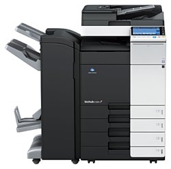
Konica-Minolta bizhub C364
Рейтинг

 Снят с производства
Тип устройства
МФУ
Технология печати
лазерная
Макс. формат
A3
Число страниц в месяц
125000
Скорость печати
A4
36
Цветность печати
цветная
Общие характеристики |
|
|---|---|
Технология печати |
лазерная |
Тип |
лазерный/светодиодный |
Сканер |
|
Копир |
|
Макс. формат |
A3 |
Область применения |
большой офис |
Размещение |
напольный |
Телефон |
|
Цветность печати |
цветная |
Печать фотографий |
|
Факс |
|
Тип устройства |
МФУ |
Число страниц в месяц |
125 000 |
Принтер |
|
Количество цветов |
4 |
Время разогрева |
20 |
Пигментные чернила |
|
Печать без полей |
|
Двусторонняя печать |
|
Макс, разрешение для ч/б печати |
|
| По X | 1 200 |
| По Y | 1 200 |
Скорость ч/б печати |
|
| A3 | 18 |
| A4 | 36 |
Копир |
|
Шаг масштабирования |
0,1 |
Время выхода первой копии |
5,3 |
Значение масштаба |
|
| Максимальное | 4 |
| Минимальное | 0,25 |
Макс, разрешение (ч/б) |
|
| По X | 600 |
| По Y | 600 |
Сканер |
|
Слайд-адаптер |
|
Емкость устройства автоподачи оригиналов |
100 |
Тип сканера |
планшетный/протяжный |
Макс. формат оригинала |
A3 |
Устройство автоподачи оригиналов |
двустороннее |
Стандарт TWAIN |
|
Отправка изображения по e-mail |
|
Макс, размер сканирования |
|
| По X | 297 |
Разрешение сканера |
|
| По Х | 600 |
Скорость сканирования |
|
| Ч/б | 160 |
| Цветн, | 160 |
Расходные материалы |
|
Ресурс ч/б картриджа/тонера |
27 000 |
Ресурс девелопера |
600 000 |
Количество картриджей |
4 |
Ресурс цветного картриджа/тонера |
25 000 |
Печать на: |
|
| Матовой бумаге |
|
| Карточках |
|
| Пленках |
|
| Этикетках |
|
| Глянцевой бумаге |
|
| Конвертах |
|
| Рулоне |
|
| Фотобумаге |
|
| CD/DVD |
|
Плотность бумаги |
|
| Максимальная | 300 |
| Минимальная | 52 |
Факс |
|
Цветной |
|
Телефон |
|
Беспроводная трубка |
|
Проводная трубка |
|
Стандарт DECT |
|
Автоответчик |
|
Спикерфон |
|
Caller ID |
|
АОН |
|
Шрифты и языки управления |
|
Языки управления |
|
| PostScript 2 |
|
| PostScript |
|
| PCL 5c |
|
| PostScript 3 |
|
|
|
|
| PCL 6 |
|
Количество установленных шрифтов |
|
| PostScript | 137 |
| PCL | 80 |
Лотки |
|
Емкость лотка ручной подачи |
150 |
Подача бумаги |
|
| Максимальная | 3 650 |
| Стандартная | 1 150 |
Вывод бумаги |
|
| Стандартный | 250 |
| Максимальный | 3 200 |
Финишер |
|
Сортер |
|
Степлер |
|
Брошюровщик |
|
Интерфейсы |
|
RS-232 |
|
FireWire (IEEE 1394) |
|
Wi-Fi |
|
Bluetooth |
|
LPT |
|
Инфракрасный порт |
|
Устройство для чтения карт памяти |
|
Версия USB |
2,0 |
Ethernet (RJ-45) |
|
USB |
|
Веб-интерфейс |
|
Память/Процессор |
|
Объем памяти |
2 048 |
Частота процессора |
1 000 |
Емкость жесткого диска |
250 |
Процессор |
PowerPC MPC8536 |
Макс, объем памяти |
4 096 |
Дополнительная информация |
|
Работа от аккумулятора |
|
Диагональ дисплея |
9 |
Экран |
|
Поддержка ОС |
|
| DOS |
|
| Mac OS |
|
| Windows |
|
| Linux |
|
Потребляемая мощность |
|
| При работе | 1 580 |
Габариты |
|
Глубина |
685 |
Высота |
779 |
Ширина |
615 |
Вес |
85 |
Модули
PAPER SIZE DETECTION SECTION
2ND PAPER FEED SECTION
PH UNIT
EXTERNAL PARTS
Main Drive/ Paper Feed Drive Section
CASSETTE RAIL SECTION
Fusing Drive Section
TONER SUPPLY SECTION
IR COVER SECTION
TONER BOTTLE DRIVE SECTION
PAPER EXIT SECTION
REVERSAL UNIT
ELECTRICAL COMPONENTS
ERASE LAMP SECTION
WASTE TONER BOX SECTION
OPERATION PANEL SECTION
2ND CASSETTE SECTION
FUSING SECTION
VERTICAL TRANSPORT SECTION
1ST CASSETTE SECTION
High Voltage Section
OZONE DUCT SECTION
SCANNER SECTION
TRANSFER UNIT
DV LOCK LEVER SECTION
VERTICAL CONVEYANCE DOOR SECTION
PAPER FEED SECTION
CONVEYANCE SECTION
INNER COVER SECTION
MAIN POWER SUPPLY SECTION
BYPASS TRAY SECTION
1ST PAPER FEED SECTION
Детали WASTE TONER BOX SECTION

| Деталь: | Paperfeed Wiring /Rear |
| Парткод: | A161 N10N 01 |
| Деталь: | SHOULDER SCREW |
| Парткод: | A161 6278 01 |
| Деталь: | HOLDER |
| Парткод: | A161 6275 00 |
| Деталь: | HOLDER |
| Парткод: | A161 6280 11 |
| Деталь: | PHOTOINTERRUPTER |
| Парткод: | A161 M506 00 |
| Деталь: | PHOTOINTERRUPTER |
| Парткод: | A161 M505 01 |
| Деталь: | PRESSURE SPRING |
| Парткод: | 4002 3110 02 |
| Деталь: | MOTOR |
| Парткод: | 9J06 M103 00 |
| Деталь: | HOLDER |
| Парткод: | A161 6271 02 |
| Деталь: | HOLDER |
| Парткод: | A161 6273 00 |
| Деталь: | COMPRESSING COIL SPRING |
| Парткод: | A0ED 6276 00 |
| Деталь: | SHOULDER SCREW |
| Парткод: | A161 6277 01 |
| Деталь: | PHOTOINTERRUPTER |
| Парткод: | A108 M501 00 |
| Деталь: | REINFORCE PLATE |
| Парткод: | A161 5610 00 |
| Деталь: | DRIVE ROLLER |
| Парткод: | A161 5781 00 |
| Деталь: | Photoreflector |
| Парткод: | A0ED M501 00 |
| Деталь: | GUIDE PLATE |
| Парткод: | A161 5782 00 |
| Деталь: | Conveyance Detection harness |
| Парткод: | A161 N127 01 |
| Деталь: | MOUNTING PLATE |
| Парткод: | A161 5711 00 |
| Деталь: | MOUNTING PLATE |
| Парткод: | A161 5609 00 |
| Деталь: | ACTUATOR |
| Парткод: | A161 5616 00 |
| Деталь: | PHOTOINTERRUPTER |
| Парткод: | A108 M501 00 |
| Деталь: | Paper feed Frame |
| Парткод: | A161 5603 00 |
| Деталь: | GROUND PLATE |
| Парткод: | A161 5606 00 |
| Деталь: | BALL BEARING |
| Парткод: | A00J 6179 00 |
| Деталь: | COMPRESSING COIL SPRING |
| Парткод: | A161 5628 00 |
| Деталь: | SHAFT |
| Парткод: | A161 5605 00 |
| Деталь: | GEAR 26T |
| Парткод: | A161 5624 00 |
| Деталь: | BUSHING |
| Парткод: | A00J 6632 00 |
| Деталь: | BUSHING |
| Парткод: | 4131 3003 01 |
| Деталь: | ROLLER |
| Парткод: | A00J 5636 00 |
| Деталь: | SHAFT STOPPER 4 |
| Парткод: | 56AA 4049 0 |
| Деталь: | CLUTCH |
| Парткод: | A02E 5611 00 |
| Деталь: | GEAR 34T |
| Парткод: | A161 5623 00 |
| Деталь: | GEAR 28T |
| Парткод: | A161 5626 00 |
| Деталь: | SHAFT |
| Парткод: | A161 5620 00 |
| Деталь: | BUSHING |
| Парткод: | A161 5625 00 |
| Деталь: | HOLDER |
| Парткод: | A161 5621 01 |
| Деталь: | TORSION SPRING |
| Парткод: | A161 5674 00 |
| Деталь: | LEVER |
| Парткод: | A161 5673 00 |
| Деталь: | SHAFT |
| Парткод: | A02E 5608 00 |
| Деталь: | CLUTCH |
| Парткод: | A02E M202 00 |
| Деталь: | CLUTCH |
| Парткод: | A02E M200 00 |
| Деталь: | Paperfeed Wiring /2 |
| Парткод: | A161 N10Q 02 |
| Деталь: | Paperfeed Wiring /2 |
| Парткод: | A4FM N103 02 |
| Деталь: | COMPRESSING COIL SPRING |
| Парткод: | A161 5630 00 |
| Деталь: | CUSHION |
| Парткод: | A161 5787 00 |
| Деталь: | HOLDER |
| Парткод: | A161 5631 00 |
| Деталь: | TORSION COIL SPRING |
| Парткод: | A161 5688 00 |
| Деталь: | GUIDE |
| Парткод: | A161 5785 00 |
| Деталь: | GUIDE |
| Парткод: | A161 5635 01 |
| Деталь: | TORQUE LIMITER |
| Парткод: | A0ED 5639 00 |
| Деталь: | GUIDE PLATE |
| Парткод: | A161 5784 01 |
| Деталь: | TORSION COIL SPRING |
| Парткод: | A161 5687 00 |
| Деталь: | SHAFT |
| Парткод: | A161 5634 00 |
| Деталь: | MOUNTING PLATE |
| Парткод: | A161 5640 01 |
| Деталь: | PRESSURE SPRING |
| Парткод: | 4030 3017 03 |
| Деталь: | SHAFT |
| Парткод: | A161 5633 00 |
| Деталь: | MOUNTING PLATE |
| Парткод: | A161 5639 01 |
| Деталь: | SHOULDER SCREW |
| Парткод: | 4532 3410 01 |
| Деталь: | PULLING COIL SPRING |
| Парткод: | A161 5644 00 |
| Деталь: | SPACER |
| Парткод: | A161 5642 00 |
| Деталь: | LEVER |
| Парткод: | A161 5641 00 |
| Деталь: | SPACER |
| Парткод: | A161 5643 00 |
| Деталь: | SEPARATION ROLLER ASSY |
| Парткод: | A161 R725 00 |
| Деталь: | DUCT |
| Парткод: | A161 1402 00 |
| Деталь: | FAN MOTOR |
| Парткод: | 4139 M100 00 |
| Деталь: | SCREW |
| Парткод: | 4163 5293 01 |
| Деталь: | GUIDE |
| Парткод: | A161 1353 00 |
| Деталь: | POSITIONING PLATE |
| Парткод: | A161 1054 00 |
| Деталь: | PWB Assembly(PWB-FR ASSY) |
| Парткод: | A161 H005 01 |
| Деталь: | MOUNTING PLATE |
| Парткод: | A161 1018 02 |
| Деталь: | MOUNTING PLATE |
| Парткод: | A161 1303 01 |
| Деталь: | PWB Assembly(PWB-VD2 ASSY) |
| Парткод: | A161 H008 00 |
| Деталь: | HOLDER |
| Парткод: | A161 1378 02 |
| Деталь: | Flatcable /25 |
| Парткод: | A161 N119 01 |
| Деталь: | PRINT HEAD ASSY |
| Парткод: | A161 R709 00 |
| Деталь: | PRINT HEAD ASSY |
| Парткод: | A4FK R700 00 |
| Деталь: | DUCT |
| Парткод: | A161 1474 01 |
| Деталь: | TRAY |
| Парткод: | A161 1610 00 |
| Деталь: | Cover /Upper |
| Парткод: | A161 1601 03 |
| Деталь: | SEAL |
| Парткод: | A0ED 1630 00 |
| Деталь: | SHAFT STOPPER 4 |
| Парткод: | 56AA 4049 0 |
| Деталь: | Indicating Wiring |
| Парткод: | A161 N10K 00 |
| Деталь: | COVER |
| Парткод: | A161 1604 02 |
| Деталь: | PWB Assembly LED1 |
| Парткод: | A00J H00D 00 |
| Деталь: | COVER |
| Парткод: | A161 1603 00 |
| Деталь: | MAGNET CATCH |
| Парткод: | 4475 2603 02 |
| Деталь: | Open/close Cover /Front |
| Парткод: | A161 1613 01 |
| Деталь: | Open/close Cover /Front |
| Парткод: | A161 1602 04 |
| Деталь: | Label bizhub C364 |
| Парткод: | A161 9401 01 |
| Деталь: | Label bizhub C284 |
| Парткод: | A4FK 9401 01 |
| Деталь: | Label bizhub C224 |
| Парткод: | A4FM 9401 01 |
| Деталь: | LABEL |
| Парткод: | A4FK 9403 00 |
| Деталь: | LABEL |
| Парткод: | A4FM 9403 00 |
| Деталь: | Logo Mark |
| Парткод: | A00J 9455 00 |
| Деталь: | LABEL |
| Парткод: | A161 9404 00 |
| Деталь: | CLEANING MATERIAL |
| Парткод: | A161 R704 00 |
| Деталь: | Support Shaft |
| Парткод: | A161 1656 02 |
| Деталь: | Cover /Left |
| Парткод: | A161 1607 02 |
| Деталь: | Cover /Left |
| Парткод: | A161 1608 01 |
| Деталь: | Label Toner 2 |
| Парткод: | A0ED 9407 00 |
| Деталь: | CUSHION |
| Парткод: | A161 1649 02 |
| Деталь: | FNS Relay harness |
| Парткод: | A161 N10M 04 |
| Деталь: | COVER |
| Парткод: | A161 1621 02 |
| Деталь: | COVER |
| Парткод: | A161 1635 01 |
| Деталь: | COVER |
| Парткод: | A161 1663 00 |
| Деталь: | COVER |
| Парткод: | A161 1606 05 |
| Деталь: | Shield cover |
| Парткод: | A161 1323 02 |
| Деталь: | Regulating Part /Lower |
| Парткод: | A161 1648 00 |
| Деталь: | Regulating Part /Middle |
| Парткод: | A161 1647 02 |
| Деталь: | Regulating Part /Upper |
| Парткод: | A161 1646 00 |
| Деталь: | COVER |
| Парткод: | A161 1618 04 |
| Деталь: | COVER |
| Парткод: | A161 1644 01 |
| Деталь: | COVER |
| Парткод: | A161 1609 02 |
| Деталь: | PULLING COIL SPRING |
| Парткод: | A161 1639 00 |
| Деталь: | MOUNTING PLATE |
| Парткод: | A161 1356 00 |
| Деталь: | COVER |
| Парткод: | A161 1398 00 |
| Деталь: | COVER |
| Парткод: | A161 1612 01 |
| Деталь: | COVER |
| Парткод: | A161 1629 00 |
| Деталь: | COVER |
| Парткод: | A161 1622 01 |
| Деталь: | COVER |
| Парткод: | A161 1628 01 |
| Деталь: | GUIDE |
| Парткод: | A161 1320 00 |
| Деталь: | COVER |
| Парткод: | A161 1664 00 |
| Деталь: | LABEL |
| Парткод: | A2X0 9457 00 |
| Деталь: | LABEL |
| Парткод: | A2X0 9450 00 |
| Деталь: | LABEL |
| Парткод: | A02E 1499 00 |
| Деталь: | Label 220-240V 0.65A |
| Парткод: | A00J 9452 01 |
| Деталь: | GEAR 22T |
| Парткод: | A161 2540 00 |
| Деталь: | GEAR 20T |
| Парткод: | A161 2578 00 |
| Деталь: | MOUNTING PLATE |
| Парткод: | A161 2161 01 |
| Деталь: | BUSHING |
| Парткод: | A161 2102 00 |
| Деталь: | brushless Motor /40 |
| Парткод: | A161 M100 01 |
| Деталь: | GUIDE |
| Парткод: | A161 1347 01 |
| Деталь: | CLUTCH |
| Парткод: | A161 M202 00 |
| Деталь: | HOLD PLATE |
| Парткод: | A161 2539 00 |
| Деталь: | GEAR 26T |
| Парткод: | A161 2536 00 |
| Деталь: | Gear 53T |
| Парткод: | A161 2535 00 |
| Деталь: | Caulking(Hold Plate Paper Feed Driv e2) |
| Парткод: | A161 F211 00 |
| Деталь: | GEAR 38T |
| Парткод: | A161 2531 00 |
| Деталь: | GEAR 19/32T |
| Парткод: | A161 2598 00 |
| Деталь: | Caulking(Hold Plate Paper Feed Driv e2) |
| Парткод: | A161 F212 00 |
| Деталь: | Gear 28/28T |
| Парткод: | A161 2207 00 |
| Деталь: | GEAR 28T |
| Парткод: | A161 2206 00 |
| Деталь: | GEAR 26T |
| Парткод: | A161 2205 00 |
| Деталь: | GEAR 35T |
| Парткод: | A161 2204 00 |
| Деталь: | GEAR 25/27T |
| Парткод: | A161 2202 00 |
| Деталь: | Gear 26/34T |
| Парткод: | A161 2201 00 |
| Деталь: | HOLDER |
| Парткод: | A161 2210 01 |
| Деталь: | REINFORCE PLATE |
| Парткод: | A161 1055 00 |
| Деталь: | Flapper solenoid |
| Парткод: | A161 M203 00 |
| Деталь: | Brushless motor |
| Парткод: | A2XK M103 00 |
| Деталь: | brushless Motor /20 |
| Парткод: | A161 M102 00 |
| Деталь: | MAIN DRIVE ASSY |
| Парткод: | A161 R706 00 |
| Деталь: | PAPER FEED DRIVE ASSY |
| Парткод: | A161 R705 00 |
| Деталь: | TORSION COIL SPRING |
| Парткод: | A161 1043 00 |
| Деталь: | STOPPER |
| Парткод: | A161 1023 00 |
| Деталь: | SHAFT |
| Парткод: | A161 1042 00 |
| Деталь: | LEVER |
| Парткод: | A161 1019 00 |
| Деталь: | REINFORCE PLATE |
| Парткод: | A161 1047 01 |
| Деталь: | MOUNTING PLATE |
| Парткод: | A161 1048 00 |
| Деталь: | RUBBER FOOT |
| Парткод: | 0996 3055 01 |
| Деталь: | RAIL |
| Парткод: | A161 1011 01 |
| Деталь: | SHAFT |
| Парткод: | A161 1058 00 |
| Деталь: | ROLL |
| Парткод: | A161 1039 01 |
| Деталь: | MOUNTING PLATE |
| Парткод: | A161 1044 00 |
| Деталь: | COVER |
| Парткод: | A161 1037 00 |
| Деталь: | ROLL |
| Парткод: | A161 6234 00 |
| Деталь: | SHAFT |
| Парткод: | A161 1052 00 |
| Деталь: | MOUNTING PLATE |
| Парткод: | A161 1016 00 |
| Деталь: | MOUNTING PLATE |
| Парткод: | A161 1017 00 |
| Деталь: | Gear 18/115T |
| Парткод: | A161 2542 00 |
| Деталь: | Gear 18/57T |
| Парткод: | A161 2543 00 |
| Деталь: | Gear 33/55T |
| Парткод: | A161 2544 00 |
| Деталь: | BUSHING |
| Парткод: | A161 2547 00 |
| Деталь: | GEAR 38T |
| Парткод: | A161 2545 00 |
| Деталь: | GEAR 12T |
| Парткод: | A161 1220 02 |
| Деталь: | GEAR 17T |
| Парткод: | A161 1219 00 |
| Деталь: | BUSHING |
| Парткод: | A161 2322 00 |
| Деталь: | Gear 22/23T |
| Парткод: | A161 2288 00 |
| Деталь: | SHAFT |
| Парткод: | A161 2563 00 |
| Деталь: | Caulking(Mounting Plate Fuser Drive2L) |
| Парткод: | A161 F251 02 |
| Деталь: | BUSHING |
| Парткод: | A0ED 2597 00 |
| Деталь: | TORSION COIL SPRING |
| Парткод: | A161 2325 01 |
| Деталь: | BUSHING |
| Парткод: | A161 2323 00 |
| Деталь: | GEAR 18T |
| Парткод: | A161 2307 00 |
| Деталь: | Gear 18/18T |
| Парткод: | A161 2313 01 |
| Деталь: | SHAFT |
| Парткод: | A161 2594 00 |
| Деталь: | GEAR 16T |
| Парткод: | 4038 2580 01 |
| Деталь: | MOUNTING PLATE |
| Парткод: | A161 2588 00 |
| Деталь: | GEAR 26T |
| Парткод: | A0ED 2575 00 |
| Деталь: | COLLAR |
| Парткод: | A161 2324 01 |
| Деталь: | GEAR 16T |
| Парткод: | A161 2287 00 |
| Деталь: | GEAR |
| Парткод: | A161 2546 00 |
| Деталь: | Caulking |
| Парткод: | A161 F109 01 |
| Деталь: | Label M4 |
| Парткод: | A161 9411 00 |
| Деталь: | BUSHING |
| Парткод: | 4025 3572 01 |
| Деталь: | FUSER DRIVE ASSY |
| Парткод: | A161 R707 00 |
| Деталь: | Stepping motor |
| Парткод: | A02E M104 00 |
| Деталь: | brushless Motor /20 |
| Парткод: | A161 M102 00 |
| Деталь: | Caulking(Mounting Plate Fuser DriveL) |
| Парткод: | A161 F250 01 |
| Деталь: | SHAFT |
| Парткод: | A161 2318 00 |
| Деталь: | CLUTCH |
| Парткод: | A161 M201 00 |
| Деталь: | GEAR 27T |
| Парткод: | A161 2306 00 |
| Деталь: | Gear 24/70T |
| Парткод: | A161 2305 00 |
| Деталь: | Gear 22/70T |
| Парткод: | A161 2280 00 |
| Деталь: | Gear 33T |
| Парткод: | A161 2281 00 |
| Деталь: | SHAFT |
| Парткод: | A161 2283 01 |
| Деталь: | PIN B 3X12 |
| Парткод: | 56AA 1747 1 |
| Деталь: | SHAFT |
| Парткод: | A161 2587 00 |
| Деталь: | Gear 26/35T |
| Парткод: | A161 2591 00 |
| Деталь: | Gear 35/45T |
| Парткод: | A161 2592 00 |
| Деталь: | LEVER |
| Парткод: | A161 2286 00 |
| Деталь: | TORSION COIL SPRING |
| Парткод: | A161 2585 01 |
| Деталь: | REINFORCE PLATE |
| Парткод: | A161 1207 01 |
| Деталь: | SEAL |
| Парткод: | A161 4037 01 |
| Деталь: | COVER |
| Парткод: | A161 4020 02 |
| Деталь: | COVER |
| Парткод: | A161 4051 02 |
| Деталь: | COVER |
| Парткод: | A161 4052 02 |
| Деталь: | COVER |
| Парткод: | A161 4053 00 |
| Деталь: | SUCTION PLATE |
| Парткод: | 4038 1014 01 |
| Деталь: | SPACER |
| Парткод: | A161 4039 01 |
| Деталь: | Label Toner 1 |
| Парткод: | A0ED 9406 00 |
| Деталь: | SEAL |
| Парткод: | A161 4025 01 |
| Деталь: | SHUTTER |
| Парткод: | A161 4024 01 |
| Деталь: | SEAL |
| Парткод: | A161 4038 00 |
| Деталь: | SEAL |
| Парткод: | A161 4035 00 |
| Деталь: | SEAL |
| Парткод: | A161 4036 00 |
| Деталь: | SEAL |
| Парткод: | A161 4033 00 |
| Деталь: | SEAL |
| Парткод: | A161 4034 00 |
| Деталь: | COVER |
| Парткод: | A161 4021 01 |
| Деталь: | MOUNTING PLATE |
| Парткод: | A161 1355 02 |
| Деталь: | Seal /1 |
| Парткод: | A161 4040 01 |
| Деталь: | Seal /2 |
| Парткод: | A161 4041 00 |
| Деталь: | Sub Hopper Assy |
| Парткод: | A161 R710 00 |
| Деталь: | Sub Hopper Assy |
| Парткод: | A161 R711 00 |
| Деталь: | Sub Hopper Assy |
| Парткод: | A161 R712 00 |
| Деталь: | Sub Hopper Assy |
| Парткод: | A161 R729 00 |
| Деталь: | Gear 43T |
| Парткод: | A161 4014 00 |
| Деталь: | Gear 17/65T |
| Парткод: | A161 4013 00 |
| Деталь: | GEAR 25T |
| Парткод: | A161 4015 00 |
| Деталь: | GEAR 28T |
| Парткод: | A161 4012 00 |
| Деталь: | GEAR 36T |
| Парткод: | A161 4011 00 |
| Деталь: | GEAR 18T |
| Парткод: | A161 4010 00 |
| Деталь: | BUSHING |
| Парткод: | 4163 5102 01 |
| Деталь: | SEAL |
| Парткод: | 4576 5363 01 |
| Деталь: | HOLDER |
| Парткод: | A161 4031 00 |
| Деталь: | SCREW |
| Парткод: | A161 4001 00 |
| Деталь: | DETECTING PLATE |
| Парткод: | A161 4004 01 |
| Деталь: | Detecting Seal |
| Парткод: | A161 4006 01 |
| Деталь: | Agitating Part |
| Парткод: | A161 4003 00 |
| Деталь: | Agitating Shaft |
| Парткод: | A161 4002 00 |
| Деталь: | Toner Drive harness /K |
| Парткод: | A161 N128 01 |
| Деталь: | Stepping motor |
| Парткод: | A02E M104 00 |
| Деталь: | SEAL |
| Парткод: | 4333 5012 01 |
| Деталь: | BUSHING |
| Парткод: | A161 4030 00 |
| Деталь: | Detecting Actuator |
| Парткод: | A161 4005 01 Old |
| Деталь: | Detecting Actuator |
| Парткод: | A161 4043 00 |
| Деталь: | MOUNTING PLATE |
| Парткод: | A161 4007 01 |
| Деталь: | Toner Detection harness /1 |
| Парткод: | A161 N10F 01 |
| Деталь: | PHOTOINTERRUPTER |
| Парткод: | A108 M501 00 |
| Деталь: | SEAL |
| Парткод: | A161 4032 00 |
| Деталь: | TENSION SPRING |
| Парткод: | 4036 5348 01 |
| Деталь: | SHUTTER |
| Парткод: | A0ED 4010 00 |
| Деталь: | PIN |
| Парткод: | A161 4008 00 |
| Деталь: | SEAL |
| Парткод: | A161 1468 00 |
| Деталь: | Fixing Plate |
| Парткод: | A161 4042 00 |
| Деталь: | Read Cover /Rear |
| Парткод: | A161 1702 03 |
| Деталь: | LABEL |
| Парткод: | A161 9406 02 |
| Деталь: | Label Legal Restiriction |
| Парткод: | A00J 9401 00 |
| Деталь: | LABEL |
| Парткод: | A161 9415 00 |
| Деталь: | Read Cover |
| Парткод: | A161 1707 01 |
| Деталь: | Read Cover |
| Парткод: | A161 1706 01 |
| Деталь: | SHOULDER SCREW |
| Парткод: | A00J 1693 00 |
| Деталь: | Read Cover /Right |
| Парткод: | A161 1704 00 |
| Деталь: | COVER |
| Парткод: | A02E 1677 00 |
| Деталь: | HOLDER |
| Парткод: | A161 1708 00 |
| Деталь: | Scanner Relay harness /100V |
| Парткод: | A161 N11C 01 |
| Деталь: | Read Cover /Front |
| Парткод: | A161 1701 00 |
| Деталь: | Read Cover /Left |
| Парткод: | A161 1703 00 |
| Деталь: | Ground Sheet |
| Парткод: | A161 2821 00 |
| Деталь: | GUIDE |
| Парткод: | A161 2416 00 |
| Деталь: | Stepping motor |
| Парткод: | A02E M104 00 |
| Деталь: | Stepping motor |
| Парткод: | A161 M103 00 |
| Деталь: | Drive Holder |
| Парткод: | A161 2401 00 |
| Деталь: | Gear 65T |
| Парткод: | A161 2406 00 |
| Деталь: | GEAR 29T |
| Парткод: | A161 2405 00 |
| Деталь: | Gear 29/62T |
| Парткод: | A161 2404 00 |
| Деталь: | PRESSURE SPRING |
| Парткод: | 4038 5412 02 |
| Деталь: | JOINT |
| Парткод: | A161 2407 00 |
| Деталь: | Gear 20/42T |
| Парткод: | A161 2409 00 |
| Деталь: | MOUNTING PLATE |
| Парткод: | A161 2415 00 |
| Деталь: | Gear 31T |
| Парткод: | A161 2410 00 |
| Деталь: | SHAFT |
| Парткод: | A161 2412 00 |
| Деталь: | GEAR 17T |
| Парткод: | A161 2414 00 |
| Деталь: | Gear 18/91T |
| Парткод: | A161 2403 00 |
| Деталь: | Toner bottle Drive Assy |
| Парткод: | A161 R708 00 |
| Деталь: | Stepping motor |
| Парткод: | A0ED M103 00 |
| Деталь: | Timing belt 231L |
| Парткод: | A161 8914 01 |
| Деталь: | BELT |
| Парткод: | 4640 3920 01 |
| Деталь: | Paper exit Cover |
| Парткод: | A161 8953 00 |
| Деталь: | COVER |
| Парткод: | A161 1623 02 |
| Деталь: | SHEET |
| Парткод: | A161 8941 00 |
| Деталь: | Neutralizing Brush |
| Парткод: | A161 8940 00 |
| Деталь: | SHOULDER SCREW |
| Парткод: | A0P0 7423 00 |
| Деталь: | GUIDE PART |
| Парткод: | A161 8972 00 |
| Деталь: | ROLL |
| Парткод: | 4004 5903 01 |
| Деталь: | SPRING |
| Парткод: | A161 8924 00 |
| Деталь: | SHAFT |
| Парткод: | 4025 5984 01 |
| Деталь: | ROLLER |
| Парткод: | A161 8954 00 |
| Деталь: | SHOULDER SCREW |
| Парткод: | 1164 2028 01 |
| Деталь: | BUSHING |
| Парткод: | A0ED 8911 00 |
| Деталь: | Ground Contact /Upper |
| Парткод: | A161 8955 02 |
| Деталь: | Ground Contact /Lower |
| Парткод: | A161 8956 00 |
| Деталь: | CUSHION |
| Парткод: | A161 8936 00 |
| Деталь: | Guide Lever |
| Парткод: | A161 8904 01 |
| Деталь: | ROLL |
| Парткод: | A0P0 9011 00 |
| Деталь: | SPRING |
| Парткод: | A161 8921 00 |
| Деталь: | Guide Part /Lower |
| Парткод: | A161 8902 02 |
| Деталь: | COLLAR |
| Парткод: | A0ED 8977 00 |
| Деталь: | PIN |
| Парткод: | 4036 2549 01 |
| Деталь: | SEAL |
| Парткод: | A161 8938 00 |
| Деталь: | BUSHING |
| Парткод: | A161 8910 00 |
| Деталь: | MOUNTING PLATE |
| Парткод: | A161 8923 00 |
| Деталь: | SPRING |
| Парткод: | A161 8920 00 |
| Деталь: | SOLENOID ASSY |
| Парткод: | A161 R726 00 |
| Деталь: | Caulking(Mounting Plate) |
| Парткод: | A161 F890 01 |
| Деталь: | SCREW |
| Парткод: | 4163 5293 01 |
| Деталь: | Paper exit Main body |
| Парткод: | A161 8901 02 |
| Деталь: | REGULATING PLATE |
| Парткод: | A161 8935 00 |
| Деталь: | Pulley 18T |
| Парткод: | A161 8913 01 |
| Деталь: | Fixing Part |
| Парткод: | A161 8929 01 |
| Деталь: | ROLLER |
| Парткод: | A161 8903 00 |
| Деталь: | Paper exit Guide /Lower |
| Парткод: | A161 8952 01 |
| Деталь: | Paper exit Guide /Upper |
| Парткод: | A161 8951 02 |
| Деталь: | Pulley 44T |
| Парткод: | A161 8958 00 |
| Деталь: | GROUND SPRING |
| Парткод: | A161 9002 01 |
| Деталь: | GROUND SPRING |
| Парткод: | A161 9003 00 |
| Деталь: | GROUND SPRING |
| Парткод: | A161 9001 00 |
| Деталь: | Cover /Upper |
| Парткод: | A161 8107 01 |
| Деталь: | SCREW |
| Парткод: | 4163 5293 01 |
| Деталь: | REINFORCE PLATE |
| Парткод: | A161 8161 00 |
| Деталь: | Guide Door /Right |
| Парткод: | A161 8101 02 |
| Деталь: | Cover Door |
| Парткод: | A161 8151 00 |
| Деталь: | Guide Plate /5 |
| Парткод: | A161 8122 00 |
| Деталь: | Roller /C |
| Парткод: | A161 8146 01 |
| Деталь: | Roller /B |
| Парткод: | A161 8137 01 |
| Деталь: | BUSHING |
| Парткод: | A02E 8152 00 |
| Деталь: | Label M5 |
| Парткод: | A161 9461 00 |
| Деталь: | Knob /A |
| Парткод: | A161 8147 00 |
| Деталь: | Swing Holder |
| Парткод: | A161 8156 00 |
| Деталь: | Open/close Claw |
| Парткод: | A161 8157 00 |
| Деталь: | Swing Spring |
| Парткод: | A161 8158 00 |
| Деталь: | Guide Plate /1 |
| Парткод: | A161 8102 00 |
| Деталь: | Bushing /A |
| Парткод: | A161 8133 00 |
| Деталь: | Collar /A |
| Парткод: | A161 8138 00 |
| Деталь: | Gear 22/27T |
| Парткод: | A161 8197 01 |
| Деталь: | Pulley 22T |
| Парткод: | A0ED 8117 00 |
| Деталь: | Drive Belt 156L |
| Парткод: | A161 8190 00 |
| Деталь: | Stepping motor |
| Парткод: | A0ED M102 00 |
| Деталь: | Caulking(Panel Rear) |
| Парткод: | A161 F811 02 |
| Деталь: | Gear 18/26T |
| Парткод: | A161 8196 00 |
| Деталь: | Contact /B |
| Парткод: | A161 8143 00 |
| Деталь: | Cover /B |
| Парткод: | A161 8149 01 |
| Деталь: | Spacer /A |
| Парткод: | A161 8164 00 |
| Деталь: | Guide Plate /3 |
| Парткод: | A161 8104 00 |
| Деталь: | Mounting Plate /3 |
| Парткод: | A161 8144 01 |
| Деталь: | Conveyance Drive harness /Upper |
| Парткод: | A161 N121 00 |
| Деталь: | Mounting Plate /2 |
| Парткод: | A161 8108 01 |
| Деталь: | Roller /1 |
| Парткод: | A161 8106 00 |
| Деталь: | Cushion /A |
| Парткод: | A161 8253 00 |
| Деталь: | Pressing Spring /A |
| Парткод: | A161 8136 00 |
| Деталь: | Holding Part |
| Парткод: | A0ED 8151 00 |
| Деталь: | Idler Roller /A |
| Парткод: | A161 8257 00 |
| Деталь: | Cushion /B |
| Парткод: | A161 8258 00 |
| Деталь: | PHOTOINTERRUPTER |
| Парткод: | A108 M501 00 |
| Деталь: | Bushing /C |
| Парткод: | A161 8195 00 |
| Деталь: | Mounting Plate /4 |
| Парткод: | A161 8251 00 |
| Деталь: | Contact /C |
| Парткод: | A161 8194 00 |
| Деталь: | Bushing /B |
| Парткод: | A161 8145 00 |
| Деталь: | ACTUATOR |
| Парткод: | A161 8132 00 |
| Деталь: | Wiring Part |
| Парткод: | A161 8254 00 |
| Деталь: | Contact /A |
| Парткод: | A161 8142 02 |
| Деталь: | TORSION COIL SPRING |
| Парткод: | A161 8134 00 |
| Деталь: | Cover /A |
| Парткод: | A161 8139 02 |
| Деталь: | Wiring Part /2 |
| Парткод: | A161 8256 00 |
| Деталь: | Mounting Plate /1 |
| Парткод: | A161 8109 00 |
| Деталь: | Spring /D |
| Парткод: | A161 7128 00 |
| Деталь: | ACTUATOR |
| Парткод: | A161 8130 01 |
| Деталь: | TORSION COIL SPRING |
| Парткод: | A161 8131 00 |
| Деталь: | Guide Plate /4 |
| Парткод: | A161 8105 03 |
| Деталь: | Cover /D |
| Парткод: | A161 8255 00 |
| Деталь: | BALL BEARING |
| Парткод: | A0TK 3975 01 |
| Деталь: | BUSHING |
| Парткод: | A161 8250 00 |
| Деталь: | GEAR 18T |
| Парткод: | A161 8192 00 |
| Деталь: | Ground Contact /D |
| Парткод: | A161 8259 01 |
| Деталь: | Cushion /B |
| Парткод: | A161 8260 00 |
| Деталь: | HOLDER |
| Парткод: | A161 1314 00 |
| Деталь: | SPACER |
| Парткод: | A161 1365 00 |
| Деталь: | HOLDER |
| Парткод: | A161 1378 02 |
| Деталь: | Support Shaft |
| Парткод: | A161 1308 01 |
| Деталь: | AC Wiring /100V |
| Парткод: | A161 N100 02 |
| Деталь: | LABEL |
| Парткод: | 9J06 7301 01 |
| Деталь: | MOUNTING PLATE |
| Парткод: | A161 1305 02 |
| Деталь: | MOUNTING PLATE |
| Парткод: | A0ED 1357 00 |
| Деталь: | Power source Cord /100V |
| Парткод: | A0ED N300 02 |
| Деталь: | Power code /120V |
| Парткод: | A1UD N300 01 |
| Деталь: | POWER CORD |
| Парткод: | 9381 4300 31 |
| Деталь: | MOUNTING PLATE |
| Парткод: | A161 1306 03 |
| Деталь: | AC Wiring /120V |
| Парткод: | A161 N101 02 |
| Деталь: | AC Wiring /230V |
| Парткод: | A161 N102 02 |
| Деталь: | Power Supply Wiring |
| Парткод: | A02E N125 12 |
| Деталь: | SHEET |
| Парткод: | A161 1345 00 |
| Деталь: | SHOULDER SCREW |
| Парткод: | A161 1386 01 |
| Деталь: | Shield Case |
| Парткод: | A161 1310 05 |
| Деталь: | MOUNTING PLATE |
| Парткод: | A161 1374 02 |
| Деталь: | MOUNTING PLATE |
| Парткод: | A161 1388 04 |
| Деталь: | COVER |
| Парткод: | A161 1375 01 |
| Деталь: | PWB Assembly(PWB-MC ASSY) |
| Парткод: | A161 H001 08 |
| Деталь: | Flatcable /50 |
| Парткод: | A161 N118 00 |
| Деталь: | PWB Assembly(PWB-MFP ASSY) |
| Парткод: | A161 H021 04 |
| Деталь: | PWB Assembly(PWB-MFP ASSY) |
| Парткод: | A4FM H022 04 |
| Деталь: | SHOULDER SCREW |
| Парткод: | A161 1399 01 |
| Деталь: | BUSHING |
| Парткод: | A0P0 1444 00 |
| Деталь: | SHOULDER SCREW |
| Парткод: | A0P0 1443 00 |
| Деталь: | CABLE |
| Парткод: | A0P0 N151 00 |
| Деталь: | CABLE |
| Парткод: | A0P0 N152 00 |
| Деталь: | HDD |
| Парткод: | A161 M720 00 |
| Деталь: | MOUNTING PLATE |
| Парткод: | A161 1307 00 |
| Деталь: | COVER |
| Парткод: | A161 1395 00 |
| Деталь: | SHOULDER SCREW |
| Парткод: | A161 1376 00 |
| Деталь: | DUCT |
| Парткод: | A161 1401 01 |
| Деталь: | FAN MOTOR |
| Парткод: | A0ED M105 00 |
| Деталь: | Control Relay harness |
| Парткод: | A161 N126 02 |
| Деталь: | Controller Detection harness |
| Парткод: | A161 N11B 00 |
| Деталь: | PHOTOINTERRUPTER |
| Парткод: | A108 M501 00 |
| Деталь: | MOUNTING PLATE |
| Парткод: | A161 1394 00 |
| Деталь: | MEMORY MODULES |
| Парткод: | V865 3000 26 |
| Деталь: | MOUNTING PLATE |
| Парткод: | A161 1322 03 |
| Деталь: | SCREW |
| Парткод: | A161 1379 00 |
| Деталь: | COVER |
| Парткод: | A0ED 1319 00 |
| Деталь: | SHOULDER SCREW |
| Парткод: | A0P0 1491 00 |
| Деталь: | GROUND PLATE |
| Парткод: | A0P0 1459 00 |
| Деталь: | CUSHION |
| Парткод: | A161 1362 00 |
| Деталь: | Light blocking Part |
| Парткод: | A0ED 1055 00 |
| Деталь: | SEAL |
| Парткод: | A161 1073 00 |
| Деталь: | HOLDER |
| Парткод: | A161 1301 01 |
| Деталь: | RAIL |
| Парткод: | A0ED 1054 00 |
| Деталь: | SEAL |
| Парткод: | A161 1028 00 |
| Деталь: | RAIL |
| Парткод: | A161 1056 00 |
| Деталь: | PIN |
| Парткод: | A0ED 1031 00 |
| Деталь: | SEAL |
| Парткод: | A161 1072 00 |
| Деталь: | SEAL |
| Парткод: | A161 1071 00 |
| Деталь: | GUIDE |
| Парткод: | A161 1385 00 |
| Деталь: | Eraser (YMC) Assy |
| Парткод: | A161 R701 00 |
| Деталь: | Eraser (Black) Assy |
| Парткод: | A161 R700 00 |
| Деталь: | SHUTTER |
| Парткод: | A0ED 3631 00 |
| Деталь: | PULLING COIL SPRING |
| Парткод: | A0ED 3632 00 |
| Деталь: | SEAL |
| Парткод: | A0ED 3634 00 |
| Деталь: | PIPE |
| Парткод: | A0ED 3630 00 |
| Деталь: | SEAL |
| Парткод: | A0ED 3633 00 |
| Деталь: | Gear 16/40T |
| Парткод: | A161 2451 00 |
| Деталь: | Gear 20/20T |
| Парткод: | A0ED 2450 00 |
| Деталь: | Gear 16/51T |
| Парткод: | A161 2454 00 |
| Деталь: | Waste Toner Box |
| Парткод: | A4NN WY1 |
| Деталь: | Waste Toner Driva |
| Парткод: | A161 F210 00 |
| Деталь: | Waste Toner Pipe |
| Парткод: | A0ED F360 00 |
| Деталь: | COVER |
| Парткод: | A161 3620 00 |
| Деталь: | PANEL ASSEMBLY |
| Парткод: | A161 M705 03 |
| Деталь: | PANEL ASSEMBLY |
| Парткод: | A161 M706 03 |
| Деталь: | PANEL ASSEMBLY |
| Парткод: | A161 M707 03 |
| Деталь: | PANEL ASSEMBLY |
| Парткод: | A161 M708 00 |
| Деталь: | COVER |
| Парткод: | A161 1909 00 |
| Деталь: | MOUNTING PLATE ASSY |
| Парткод: | A161 R720 00 |
| Деталь: | COVER |
| Парткод: | A161 1626 03 |
| Деталь: | COVER |
| Парткод: | A161 1615 03 |
| Деталь: | COVER |
| Парткод: | A161 1640 00 |
| Деталь: | PWB assembly(PWB-UCN ASSY) |
| Парткод: | A0P0 H025 00 |
| Деталь: | MOUNTING PLATE |
| Парткод: | A161 1380 02 |
| Деталь: | Light blocking Cover |
| Парткод: | A161 1672 00 |
| Деталь: | LENS |
| Парткод: | A161 1670 00 |
| Деталь: | COVER |
| Парткод: | A161 1617 00 |
| Деталь: | LENS |
| Парткод: | A161 1671 00 |
| Деталь: | Light blocking Sheet /2 |
| Парткод: | A161 1674 00 |
| Деталь: | Light blocking Sheet /1 |
| Парткод: | A161 1673 00 |
| Деталь: | PWB Assembly(PWB-LED ASSY) |
| Парткод: | A161 H00U 01 |
| Деталь: | COVER |
| Парткод: | A161 1619 00 |
| Деталь: | MOUNTING PLATE |
| Парткод: | A161 1641 03 |
| Деталь: | COVER |
| Парткод: | A161 1614 01 |
| Деталь: | SPEAKER |
| Парткод: | A0P0 M731 00 |
| Деталь: | MOUNTING PLATE |
| Парткод: | A161 1373 02 |
| Деталь: | COVER |
| Парткод: | A161 1627 03 |
| Деталь: | CABLE |
| Парткод: | A0P0 N153 00 |
| Деталь: | INTERFACE CABLE |
| Парткод: | A161 N156 02 |
| Деталь: | Label Emperon |
| Парткод: | A011 9462 00 |
| Деталь: | SEAL |
| Парткод: | A161 1624 00 |
| Деталь: | GROUND PLATE |
| Парткод: | A161 6221 00 |
| Деталь: | SHEET |
| Парткод: | A161 6262 00 |
| Деталь: | ROLL |
| Парткод: | A161 6234 00 |
| Деталь: | Reinforce Plate /Right |
| Парткод: | A161 6331 01 |
| Деталь: | Label FD |
| Парткод: | A00J 9422 02 |
| Деталь: | LABEL |
| Парткод: | A161 9435 00 |
| Деталь: | LABEL |
| Парткод: | A161 9436 01 |
| Деталь: | LABEL |
| Парткод: | A161 9438 02 |
| Деталь: | HOLDER |
| Парткод: | A161 6263 00 |
| Деталь: | LEVER |
| Парткод: | A161 6365 02 |
| Деталь: | LEVER |
| Парткод: | A161 6266 01 |
| Деталь: | PULLING COIL SPRING |
| Парткод: | A161 6268 00 |
| Деталь: | LENS |
| Парткод: | A161 6260 00 |
| Деталь: | Light blocking Sheet |
| Парткод: | A161 6261 00 |
| Деталь: | Label 2 |
| Парткод: | A161 9432 00 |
| Деталь: | COVER |
| Парткод: | A161 6350 00 |
| Деталь: | COVER |
| Парткод: | A161 6259 00 |
| Деталь: | HANDLE |
| Парткод: | A161 6269 00 |
| Деталь: | COVER |
| Парткод: | A161 6351 03 |
| Деталь: | Reinforce Plate /Left |
| Парткод: | A161 6332 02 |
| Деталь: | 2nd Cassette |
| Парткод: | A161 F630 0C Old |
| Деталь: | 2nd Cassette |
| Парткод: | A161 F630 1G |
| Деталь: | Regulating Plate /Rear |
| Парткод: | A161 6209 03 |
| Деталь: | LABEL MAX LEVEL |
| Парткод: | A161 9437 00 |
| Деталь: | CUSHION |
| Парткод: | A161 6241 00 |
| Деталь: | Lifting Shaft |
| Парткод: | A161 6216 00 |
| Деталь: | RACK |
| Парткод: | A161 6211 00 |
| Деталь: | SHOULDER SCREW |
| Парткод: | A161 6206 00 |
| Деталь: | LABEL |
| Парткод: | A161 9430 00 |
| Деталь: | GEAR |
| Парткод: | A161 6207 01 |
| Деталь: | FRICTION SHEET |
| Парткод: | 4030 3226 01 |
| Деталь: | LIFTING PLATE |
| Парткод: | A161 6204 00 |
| Деталь: | KNOB |
| Парткод: | 4037 3204 01 |
| Деталь: | PULLING COIL SPRING |
| Парткод: | A0ED 6214 00 |
| Деталь: | SCREW |
| Парткод: | 4163 5293 01 |
| Деталь: | LEVER |
| Парткод: | A161 6213 00 |
| Деталь: | Regulating Plate /Front |
| Парткод: | A161 6208 02 |
| Деталь: | LEVER |
| Парткод: | 4030 3206 01 |
| Деталь: | GUIDE |
| Парткод: | A0ED 6202 00 |
| Деталь: | MOUNTING PLATE |
| Парткод: | A161 6219 00 |
| Деталь: | LEVER |
| Парткод: | A161 6314 00 Old |
| Деталь: | LEVER |
| Парткод: | A161 6314 11 |
| Деталь: | PLATE SPRING |
| Парткод: | A161 6218 00 |
| Деталь: | REGULATING PLATE |
| Парткод: | A161 6217 01 |
| Деталь: | ACTUATOR |
| Парткод: | A0ED 6207 01 |
| Деталь: | Paper feed Cassette |
| Парткод: | A161 6301 02 |
| Деталь: | LABEL |
| Парткод: | A02E 9403 00 |
| Деталь: | FAN MOTOR |
| Парткод: | 4139 M100 00 |
| Деталь: | FAN MOTOR |
| Парткод: | 9313 1100 33 |
| Деталь: | SEAL |
| Парткод: | A161 1430 00 |
| Деталь: | DUCT |
| Парткод: | A161 1403 00 |
| Деталь: | MOUNTING PLATE |
| Парткод: | A161 1211 03 |
| Деталь: | DUCT |
| Парткод: | A161 1405 00 |
| Деталь: | Seal /Upper |
| Парткод: | A161 1214 01 |
| Деталь: | DUCT |
| Парткод: | A161 1404 00 |
| Деталь: | SEAL |
| Парткод: | A161 1027 00 |
| Деталь: | Fusing Unit 100V |
| Парткод: | A161 R717 11 |
| Деталь: | FUSING UNIT 120V |
| Парткод: | A161 R718 11 |
| Деталь: | FUSING UNIT 230V |
| Парткод: | A161 R719 22 |
| Деталь: | MOUNTING PLATE |
| Парткод: | A161 1372 02 |
| Деталь: | FILTER |
| Парткод: | A0ED 1469 00 |
| Деталь: | Heater Relay harness /1 |
| Парткод: | A161 N106 02 |
| Деталь: | GROUND PLATE |
| Парткод: | A161 1225 00 |
| Деталь: | Conveyance Wiring |
| Парткод: | A161 N10H 01 |
| Деталь: | SCREW |
| Парткод: | 4163 5293 01 |
| Деталь: | Spring /C |
| Парткод: | A161 7127 00 |
| Деталь: | Ground Spring /A |
| Парткод: | A161 7124 00 |
| Деталь: | Ground Plate /C |
| Парткод: | A161 7111 00 |
| Деталь: | Ground Spring /B |
| Парткод: | A161 7110 00 |
| Деталь: | FIXED POWER RESISTORS |
| Парткод: | V800 5003 00 |
| Деталь: | Ground Plate /A |
| Парткод: | A161 7109 00 |
| Деталь: | ACTUATOR |
| Парткод: | A0ED 7038 00 |
| Деталь: | PHOTOINTERRUPTER |
| Парткод: | A108 M501 00 |
| Деталь: | Holder /A |
| Парткод: | A161 7101 02 |
| Деталь: | Transfer Holder /2 |
| Парткод: | A161 5507 00 |
| Деталь: | Support Plate /Front |
| Парткод: | A161 7118 00 |
| Деталь: | Compressing Coil spring /2 |
| Парткод: | A0ED 5510 00 |
| Деталь: | COMPRESSING COIL SPRING |
| Парткод: | A0ED 5511 00 |
| Деталь: | Fixing Part /Lower |
| Парткод: | A161 7123 00 |
| Деталь: | MOUNTING PLATE |
| Парткод: | A0ED 5509 00 |
| Деталь: | Guide Seal |
| Парткод: | A0ED 5517 00 |
| Деталь: | Ground Spring /C |
| Парткод: | A161 7125 00 |
| Деталь: | MOUNTING PLATE |
| Парткод: | A161 5516 00 |
| Деталь: | Transfer Holder /2 |
| Парткод: | A161 5515 00 |
| Деталь: | Adjusting Plate |
| Парткод: | A161 1041 01 |
| Деталь: | 2nd Image Transfer Rollor Assy |
| Парткод: | A161 R714 00 |
| Деталь: | Neutralizing Part |
| Парткод: | A0ED 5508 00 |
| Деталь: | Vertical Transport Assy |
| Парткод: | A161 R716 22 |
| Деталь: | Pulley 22T |
| Парткод: | A0ED 8117 00 |
| Деталь: | Drive Belt 266L |
| Парткод: | A161 7190 00 |
| Деталь: | Gear 22/23T |
| Парткод: | A161 7091 00 |
| Деталь: | COLLAR |
| Парткод: | A0ED 8119 00 |
| Деталь: | Pressing Spring |
| Парткод: | A161 7112 00 |
| Деталь: | Cover /C |
| Парткод: | A161 7126 00 |
| Деталь: | Bushing /1 |
| Парткод: | A161 7131 00 |
| Деталь: | Roller /A |
| Парткод: | A161 7105 00 |
| Деталь: | Idler Roller /A |
| Парткод: | A161 8257 00 |
| Деталь: | BUSHING |
| Парткод: | A02E 8152 00 |
| Деталь: | Label M6 |
| Парткод: | A161 9464 00 |
| Деталь: | Guide Plate /A |
| Парткод: | A161 7102 02 |
| Деталь: | Label M1 |
| Парткод: | A161 9462 00 |
| Деталь: | Lock Shaft /A |
| Парткод: | A161 7113 00 |
| Деталь: | Spring /D |
| Парткод: | A161 7128 00 |
| Деталь: | ACTUATOR |
| Парткод: | A161 7135 00 |
| Деталь: | Conveyance Spring /B |
| Парткод: | A161 7146 00 |
| Деталь: | Ground Plate /D |
| Парткод: | A161 7120 00 |
| Деталь: | Open/close Lever |
| Парткод: | A161 7116 00 |
| Деталь: | Lock Shaft /B |
| Парткод: | A161 7114 00 |
| Деталь: | Fixing Part |
| Парткод: | A161 7145 00 |
| Деталь: | Spring /B |
| Парткод: | A161 7117 00 |
| Деталь: | Lock Shaft /C |
| Парткод: | A161 7115 00 |
| Деталь: | Ground Plate /E |
| Парткод: | A161 7121 00 |
| Деталь: | MOUNTING PLATE |
| Парткод: | A161 7104 01 |
| Деталь: | PLATE SPRING |
| Парткод: | A0ED 7024 00 |
| Деталь: | Guide Plate /B |
| Парткод: | A161 7103 00 |
| Деталь: | Gear 23T |
| Парткод: | A161 7191 00 |
| Деталь: | Support Plate /Rear |
| Парткод: | A161 7119 00 |
| Деталь: | Ground Spring /D |
| Парткод: | A161 7129 00 |
| Деталь: | CONTACT |
| Парткод: | A161 7148 00 |
| Деталь: | Lock plate |
| Парткод: | A161 8163 00 |
| Деталь: | GROUND PLATE |
| Парткод: | A161 6221 00 |
| Деталь: | SHEET |
| Парткод: | A161 6262 00 |
| Деталь: | ROLL |
| Парткод: | A161 6234 00 |
| Деталь: | Reinforce Plate /Right |
| Парткод: | A161 6231 01 |
| Деталь: | Label FD |
| Парткод: | A00J 9422 02 |
| Деталь: | Label Cd |
| Парткод: | A02E 9415 00 |
| Деталь: | LABEL |
| Парткод: | A161 9438 02 |
| Деталь: | HOLDER |
| Парткод: | A161 6263 00 |
| Деталь: | LEVER |
| Парткод: | A161 6265 02 |
| Деталь: | LEVER |
| Парткод: | A161 6266 01 |
| Деталь: | PULLING COIL SPRING |
| Парткод: | A161 6268 00 |
| Деталь: | LENS |
| Парткод: | A161 6260 00 |
| Деталь: | Light blocking Sheet |
| Парткод: | A161 6261 00 |
| Деталь: | Label 1 |
| Парткод: | A161 9431 00 |
| Деталь: | COVER |
| Парткод: | A161 6250 00 |
| Деталь: | COVER |
| Парткод: | A161 6259 00 |
| Деталь: | HANDLE |
| Парткод: | A161 6269 00 |
| Деталь: | COVER |
| Парткод: | A161 6251 03 |
| Деталь: | Reinforce Plate /Left |
| Парткод: | A161 6233 01 |
| Деталь: | Label FD |
| Парткод: | A02E 9413 00 |
| Деталь: | 1st Cassette |
| Парткод: | A161 F620 0C Old |
| Деталь: | 1st Cassette |
| Парткод: | A161 F620 1G |
| Деталь: | Regulating Plate /Rear |
| Парткод: | A161 6209 03 |
| Деталь: | LABEL MAX LEVEL |
| Парткод: | A161 9437 00 |
| Деталь: | CUSHION |
| Парткод: | A161 6241 00 |
| Деталь: | Lifting Shaft |
| Парткод: | A161 6216 00 |
| Деталь: | RACK |
| Парткод: | A161 6211 00 |
| Деталь: | SHOULDER SCREW |
| Парткод: | A161 6206 00 |
| Деталь: | GEAR |
| Парткод: | A161 6207 01 |
| Деталь: | LABEL |
| Парткод: | A161 9430 00 |
| Деталь: | FRICTION SHEET |
| Парткод: | 4030 3226 01 |
| Деталь: | LIFTING PLATE |
| Парткод: | A161 6204 00 |
| Деталь: | KNOB |
| Парткод: | 4037 3204 01 |
| Деталь: | PULLING COIL SPRING |
| Парткод: | A0ED 6214 00 |
| Деталь: | LEVER |
| Парткод: | A161 6213 00 |
| Деталь: | Regulating Plate /Front |
| Парткод: | A161 6208 02 |
| Деталь: | LEVER |
| Парткод: | 4030 3206 01 |
| Деталь: | GUIDE |
| Парткод: | A0ED 6202 00 |
| Деталь: | MOUNTING PLATE |
| Парткод: | A161 6219 00 |
| Деталь: | LEVER |
| Парткод: | A161 6214 00 Old |
| Деталь: | LEVER |
| Парткод: | A161 6214 11 |
| Деталь: | Paper feed Cassette |
| Парткод: | A161 6201 03 |
| Деталь: | PLATE SPRING |
| Парткод: | A161 6218 00 |
| Деталь: | REGULATING PLATE |
| Парткод: | A161 6217 01 |
| Деталь: | ACTUATOR |
| Парткод: | A0ED 6207 01 |
| Деталь: | SCREW |
| Парткод: | 4163 5293 01 |
| Деталь: | LABEL |
| Парткод: | A02E 9403 00 |
| Деталь: | MOUNTING PLATE |
| Парткод: | A161 1325 04 |
| Деталь: | PWB Assembly(PWB-DC Assy) |
| Парткод: | A161 H00C 02 |
| Деталь: | REINFORCE PLATE |
| Парткод: | A161 1328 00 |
| Деталь: | GUIDE |
| Парткод: | A161 1321 00 |
| Деталь: | HOLDER |
| Парткод: | A161 1377 01 |
| Деталь: | HV Contact Assy |
| Парткод: | A161 R702 00 |
| Деталь: | DV Contact Assy |
| Парткод: | A161 R703 00 |
| Деталь: | HIGH VOLTAGE UNIT |
| Парткод: | A161 M406 01 |
| Деталь: | Neutralizing Wiring |
| Парткод: | A161 N11K 00 |
| Деталь: | Transfer Wiring /2 |
| Парткод: | A161 N113 00 |
| Деталь: | GUIDE |
| Парткод: | A161 1348 00 |
| Деталь: | Charging Wiring /K |
| Парткод: | A161 N12P 01 |
| Деталь: | Charging Wiring /C |
| Парткод: | A161 N12N 01 |
| Деталь: | Charging Wiring /M |
| Парткод: | A161 N12M 01 |
| Деталь: | Charging Wiring /Y |
| Парткод: | A161 N12K 01 |
| Деталь: | THERMISTOR |
| Парткод: | A0P0 M503 00 |
| Деталь: | MOUNTING PLATE |
| Парткод: | A161 1420 00 |
| Деталь: | Duct /2 |
| Парткод: | A161 1415 00 |
| Деталь: | Duct /2 |
| Парткод: | A161 1419 01 |
| Деталь: | CONNECTOR |
| Парткод: | V651 0100 02 |
| Деталь: | OZONE FILTER ASSY |
| Парткод: | A161 R727 00 |
| Деталь: | FAN MOTOR |
| Парткод: | 9313 1000 72 |
| Деталь: | MOUNTING PLATE |
| Парткод: | A161 1422 00 |
| Деталь: | Duct /3 |
| Парткод: | A161 1470 01 |
| Деталь: | Seal /2 |
| Парткод: | A161 1453 00 |
| Деталь: | Seal /1 |
| Парткод: | A161 1452 01 |
| Деталь: | Duct /1 |
| Парткод: | A161 1418 00 |
| Деталь: | SEAL |
| Парткод: | A02E 1173 00 |
| Деталь: | Holding Plate |
| Парткод: | A161 2683 00 |
| Деталь: | ORIGINAL GLASS ASSY |
| Парткод: | A161 R722 00 |
| Деталь: | Holding Plate |
| Парткод: | A161 2682 00 |
| Деталь: | GUIDE |
| Парткод: | A161 2816 00 |
| Деталь: | REGULATING PLATE |
| Парткод: | A00J 2653 00 |
| Деталь: | Scanner Wiring /1 |
| Парткод: | A161 N141 00 |
| Деталь: | TAPE |
| Парткод: | 4036 3075 01 |
| Деталь: | SEAL |
| Парткод: | 4581 1625 01 |
| Деталь: | Lead Switch |
| Парткод: | A1UD M502 00 |
| Деталь: | SEAL |
| Парткод: | A161 2627 00 |
| Деталь: | SEAL |
| Парткод: | A0ED 2625 00 |
| Деталь: | SEAL |
| Парткод: | A161 2630 00 |
| Деталь: | Scanner Wiring /2 |
| Парткод: | A161 N142 00 |
| Деталь: | PHOTOINTERRUPTER |
| Парткод: | A108 M501 00 |
| Деталь: | COVER |
| Парткод: | A161 2622 00 |
| Деталь: | FRAME |
| Парткод: | A161 2619 02 |
| Деталь: | FRAME |
| Парткод: | A161 2620 02 |
| Деталь: | COMPRESSING COIL SPRING |
| Парткод: | A161 2803 00 |
| Деталь: | MOUNTING PLATE |
| Парткод: | A161 2801 01 Old |
| Деталь: | MOUNTING PLATE |
| Парткод: | A161 2801 12 |
| Деталь: | APS Photoreflector |
| Парткод: | A161 M50A 00 |
| Деталь: | Slit Glass Assy |
| Парткод: | A161 R723 00 |
| Деталь: | LEVER |
| Парткод: | A161 2802 11 |
| Деталь: | PWB Assembly(PWB-ID ASSY) |
| Парткод: | A161 H01A 00 |
| Деталь: | SEAL |
| Парткод: | A161 2813 00 |
| Деталь: | GUIDE |
| Парткод: | A161 2811 00 |
| Деталь: | COVER |
| Парткод: | A161 2786 00 |
| Деталь: | CCD Cable |
| Парткод: | A161 N144 01 |
| Деталь: | PLATE SPRING |
| Парткод: | A161 2789 00 |
| Деталь: | CCD Lens Assy |
| Парткод: | A161 R721 00 |
| Деталь: | Plate spring /1 |
| Парткод: | A161 2817 00 |
| Деталь: | PLATE SPRING |
| Парткод: | A0ED 2713 00 |
| Деталь: | MIRROR |
| Парткод: | A0ED 2712 00 |
| Деталь: | Lamp |
| Парткод: | A161 M311 00 |
| Деталь: | BUSHING |
| Парткод: | A161 2710 00 |
| Деталь: | FRAME |
| Парткод: | A161 2701 02 |
| Деталь: | BUSHING |
| Парткод: | A161 2711 00 |
| Деталь: | GUIDE |
| Парткод: | A161 2706 00 |
| Деталь: | Scanner Wiring /4 |
| Парткод: | A161 N140 00 |
| Деталь: | Scanner Wiring /3 |
| Парткод: | A161 N143 00 |
| Деталь: | Stepping motor |
| Парткод: | A161 M10A 00 |
| Деталь: | Pulling Spring |
| Парткод: | A161 2757 00 |
| Деталь: | MOUNTING PLATE |
| Парткод: | A161 2760 00 |
| Деталь: | Timing belt 335L |
| Парткод: | A161 2756 00 |
| Деталь: | Pulley 103T |
| Парткод: | A161 2755 00 |
| Деталь: | BEARING |
| Парткод: | A161 2765 00 |
| Деталь: | PLATE SPRING |
| Парткод: | A0ED 2744 00 |
| Деталь: | PULLEY |
| Парткод: | A161 2753 00 |
| Деталь: | SHAFT |
| Парткод: | A161 2754 00 |
| Деталь: | MOUNTING PLATE |
| Парткод: | A161 2737 01 |
| Деталь: | PULLEY |
| Парткод: | A0ED 2736 00 |
| Деталь: | MOUNTING PLATE |
| Парткод: | A161 2734 01 |
| Деталь: | FRAME |
| Парткод: | A161 2731 00 |
| Деталь: | Pulling Spring |
| Парткод: | A0ED 2763 01 |
| Деталь: | GUIDE PART |
| Парткод: | A161 2735 00 |
| Деталь: | MIRROR |
| Парткод: | A0ED 2743 00 |
| Деталь: | MOUNTING PLATE |
| Парткод: | A161 2738 00 |
| Деталь: | Adjusting Screw |
| Парткод: | A161 2746 00 |
| Деталь: | Plate spring /1 |
| Парткод: | A161 2745 00 |
| Деталь: | Intermediate Image Transfer Kit |
| Парткод: | A161 R713 00 |
| Деталь: | GUIDE |
| Парткод: | A161 5084 00 |
| Деталь: | Lock Part |
| Парткод: | A161 1106 01 |
| Деталь: | COMPRESSING COIL SPRING |
| Парткод: | A0ED 1110 00 |
| Деталь: | Lever /Front |
| Парткод: | A161 1125 00 |
| Деталь: | Arm /Front |
| Парткод: | A161 1128 00 |
| Деталь: | Fusing Rail /Front |
| Парткод: | A161 1104 00 |
| Деталь: | MOUNTING PLATE |
| Парткод: | A161 1122 00 |
| Деталь: | Adjusting Plate |
| Парткод: | A161 1126 00 |
| Деталь: | RAIL |
| Парткод: | A161 1102 01 |
| Деталь: | RAIL |
| Парткод: | A161 1103 00 |
| Деталь: | Contact /Color |
| Парткод: | A0ED 1115 00 |
| Деталь: | CONTACT |
| Парткод: | A161 1120 00 |
| Деталь: | CONTACT |
| Парткод: | A0ED 1120 00 |
| Деталь: | DETECTING PLATE |
| Парткод: | A161 1105 00 |
| Деталь: | PULLING COIL SPRING |
| Парткод: | A0ED 1109 00 |
| Деталь: | CONTACT |
| Парткод: | A0ED 1117 00 |
| Деталь: | Torsion Coil spring /R |
| Парткод: | A0ED 1112 00 |
| Деталь: | Arm /Rear |
| Парткод: | A161 1129 00 |
| Деталь: | CONTACT |
| Парткод: | A161 1123 00 |
| Деталь: | PHOTOINTERRUPTER |
| Парткод: | A108 M501 00 |
| Деталь: | MOUNTING PLATE |
| Парткод: | A0ED 1121 00 |
| Деталь: | Connecting Detection harness |
| Парткод: | A161 N10J 00 |
| Деталь: | Transfer Wiring /1 |
| Парткод: | A161 N112 00 |
| Деталь: | MOUNTING PLATE |
| Парткод: | A161 1127 00 |
| Деталь: | CONTACT |
| Парткод: | A161 1124 00 |
| Деталь: | Lever /Rear |
| Парткод: | A161 1121 00 |
| Деталь: | RAIL |
| Парткод: | A161 1101 02 |
| Деталь: | Contact /K |
| Парткод: | A0ED 1114 00 |
| Деталь: | Torsion Coil spring /F |
| Парткод: | A0ED 1111 00 |
| Деталь: | SEAL |
| Парткод: | A161 1449 00 |
| Деталь: | DUCT |
| Парткод: | A161 1417 00 |
| Деталь: | SEAL |
| Парткод: | A161 1462 00 |
| Деталь: | SEAL |
| Парткод: | A161 1448 01 |
| Деталь: | SCREW |
| Парткод: | 4163 5293 01 |
| Деталь: | REINFORCE PLATE |
| Парткод: | A161 1152 01 |
| Деталь: | PIN B 3X12 |
| Парткод: | 56AA 1747 1 |
| Деталь: | Release Lever |
| Парткод: | A161 1162 02 |
| Деталь: | COMPRESSING COIL SPRING |
| Парткод: | A161 1195 00 |
| Деталь: | Photoconductor Wiring |
| Парткод: | A161 N10Y 02 |
| Деталь: | HOLDER |
| Парткод: | A0ED 1048 01 |
| Деталь: | TORSION COIL SPRING |
| Парткод: | A0ED 1057 00 |
| Деталь: | Relay Connector |
| Парткод: | A0ED M600 01 |
| Деталь: | Adjusting Plate |
| Парткод: | A161 1213 00 |
| Деталь: | Adjusting Plate |
| Парткод: | A161 1025 00 |
| Деталь: | MICRO SWITCH |
| Парткод: | 9J06 M601 00 |
| Деталь: | SHOULDER SCREW |
| Парткод: | A161 1371 00 |
| Деталь: | TORSION COIL SPRING |
| Парткод: | A161 1512 00 |
| Деталь: | HOLDER |
| Парткод: | A161 1212 00 |
| Деталь: | Wiring Cover /B |
| Парткод: | A161 5929 00 |
| Деталь: | LOCK CLAW |
| Парткод: | A0ED 7121 00 |
| Деталь: | Support Part /Upper |
| Парткод: | A161 8115 00 |
| Деталь: | Lock plate |
| Парткод: | A161 8110 00 |
| Деталь: | Lock Part /Middle |
| Парткод: | A161 8114 01 |
| Деталь: | Open/close Handle |
| Парткод: | A161 8111 00 |
| Деталь: | Lock /Middle |
| Парткод: | A161 8152 01 |
| Деталь: | Lock Part /Lower |
| Парткод: | A161 8113 01 |
| Деталь: | Guide Door |
| Парткод: | A161 8150 00 |
| Деталь: | Pulling Spring |
| Парткод: | A161 8155 00 |
| Деталь: | SHAFT |
| Парткод: | A161 8153 00 |
| Деталь: | TORSION COIL SPRING |
| Парткод: | A161 8159 00 |
| Деталь: | Lock Claw /Lower |
| Парткод: | A161 8116 00 |
| Деталь: | ROLL |
| Парткод: | A161 8154 00 |
| Деталь: | Guide Plate /2 |
| Парткод: | A161 8103 01 |
| Деталь: | Paper feed Guide |
| Парткод: | A161 5905 00 |
| Деталь: | Ground Guide |
| Парткод: | A161 8162 00 |
| Деталь: | HOLDER |
| Парткод: | A161 5611 00 |
| Деталь: | PULLING COIL SPRING |
| Парткод: | A161 5612 00 |
| Деталь: | COVER |
| Парткод: | A161 5790 00 |
| Деталь: | Gear 27/33T |
| Парткод: | A161 5763 00 |
| Деталь: | GEAR 36T |
| Парткод: | A161 5762 00 |
| Деталь: | Caulking(Hold Plate Drive) |
| Парткод: | A161 F561 01 |
| Деталь: | Gear 21/26T |
| Парткод: | A161 5761 00 |
| Деталь: | MOUNTING PLATE |
| Парткод: | A161 5651 02 |
| Деталь: | PAPER FEED ASSY |
| Парткод: | A161 R715 00 |
| Деталь: | PAPER FEED ASSY |
| Парткод: | A4FM R700 00 |
| Деталь: | CLUTCH |
| Парткод: | A02E M200 00 |
| Деталь: | BUSHING |
| Парткод: | 4025 3572 01 |
| Деталь: | Seal /A |
| Парткод: | A161 7019 00 |
| Деталь: | COVER |
| Парткод: | A0ED 7058 00 |
| Деталь: | Pulling Spring |
| Парткод: | A0ED 7028 00 |
| Деталь: | Holding Shutter |
| Парткод: | A161 7060 01 |
| Деталь: | Guide Sheet /C |
| Парткод: | A161 7015 01 |
| Деталь: | ROLLER |
| Парткод: | A0ED 7001 00 |
| Деталь: | GUIDE |
| Парткод: | 4038 3537 01 |
| Деталь: | Guide Plate /Middle |
| Парткод: | A161 7006 00 |
| Деталь: | Label M2 |
| Парткод: | A161 9463 00 |
| Деталь: | REINFORCE PLATE |
| Парткод: | A02E 7129 02 |
| Деталь: | GUIDE |
| Парткод: | 4038 3539 01 |
| Деталь: | Guide Sheet |
| Парткод: | A0ED 7006 00 |
| Деталь: | Guide Sheet /A |
| Парткод: | A161 7013 01 |
| Деталь: | Guide Sheet /B |
| Парткод: | A161 7014 01 |
| Деталь: | ROLLER |
| Парткод: | A0ED 7002 00 |
| Деталь: | Ground Plate /D |
| Парткод: | A161 7008 00 |
| Деталь: | GEAR 20T |
| Парткод: | A0ED 7003 00 |
| Деталь: | GEAR 14T |
| Парткод: | A0ED 7007 00 |
| Деталь: | Conveyance Spring /A |
| Парткод: | A161 7020 00 |
| Деталь: | FIXED POWER RESISTORS |
| Парткод: | V800 5003 00 |
| Деталь: | TORSION COIL SPRING |
| Парткод: | A0ED 7032 00 |
| Деталь: | Conveyance Detection harness /L |
| Парткод: | A161 N10D 00 |
| Деталь: | Guide Plate /Inside |
| Парткод: | A161 7001 04 |
| Деталь: | Mounting Plate /B |
| Парткод: | A161 7003 00 |
| Деталь: | Actuator /T |
| Парткод: | A161 7017 03 |
| Деталь: | Spring /A |
| Парткод: | A161 7011 00 |
| Деталь: | HUMIDITY SENSOR |
| Парткод: | A0P0 M504 00 |
| Деталь: | Arm /2 |
| Парткод: | A161 7007 00 |
| Деталь: | Arm /1 |
| Парткод: | A161 7004 01 |
| Деталь: | SCREW |
| Парткод: | 4163 5293 01 |
| Деталь: | PHOTOINTERRUPTER |
| Парткод: | A108 M501 00 |
| Деталь: | CONVEYANCE SOLENOID |
| Парткод: | A034 M201 00 |
| Деталь: | SHOULDER SCREW |
| Парткод: | 4011 5852 02 |
| Деталь: | Protection Sheet |
| Парткод: | A161 7018 00 |
| Деталь: | Sensor Wiring /3 |
| Парткод: | A161 N12H 00 |
| Деталь: | Photo sensing |
| Парткод: | A161 M500 00 |
| Деталь: | Photo sensing |
| Парткод: | A161 M503 00 |
| Деталь: | REINFORCE PLATE |
| Парткод: | A161 7009 01 |
| Деталь: | Cushion /C |
| Парткод: | A161 7021 00 |
| Деталь: | Fixing Claw |
| Парткод: | A161 1657 00 |
| Деталь: | Cover Front(2nd) |
| Парткод: | A161 F161 00 |
| Деталь: | LABEL |
| Парткод: | A161 9430 00 |
| Деталь: | SEESAW-SWITCH |
| Парткод: | 4038 M600 00 |
| Деталь: | PROTECTION PART |
| Парткод: | A161 1653 00 |
| Деталь: | Cover /Front |
| Парткод: | A161 1650 05 |
| Деталь: | BAND |
| Парткод: | A0ED 1624 01 |
| Деталь: | Label DR/K |
| Парткод: | A161 9425 00 |
| Деталь: | Label DR/C |
| Парткод: | A161 9424 00 |
| Деталь: | Label DR/M |
| Парткод: | A161 9423 00 |
| Деталь: | Label DR/Y |
| Парткод: | A161 9422 00 |
| Деталь: | LABEL |
| Парткод: | A161 9421 01 |
| Деталь: | LABEL |
| Парткод: | A161 9420 00 |
| Деталь: | MOUNTING PLATE |
| Парткод: | A161 1351 00 |
| Деталь: | AC Wiring /A |
| Парткод: | A161 N12A 00 |
| Деталь: | TORSION COIL SPRING |
| Парткод: | A161 1513 00 |
| Деталь: | SHOULDER SCREW |
| Парткод: | 4038 2287 02 |
| Деталь: | MICRO SWITCH |
| Парткод: | 9J06 M601 00 |
| Деталь: | MOUNTING PLATE |
| Парткод: | A161 1511 00 |
| Деталь: | LABEL |
| Парткод: | A161 9426 00 |
| Деталь: | FILTER |
| Парткод: | A161 1450 00 |
| Деталь: | Seal /3 |
| Парткод: | A161 1436 01 |
| Деталь: | Power supply Assy /100V |
| Парткод: | A161 R7A1 00 |
| Деталь: | Power supply Assy /230V |
| Парткод: | A161 R7A2 00 |
| Деталь: | Seal /1 |
| Парткод: | A161 1434 00 |
| Деталь: | Cooling Duct |
| Парткод: | A161 1408 00 |
| Деталь: | FAN MOTOR |
| Парткод: | 4139 M100 00 |
| Деталь: | COVER |
| Парткод: | A161 1006 02 |
| Деталь: | LABEL |
| Парткод: | A0CR 9534 00 |
| Деталь: | SHEET |
| Парткод: | A161 1302 00 |
| Деталь: | Seal /3 |
| Парткод: | A161 1445 00 |
| Деталь: | CONNECTOR |
| Парткод: | V651 0100 02 |
| Деталь: | Wiring Cover /A |
| Парткод: | A161 5928 00 |
| Деталь: | PHOTOINTERRUPTER |
| Парткод: | A108 M501 00 |
| Деталь: | MOUNTING PLATE |
| Парткод: | A161 5919 00 |
| Деталь: | Paperfeed Drive harness /1 |
| Парткод: | A161 N122 00 |
| Деталь: | Paper feed Frame |
| Парткод: | A161 5902 01 |
| Деталь: | REINFORCE PLATE |
| Парткод: | A161 5941 00 |
| Деталь: | Guide Sheet |
| Парткод: | A161 5947 00 |
| Деталь: | Auxiliary Guide |
| Парткод: | A161 5917 00 |
| Деталь: | BUSHING |
| Парткод: | A02E 5963 00 |
| Деталь: | ROLLER |
| Парткод: | A00F 6232 01 |
| Деталь: | Slide Stopper |
| Парткод: | A161 5944 00 |
| Деталь: | Paper feed Shaft |
| Парткод: | A161 5915 00 |
| Деталь: | Drive Shaft |
| Парткод: | A161 5914 00 |
| Деталь: | Paper feed Cam |
| Парткод: | A161 5933 00 |
| Деталь: | Caulking(Mounting Plate Drive Frame) |
| Парткод: | A161 F590 00 |
| Деталь: | GEAR 22T |
| Парткод: | A02E 5954 00 |
| Деталь: | BUSHING |
| Парткод: | 4131 3532 02 |
| Деталь: | Bypass Gear 24T |
| Парткод: | A161 5908 00 |
| Деталь: | REINFORCE PLATE |
| Парткод: | A161 5906 00 |
| Деталь: | GEAR 30T |
| Парткод: | A02E 5961 00 |
| Деталь: | CLUTCH ASSY |
| Парткод: | A02E 5951 00 |
| Деталь: | CLUTCH |
| Парткод: | A02E M201 00 |
| Деталь: | COVER |
| Парткод: | A0ED 5978 00 |
| Деталь: | SOLENOID |
| Парткод: | 9J06 M200 00 |
| Деталь: | Light blocking Plate |
| Парткод: | A161 5913 00 |
| Деталь: | Drive Cover |
| Парткод: | A161 5912 00 |
| Деталь: | Hold Claw |
| Парткод: | A161 5948 00 |
| Деталь: | Coil spring |
| Парткод: | A161 5949 00 |
| Деталь: | Multiple Bypass Tray Assy |
| Парткод: | A161 R724 00 |
| Деталь: | Label Scale/Metric |
| Парткод: | A161 9441 01 |
| Деталь: | Label Scale/Inch |
| Парткод: | A161 9442 01 |
| Деталь: | Label Paper Supply 1 |
| Парткод: | A161 9443 00 |
| Деталь: | Auxiliary Tray |
| Парткод: | A161 5922 00 |
| Деталь: | Label Paper Supply 2 |
| Парткод: | A161 9444 00 |
| Деталь: | SEAL |
| Парткод: | A161 5927 00 |
| Деталь: | Paperfeed Detection harness /1 |
| Парткод: | A161 N11Q 01 |
| Деталь: | Bypass Tray /Upper |
| Парткод: | A161 5921 00 |
| Деталь: | ACTUATOR |
| Парткод: | A161 5924 00 |
| Деталь: | TORSION SPRING |
| Парткод: | A161 5925 00 |
| Деталь: | Holding Cover /2 |
| Парткод: | A161 5926 00 |
| Деталь: | Bypass Tray |
| Парткод: | A161 5920 02 |
| Деталь: | Holding Cover |
| Парткод: | A161 5923 00 |
| Деталь: | MOUNTING PLATE |
| Парткод: | A161 5937 01 |
| Деталь: | Support Holder |
| Парткод: | A161 5903 03 |
| Деталь: | CUSHION |
| Парткод: | A161 5942 01 |
| Деталь: | HOLD PLATE |
| Парткод: | A161 5916 00 |
| Деталь: | Bypass Frame |
| Парткод: | A161 5901 01 |
| Деталь: | Slide Guide |
| Парткод: | A161 5956 00 |
| Деталь: | SEAL |
| Парткод: | A161 5951 00 |
| Деталь: | GUIDE |
| Парткод: | 4030 3403 01 |
| Деталь: | Separating Plate |
| Парткод: | A161 5953 00 |
| Деталь: | HOLDER |
| Парткод: | A161 5950 00 |
| Деталь: | PRESSURE SPRING |
| Парткод: | 4030 3475 01 |
| Деталь: | HOLD PLATE |
| Парткод: | A161 5954 00 |
| Деталь: | PULLING COIL SPRING |
| Парткод: | A161 5952 00 |
| Деталь: | Sensor Holder |
| Парткод: | A161 5918 00 |
| Деталь: | Paperfeed Detection harness /2 |
| Парткод: | A161 N10X 00 |
| Деталь: | GUIDE |
| Парткод: | A02E 5976 00 |
| Деталь: | ROLLER ASSY |
| Парткод: | 4658 0151 06 |
| Деталь: | Sensor Holder |
| Парткод: | A161 5911 00 |
| Деталь: | TORSION SPRING |
| Парткод: | A161 5910 00 |
| Деталь: | ACTUATOR |
| Парткод: | A161 5909 01 |
| Деталь: | COMPRESSING COIL SPRING |
| Парткод: | A161 5936 00 |
| Деталь: | FRICTION PLATE |
| Парткод: | A161 5938 00 |
| Деталь: | VR |
| Парткод: | A161 M504 00 |
| Деталь: | Regulating Gear 41T |
| Парткод: | A161 5943 00 |
| Деталь: | COMPRESSING COIL SPRING |
| Парткод: | A161 5934 00 |
| Деталь: | GEAR 20T |
| Парткод: | A02E 5921 00 |
| Деталь: | Caulking Gear Mounting Plate |
| Парткод: | A161 R7A0 00 |
| Деталь: | Regulating Plate /L |
| Парткод: | A161 5931 01 |
| Деталь: | Brake Part /F |
| Парткод: | A161 5946 00 |
| Деталь: | Regulating Plate /R |
| Парткод: | A161 5932 00 |
| Деталь: | Brake Part |
| Парткод: | A161 5945 00 |
| Деталь: | LIFTING PLATE |
| Парткод: | A161 5930 01 |
| Деталь: | Separating Sheet |
| Парткод: | A161 5940 00 |
| Деталь: | REINFORCE PLATE |
| Парткод: | A161 5660 00 |
| Деталь: | ROLLER |
| Парткод: | 4034 3525 01 |
| Деталь: | GROUND PLATE |
| Парткод: | A161 5606 00 |
| Деталь: | MOUNTING PLATE |
| Парткод: | A161 5609 00 |
| Деталь: | Photoreflector |
| Парткод: | A0ED M501 00 |
| Деталь: | SHAFT |
| Парткод: | A161 5655 00 |
| Деталь: | ACTUATOR |
| Парткод: | A161 5616 00 |
| Деталь: | PHOTOINTERRUPTER |
| Парткод: | A108 M501 00 |
| Деталь: | Paper feed Frame |
| Парткод: | A161 5653 00 |
| Деталь: | Frame /Front |
| Парткод: | A161 5601 01 |
| Деталь: | COMPRESSING COIL SPRING |
| Парткод: | A161 5628 00 |
| Деталь: | BUSHING |
| Парткод: | 4131 3003 01 |
| Деталь: | GEAR 26T |
| Парткод: | A161 5624 00 |
| Деталь: | ROLLER |
| Парткод: | A00J 5636 00 |
| Деталь: | SHAFT STOPPER 4 |
| Парткод: | 56AA 4049 0 |
| Деталь: | CLUTCH |
| Парткод: | A02E 5611 00 |
| Деталь: | GEAR 34T |
| Парткод: | A161 5623 00 |
| Деталь: | GEAR 28T |
| Парткод: | A161 5626 00 |
| Деталь: | SHAFT |
| Парткод: | A161 5620 00 |
| Деталь: | BUSHING |
| Парткод: | A161 5625 00 |
| Деталь: | HOLDER |
| Парткод: | A161 5621 01 |
| Деталь: | TORSION SPRING |
| Парткод: | A161 5674 00 |
| Деталь: | LEVER |
| Парткод: | A161 5673 00 |
| Деталь: | SHAFT |
| Парткод: | A02E 5608 00 |
| Деталь: | Caulking(Frame) |
| Парткод: | A161 F560 02 |
| Деталь: | CLUTCH |
| Парткод: | A02E M202 00 |
| Деталь: | Paperfeed Wiring /1 |
| Парткод: | A161 N10P 01 |
| Деталь: | Paperfeed Wiring /1 |
| Парткод: | A4FM N102 01 |
| Деталь: | BUSHING |
| Парткод: | A00J 6632 00 |
| Деталь: | SHAFT |
| Парткод: | A161 5605 00 |
| Деталь: | HOLDER |
| Парткод: | A161 5631 00 |
| Деталь: | GUIDE |
| Парткод: | A161 5685 00 |
| Деталь: | PULLING COIL SPRING |
| Парткод: | A161 5686 00 |
| Деталь: | GUIDE |
| Парткод: | A161 5635 01 |
| Деталь: | TORQUE LIMITER |
| Парткод: | A0ED 5639 00 |
| Деталь: | GUIDE PLATE |
| Парткод: | A161 5684 01 |
| Деталь: | SHAFT |
| Парткод: | A161 5634 00 |
| Деталь: | MOUNTING PLATE |
| Парткод: | A161 5640 01 |
| Деталь: | PRESSURE SPRING |
| Парткод: | 4030 3017 03 |
| Деталь: | SHAFT |
| Парткод: | A161 5633 00 |
| Деталь: | SHOULDER SCREW |
| Парткод: | 4532 3410 01 |
| Деталь: | MOUNTING PLATE |
| Парткод: | A161 5639 01 |
| Деталь: | PULLING COIL SPRING |
| Парткод: | A161 5644 00 |
| Деталь: | SPACER |
| Парткод: | A161 5642 00 |
| Деталь: | LEVER |
| Парткод: | A161 5641 00 |
| Деталь: | SPACER |
| Парткод: | A161 5643 00 |
| Деталь: | SEPARATION ROLLER ASSY |
| Парткод: | A161 R725 00 |
Коды ошибок
C0002
C0106
C0107
C0108
C0109
C0202
C0204
C0206
C0208
C0210
C0211
C0214
C1004
C1081
C1102
C1103
C1105
C1106
C1109
C1112
C1113
C1114
C1115
C1132
C1140
C1141
C1144
C1145
C1156
C1182
C1184
C1195
C1196
C1197
C11A1
C11A2
C11E1
C1402
C2152
C2253
C2254
C2255
C2256
C2355
C2411
C2412
C2413
C2414
C2551
C2552
C2553
C2554
C2555
C2556
C2557
C2558
C2559
C255A
C255B
C255C
C2561
C2562
C2563
C2564
C2650
C2A11
C2A12
C2A13
C2A14
C3101
C3201
C3202
C3302
C3425
C3722
C3725
C3726
C3825
C3826
C3922
C3925
C3926
C4101
C4501
C4801
C4802
C5102
C5103
C5351
C5354
C5355
C5370
C5372
C5501
C5601
C6001
C6002
C6102
C6103
C6104
C6105
C6704
C6751
C6752
C6753
C6754
C6755
C6756
C6901
C6902
C6903
C6911
C6912
C6913
C6F01
C8101
C8107
C8302
C9401
C9402
C9403
C9404
CA051
CA052
CA053
CB001 ... CB119
CB120 ... CB196
CC001
CC151 ... CC165
CD004 ... CD047
Описание
| Error code: | C0002 |
| Description: | Paper feed communication error. When the paper feed/transport drive board (PFTDB) is receiving data, a communication error is detected. |
| Causes: | • Paper feed/transport drive board (PFTDB) • MFP board (MFPB) |
| Remedy: | 1. Turn OFF the main power switch, disconnect and then connect the power cord. Wait for 10 sec. or more after connect the power cord, and turn ON the main power switch. 2. Correct the harness connection between MFPB CN7E-PFTDB CN4 if faulty. 3. Rewrite the firmware. 4. PFTDB F3 conduction check 5. Replace PFTDB. 6. MFPB F2E conduction check 7. Replace MFPB. |
| Error code: | C0106 |
| Description: | Tray 3/LCT paper feed motor turning at abnormal timing • The motor lock signal remains HIGH for a predetermined continuous period of time while the motor remains stationary. • The motor lock signal remains LOW for a predetermined continuous period of time while the motor remains stationary. |
| Causes: | <When PC-110 or PC-210 is installed> • Tray 3 paper feed motor (M111) • PC control board (PCCB) <When PC-410 is installed> • Paper feed motor (M131) • PC control board (PCCB) |
| Remedy: | When PC-110 or PC-210 is installed: 1 Check the connector between M111-PCCB CN5 for proper connection and correct as necessary. 2 Check the connector of M111 for proper drive coupling and correct as necessary. 3 M111 operation check PCCB CN5-5 (CW/CCW) PC-110/PC-210 4-C. 4 Replace M111. 5 Replace PCCB. When PC-410 is installed: 1 Check the connector between M131-PCCB CN5 for proper connection and correct as necessary. 2 Check the connector of M131 for proper drive coupling and correct as necessary. 3 M131 operation check PCCB CN5-5 (CW/CCW) PC-410 5-J 4 Replace M131. 5 Replace PCCB. |
| Error code: | C0107 |
| Description: | Tray 3/LCT vertical transport motor turning at abnormal timing • The motor lock signal remains HIGH for a predetermined continuous period of time while the motor remains stationary. • The motor lock signal remains LOW for a predetermined continuous period of time while the motor remains stationary. |
| Causes: | <When PC-110 or PC-210 is installed> • Tray 3 vertical transport motor (M112) • PC control board (PCCB) <When PC-410 is installed> • Vertical transport motor (M132) • PC control board (PCCB) |
| Remedy: | When PC-110 or PC-210 is installed: 1 Check the connector between M112-PCCB CN5 for proper connection and correct as necessary. 2 Check the connector of M112 for proper drive coupling and correct as necessary. 3 M112 operation check PCCB CN5-13 (CW/CCW) PC-110/PC-210 3 to 4-C. 4 Replace M112. 5 Replace PCCB. When PC-410 is installed: 1 Check the connector between M132-PCCB CN5 for proper connection and correct as necessary. 2 Check the connector of M132 for proper drive coupling and correct as necessary. 3 M132 operation check PCCB CN5-13 (CW/CCW) PC-410 4-J. 4 Replace M132. 5 Replace PCCB. |
| Error code: | C0108 |
| Description: | Tray 4 paper feed motor turning at abnormal timing <When PC-210 is installed> • The motor lock signal remains HIGH for a predetermined continuous period of time while the motor remains stationary. • The motor lock signal remains LOW for a predetermined continuous period of time while the motor remains stationary. |
| Causes: | • Tray 4 paper feed motor (M121) • PC control board (PCCB) |
| Remedy: | 1 Check the connector between M121-PCCB CN9 for proper connection and correct as necessary. 2 Check the connector of M121 for proper drive coupling and correct as necessary. 3 M121 operation check PCCB CN9-5 (CW/CCW) PC-210 6-K. 4 Replace M121. 5 Replace PCCB |
| Error code: | C0109 |
| Description: | Tray 4 vertical transport motor turning at abnormal timing <When PC-210 is installed> • The motor lock signal remains HIGH for a predetermined continuous period of time while the motor remains stationary. • The motor lock signal remains LOW for a predetermined continuous period of time while the motor remains stationary. |
| Causes: | • Tray 4 vertical transport motor (M122) • PC control board (PCCB) |
| Remedy: | 1 Check the connector between M122-PCCB CN9 for proper connection and correct as necessary. 2 Check the connector of M122 for proper drive coupling and correct as necessary. 3 M122 operation check PCCB CN9-13 (CW/CCW) PC-210 6-K. 4 Replace M122. 5 Replace PCCB. |
| Error code: | C0202 |
| Description: | Magenta PC Drum Charge Corona malfunction The SCD signal remains inactive for a continuous 1sec. period while charge corona is being output (i.e., the Remote signal is being turned ON). |
| Causes: | • Tray 1 upper limit sensor (PS6) • Tray 1 lift-up motor (M6) • Paper feed/transport drive board (PFTDB) • MFP board (MFPB) |
| Remedy: | 1 Imaging Unit contact failure YES: Correct or clean Imaging Unit contact. 2 High Voltage Unit 1 contact failure YES: Correct or clean High Voltage Unit 1 contact. 3 After corona output has been turned ON: Cyan (C0200): The voltage across PJ9I-10 on Master Board and GND is DC 24 V when the output is turned OFF and DC 0 V when the output is turned ON. Magenta (C0202): The voltage across PJ9I-8 on Master Board and GND is DC 24 V when the output is turned OFF and DC 0 V when the output is turned ON. Yellow (C0204): The voltage across PJ9I-6 on Master Board and GND is DC 24 V when the output is turned OFF and DC 0 V when the output is turned ON. Bk (C0206): The voltage across PJ9I-12 on Master Board and GND is DC 24 V when the output is turned OFF and DC 0 V when the output is turned ON. YES: Change High Voltage Unit 1. NO: Change Master Board.oard. |
| Error code: | C0204 |
| Description: | Yellow PC Drum Charge Corona malfunction The SCD signal remains inactive for a continuous 1sec. period while charge corona is being output (i.e., the Remote signal is being turned ON). |
| Causes: | • Tray 2 upper limit sensor (PS14) • Tray 2 lift-up motor (M8) • Paper feed/transport drive board (PFTDB) • MFP board (MFPB) |
| Remedy: | 1 Imaging Unit contact failure YES: Correct or clean Imaging Unit contact. 2 High Voltage Unit 1 contact failure YES: Correct or clean High Voltage Unit 1 contact. 3 After corona output has been turned ON: Cyan (C0200): The voltage across PJ9I-10 on Master Board and GND is DC 24 V when the output is turned OFF and DC 0 V when the output is turned ON. Magenta (C0202): The voltage across PJ9I-8 on Master Board and GND is DC 24 V when the output is turned OFF and DC 0 V when the output is turned ON. Yellow (C0204): The voltage across PJ9I-6 on Master Board and GND is DC 24 V when the output is turned OFF and DC 0 V when the output is turned ON. Bk (C0206): The voltage across PJ9I-12 on Master Board and GND is DC 24 V when the output is turned OFF and DC 0 V when the output is turned ON. YES: Change High Voltage Unit 1. NO: Change Master Board.oard. |
| Error code: | C0206 |
| Description: | Black PC Drum Charge Corona malfunction The SCD signal remains inactive for a continuous 1sec. period while charge corona is being output (i.e., the Remote signal is being turned ON). |
| Causes: | • Tray 3 upper limit sensor (PS22) • Tray 3 lift-up motor (M23) • Paper feed/transport drive board (PFTDB) • MFP board (MFPB) |
| Remedy: | 1 Imaging Unit contact failure YES: Correct or clean Imaging Unit contact. 2 High Voltage Unit 1 contact failure YES: Correct or clean High Voltage Unit 1 contact. 3 After corona output has been turned ON: Cyan (C0200): The voltage across PJ9I-10 on Master Board and GND is DC 24 V when the output is turned OFF and DC 0 V when the output is turned ON. Magenta (C0202): The voltage across PJ9I-8 on Master Board and GND is DC 24 V when the output is turned OFF and DC 0 V when the output is turned ON. Yellow (C0204): The voltage across PJ9I-6 on Master Board and GND is DC 24 V when the output is turned OFF and DC 0 V when the output is turned ON. Bk (C0206): The voltage across PJ9I-12 on Master Board and GND is DC 24 V when the output is turned OFF and DC 0 V when the output is turned ON. YES: Change High Voltage Unit 1. NO: Change Master Board.oard. |
| Error code: | C0208 |
| Description: | Tray 5 feeder up/down abnormality |
| Causes: | • Tray 4 upper limit sensor (PS27) • Tray 4 lift-up motor (M24) • Paper feed/transport drive board (PFTDB) • MFP board (MFPB) |
| Error code: | C0210 |
| Description: | CPU communication problem • Synchronization cannot be taken between the main CPU and engine CPU. |
| Causes: | Defective main PWB. Poor contact in the connector terminals. Defective engine PWB. |
| Remedy: | Defective main PWB. Replace the main PWB. Poor contact in the connector terminals. Check the connection of connector YC1 on the main PWB and YC1 on the engine PWB, and the continuity across the connector terminals. Repair or replace if necessary. Defective engine PWB. Replace the engine PWB. |
| Error code: | C0211 |
| Description: | Tray 1 feeder up/down abnormality • The paper feed tray 1 lift-up position sensor is not unblocked even when the transport motor has turned for a given number of pulses after the sequence to move the paper lifting plate from the standby position to the feed position was started. • The paper feed tray 1 lift-up position sensor is not blocked even when the transport motor has turned for a given number of pulses after the sequence to move the paper lifting plate from the feed position to the standby position was started. |
| Causes: | • Bypass lift-up motor (M26) • Bypass upper limit sensor (PS35) • Bypass lower limit sensor (PS36) • Paper feed/transport drive board (PFTDB) • MFP board (MFPB) |
| Remedy: | 1 Check the M1 connector for proper connection and correct as necessary. 2 Check the connector of M1 for proper drive coupling and correct as necessary. 3 PS17 I/O check PRCB CN6PRCB-7 (ON) D-2. 4 SL1 operation check PRCB CN6PRCB-4 (ON) D-1. 5 M1 operation check PRCB CN34PRCB-10 (REM) PRCB CN34PRCB-13 (LOCK) D-22. 6 Change SL1. 7 Change M1. 8 Change PRCB. |
| Error code: | C0214 |
| Description: | LCT shifting failure |
| Causes: | • Shifter motor (M133) • Shifter stop / lower limit position sensor (PS138) • Shifter home sensor (PS139) • PC control board (PCCB) |
| Error code: | C1004 |
| Description: | FNS communication error |
| Causes: | FS control board (FSCB) |
| Error code: | C1081 |
| Description: | SD communication error <When FS-534+SD-511 is installed> When a communication error is detected between the FS control board (FSCB) and the SD control board (SDDB). |
| Causes: | • SD drive board (SDDB) • FS control board (FSCB) |
| Remedy: | 1 Turn OFF the main power switch, disconnect and then connect the power cord. Wait for 10 sec. or more after connect the power cord, and turn ON the main power switch. 2 Rewrite the firmware. 3 Replace SDDB. 4 Replace FSCB. |
| Error code: | C1102 |
| Description: | Main tray up/down motor’s drive malfunction. <When FS-536 or FS-536SD is installed> • While the exit tray is being lifted, the main tray upper position sensor (PS26/PS27) is not turned ON (blocked) and the main tray upper position detect switch (SW2) is not turned ON, even after the main tray up/down motor (M11) turns by the set number of times. • While the exit tray is being lowered, the main tray full detection sensor (PS29) is not turned ON (blocked) after the set period of time has elapsed after the main tray up/down motor (M11) is turned ON. <When FS-537 or FS-537SD is installed> • The main tray lift up detection sensor (PS16/PS17) is not turned ON (blocked) after the set period of time has elapsed after the main tray up/ down motor (M6) is turned ON. • The main tray full detection sensor (PS12) is not turned ON (blocked) after the set period of time has elapsed after the main tray up/down motor (M6) is turned ON. |
| Causes: | <When FS-536 or FS-536SD is installed> • Main tray up/down motor (M11) • Main tray upper position sensor/R (PS26) • Main tray upper position sensor/F (PS27) • Main tray full detection sensor (PS29) • Main tray upper position detect switch (SW2) • FS control board (FSCB) <When FS-537 or FS-537SD is installed> • Main tray up/down motor (M6) • Main tray lift up detection sensor/F (PS16) • Main tray lift up detection sensor/R (PS17) • Main tray full detection sensor (PS12) • FS control board (FSCB) |
| Remedy: | (a) When FS-536 or FS-536SD is installed 1. Check the connector between M11-FSCB J9 for proper connection and correct as necessary. 2. Check the connector of M11 for proper drive coupling, and correct as necessary. 3. Check the connector between PS26-relay CN1-FSCB J14 for proper connection and correct as necessary. 4. Check the connector between PS27-relay CN1-FSCB J14 for proper connection and correct as necessary. 5. Check the connector between PS29-relay CN2-FSCB J14 for proper connection and correct as necessary. 6. Check the connector between SW2-FSCB J10 for proper connection and correct as necessary. 7. PS26 I/O check, sensor check • Control signal: FSCB J14<A>-5 (ON) • Location of electrical component: FS-536/FS-536SD 2-C 8. PS27 I/O check, sensor check • Control signal: FSCB J14<B>-6 (ON) • Location of electrical component: FS-536/FS-536SD 3-C 9. PS29 I/O check, sensor check • Control signal: FSCB J14<A>-8 (ON) • Location of electrical component: FS-536/FS-536SD 4-C 10. SW2 operation check • Control signal: FSCB J10-1 to 2 • Location of electrical component: FS-536/FS-536SD 15-K 11. M11 operation check • Control signal: FSCB J9<A>-9 to 10 • Location of electrical component: FS-536/FS-536SD 12-C 12. Replace M11. 13. FSCB F2 conduction check 14. Replace FSCB. NOTICE • Link to the wiring diagram ( N.3.7 FS-536/FS-536SD) (b) When FS-537 or FS-537SD is installed 1. Check the connector between M6-FSCB J23 for proper connection and correct as necessary. 2. Check the connector of M6 for proper drive coupling and correct as necessary. 3. Check the connector between PS16-relay CN10<B>-FSCB J20 for proper connection and correct as necessary. 4. Check the connector between PS17-relay CN10<B>-FSCB J20 for proper connection and correct as necessary. 5. Check the connector between PS12-relay CN9-FSCB J19 for proper connection and correct as necessary. 6. PS16 I/O check, sensor check • Control signal: FSCB J20<B>-4 (ON) • Location of electrical component: FS-537/FS-537SD 11 to 12-D 7. PS17 I/O check, sensor check • Control signal: FSCB J20<B>-7 (ON) • Location of electrical component: FS-537/FS-537SD 12-D 8. PS12 I/O check, sensor check • Control signal: FSCB J19-7 (ON) • Location of electrical component: FS-537/FS-537SD 10-D 9. M6 operation check • Control signal: FSCB J23-1 to 11 • Location of electrical component: FS-537/FS-537SD 13-D 10. Replace M6. 11. FSCB F3 conduction check 12. Replace FSCB. NOTICE • Link to the wiring diagram ( N.3.3 FS-537/FS-537SD) |
| Error code: | C1103 |
| Description: | Alignment motor/Front’s drive malfunction. <When FS-536 or FS-536SD is installed> • The alignment plate/F home sensor (PS12) is not turned OFF (unblocked) after the set period of time has elapsed after the plate drive starts from the home position. • The alignment plate/F home sensor (PS12) is not turned ON (blocked) after the set period of time has elapsed after the alignment motor/Front (M7) is turned ON to return the plate to the home position. • The alignment plate/F does not reach the specified position within the set period of time. <When FS-537 or FS-537SD is installed> • The alignment plate/F home sensor (PS9) is not turned OFF (unblocked) after the set period of time has elapsed after the plate drive starts from the home position. • The alignment plate/F home sensor (PS9) is not turned ON (blocked) after the set period of time has elapsed after the alignment motor/Front (M14) is turned ON to return the plate to the home position. • The alignment plate/F does not reach the specified position within the set period of time. |
| Causes: | <When FS-536 or FS-536SD is installed> • Alignment motor/Front (M7) • Alignment plate/F home sensor (PS12) • FS control board (FSCB) <When FS-537 or FS-537SD is installed> • Alignment motor/Front (M14) • Alignment plate/F home sensor (PS9) • FS control board (FSCB) |
| Remedy: | (a) When FS-536 or FS-536SD is installed 1. Check the connector between M7-FSCB J4 for proper connection and correct as necessary. 2. Check the connector of M7 for proper drive coupling and correct as necessary. 3. Check the connector between PS12-FSCB J4 for proper connection and correct as necessary. 4. PS12 I/O check, sensor check • Control signal: FSCB J4<B>-4 (ON) • Location of electrical component: FS-536/FS-536SD 15-C 5. M7 operation check • Control signal: FSCB J4<A>-5 to 8 • Location of electrical component: FS-536/FS-536SD 14-C 6. Replace M7. 7. Replace FSCB. NOTICE • Link to the wiring diagram ( N.3.7 FS-536/FS-536SD) (b) When FS-537 or FS-537SD is installed 1. Check the connector between M14-relay CN5-FSCB J18 for proper connection and correct as necessary. 2. Check the connector of M14 for proper drive coupling and correct as necessary. 3. Check the connector between PS9-relay CN5-FSCB J18 for proper connection and correct as necessary. 4. PS9 I/O check, sensor check • Control signal: FSCB J18-10 (ON) • Location of electrical component: FS-537/FS-537SD 6-D 5. M14 operation check • Control signal: FSCB J18-1 to 4 • Location of electrical component: FS-537/FS-537SD 6-D 6. Replace M14. 7. Replace FSCB. NOTICE • Link to the wiring diagram ( N.3.3 FS-537/FS-537SD) |
| Error code: | C1105 |
| Description: | Bundle eject motor’s drive malfunction. <When FS-536 or FS-536SD is installed> • The gripper home position sensor (PS18) is not turned ON (unblocked) even after the set period of time has elapsed after the gripper position detection sensor (PS19) turns OFF (block). • The gripper position detection sensor (PS19) is not turned OFF (blocked) even after the set period of time has elapsed after PS19 turns ON (unblock). • The gripper position detection sensor (PS19) is not turned ON (unblocked) even after the set period of time has elapsed after the gripper home position sensor (PS18) turns OFF (block). • The gripper home position sensor (PS18) is not turned OFF (blocked) even after the set period of time has elapsed after the bundle eject motor (M10) is energized. • The gripper home position sensor (PS18) and the gripper position detection sensor (PS19) is turned ON (unblocked) at the same time. <When FS-537 or FS-537SD is installed> The gripper home position sensor (PS3) is not turned OFF (blocked) or ON (unblocked) even after the set period of time has elapsed after the bundle eject motor (M1) is turned ON. |
| Causes: | <When FS-536 or FS-536SD is installed> • Bundle eject motor (M10) • Gripper home position sensor (PS18) • Gripper position detection sensor (PS19) • FS control board (FSCB) <When FS-537 or FS-537SD is installed> • Bundle eject motor (M1) • Gripper home position sensor (PS3) • FS control board (FSCB) |
| Remedy: | (a) When FS-536 or FS-536SD is installed 1. Check the connector between M10-relay CN7<A>-FSCB J13 for proper connection and correct as necessary. 2. Check the connector of M10 for proper drive coupling, and correct as necessary. 3. Check the connector between PS18-relay CN7<A>-FSCB J13 for proper connection and correct as necessary. 4. Check the connector between PS19-relay CN8<B>-FSCB J12 for proper connection and correct as necessary. 5. PS18 I/O check, sensor check • Control signal: FSCB J13-13 (ON) • Location of electrical component: FS-536/FS-536SD 8-C 6. PS19 I/O check, sensor check • Control signal: FSCB J12-3 (ON) • Location of electrical component: FS-536/FS-536SD 7-C 7. M10 operation check • Control signal: FSCB J13-1 to 2 • Location of electrical component: FS-536/FS-536SD 9-C 8. Replace M10. 9. Replace FSCB. NOTICE • Link to the wiring diagram ( N.3.7 FS-536/FS-536SD) (b) When FS-537 or FS-537SD is installed 1. Check the connector between M1-relay CN1<A>-FSCB J22 for proper connection and correct as necessary. 2. Check the connector of M1 for proper drive coupling and correct as necessary. 3. Check the connector between PS3-relay CN1<A>-FSCB J22 for proper connection and correct as necessary. 4. PS3 I/O check, sensor check • Control signal: FSCB J22<A>-13 (ON) • Location of electrical component: FS-537/FS-537SD 2-D 5. M1 operation check • Control signal: FSCB J22<A>-1 to 2 • Location of electrical component: FS-537/FS-537SD 1-D 6. Replace M1. 7. Replace FSCB. NOTICE • Link to the wiring diagram ( N.3.3 FS-537/FS-537SD) |
| Error code: | C1106 |
| Description: | Stapler movement motor’s malfunction. <When FS-536 or FS-536SD is installed> • The stapler home position sensor (rear) (PS23) is not turned OFF (unblocked) or ON (blocked) even after the set period of time has elapsed after the side stapler movement motor (M13) turned ON. • The stapler does not reach the specified position within the set period of time. <When FS-537 or FS-537SD is installed> • The stapler home position sensor (PS18/PS19) is not turned OFF (unblocked) or ON (blocked) even after the set period of time has elapsed after the stapler movement motor (M19) turned ON. • The stapler does not reach the specified position within the set period of time. |
| Causes: | <When FS-536 or FS-536SD is installed> • Side stapler movement motor (M13) • Stapler home position sensor (rear) (PS23) • FS control board (FSCB) <When FS-537 or FS-537SD is installed> • Stapler movement motor (M19) • Stapler home position sensor (corner) (PS18) • Stapler home position sensor (rear) (PS19) • FS control board (FSCB) |
| Remedy: | (a) When FS-536 or FS-536SD is installed 1. Check the connector between M13-relay CN3-FSCB J11 for proper connection, and correct as necessary. 2. Check the connector of M13 for proper drive coupling and correct as necessary. 3. Check the connector between PS23-relay CN3-FSCB J11 for proper connection, and correct as necessary. 4. PS23 I/O check, sensor check • Control signal: FSCB J11<B>-3 (ON) • Location of electrical component: FS-536/FS-536SD 4-C 5. M13 operation check • Control signal: FSCB J11<A>-1 to 4 • Location of electrical component: FS-536/FS-536SD 4-C 6. Replace M13. 7. Replace FSCB. NOTICE • Link to the wiring diagram ( N.3.7 FS-536/FS-536SD) (b) When FS-537 or FS-537SD is installed 1. Check the connector between M19-FSCB J17 for proper connection and correct as necessary. 2. Check the connector of M19 for proper drive coupling and correct as necessary. 3. Check the connector between PS18-FSCB J16 for proper connection and correct as necessary. 4. Check the connector between PS19-FSCB J16 for proper connection and correct as necessary. 5. PS18 I/O check, sensor check • Control signal: FSCB J16-9 (ON) • Location of electrical component: FS-537/FS-537SD15-D 6. PS19 I/O check, sensor check • Control signal: FSCB J16-6 (ON) • Location of electrical component: FS-537/FS-537SD 15-D 7. M19 operation check • Control signal: FSCB J17-10 to 13 • Location of electrical component: FS-537/FS-537SD 14-D 8. Replace M19. 9. Replace FSCB. NOTICE • Link to the wiring diagram ( N.3.3 FS-537/FS-537SD) |
| Error code: | C1109 |
| Description: | Stapler motor’s malfunction. <When FS-536 or FS-536SD is installed> • The stapler home position sensor (rear) (PS23) is not turned OFF (unblocked) or ON (blocked) even after the set period of time has elapsed after the stapler motor (M14) turned ON. • The stapler position sensor (center) (PS24) is turned ON (blocked), when the stapler motor (M14) is running. <When FS-537 or FS-537SD is installed> • The stapler home position sensor (PS18/PS19) is not turned (unblocked) or ON (blocked) even after the set period of time has elapsed after the stapler movement motor (M5) turned ON. • The stapler position sensor (center) (PS20) is turned ON (blocked), when the stapler motor (M5) is running. |
| Causes: | <When FS-536 or FS-536SD is installed> • Stapler unit • Stapler home position sensor (rear) (PS23) • Stapler position sensor (center) (PS24) • FS control board (FSCB) <When FS-537 or FS-537SD is installed> • Stapler unit • Stapler home position sensor (corner) (PS18) • Stapler home position sensor (rear) (PS19) • Stapler position sensor (center) (PS20) • FS control board (FSCB) |
| Remedy: | (a) When FS-536 or FS-536SD is installed 1. Check the connector between the stapler unit-relay CN4-FSCB J11 for proper connection and correct as necessary. 2. Check the connector of the stapler unit for proper drive coupling and correct as necessary. 3. Check the connector between PS23-relay CN3-FSCB J11 for proper connection, and correct as necessary. 4. Check the connector between PS24-relay CN3-FSCB J11 for proper connection and correct as necessary. 5. PS23 I/O check, sensor check • Control signal: FSCB J11<B>-3 (ON) • Location of electrical component: FS-536/FS-536SD 4-C 6. PS24 I/O check, sensor check • Control signal: FSCB J11<B>-6 • Location of electrical component: FS-536/FS-536SD 5-C 7. Replace the stapler unit. 8. Replace FSCB. NOTICE • Link to the wiring diagram ( N.3.7 FS-536/FS-536SD) (b) When FS-537 or FS-537SD is installed 1. Check the connector between the stapler unit-FSCB J17 for proper connection and correct as necessary. 2. Check the connector of the stapler unit for proper drive coupling and correct as necessary. 3. Check the connector between PS18-FSCB J16 for proper connection and correct as necessary. 4. Check the connector between PS19-FSCB J16 for proper connection and correct as necessary. 5. Check the connector between PS20-FSCB J16 for proper connection and correct as necessary. 6. PS18 I/O check, sensor check • Control signal: FSCB J16-9 • Location of electrical component: FS-537/FS-537SD 15-D 7. PS19 I/O check, sensor check • Control signal: FSCB J16-6 • Location of electrical component: FS-537/FS-537SD 15-D 8. PS20 I/O check, sensor check • Control signal: FSCB J16-3 • Location of electrical component: FS-537/FS-537SD 15-D 9. Replace the stapler unit. 10. Replace FSCB. NOTICE • Link to the wiring diagram ( N.3.3 FS-537/FS-537SD) |
| Error code: | C1112 |
| Description: | Stapler motor`s drive malfunction. <When FS-536SD or FS-537SD is installed> • The stapler home sensor is not turned ON even after the set period of time has elapsed while the stapler motor is energized. • The stapler home sensor is not turned OFF even after the set period of time has elapsed after the stapler home sensor is turned ON. |
| Causes: | <When FS-536SD or FS-537SD is installed> • Staple unit • SD control board (SDCB) • FS control board (FSCB) |
| Remedy: | 1. Check the connector between the staple unit-SDCB J4 for proper connection and correct as necessary. 2. Check the connector of the staple unit for proper drive coupling and correct as necessary. 3. Replace the staple unit. (FS-536SD/FS-537SD) 4. Replace SDCB. (FS-536SD/FS-537SD) 5. Replace FSCB. (FS-536SD/FS-537SD) |
| Error code: | C1113 |
| Description: | Stopper drive motor`s malfunction. <When FS-536SD or FS-537SD is installed> The stopper home sensor (PS6) is not turned OFF (unblocked) or ON (blocked) even after the set period of time has elapsed after the stopper drive motor (M4) is turned ON. |
| Causes: | <When FS-536SD or FS-537SD is installed> • Stopper drive motor (M4) • Stopper home sensor (PS6) • SD control board (SDCB) • FS control board (FSCB) |
| Remedy: | 1. Check the connector between M4-SDCB J10 for proper connection and correct as necessary. 2. Check the connector of M4 for proper drive coupling and correct as necessary. 3. Check the connector between PS6-SDCB J10 for proper connection and correct as necessary. 4. PS6 I/O check, sensor check • Control signal: SDCB J10-5 (ON) • Location of electrical component: FS-536/FS-536SD 2-P, FS-537/FS-537SD 2-P 5. M4 operation check • Control signal: SDCB J10-6 to 9 • Location of electrical component: FS-536/FS-536SD 2-P, FS-537/FS-537SD 1-P 6. Replace M4. (FS-536SD/FS-537SD) 7. Replace SDCB. (FS-536SD/FS-537SD) 8. Replace FSCB. (FS-536SD/FS-537SD) NOTICE • Link to the wiring diagram ( N.3.7 FS-536/FS-536SD) • Link to the wiring diagram ( N.3.3 FS-537/FS-537SD) |
| Error code: | C1114 |
| Description: | Alignment motor’s malfunction. <When FS-536SD or FS-537SD is installed> The alignment home sensor (PS4) is not turned OFF (unblocked) or ON (blocked) even after the set period of time has elapsed after the alignment motor (M3) is turned ON. |
| Causes: | <When FS-536SD or FS-537SD is installed> • Alignment motor (M3) • Alignment home sensor (PS4) • SD control board (SDCB) • FS control board (FSCB) |
| Remedy: | 1. Check the connector between M3-relay CN26 (FS-536SD), CN29 (FS-537SD)-SDCB J7 for proper connection and correct as necessary. 2. Check the connector of M3 for proper drive coupling and correct as necessary. 3. Check the connector between PS4-relay CN26 (FS-536SD), CN29 (FS-537SD)-SDCB J7 for proper connection and correct as necessary. 4. PS4 I/O check, sensor check • Control signal: SDCB J7-6 (ON) • Location of electrical component: FS-536/FS-536SD 6-P, FS-537/FS-537SD 5-P 5. M3 operation check • Control signal: SDCB J7-7 to 10 • Location of electrical component: FS-536/FS-536SD 6-P, FS-537/FS-537SD 5-P 6. Replace M3. (FS-536SD/FS-537SD) 7. Replace SDCB. (FS-536SD/FS-537SD) 8. Replace FSCB. (FS-536SD/FS-537SD) NOTICE • Link to the wiring diagram ( N.3.7 FS-536/FS-536SD) • Link to the wiring diagram ( N.3.3 FS-537/FS-537SD) |
| Error code: | C1115 |
| Description: | Center fold knife motor`s malfunction. <When FS-536SD or FS-537SD is installed> The center fold knife home sensor (PS8) is not turned OFF (unblocked) or ON (blocked) even after the set period of time has elapsed after the center fold knife motor (M9) is turned ON. |
| Causes: | <When FS-536SD or FS-537SD is installed> • Center fold knife motor (M9) • Center fold knife home sensor (PS8) • SD control board (SDCB) • FS control board (FSCB) |
| Remedy: | 1. Check the connector between M9-SDCB J11 for proper connection and correct as necessary. 2. Check the connector of M9 for proper drive coupling and correct as necessary. 3. Check the connector between PS8-relay CN26 (FS-536SD), CN29 (FS-537SD)-SDCB J7 for proper connection and correct as necessary. 4. PS8 I/O check, sensor check • Control signal: SDCB J7-3 (ON) • Location of electrical component: FS-536/FS-536SD 7-P, FS-537/FS-537SD 6-P 5. M9 operation check • Control signal: SDCB J11-11 to 20 • Location of electrical component: FS-536/FS-536SD 2-L, FS-537/FS-537SD 1-K 6. Replace M9. (FS-536SD/FS-537SD) 7. Replace SDCB. (FS-536SD/FS-537SD) 8. Replace FSCB. (FS-536SD/FS-537SD) NOTICE • Link to the wiring diagram ( N.3.7 FS-536/FS-536SD) • Link to the wiring diagram ( N.3.3 FS-537/FS-537SD) |
| Error code: | C1132 |
| Description: | Punch drive motor’s drive malfunction. <When FS-536+PK-520 or FS-536SD+PK-520 is installed> The punch home sensor (PS1) is not turned ON (unblocked) or OFF (blocked) even after the set period of time has elapsed while the punch drive motor (M1) is energized. <When FS-537+PK-523 or FS-537SD+PK-523 is installed> The PK punch home sensor/2(PS301) is not turned ON (unblocked) or OFF (blocked) even after the set period of time has elapsed while the punch drive motor (M301) is energized. |
| Causes: | <When FS-536+PK-520 or FS-536SD+PK-520 is installed> • Punch drive motor (M1) • Punch home sensor (PS1) • FS control board (FSCB) <When FS-537+PK-523 or FS-537SD+PK-523 is installed> • Punch drive motor (M301) • PK punch home sensor/2(PS301) • Punch control board (PKCB) • FS control board (FSCB) |
| Remedy: | (a) When FS-536+PK-520 or FS-536SD+PK-520 is installed 1. Check the connector between M1-relay CN351-FSCB J7 for proper connection and correct as necessary. 2. Check the connector of M1 for proper drive coupling and correct as necessary. 3. Check the connector between PS1-FSCB J7 for proper connection and correct as necessary. 4. PS1 I/O check, sensor check • Control signal: FSCB J7-5 (ON) • Location of electrical component: FS-536/FS-536SD 13-K 5. M1 operation check • Control signal: FSCB J7-7 to 8 • Location of electrical component: FS-536/FS-536SD 13-K 6. Replace M1. 7. Replace FSCB. NOTICE • Link to the wiring diagram ( N.3.7 FS-536/FS-536SD) (b) When FS-537+PK-523 or FS-537SD+PK-523 is installed 1. Check the connector between M301-relay CN351-PKCB CN35 for proper connection and correct as necessary. 2. Check the connector of M301 for proper drive coupling and correct as necessary. 3. Check the connector between PS301-PKCB CN36 for proper connection and correct as necessary. 4. PS301 I/O check, sensor check • Control signal: PKCB CN36-5 (ON) • Location of electrical component: PK-523 3-C 5. M301 operation check • Control signal: PKCB CN35-1 to 3 • Location of electrical component: PK-523 2-C 6. Replace M301. 7. Replace PKCB. 8. Replace FSCB. NOTICE • Link to the wiring diagram ( N.3.4 PK-523) |
| Error code: | C1140 |
| Description: | PF lift motor error Object: Side feeder |
| Causes: | 1. The PF lift upper limit sensor does not turn on when passing 30s after cassette 5 is inserted. 2. The lock-up signal is detected for 200ms continuously during the PF lift motor operation. 3. The PF lift upper limit sensor does not turn on when passing 2s after the upper limit control when printing starts. |
| Remedy: | 1 Checking the bottom plate The bottom plate does not operate properly. Repair or replace the bottom plate when it does not move vertically. 2 Checking the drive gear The drive gear to lift up the bottom plate does not rotate properly. Check if the drive gears to lift up the bottom plate rotate smoothly or have no excessive load. And apply the grease to the frictional parts and fix the related parts so that they can rotate smoothly. 3 Checking the connection The connector is not properly connected. Or, the wire is faulty. Clean the terminal of the following wire connectors and reconnect the connectors. If there is no continuity, replace the wire. • PF lift motor - PF main PWB Wiring diagram 4 Checking the PF lift motor The PF lift motor is faulty. Replace the PF lift motor. 5 Checking the connection The connector is not properly connected. Or, the wire is faulty. Clean the terminal of the following wire connectors and reconnect the connectors. If there is no continuity, replace the wire. • PF lift upper limit sensor - PF main PWB Wiring diagram 6 Checking the PF lift upper limit sensor The PF lift upper limit sensor is not properly attached or faulty. Reattach the PF lift upper limit sensor. Then, replace it if it is not fixed. 7 Replacing the PF main PWB The PF main PWB is faulty. Replace the PF main PWB. Detaching and reattaching the PF main PWB |
| Error code: | C1141 |
| Description: | FNS paddle motor’s malfunction. <When FS-536 or FS-536SD is installed> The upper paddle home position detection sensor (PS14) is not turned OFF (blocked) or ON (unblocked) even after the set period of time has elapsed while the FNS paddle motor (M5) is turning. <When FS-537 or FS-537SD is installed> The paddle home sensor (PS25) is not turned OFF (blocked) or ON (unblocked) even after the set period of time has elapsed while the FNS paddle motor (M9) is turning. |
| Causes: | <When FS-536 or FS-536SD is installed> • FNS paddle motor (M5) • Upper paddle home position detection sensor (PS14) • FS control board (FSCB) <When FS-537 or FS-537SD is installed> • FNS paddle motor (M9) • Paddle home sensor (PS25) • FS control board (FSCB) |
| Remedy: | (a) When FS-536 or FS-536SD is installed 1. Check the connector between M5-FSCB J4 for proper connection and correct as necessary. 2. Check the connector of M5 for proper drive coupling and correct as necessary. 3. Check the connector between PS14-FSCB J4 for proper connection and correct as necessary. 4. PS14 I/O check, sensor check • Control signal: FSCB J4<B>-7 (ON) • Location of electrical component: FS-536/FS-536SD 15-C 5. M5 operation check • Control signal: FSCB J4<A>-9 to 12 • Location of electrical component: FS-536/FS-536SD 14-C 6. Replace M5. 7. Replace FSCB. NOTICE • Link to the wiring diagram ( N.3.7 FS-536/FS-536SD) (b) When FS-537 or FS-537SD is installed 1. Check the connector between M9-relay CN13<B>-FSCB J14 for proper connection and correct as necessary. 2. Check the connector of M9 for proper drive coupling and correct as necessary. 3. Check the connector between PS25-relay CN13<B>-FSCB J14 for proper connection and correct as necessary. 4. PS25 I/O check, sensor check • Control signal: FSCB J14<B>-10 (ON) • Location of electrical component: FS-537/FS-537SD 16-K to L 5. M9 operation check • Control signal: FSCB J14<B>-4 to 7 • Location of electrical component: FS-537/FS-537SD 17- K to L 6. Replace M9. 7. Replace FSCB. NOTICE • Link to the wiring diagram ( N.3.3 FS-537/FS-537SD) |
| Error code: | C1144 |
| Description: | Pre-eject drive motor’s drive malfunction. <When FS-536 or FS-536SD is installed> • The pre-eject home sensor (PS21) is not turned OFF (unblocked) or ON (blocked) even after the set period of time has elapsed after the preeject drive motor (M9) is turned ON. • The pre-eject away sensor (PS22) is not turned ON (blocked) or OFF (unblocked) even after the set period of time has elapsed after the preeject drive motor (M9) is turned ON. <When FS-537 or FS-537SD is installed> The trail edge stopper home sensor (PS31) is not turned OFF (unblocked) or ON (blocked) even after the set period of time has elapsed after the pre-eject drive motor (M2) is turned ON. |
| Causes: | <When FS-536 or FS-536SD is installed> • Pre-eject drive motor (M9) • Pre-eject home sensor (PS21) • Pre-eject away sensor (PS22) • FS control board (FSCB) <When FS-537 or FS-537SD is installed> • Pre-eject drive motor (M2) • Trail edge stopper home sensor (PS31) • FS control board (FSCB) |
| Remedy: | (a) When FS-536 or FS-536SD is installed 1. Check the connector between M9-relay CN7<A>-FSCB J13 for proper connection, and correct as necessary. 2. Check the connector of M9 for proper drive coupling and correct as necessary. 3. Check the connector between PS21-relay CN8-relay CN7<B>-FSCB J12 for proper connection, and correct as necessary. 4. Check the connector between PS22-relay CN8-relay CN7<B>-FSCB J12 for proper connection, and correct as necessary. 5. PS21 I/O check, sensor check • Control signal: FSCB J12-6 (ON) • Location of electrical component: FS-536/FS-536SD 7-C 6. PS22 I/O check, sensor check • Control signal: FSCB J12-9 (ON) • Location of electrical component: FS-536/FS-536SD 7-C 7. M9 operation check • Control signal: FSCB J13-3 to 4 • Location of electrical component: FS-536/FS-536SD 9-C 8. Replace M9. 9. Replace FSCB. NOTICE • Link to the wiring diagram ( N.3.7 FS-536/FS-536SD) (b) When FS-537 or FS-537SD is installed 1. Check the connector between M2-relay CN1<A>-FSCB J22 for proper connection and correct as necessary. 2. Check the connector of M2 for proper drive coupling and correct as necessary. 3. Check the connector between PS31-relay CN2-relay CN1<B>-FSCB J22 for proper connection and correct as necessary. 4. PS31 I/O check, sensor check • Control signal: FSCB J22<B>-13 • Location of electrical component: FS-537/FS-537SD 3-D 5. M2 operation check • Control signal: FSCB J22<A>-3 to 4 • Location of electrical component: FS-537/FS-537SD 1-D 6. Replace M2. 7. Replace FSCB. NOTICE • Link to the wiring diagram ( N.3.3 FS-537/FS-537SD) |
| Error code: | C1145 |
| Description: | Trailing edge stopper motor malfunction. <When FS-536 or FS-536SD is installed> The trailing edge stopper home position detection sensor (PS20) is not turned OFF (unblocked) or ON (blocked) even after the set period of time has elapsed after the trailing edge stopper motor (M6) is turned ON. <When FS-537 or FS-537SD is installed> The trailing edge stopper home position detection sensor/F (PS10) is not turned OFF (unblocked) or ON (blocked) even after the set period of time has elapsed after the trailing edge stopper motor/F (M12) is turned ON. |
| Causes: | <When FS-536 or FS-536SD is installed> • Trailing edge stopper motor (M6) • Trailing edge stopper home position detection sensor (PS20) • FS control board (FSCB) <When FS-537 or FS-537SD is installed> • Trail edge stopper motor/F (M12) • Trail edge stopper sensor/F (PS10) • FS control board (FSCB) |
| Remedy: | (a) When FS-536 or FS-536SD is installed 1. Check the connector between M6-FSCB J5 for proper connection and correct as necessary. 2. Check the connector of M6 for proper drive coupling and correct as necessary. 3. Check the connector between PS20-relay CN19-FSCB J5 for proper connection and correct as necessary. 4. PS20 I/O check, sensor check • Control signal: FSCB J5-9 (ON) • Location of electrical component: FS-536/FS-536SD 15-K 5. M6 operation check • Control signal: FSCB J5-13 to 16 • Location of electrical component: FS-536/FS-536SD 15-K 6. Replace M6. 7. Replace FSCB. NOTICE • Link to the wiring diagram ( N.3.7 FS-536/FS-536SD) (b) When FS-537 or FS-537SD is installed 1. Check the connector between M12-relay CN5-FSCB J18 for proper connection and correct as necessary. 2. Check the connector of M12 for proper drive coupling and correct as necessary. 3. Check the connector between PS10-relay CN5-FSCB J18 for proper connection and correct as necessary. 4. PS10 I/O check, sensor check • Control signal: FSCB J18-13 (ON) • Location of electrical component: FS-537/FS-537SD 6 to 7-D 5. M12 operation check • Control signal: FSCB J18-14 to 17 • Location of electrical component: FS-537/FS-537SD 7-D 6. Replace M12. 7. Replace FSCB. NOTICE • Link to the wiring diagram ( N.3.3 FS-537/FS-537SD) |
| Error code: | C1156 |
| Description: | SD paddle motor malfunction. <When FS-536SD or FS-537SD is installed> The paddle home sensor (PS5) is not turned OFF (blocked) or ON (unblocked) even after the set period of time has elapsed while the SD paddle motor (M7) is turning. |
| Causes: | <When FS-536SD or FS-537SD is installed> • SD paddle motor (M7) • Paddle home sensor (PS5) • SD control board (SDCB) • FS control board (FSCB) |
| Remedy: | 1. Check the connector between M7-SDCB J8 for proper connection and correct as necessary. 2. Check the connector of M7 for proper drive coupling and correct as necessary. 3. Check the connector between PS5-SDCB J8 for proper connection and correct as necessary. 4. PS5 I/O check, sensor check • Control signal: SDCB J8-3 (ON) • Location of electrical component: FS-536/FS-536SD 4-P, FS-537/FS-537SD 3-P 5. M7 operation check • Control signal: SDCB J8-4 to 7 • Location of electrical component: FS-536/FS-536SD 4-P, FS-537/FS-537SD 3-P 6. Replace M7. (FS-536SD/FS-537SD) 7. Replace SDCB. (FS-536SD/FS-537SD) 8. Replace FSCB. (FS-536SD/FS-537SD) NOTICE • Link to the wiring diagram ( N.3.7 FS-536/FS-536SD) • Link to the wiring diagram ( N.3.3 FS-537/FS-537SD) |
| Error code: | C1182 |
| Description: | Unsupported option trouble |
| Causes: | When JS-504 is installed: Shift motor (M2) Shift home sensor (PS6) JS control board (JSCB). When FS-527 is installed: Tray2 shift motor (M16) Tray2 shift home sensor (PS25) FS control board (FSCB) |
| Error code: | C1184 |
| Description: | Paper discharge control motor malfunction. <When FS-536 or FS-536SD is installed> The paper delivery control sensor (PS28) is not turned OFF (unblocked) or ON (blocked) even after the set period of time has elapsed while the paper receiving control motor (M12) is energized. <When FS-537 or FS-537SD is installed> The paper delivery control sensor (PS11) is not turned OFF (unblocked) or ON (blocked) even after the set period of time has elapsed while the paper receiving control motor (M15) is energized. |
| Causes: | <When FS-536 or FS-536SD is installed> • Paper receiving control motor (M12) • Paper delivery control sensor (PS28) • FS control board (FSCB) <When FS-537 or FS-537SD is installed> • Paper receiving control motor (M15) • Paper delivery control sensor (PS11) • FS control board (FSCB) |
| Remedy: | (a) When FS-536 or FS-536SD is installed 1. Check the connector between M12-relay CN1-FSCB J14 for proper connection and correct as necessary. 2. Check the connector of M12 for proper drive coupling and correct as necessary. 3. Check the connector between PS28-relay CN1-FSCB J14 for proper connection and correct as necessary. 4. PS28 I/O check, sensor check • Control signal: FSCB J14<B>-3 (ON) • Location of electrical component: FS-536/FS-536SD 2 to 3-C 5. M12 operation check • Control signal: FSCB J14<A>-9 to 12 • Location of electrical component: FS-536/FS-536SD 2-C 6. Replace M12. 7. Replace FSCB. NOTICE • Link to the wiring diagram ( N.3.7 FS-536/FS-536SD) (b) When FS-537 or FS-537SD is installed 1. Check the connector between M15-FSCB J19 for proper connection and correct as necessary. 2. Check the connector of M15 for proper drive coupling and correct as necessary. 3. Check the connector between PS11-relay CN10<A>-FSCB J20 for proper connection and correct as necessary. 4. PS11 I/O check, sensor check • Control signal: FSCB J20<A>-3 (ON) • Location of electrical component: FS-537/FS-537SD 10-D 5. M15 operation check • Control signal: FSCB J19-1 to 4 • Location of electrical component: FS-537/FS-537SD 10-D 6. Replace M15. 7. Replace FSCB. NOTICE • Link to the wiring diagram ( N.3.3 FS-537/FS-537SD) |
| Error code: | C1195 |
| Description: | Paper discharge control motor malfunction. <When FS-536SD or FS-537SD is installed> The curl cover detection sensor (PS2) is not turned OFF (unblocked) or ON (blocked) even after the set period of time has elapsed after the paper discharge control motor (M2) is turned ON. |
| Causes: | <When FS-536SD or FS-537SD is installed> • Paper discharge control motor (M2) • Curl cover detection sensor (PS2) • SD control board (SDCB) • FS control board (FSCB) |
| Remedy: | 1. Check the connector between M2-relay CN22 (FS-536SD), CN25 (FS-537SD)-relay CN21 (FS-536SD), CN26 (FS-537SD)-SDCB J5 for proper connection and correct as necessary. 2. Check the connector of M2 for proper drive coupling and correct as necessary. 3. Check the connector between PS2-relay CN22 (FS-536SD), CN25 (FS-537SD)-relay CN21 (FS-536SD), CN26 (FS-537SD)-SDCB J5 for proper connection and correct as necessary. 4. PS2 I/O check, sensor check • Control signal: SDCB J5-3 (ON) • Location of electrical component: FS-536/FS-536SD 4-L, FS-537/FS-537SD 3-K 5. M2 operation check • Control signal: SDCB J5-4 to 7 • Location of electrical component: FS-536/FS-536SD 4-L, FS-537/FS-537SD 3-K 6. Replace M2. (FS-536SD/FS-537SD) 7. Replace SDCB. (FS-536SD/FS-537SD) 8. Replace FSCB. (FS-536SD/FS-537SD) NOTICE • Link to the wiring diagram ( N.3.7 FS-536/FS-536SD) • Link to the wiring diagram ( N.3.3 FS-537/FS-537SD) |
| Error code: | C1196 |
| Description: | Center fold guide motor’s drive malfunction. <When FS-536SD or FS-537SD is installed> The guide home sensor (PS7) is not turned OFF (unblocked) or ON (blocked) even after the set period of time has elapsed after the center fold roller motor (M6) is turned ON. |
| Causes: | <When FS-536SD is installed> <When FS-537SD is installed> • Center fold guide motor (M6) • Guide home sensor (PS7) • SD control board (SDCB) • FS control board (FSCB) |
| Remedy: | 1. Check the connector between M6-SDCB J9 for proper connection and correct as necessary. 2. Check the connector of M6 for proper drive coupling and correct as necessary. 3. Check the connector between PS7-SDCB J9 for proper connection and correct as necessary. 4. PS7 I/O check, sensor check • Control signal: SDCB J9-6 (ON) • Location of electrical component: FS-536/FS-536SD 5-P, FS-537/FS-537SD 4-P 5. M6 operation check • Control signal: SDCB J9-7 to 10 • Location of electrical component: FS-536/FS-536SD 4-P, FS-537/FS-537SD 4-P 6. Replace M6. (FS-536SD/FS-537SD) 7. Replace SDCB. (FS-536SD/FS-537SD) 8. Replace FSCB. (FS-536SD/FS-537SD) NOTICE • Link to the wiring diagram ( N.3.7 FS-536/FS-536SD) • Link to the wiring diagram ( N.3.3 FS-537/FS-537SD) |
| Error code: | C1197 |
| Description: | Tri-folding guide motor’s drive malfunction. <When FS-536SD or FS-537SD is installed> The tri-folding gate home sensor (PS11) is not turned OFF (blocked) or ON (unblocked) even after the set period of time has elapsed while the tri-folding guide motor (M8) is energized. |
| Causes: | <When FS-536SD or FS-537SD is installed> • Tri-folding guide motor (M8) • Tri-folding gate home sensor (PS11) • SD control board (SDCB) • FS control board (FSCB) |
| Remedy: | 1. Check the connector between M8-SDCB J8 for proper connection and correct as necessary. 2. Check the connector of M8 for proper drive coupling and correct as necessary. 3. Check the connector between PS11-SDCB J8 for proper connection and correct as necessary. 4. PS11 I/O check, sensor check • Control signal: SDCB J8-10 (ON) • Location of electrical component: FS-536/FS-536SD 3-P, FS-537/FS-537SD 3-P 5. M8 operation check • Control signal: SDCB J8-11 to 14 • Location of electrical component: FS-536/FS-536SD 3-P, FS-537/FS-537SD 2-P 6. Replace M8. (FS-536SD/FS-537SD) 7. Replace SDCB. (FS-536SD/FS-537SD) 8. Replace FSCB. (FS-536SD/FS-537SD) NOTICE • Link to the wiring diagram ( N.3.7 FS-536/FS-536SD) • Link to the wiring diagram ( N.3.3 FS-537/FS-537SD) |
| Error code: | C11A1 |
| Description: | Finishing option exit roller pressure/retraction failure |
| Causes: | Exit roller retraction motor (M9) Exit roller pressure sensor (PS12) FS control board (FSCB) |
| Error code: | C11A2 |
| Description: | Saddle exit roller pressure/retraction failure |
| Causes: | <When FS-536 or FS-536SD is installed> • Receiving roller retraction motor (M4) • Receiving roller retraction sensor (PS11) • FS control board (FSCB) <When FS-537 or FS-537SD is installed> • Receiving roller retraction motor (M10) • Receiving roller retraction sensor (PS22) • FS control board (FSCB) |
| Error code: | C11E1 |
| Description: | Paper exit switching drive malfunction. <When FS-536 or FS-536SD is installed> The exchange folded paper output sensor (PS30) is not turned OFF (unblocked) or ON (blocked) even after the set period of time has elapsed after the FNS entry transport motor (M2) is turned ON. <When FS-537 or FS-537SD is installed> The route change gate home sensor (PS21) is not turned OFF (unblocked) or ON (blocked) even after the set period of time has elapsed after the route change gate motor (M4) is turned ON. |
| Causes: | <When FS-536 or FS-536SD is installed> • FNS entry transport motor (M2) • Exchange folded paper output sensor (PS30) • FS control board (FSCB) <When FS-537 or FS-537SD is installed> • Route change gate motor (M4) • Route change gate home sensor (PS21) • FS control board (FSCB) |
| Remedy: | (a) When FS-536 or FS-536SD is installed 1. Check the connector between M2-FSCB J9 for proper connection and correct as necessary. 2. Check the connector of M2 for proper drive coupling and correct as necessary. 3. Check the connector between PS30-FSCB J4 for proper connection and correct as necessary. 4. PS30 I/O check, sensor check • Control signal: FSCB J4<A>-15 (ON) • Location of electrical component: FS-536/FS-536SD 14-C 5. M2 operation check • Control signal: FSCB J9<A>-1 to 4 • Location of electrical component: FS-536/FS-536SD 12-C 6. Replace M2. 7. Replace FSCB. NOTICE • Link to the wiring diagram ( N.3.7 FS-536/FS-536SD) (b) When FS-537 or FS-537SD is installed 1. Check the connector between M4-FSCB J12 for proper connection and correct as necessary. 2. Check the connector of M4 for proper drive coupling and correct as necessary. 3. Check the connector between PS21-FSCB J12 for proper connection and correct as necessary. 4. PS21 I/O check, sensor check • Control signal: FSCB J12<B>-12 (ON) • Location of electrical component: FS-537/FS-537SD 18-D 5. M4 operation check • Control signal: FSCB J21<B>-8 to 9 • Location of electrical component: FS-537/FS-537SD 18-D 6. Replace M4. 7. Replace FSCB. NOTICE • Link to the wiring diagram ( N.3.3 FS-537/FS-537SD) |
| Error code: | C1402 |
| Description: | IR illegal interrupt vector occurred |
| Causes: | FS control board (FSCB) |
| Remedy: | 1. Reset the malfunction. 2. If the same malfunction persists, change the Image Processing Board. |
| Error code: | C2152 |
| Description: | Transfer belt pressure welding alienation • During a retraction operation of the transfer belt, the transfer belt retraction sensor cannot detect the transfer belt at its retracted position within a predetermined period of time after the transfer belt retraction clutch is turned ON. • During a pressure operation of the transfer belt, the transfer belt retraction sensor cannot detect the transfer belt at its pressed position within a predetermined period of time after the transfer belt clutch is turned ON. |
| Causes: | • 1st transfer pressure sensor/K (PS51) • 1st transfer pressure sensor/YMC (PS52) • 1st transfer pressure motor (M21) • Printer control board (PRCB) |
| Remedy: | 1 Check the M5 connector for proper connection and correct as necessary. 2 PS31 I/O check PRCB CN36PRCB-15 (ON) D-26 to 27. 3 CL7 operation check PRCB CN39PRCB-10 (ON) D-23. 4 M5 operation check PRCB CN34PRCB-2 (REM) PRCB CN34PRCB-5 (LOCK) D-21. 5 Change CL7. 6 Change M5. 7 Change PRCB. |
| Error code: | C2253 |
| Description: | Color PC motor’s failure to turn • The motor lock signal remains HIGH for a predetermined continuous period of time while the motor is turning. |
| Causes: | • PC motor/YMC (M16) • Printer control board (PRCB) |
| Remedy: | 1 Check the M2 connector for proper connection and correct as necessary. 2 Check the M2 connector for proper drive coupling and correct as necessary. 3 Check the PRCB connector for proper connection and correct as necessary. 4 M2 operation check PRCB CN35PRCB-4 (REM) PRCB CN35PRCB-7 (LOCK) D-22. 5 Change M2. 6 Change PRCB. |
| Error code: | C2254 |
| Description: | Color PC motor’s turning at abnormal timing • The motor lock signal remains LOW for a predetermined continuous period of time while the motor remains stationary. |
| Causes: | • PC motor/YMC motor (M16) • Printer control board (PRCB) |
| Remedy: | 1 Check the M2 connector for proper connection and correct as necessary. 2 Check the M2 connector for proper drive coupling and correct as necessary. 3 Check the PRCB connector for proper connection and correct as necessary. 4 M2 operation check PRCB CN35PRCB-4 (REM) PRCB CN35PRCB-7 (LOCK) D-22. 5 Change M2. 6 Change PRCB. |
| Error code: | C2255 |
| Description: | Developing motor’s failure to turn The motor lock signal remains HIGH for a predetermined continuous period of time while the motor is turning. |
| Causes: | • Developing motor/YMC (M17) • Printer control board (PRCB) |
| Remedy: | 1 Check the connector between M21-PRCB CN32 for proper connection and correct as necessary. 2 Check the M21 connector for proper drive coupling and correct as necessary. 3 M21 operation check PRCB CN32-2 (REM) PRCB CN32-5 (LOCK). bizhub C224 25-I to J 4 Replace M21. 5 Replace PRCB. |
| Error code: | C2256 |
| Description: | Developing motor’s turning at abnormal timing The motor lock signal remains LOW for a predetermined continuous period of time while the motor remains stationary. |
| Causes: | • Developing motor/YMC (M17) • Printer control board (PRCB) |
| Remedy: | 1 Check the connector between M21-PRCB CN32 for proper connection and correct as necessary. 2 Check the M21 connector for proper drive coupling and correct as necessary. 3 M21 operation check PRCB CN32-2 (REM) PRCB CN32-5 (LOCK). bizhub C224 25-I to J 4 Replace M21. 5 Replace PRCB. |
| Error code: | C2355 |
| Description: | Transfer belt cleaner cooling fan motor’s failure to turn The fan lock signal remains HIGH for a predetermined continuous period of time while the fan is turning. |
| Causes: | • Transfer belt cleaner cooling fan (FM2) • Printer control board (PRCB) |
| Remedy: | 1 Check the connector between FM2-relay CN115- PRCB CN13 for proper connection and correct as necessary. 2 Check the fan for possible overload and correct as necessary. 3 FM2 operation check PRCB CN13-8 (REM) PRCB CN13-10 (LOCK) 24-C. 4 Replace FM2. 5 PRCB ICP3 conduction check. 6 Replace PRCB. |
| Error code: | C2411 |
| Description: | Developing unit/C new article release The status with the new unit is not cleared after the new developing unit is set. |
| Remedy: | 1 Reinstall developing unit. 2 Check the connector between developing unit-FRB CN13, CN14, CN15, CN16 for proper connection and correct as necessary. 3 Check the connector between FRB CN1, CN3-PRCB CN7, CN9 for proper connection and correct as necessary. 4 Replace the developing unit. 5 Replace FRB. 6 Replace PRCB. |
| Error code: | C2412 |
| Description: | Developing unit/M new article release The status with the new unit is not cleared after the new developing unit is set. |
| Remedy: | 1 Reinstall developing unit. 2 Check the connector between developing unit-FRB CN13, CN14, CN15, CN16 for proper connection and correct as necessary. 3 Check the connector between FRB CN1, CN3-PRCB CN7, CN9 for proper connection and correct as necessary. 4 Replace the developing unit. 5 Replace FRB. 6 Replace PRCB. |
| Error code: | C2413 |
| Description: | Developing unit/Y new article release The status with the new unit is not cleared after the new developing unit is set. |
| Remedy: | 1 Reinstall developing unit. 2 Check the connector between developing unit-FRB CN13, CN14, CN15, CN16 for proper connection and correct as necessary. 3 Check the connector between FRB CN1, CN3-PRCB CN7, CN9 for proper connection and correct as necessary. 4 Replace the developing unit. 5 Replace FRB. 6 Replace PRCB. |
| Error code: | C2414 |
| Description: | Developing unit new article release. The status with the new unit is not cleared after the new developing unit is set. |
| Causes: | • Developing unit • MFP board (MFPB) |
| Remedy: | 1. Reinstall developing unit. 2. Replace the developing unit. 3. Replace MFPB. |
| Error code: | C2551 |
| Description: | Abnormally low toner density detected cyan TCR sensor • TC ratio in the developing machine, which is determined by toner replenishing amount control mechanism, is 4 % or less for a given number of times consecutively. |
| Causes: | • Imaging unit /C • Imaging unit /M • Imaging unit /Y • Toner cartridge /C • Toner cartridge /M • Toner cartridge /Y • Toner empty sensor/C (RS/C) • Toner empty sensor/M (RS/M) • Toner empty sensor/Y (RS/Y) • Toner supply motor/Y (M9) • Toner supply motor/M (M10) • Toner supply motor/C (M11) • Toner cartridge motor /YM (M13) • Toner cartridge motor /CK (M14) • Printer control board (PRCB) |
| Remedy: | 1 Reinstall imaging unit. 2 Reinstall toner cartridge. 3 M3, M4 operation check (At this time, IU must be non-installation.) PRCB CN39PRCB-1 to 4 (M3) PRCB CN39PRCB-5 to 8 (M4) D-23. 4 Change imaging unit. 5 Change PRCB. |
| Error code: | C2552 |
| Description: | Abnormally high toner density detected cyan TCR sensor • TC ratio in the developing machine, which is determined by Toner replenishing amount control mechanism, is 11 % or more for a given number of times consecutively. |
| Causes: | • Imaging unit /C • Imaging unit /M • Imaging unit /Y • Toner cartridge /C • Toner cartridge /M • Toner cartridge /Y • Sub hopper unit • Printer control board (PRCB) |
| Remedy: | 1 Reinstall imaging unit. 2 Reinstall toner cartridge. 3 Change imaging unit. 4 Change PRCB. |
| Error code: | C2553 |
| Description: | Abnormally low toner density detected magenta TCR sensor • TC ratio in the developing machine, which is determined by toner replenishing amount control mechanism, is 4 % or less for a given number of times consecutively. |
| Causes: | • Imaging unit /C • Imaging unit /M • Imaging unit /Y • Toner cartridge /C • Toner cartridge /M • Toner cartridge /Y • Toner empty sensor/C (RS/C) • Toner empty sensor/M (RS/M) • Toner empty sensor/Y (RS/Y) • Toner supply motor/Y (M9) • Toner supply motor/M (M10) • Toner supply motor/C (M11) • Toner cartridge motor /YM (M13) • Toner cartridge motor /CK (M14) • Printer control board (PRCB) |
| Remedy: | 1 Reinstall imaging unit. 2 Reinstall toner cartridge. 3 M3, M4 operation check (At this time, IU must be non-installation.) PRCB CN39PRCB-1 to 4 (M3) PRCB CN39PRCB-5 to 8 (M4) D-23. 4 Change imaging unit. 5 Change PRCB. |
| Error code: | C2554 |
| Description: | Abnormally high toner density detected magenta TCR sensor • TC ratio in the developing machine, which is determined by toner replenishing amount control mechanism, is 11 % or more for a given number of times consecutively. • When the connector of the TCR sensor is disconnected. |
| Causes: | • Imaging unit /C • Imaging unit /M • Imaging unit /Y • Toner cartridge /C • Toner cartridge /M • Toner cartridge /Y • Sub hopper unit • Printer control board (PRCB) |
| Remedy: | 1 Reinstall imaging unit. 2 Reinstall toner cartridge. 3 Change imaging unit. 4 Change PRCB. |
| Error code: | C2555 |
| Description: | Abnormally low toner density detected yellow TCR sensor • TC ratio in the developing machine, which is determined by toner replenishing amount control mechanism, is 4 % or less for a given number of times consecutively. • When the connector of the TCR sensor is disconnected. |
| Causes: | • Imaging unit /C • Imaging unit /M • Imaging unit /Y • Toner cartridge /C • Toner cartridge /M • Toner cartridge /Y • Toner empty sensor/C (RS/C) • Toner empty sensor/M (RS/M) • Toner empty sensor/Y (RS/Y) • Toner supply motor/Y (M9) • Toner supply motor/M (M10) • Toner supply motor/C (M11) • Toner cartridge motor /YM (M13) • Toner cartridge motor /CK (M14) • Printer control board (PRCB) |
| Remedy: | 1 Reinstall imaging unit. 2 Reinstall toner cartridge. 3 M3, M4 operation check (At this time, IU must be non-installation.) PRCB CN39PRCB-1 to 4 (M3) PRCB CN39PRCB-5 to 8 (M4) D-23. 4 Change imaging unit. 5 Change PRCB. |
| Error code: | C2556 |
| Description: | Abnormally high toner density detected yellow TCR sensor • TC ratio in the developing machine, which is determined by toner replenishing amount control mechanism, is 11 % or more for a given number of times consecutively. • When the connector of the TCR sensor is disconnected. |
| Causes: | • Imaging unit /C • Imaging unit /M • Imaging unit /Y • Toner cartridge /C • Toner cartridge /M • Toner cartridge /Y • Sub hopper unit • Printer control board (PRCB) |
| Remedy: | 1 Reinstall imaging unit. 2 Reinstall toner cartridge. 3 Change imaging unit. 4 Change PRCB. |
| Error code: | C2557 |
| Description: | Abnormally low toner density detected black TCR sensor • TC ratio in the developing machine, which is determined by toner replenishing amount control mechanism, is 4 % or less for a given number of times consecutively. |
| Causes: | • Developing unit • Toner cartridge • Toner empty sensor/K (PZS/K) • Toner supply motor/K (M12) • Toner cartridge motor/CK (M14) • MFP board (MFPB) |
| Remedy: | 1 M3 operation check (At this time, IU must be non-installation.) PRCB CN39PRCB-1 to 4 D-23. 2 Reinstall imaging unit. 3 Reinstall toner cartridge. 4 Change imaging unit /K. 5 Change PRCB. |
| Error code: | C2558 |
| Description: | Abnormally high toner density detected black TCR sensor • TC ratio in the developing machine, which is determined by toner replenishing amount control mechanism, is 11 % or more for a given number of times consecutively. • When the connector of the TCR sensor is disconnected. |
| Causes: | • Developing unit • Toner cartridge • Sub hopper unit • MFP board (MFPB) |
| Remedy: | 1 Reinstall imaging unit. 2 Reinstall toner cartridge. 3 Change imaging unit /K. 4 Change PRCB. |
| Error code: | C2559 |
| Description: | Cyan TCR sensor adjustment failure • TCR sensor automatic adjustment does not function properly, failing to adjust to an appropriate value. |
| Causes: | • Imaging unit /C • Imaging unit /M • Imaging unit /Y • Printer control board (PRCB) |
| Remedy: | 1 Reinstall imaging unit. 2 Change imaging unit. 3 Change PRCB. |
| Error code: | C255A |
| Description: | Magenta TCR sensor adjustment failure • TCR sensor automatic adjustment does not function properly, failing to adjust to an appropriate value. |
| Causes: | • Imaging unit /C • Imaging unit /M • Imaging unit /Y • Printer control board (PRCB) |
| Remedy: | 1 Reinstall imaging unit. 2 Change imaging unit. 3 Change PRCB. |
| Error code: | C255B |
| Description: | Yellow TCR sensor adjustment failure • TCR sensor automatic adjustment does not function properly, failing to adjust to an appropriate value. |
| Causes: | • Imaging unit /C • Imaging unit /M • Imaging unit /Y • Printer control board (PRCB) |
| Remedy: | 1 Reinstall imaging unit. 2 Change imaging unit. 3 Change PRCB. |
| Error code: | C255C |
| Description: | Black TCR sensor adjustment failure • TCR sensor automatic adjustment does not function properly, failing to adjust to an appropriate value. |
| Causes: | • Developing unit • MFP board (MFPB) |
| Remedy: | 1 Reinstall imaging unit /K. 2 Change imaging unit /K. 3 Change PRCB. |
| Error code: | C2561 |
| Description: | Cyan TCR sensor failure TCR sensor automatic adjustment does not function properly, failing to adjust to an appropriate value. |
| Causes: | • Imaging unit /C • Imaging unit /M • Imaging unit /Y • Developing unit /K • PH relay board (PHRYB) • Printer control board (PRCB) |
| Remedy: | 1 Reinstall developing unit. 2 Check the connector between developing unit-FRB CN13, CN14, CN15, CN16 for proper connection and correct as necessary. 3 Check the connector between FRB CN1, CN3-PRCB CN7, CN9 for proper connection and correct as necessary. 4 Replace the developing unit. 5 Replace FRB. 6 Replace PRCB. |
| Error code: | C2562 |
| Description: | Magenta TCR sensor failure TCR sensor automatic adjustment does not function properly, failing to adjust to an appropriate value. |
| Causes: | • Imaging unit /C • Imaging unit /M • Imaging unit /Y • Developing unit /K • PH relay board (PHRYB) • Printer control board (PRCB) |
| Remedy: | 1 Reinstall developing unit. 2 Check the connector between developing unit-FRB CN13, CN14, CN15, CN16 for proper connection and correct as necessary. 3 Check the connector between FRB CN1, CN3-PRCB CN7, CN9 for proper connection and correct as necessary. 4 Replace the developing unit. 5 Replace FRB. 6 Replace PRCB. |
| Error code: | C2563 |
| Description: | Yellow TCR sensor failure TCR sensor automatic adjustment does not function properly, failing to adjust to an appropriate value. |
| Causes: | • Imaging unit /C • Imaging unit /M • Imaging unit /Y • Developing unit /K • PH relay board (PHRYB) • Printer control board (PRCB) |
| Remedy: | 1 Reinstall developing unit. 2 Check the connector between developing unit-FRB CN13, CN14, CN15, CN16 for proper connection and correct as necessary. 3 Check the connector between FRB CN1, CN3-PRCB CN7, CN9 for proper connection and correct as necessary. 4 Replace the developing unit. 5 Replace FRB. 6 Replace PRCB. |
| Error code: | C2564 |
| Description: | Black TCR sensor failure. • The TCR sensor input is 0. • This detection is used for detecting disconnection of TCR sensor connector. |
| Causes: | • Developing unit • PH relay board (PHRYB) • MFP board (MFPB) |
| Remedy: | 1. Reinstall developing unit. 2. Check the connector between the developing unit-relay CN214-PHRYB CN6 for proper connection and correct as necessary. 3. Replace the developing unit. 4. PHRYB PS1 conduction check. 5. Replace PHRYB. 6. Replace MFPB |
| Error code: | C2650 |
| Description: | PF feed motor error (Side Multi Feeder) Object: Side multi feeder |
| Causes: | The ready signal is not at the L level (stable rotation) for passing 2s since the PF feed motor drive is started. |
| Remedy: | 1 Checking the PF feed motor The PF feed motor is not properly connected. The drive parts are faulty. Execute U247 [SMT] > [Motor On] to check the paper feeding operation. If the PF feed motor does not properly operate, reconnect the connector. Check if the PF feed roller and the drive gears rotate smoothly or have no excessive load. And apply the grease to the frictional parts and repair the related parts so that they can rotate smoothly. Executing U247 2 Checking the connection The connector is not properly connected. Or, the wire is faulty. Clean the terminal of the following wire connectors and reconnect the connectors. If there is no continuity, replace the wire. • PF feed motor - PF main PWB • PF main PWB - Engine PWB (Cable from the side multi feeder) Wiring diagram 3 Replacing the PF feed motor The PF feed motor is faulty. Replace the PF feed motor. Detaching and reattaching the PF drive unit (Side multi feeder) 4 Firmware upgrade The firmware is not the latest version. Upgrade the engine firmware and the side multi feeder firmware to the latest version. Firmware Update 5 Replacing the PF main PWB The PF main PWB is faulty. Replace the PF main PWB. (Side multi feeder) Detaching and reattaching the PF main PWB (Side multi feeder) 6 Replacing the engine PWB The engine PWB is faulty. Replace the engine PWB. Detaching and reattaching the engine PWB |
| Error code: | C2A11 |
| Description: | Drum unit/C new release failure The status with the new unit is not cleared after the new drum unit is set. |
| Causes: | • Imaging unit/Y,M,C • Drum unit/K • MFP board (MFPB) |
| Remedy: | 1 Clean the connection between the drum unit and the machine if dirty. 2 Reinstall drum unit. 3 Check the connector between drum unit-FRB CN12 for proper connection and correct as necessary. 4 Check the connector between FRB CN1, CN3-PRCB CN7, CN9 for proper connection and correct as necessary. 5 Replace the drum unit. 6 Replace FRB. 7 Replace PRCB. |
| Error code: | C2A12 |
| Description: | Drum unit/M new release failure The status with the new unit is not cleared after the new drum unit is set. |
| Causes: | • Imaging unit/Y,M,C • Drum unit/K • MFP board (MFPB) |
| Remedy: | 1 Clean the connection between the drum unit and the machine if dirty. 2 Reinstall drum unit. 3 Check the connector between drum unit-FRB CN12 for proper connection and correct as necessary. 4 Check the connector between FRB CN1, CN3-PRCB CN7, CN9 for proper connection and correct as necessary. 5 Replace the drum unit. 6 Replace FRB. 7 Replace PRCB. |
| Error code: | C2A13 |
| Description: | Drum unit/Y new release failure The status with the new unit is not cleared after the new drum unit is set. |
| Causes: | • Imaging unit/Y,M,C • Drum unit/K • MFP board (MFPB) |
| Remedy: | 1 Clean the connection between the drum unit and the machine if dirty. 2 Reinstall drum unit. 3 Check the connector between drum unit-FRB CN12 for proper connection and correct as necessary. 4 Check the connector between FRB CN1, CN3-PRCB CN7, CN9 for proper connection and correct as necessary. 5 Replace the drum unit. 6 Replace FRB. 7 Replace PRCB. |
| Error code: | C2A14 |
| Description: | Drum unit new release failure. The status with the new unit is not cleared after the new drum unit is set. |
| Causes: | • Drum unit • MFP board (MFPB) |
| Remedy: | 1. Clean the connection between the drum unit and the developing unit if dirty. 2. Reinstall the drum unit. 3. Check the harness for proper connection and correct as necessary. 4. Replace the drum unit. 5. Replace MFPB. |
| Error code: | C3101 |
| Description: | Fusing roller separation failure • With the fusing roller being retracted, the pulse of the fusing roller retraction sensor does not change even after the specified period of time has passed after the fusing retraction motor started rotating. • With the fusing roller being pressed, the pulse of the roller retraction sensor does not change even after the specified period of time has passed after the fusing retraction motor started rotating. • During a pressure operation of the fusing roller, the fusing roller is not at the pressed position even after the roller retraction sensor counts the specified number of pulses after the fusing retraction motor starts rotating. |
| Causes: | • Fusing pressure home sensor (PS55) • Fusing pressure motor (M29) • Printer control board (PRCB) • Fusing unit |
| Remedy: | 1 Check the M12 connector for proper connection and correct as necessary. 2 PS38 I/O check PRCB CN28PRCB-8 (ON) D-25. 3 M12 operation check PRCB CN28PRCB-4 to 5 D-25. 4 Change M12. 5 Change fusing unit. 6 Change PRCB. |
| Error code: | C3201 |
| Description: | Fusing motor failure to turn • The motor lock signal remains HIGH for a predetermined continuous period of time while the motor remains stationary. |
| Causes: | • Fusing motor (M30) • Printer control board (PRCB) |
| Remedy: | 1 Check the M5 connector for proper connection and correct as necessary. 2 Check the loading status of the fusing unit drive, and correct the error as necessary. 3 Check the fusing unit, PRCB for proper connection and correct or change as necessary. 4 M5 operation check PRCB CN34PRCB-2 (REM) PRCB CN34PRCB-5 (LOCK) D-21. 5 Change M5. 6 Change PRCB. |
| Error code: | C3202 |
| Description: | Fusing motor turning at abnormal timing • The motor lock signal remains LOW for a predetermined continuous period of time while the motor remains stationary. |
| Causes: | • Fusing motor (M30) • Printer control board (PRCB) |
| Remedy: | 1 Check the M5 connector for proper connection and correct as necessary. 2 Check the loading status of the fusing unit drive, and correct the error as necessary. 3 Check the fusing unit, PRCB for proper connection and correct or change as necessary. 4 M5 operation check PRCB CN34PRCB-2 (REM) PRCB CN34PRCB-5 (LOCK) D-21. 5 Change M5. 6 Change PRCB. |
| Error code: | C3302 |
| Description: | Fusing cooling fan motor/ 2,3 failure to turn • The fan motor lock signal remains HIGH for a predetermined continuous period of time while the motor remains stationary. |
| Causes: | • Paper cooling fan (FM8) • Printer control board (PRCB) |
| Remedy: | 1 Check the FM10 or FM11 connector for proper connection and correct as necessary 2 Check the fan for possible overload and correct as necessary. 3 FM10/FM11 operation check PRCB CN40PRCB-5 (ON) PRCB CN40PRCB-6 (LOCK) D-19. PRCB CN40PRCB-8 (ON) PRCB CN40PRCB-9 (LOCK) D-18. 4 Change FM10/FM11. 5 Change PRCB. |
| Error code: | C3425 |
| Description: | Fusing warm-up trouble. bizhub 958, bizhub PRO 958: • After warm-up operation starts, the fusing belt temperature sensor/1 (TEMS1) does not detect a temperature increasing to a predetermined one though a predetermined period of time has elapsed. • From the start of warm-up operation, it does not terminate within a predetermined period of time. b izhub 808/758: • After warm-up operation starts, the heating roller temperature sensor/1 (TEMS1) does not detect a temperature increasing to a predetermined one though a predetermined period of time has elapsed. • From the start of warm-up operation, it does not terminate within a predetermined period of time. |
| Causes: | • Fusing unit • Fusing belt temperature sensor/1 (TEMS1) (bizhub 958, bizhub PRO 958) • Heating roller temperature sensor/1 (TEMS1) (bizhub 808/758) • IH power supply unit (IHPU) • Noise filter (NF1) • MFP board (MFPB) |
| Remedy: | 1. Check the fusing unit for correct installation (whether it is secured in position). 2. Check the open/close operation of the upper right door. 3. Check the fusing unit-MFPB CN30E for proper connection and correct or change as necessary. 4. Check the connector between TEMS1-relay CN512-MFPB CN29E for proper connection and correct as necessary. 5. Check the connector between NF1 CN2-IHPU CN1 for proper connection and correct as necessary. 6. Check the connector between IHPU CN8-MFPB CN18E for proper connection and correct as necessary. 7. Replace the fusing unit. 8. Replace IHPU. 9. MFPB IC80E conduction check 10. Replace MFPB. 11. Replace NF1. |
| Error code: | C3722 |
| Description: | Fusing abnormally high temperature detection (Edge of the heating side) Detected temperature of the heating roller thermistor/1 (TH1) goes beyond a given temperature for a given period of time consecutively. |
| Causes: | • Fusing unit • Heating roller thermistor/3 (TH3) • IH power supply (IHPU) • Noise filter (NF1) • Printer control board (PRCB) |
| Remedy: | 1 Check the fusing unit for correct installation (whether it is secured in position). 2 Check the open/close operation of the right door. 3 Check the fusing unit and PRCB for proper connection and correct or change as necessary. 4 Replace the fusing unit. 5 Replace PRCB. |
| Error code: | C3725 |
| Description: | Fusing abnormally high temperature detection (Main of the heating side) • Detected temperature of the heating roller temperature sensor (TEMS) goes beyond a given temperature for a given period of time consecutively. • The hard protector signal error is detected for a given period of time consecutively. |
| Causes: | • Fusing unit • Heating roller temperature sensor (TEMS2) • IH power supply (IHPU) • Noise filter (NF1) • Printer control board (PRCB) |
| Remedy: | 1 Check the fusing unit for correct installation (whether it is secured in position). 2 Check the open/close operation of the right door. 3 Check the fusing unit and PRCB for proper connection and correct or change as necessary. 4 Replace the fusing unit. 5 Replace PRCB. |
| Error code: | C3726 |
| Description: | Fusing abnormally high temperature detection (Center of the heating side) Detected temperature of the heating roller thermistor/2 (TH2) goes beyond a given temperature for a given period of time consecutively. |
| Causes: | • Fusing unit • Heating roller thermistor/2 (TH2) • IH power supply (IHPU) • Noise filter (NF1) • Printer control board (PRCB) |
| Remedy: | 1 Check the fusing unit for correct installation (whether it is secured in position). 2 Check the open/close operation of the right door. 3 Check the fusing unit and PRCB for proper connection and correct or change as necessary. 4 Replace the fusing unit. 5 Replace PRCB. |
| Error code: | C3825 |
| Description: | Fusing abnormally low temperature detection (Main of the heating roller) The heating roller temperature sensor (TEMS) continues to detect a temperature lower than a predetermined one for a predetermined period of time. |
| Causes: | • Fusing unit • Heating roller temperature sensor (TEMS2) • IH power supply (IHPU) • Noise filter (NF1) • Printer control board (PRCB) |
| Remedy: | 1 Check the fusing unit for correct installation (whether it is secured in position). 2 Check the open/close operation of the upper right door. 3 Check the fusing unit and PRCB for proper connection and correct or change as necessary. 4 Replace the fusing unit. 5 PRCB ICP15 conduction check. 6 Replace PRCB. |
| Error code: | C3826 |
| Description: | Fusing abnormally low temperature detection (Center of the heating roller) The heating roller thermistor/2 (TH2) continues to detect a temperature lower than a predetermined one for a predetermined period of time. |
| Causes: | • Fusing unit • Heating roller thermistor/2 (TH2) • Printer control board (PRCB) |
| Remedy: | 1 Check the fusing unit for correct installation (whether it is secured in position). 2 Check the open/close operation of the upper right door. 3 Check the fusing unit and PRCB for proper connection and correct or change as necessary. 4 Replace the fusing unit. 5 PRCB ICP15 conduction check. 6 Replace PRCB. |
| Error code: | C3922 |
| Description: | Fusing sensor wire breaks detection (Edge of the heating roller) After a predetermined period of time after the warm-up stage is started, the heating roller thermistor/1 (TH1) voltage does not decrease by predetermined steps (temperature rise) within a predetermined period of time. |
| Causes: | • Fusing unit • Heating roller thermistor/3 (TH3) • IH power supply (IHPU) • Noise filter (NF1) • Printer control board (PRCB) |
| Remedy: | 1 Check the fusing unit for correct installation (whether it is secured in position). 2 Check the open/close operation of the upper right door. 3 Check the fusing unit and PRCB for proper connection and correct or change as necessary. 4 Replace the fusing unit. 5 Replace PRCB. |
| Error code: | C3925 |
| Description: | Fusing sensor wire breaks detection (Center of the heating roller) After a predetermined period of time after the warm-up stage is started, the heating roller temperature sensor (TEMS) voltage does not increase by predetermined steps (temperature rise) within a predetermined period of time. |
| Causes: | • Fusing unit • Heating roller temperature sensor (TEMS2) • IH power supply (IHPU) • Noise filter (NF1) • Printer control board (PRCB) |
| Remedy: | 1 Check the fusing unit for correct installation (whether it is secured in position). 2 Check the open/close operation of the upper right door. 3 Check the fusing unit and PRCB for proper connection and correct or change as necessary. 4 Replace the fusing unit. 5 Replace PRCB. |
| Error code: | C3926 |
| Description: | Fusing sensor wire breaks detection (Middle of the heating roller) • After a predetermined period of time after the warm-up stage is started, the heating roller thermistor/2 (TH2) voltage does not decrease by predetermined steps (temperature rise) within a predetermined time. • When a temperature detected by the heating roller thermister/1 (TH1) is compared with the temperature detected by the heating roller thermister/2 (TH2) to find out that the difference exceeded the predetermined temperature. |
| Causes: | • Fusing unit • Heating roller thermistor/2 (TH2) • IH power supply (IHPU) • Noise filter (NF1) • Printer control board (PRCB) |
| Remedy: | 1 Check the fusing unit for correct installation (whether it is secured in position). 2 Check the open/close operation of the upper right door. 3 Check the fusing unit and PRCB for proper connection and correct or change as necessary. 4 Replace the fusing unit. 5 Replace PRCB. |
| Error code: | C4101 |
| Description: | BD initialization error |
| Causes: | The BD signal was not detected for 1s after driving the polygon motor. |
| Remedy: | 1 Checking the connection The connector or the FFC terminal is not properly connected, or the wire or the FFC is faulty. Reconnect the following wire connectors and reconnect the FFC. If there is no continuity, replace the wire. If the FFC terminal section is deformed or FFC is broken, replace the FFC. • APC PWB - LSU relay PWB • LSU relay PWB - Engine PWB Wiring diagram 2 Checking the LSU The BD sensor or the laser diode is faulty. Reinstall or replace the LSU while paying attention to the static electricity. Detaching and reattaching the LSU 3 Firmware upgrade The firmware is not the latest version. Upgrade the engine firmware to the latest version Firmware Update 4 Replacing the LSU relay PWB The LSU relay PWB is faulty. Replace the LSU relay PWB. 5 Replacing the engine PWB The engine PWB is faulty. Replace the engine PWB. |
| Error code: | C4501 |
| Description: | Laser malfunction. • SOS signal is not detected even after the lapse of a given period of time after starting the laser output. • SOS signal is not detected for a given period of time during printing or IDC sensor adjustment. |
| Causes: | • PH unit • PH relay board (PHRYB) • MFP board (MFPB) |
| Remedy: | 1. Check the connector between the PH unit-PHRYB CN8 for proper connection and correct as necessary. 2. Replace the PH unit. 3. PHRYB IC5 conduction check. 4. Replace PHRYB. 5. Replace MFPB. |
| Error code: | C4801 |
| Description: | LSU type mismatch error |
| Causes: | The LSU mismatches with the main unit. |
| Remedy: | 1 Checking the LSU The different type LSU is installed. Install the correct LSU. Detaching and reattaching the LSU 2 Checking the connection FFC is not connected properly. Or it is faulty. Clean the FFC terminals of the following FFC and reconnect them. If the FFC terminal is deformed or broken, replace the FFC. • LSU (APC PWB) - Engine PWB Service Manual - Section 8 `PWBs` 3 Replacing the LSU The APC PWB is faulty. Replace the LSU. Detaching and reattaching the LSU |
| Error code: | C4802 |
| Description: | Main unit backup data miscompare The replacement of the printer control board is detected. |
| Causes: | • Printer control board (PRCB) |
| Remedy: | 1 1.1. Check that the trouble code “C4802” appears and then display service mode.1. 2. Call the Enhanced Security to the screen. 1.3. Touch [Engine Data Backup]. 1.4. Touch [Engine Data Load mode], and press the Start key. 1.5. Select [Yes], and press the Start key again. 1.6. Check that the result “OK” appears. 1.7. Turn OFF the main power switch and turn it ON again more than 10 seconds after. 2 Update the PRCB firmware. 3 If the above actions do not solve the problem, contact KMBT. |
| Error code: | C5102 |
| Description: | Main high-voltage error C |
| Causes: | When the flow-in current with the Vpp variable in 3 steps is measured during the Vpp adjustment, difference between the zero current value and 2nd step current value is less than the reference value. (The Vpp is adjusted at warm-up, before calibration or before print when the in-machine temperature varies largely from the one at the last time Vpp adjustment.) |
| Remedy: | 1 Reinstalling the main highvoltage PWB Proper electric current does not flow as the main charger roller contact is not properly grounded. Correct the main charger roller contact (wire spring) at the inner side of the main high-voltage PWB so that it is firmly grounded. Detaching and reattaching the main highvoltage PWB 2 Checking the drum unit and the developer unit The drum or the drum screw is not rotated properly due to the excessive load. Check if the drum or the drum screw is rotated manually, and replace the drum unit if not rotated. Detaching and reattaching the drum unit 3 Replacing drum motor C Drum motor C is faulty. Replace drum motor C. Detaching and reattaching drum drive unit K and drum drive unit MCY 4 Checking the main charger unit Proper electric current does not flow as the foreign objects are adhered on the high-voltage contact of the main charger roller unit. Clean the high-voltage contact of the main charger roller unit and apply conductive grease to the roller shaft. Detaching and reattaching the main charger roller unit 5 Replacing the main charger roller unit Proper electric current does not flow due to deformation or damage of the high-voltage contact of the main charger roller unit. Replace the main charger roller unit and execute U930. Detaching and reattaching the main charger roller unit 6 Checking the connection The connector is not properly connected. Or, the wire is faulty. Clean the terminal of the following wire connectors and reinsert the connectors. Replace the wire when it has no continuity. • Main highvoltage PWB - Engine PWB Wiring diagram 7 Replacing the main highvoltage PWB The main high-voltage PWB is faulty. Replace the main high-voltage PWB. Detaching and reattaching the main highvoltage PWB 8 Firmware upgrade The firmware is not the latest version. Upgrade the engine firmware to the latest version Firmware Update 9 Replacing the engine PWB The engine PWB is faulty. Replace the engine PWB. Detaching and reattaching the engine PWB |
| Error code: | C5103 |
| Description: | Main high-voltage error M |
| Causes: | When the flow-in current with the Vpp variable in 3 steps is measured during the Vpp adjustment, difference between the zero current value and 2nd step current value is less than the reference value. (The Vpp is adjusted at warm-up, before calibration or before print when the in-machine temperature varies largely from the one at the last time Vpp adjustment.) |
| Remedy: | 1 Reinstalling the main highvoltage PWB Proper electric current does not flow as the main charger roller contact is not properly grounded. Correct the main charger roller contact (wire spring) at the inner side of the main high-voltage PWB so that it is firmly grounded. Detaching and reattaching the main highvoltage PWB 2 Checking the drum unit and the developer unit The drum or the drum screw is not rotated properly due to the excessive load. Check if the drum or the drum screw is rotated manually, and replace the drum unit if not rotated. Detaching and reattaching the drum unit 3 Replacing drum motor M Drum motor M is faulty. Replace drum motor M. Detaching and reattaching drum drive unit K and drum drive unit MCY 4 Checking the main charger unit Proper electric current does not flow as the foreign objects are adhered on the high-voltage contact of the main charger roller unit. Clean the high-voltage contact of the main charger roller unit and apply conductive grease to the roller shaft. Detaching and reattaching the main charger roller unit 5 Replacing the main charger roller unit Proper electric current does not flow due to deformation or damage of the high-voltage contact of the main charger roller unit. Replace the main charger roller unit and execute U930. Detaching and reattaching the main charger roller unit 6 Checking the connection The connector is not properly connected. Or, the wire is faulty. Clean the terminal of the following wire connectors and reinsert the connectors. Replace the wire when it has no continuity. • Main highvoltage PWB - Engine PWB Wiring diagram 7 Replacing the main highvoltage PWB The main high-voltage PWB is faulty. Replace the main high-voltage PWB. Detaching and reattaching the main highvoltage PWB 8 Firmware upgrade The firmware is not the latest version. Upgrade the engine firmware to the latest version Firmware Update 9 Replacing the engine PWB The engine PWB is faulty. Replace the engine PWB. Detaching and reattaching the engine PWB |
| Error code: | C5351 |
| Description: | Power supply cooling fan motor/1’s failure to turn • The fan lock signal remains HIGH for a predetermined continuous period of time while the motor remains stationary. |
| Causes: | • DC power supply cooling fan (FM9) • DC power supply unit (DCPU) • MFP board (MFPB) |
| Remedy: | 1 Check the FM5 connector for proper connection and correct as necessary. 2 Check the fan for possible overload and correct as necessary. 3 FM5 operation check PRCB CN30PRCB-11 (ON) PRCB CN30PRCB-12 (LOCK) K-8. 4 Change FM5. 5 Change DCPU. 6 Change PRCB. |
| Error code: | C5354 |
| Description: | Exhaust fan motor’s failure to turn • The fan lock signal remains HIGH for a predetermined continuous period of time while the motor remains stationary. |
| Causes: | • Ozone ventilation fan (FM6) • MFP board (MFPB) |
| Remedy: | 1 Check the FM4 connector for proper connection and correct as necessary. 2 Check the fan for possible overload and correct as necessary. 3 FM4 operation check PRCB CN3PRCB-14 (ON) PRCB CN3PRCB-16 (LOCK) D-6. 4 Change FM4. 5 Change PRCB. |
| Error code: | C5355 |
| Description: | Toner cartridge cooling fan’s failure to turn. The fan lock signal remains HIGH for a predetermined continuous period of time while the fan is turning. |
| Causes: | • Toner cartridge cooling fan (FM8) • MFP board (MFPB) |
| Remedy: | 1. Check the connector between FM8-relay CN522-MFPB CN24E for proper connection and correct as necessary. 2. Check the fan for possible overload and correct as necessary. 3. FM8 operation check • Control signal: MFPB CN24E-4 (DRIVE), MFPB CN24E-6 (LOCK) • Location of electrical component: 1-K 4. Replace FM8. 5. MFPB F6E conduction check 6. Replace MFPB. NOTICE: • Link to the wiring diagram ( N.1 bizhub 958/808/758, bizhub PRO 958) |
| Error code: | C5370 |
| Description: | Rear side cooling fan’s failure to turn The fan lock signal remains HIGH for a predetermined continuous period of time while the fan remains stationary. |
| Causes: | • MFP control board cooling fan (FM17) • MFP board (MFPB) |
| Remedy: | 1 Check the connector between FM3-MFPB PJ26 for proper connection and correct as necessary. 2 Check the fan for possible overload and correct as necessary. 3 FM3 operation check MFPB PJ26 (LOCK) 7-P. 4 Replace FM3. 5 Replace MFPB. |
| Error code: | C5372 |
| Description: | MFP control board CPU temperature failure. Temperature failure of CPU on the MFP board was detected. |
| Causes: | MFP board (MFPB) |
| Remedy: | 1. Reboot the machine. 2. Check for clogging in the ventilation path between the MFPB and the power supply cooling fan, and correct as necessary. 3. Replace MFPB. |
| Error code: | C5501 |
| Description: | AC signal abnormality The zero cross signal is not input during fusing phase control. |
| Causes: | • Fusing unit • DC power supply (DCPU) • Printer control board (PRCB) |
| Remedy: | 1 Check the fusing unit for correct installation (whether it is secured in position). 2 Check the fusing unit, DCPU and PRCB for proper connection and correct or change as necessary. 3 Replace fusing unit. 4 Replace PRCB. 5 Replace DCPU. |
| Error code: | C5601 |
| Description: | Engine control malfunction. Engine control malfunction is detected with port monitor control. |
| Causes: | MFP board (MFPB) |
| Remedy: | 1. Check the connectors on MFPB for proper connection and correct as necessary. 2. Rewrite the firmware. 3. Replace MFPB. |
| Error code: | C6001 |
| Description: | DF related configuration error 1. Inconsistency in the configuration with the installed DF is detected on the main body. |
| Causes: | • DF control board (DFCB) • Dual scan image processing board (DSIPB) • MFP board (MFPB) |
| Remedy: | 1. Check the type of the installed DF and replace it if it is a wrong one. 2. Correct the harness connection between DFCB CN12-relay CN47-MFPB CN1E if faulty. 3. Correct the harness connection between DSIPB CN1-MFPB CN24 if faulty. 4. Replace DFCB. 5. Replace DSIPB. 6. Replace MFPB. |
| Error code: | C6002 |
| Description: | DF related configuration error 2. Inconsistency in the configuration with the installed DF is detected on the DF. |
| Causes: | • DF control board (DFCB) • Dual scan image processing board (DSIPB) |
| Remedy: | 1. Check the type of the installed DF and replace it if it is a wrong one. 2. Correct the harness connection between DFCB CN12-relay CN47-MFPB CN1E if faulty. 3. Correct the harness connection between DSIPB CN1-MFPB CN24 if faulty. 4. Check the connectors of the dual scan image processing board (DSIPB) for proper connection, and correct as necessary. (Direction of the point of contact and connection state of the flat cable in particular) |
| Error code: | C6102 |
| Description: | Drive system home sensor malfunction • The scanner home sensor (PS201) is unable to detect the scanner located at its home position. • The scanner home sensor (PS201) is unable to detect a scanner even when the scanner motor has been driven to move the scanner over the maximum travelling distance. • The scanner home sensor (PS201) detects the scanner when the scanner has moved the maximum travelling distance from the position, at which it blocks the scanner home sensor (PS201). |
| Causes: | • Scanner home sensor (PS201) • Scanner motor (M201) • Scanner drive board (SCDB) • MFP board (MFPB) |
| Remedy: | 1 Correct or change the scanner drive (pulley, gear, belt) if it is faulty. 2 Correct the scanner motor set screw if loose. 3 Adjust [Image Position Leading Edge] and [Feed Direction Adjustment]. 4 Check the connector between M201-SCDB PJ4 for proper connection and correct as necessary. 5 Check the connector between PS201-SCDB PJ6 for proper connection and correct as necessary. 6 Check the connector between SCDB PJ2-PRCB CN43 for proper connection and correct as necessary. 7 PS201 I/O check, sensor check SCDB PJ6-3 (ON) 25-P. 8 M201 operation check SCDB PJ4-1 to 4 26-P. 9 Replace SCDB. 10 Replace PRCB. |
| Error code: | C6103 |
| Description: | Slider over running The scanner home sensor (PS201) detects the scanner at its home position during a period of time that begins with the time when a prescan command and a scan preparation command are executed and ends when a home return command is executed. |
| Causes: | • Scanner home sensor (PS201) • Scanner motor (M201) • Scanner drive board (SCDB) • MFP board (MFPB) |
| Remedy: | 1 Correct or change the scanner drive (pulley, gear, belt) if it is faulty. 2 Correct the scanner motor set screw if loose. 3 Adjust [Image Position Leading Edge] and [Feed Direction Adjustment]. 4 Check the connector between M201-SCDB PJ4 for proper connection and correct as necessary. 5 Check the connector between PS201-SCDB PJ6 for proper connection and correct as necessary. 6 Check the connector between SCDB PJ2-PRCB CN43 for proper connection and correct as necessary. 7 PS201 I/O check, sensor check SCDB PJ6-3 (ON) 25-P. 8 M201 operation check SCDB PJ4-1 to 4 26-P. 9 Replace SCDB. 10 Replace PRCB. |
| Error code: | C6104 |
| Description: | Back side cleaning home sensor abnormality (initial) <When DF-701 is installed> • The CIS cleaning sensor (PS7) does not change from H to L even after the lapse of a given period of time after the home position detecting operation is started at the initial operation. • The CIS cleaning sensor (PS7) does not change from L to H even after the lapse of a given period of time after the home position detecting operation is started at the initial operation. |
| Causes: | • Back side cleaning home sensor (PS9) • Back side cleaning motor (M7) • DF control board (DFCB) |
| Remedy: | 1 Check if the opening and closing guide is firmly closed. 2 Check the connector between M5-DFCB J9 for proper connection, and correct as necessary. 3 Check the connector of M5 for proper drive coupling, and correct as necessary. 4 Check the connector between PS7-DFCB J13 for proper connection, and correct as necessary. 5 PS7 I/O check, sensor check DRCB J13-3 (ON) DF-701 1-G. 6 M5 operation check DRCB J9-1 to 4 DF-701 6-G. 7 Replace M5. 8 Replace DFCB. |
| Error code: | C6105 |
| Description: | Back side cleaning home sensor abnormality (normal) <When DF-701 is installed> At the time of operation other than the initial operation, the CIS cleaning sensor (PS7) error is detected. |
| Causes: | • Back side cleaning home sensor (PS9) • Back side cleaning motor (M7) • DF control board (DFCB) |
| Remedy: | 1 Check if the opening and closing guide is firmly closed. 2 Check the connector between M5-DFCB J9 for proper connection, and correct as necessary. 3 Check the connector of M5 for proper drive coupling, and correct as necessary. 4 Check the connector between PS7-DFCB J13 for proper connection, and correct as necessary. 5 PS7 I/O check, sensor check DRCB J13-3 (ON) DF-701 1-G. 6 M5 operation check DRCB J9-1 to 4 DF-701 6-G. 7 Replace M5. 8 Replace DFCB. |
| Error code: | C6704 |
| Description: | Image input time out. Image data is not input from the scanner to the MFP board (MFPB). |
| Causes: | • MFP board (MFPB) • CCD board (CCDB) |
| Remedy: | 1. Select [Service Mode] -> [State Confirmation] -> [Memory/Storage Adjustment] -> [Memory Bus Check] -> [Scanner -> Memory], and conduct the memory bus function. 2. Correct the harness connection between scanner section and MFPB if faulty. 3. MFPB F3E conduction check 4. Replace MFPB. 5. Replace the CCD unit. |
| Error code: | C6751 |
| Description: | CCD gain adjustment failure. • The adjustment value is 0 or 255 during a CCD clamp adjustment. • The peak value of the output data is 64 or less during a CCD gain adjustment. |
| Causes: | • LED exposure unit • Scanner drive board (SCDB) • CCD board (CCDB) • MFP board (MFPB) |
| Remedy: | 1. Correct the harness connection between CCDB PJ3-MFPB CN9 if faulty. 2. Correct the harness connection between CCDB PJ5-SCDB CN5 if faulty. 3. Correct the harness connection between SCDB CN1-DCPU CN005 if faulty. 4. Check for possible extraneous light and correct as necessary. 5. Clean the lens, mirrors, CCD surface, and shading sheet if dirty. 6. Correct reflective mirror of the scanner if faulty, or change scanner mirror. 7. Replace SCDB 8. Replace the CCD unit. 9. MFPB F3E conduction check 10. Replace MFPB. |
| Error code: | C6752 |
| Description: | ASIC clock input error (front side). When starting the machine, verification on reading and writing the predetermined value for image processing ASIC on CCD board (CCDB) was conducted, and verification failure was detected. |
| Causes: | • MFP board (MFPB) • CCD board (CCDB) |
| Remedy: | 1. Correct the harness connection of CCDB if faulty. 2. Replace the CCD unit. 3. MFPB F3E conduction check 4. Replace MFPB. |
| Error code: | C6753 |
| Description: | ASIC clock input error (back side). When starting the machine, verification on reading and writing the predetermined value for image processing ASIC on dual scan image processing board (DSIPB) was conducted, and verification failure was detected. |
| Causes: | • CIS module (CIS) • Dual scan image processing board (DSIPB) • MFP board (MFPB) |
| Remedy: | 1. Correct the harness connection between CIS J101-DSIPB CN2 if faulty. 2. Correct the harness connection between DSIPB CN1-MFPB CN24 if faulty. 3. Replace CIS. 4. DFPU ICP1 conduction check. 5. Replace DSIPB. 6. MFPB F3E conduction check 7. Replace MFPB. |
| Error code: | C6754 |
| Description: | CIS clamp adjustment failure <When DF-701 is installed> After the gain adjustment is performed at the start-up, the CIS clamp adjustment value is too high or too low. |
| Causes: | • CIS module (CIS) • Dual scan image processing board (DSIPB) • DF power supply (DFPU) • MFP board (MFPB) |
| Remedy: | 1 Correct the harness connection between CIS and DSIPB if faulty. 2 Correct the harness connection between CIS and CISPU if faulty. 3 Check for possible extraneous light and correct as necessary. 4 Clean the back side reading glass and the shading sheet if dirty. 5 Replace CIS. 6 Replace DSIPB. 7 Replace CISPU. 8 Replace MFPB. |
| Error code: | C6755 |
| Description: | CIS gain adjustment failure <When DF-701 is installed> After the gain adjustment is performed at the start-up, the peak value of the output data is lower than a given value. |
| Causes: | • CIS module (CIS) • Dual scan image processing board (DSIPB) • DF power supply (DFPU) • MFP board (MFPB) |
| Remedy: | 1 Correct the harness connection between CIS and DSIPB if faulty. 2 Correct the harness connection between CIS and CISPU if faulty. 3 Check for possible extraneous light and correct as necessary. 4 Clean the back side reading glass and the shading sheet if dirty. 5 Replace CIS. 6 Replace DSIPB. 7 Replace CISPU. 8 Replace MFPB. |
| Error code: | C6756 |
| Description: | CCD power-supply voltage malfunction. Power is not supplied to CCD after the lapse of a given period of time after the main power switch is turned ON or the machine recovers from the sleep mode. |
| Causes: | • CCD board (CCDB) • Scanner drive board (SCDB) • DC power supply unit (DCPU) |
| Remedy: | 1. Correct the harness connection between CCDB PJ5-SCDB CN5 if faulty. 2. Correct the harness connection between SCDB CN1 and DCPU CN005 if faulty. 3. Replace the CCD unit. 4. Replace SCDB. 5. Replace DCPU. |
| Error code: | C6901 |
| Description: | DSC board mount failure 1 When MFP detects that DSC board/1 (front side) is not properly installed. |
| Causes: | • DSC board/1 (DSCB/1; SC-508) • MFP board (MFPB) |
| Remedy: | 1 Correct the harness connection of DSCB/1 if faulty. 2 Replace DSCB/1. 3 Replace MFPB |
| Error code: | C6902 |
| Description: | DSC board bus check NG1-1 When DSC bus check (front side) detects an error. |
| Causes: | • DSC board/1 (DSCB/1; SC-508) • MFP board (MFPB) |
| Remedy: | 1 Correct the harness connection of DSCB/1 if faulty. 2 Replace DSCB/1. 3 Replace MFPB |
| Error code: | C6903 |
| Description: | DSC board bus check NG1-2 When DSC bus check (front side) detects an error. |
| Causes: | • DSC board/1 (DSCB/1; SC-508) • MFP board (MFPB) |
| Remedy: | 1 Correct the harness connection of DSCB/1 if faulty. 2 Replace DSCB/1. 3 Replace MFPB |
| Error code: | C6911 |
| Description: | DSC board mount failure 2 <When DF-701 is installed> When MFP detects that DSC board/2 (back side) is not properly installed. |
| Causes: | • DSC board/2 (DSCB/2; SC-508) • Dual scan image processing board (DSIPB) • MFP board (MFPB) |
| Remedy: | 1 Correct the harness connection of DSCB/2 if faulty. 2 Correct the harness connection of DSIPB if faulty. 3 Replace DSCB/2. 4 Replace DSIPB. 5 Replace MFPB. |
| Error code: | C6912 |
| Description: | DSC Bus check NG2-1 <When DF-701 is installed> When MFP detects that DSC board/2 (back side) is not properly installed. |
| Causes: | • DSC board/2 (DSCB/2; SC-508) • Dual scan image processing board (DSIPB) • MFP board (MFPB |
| Remedy: | 1 Correct the harness connection of DSCB/2 if faulty. 2 Correct the harness connection of DSIPB if faulty. 3 Replace DSCB/2. 4 Replace DSIPB. 5 Replace MFPB. |
| Error code: | C6913 |
| Description: | DSC Bus check NG2-2 <When DF-701 is installed> When MFP detects that DSC board/2 (back side) is not properly installed. |
| Causes: | • DSC board/2 (DSCB/2; SC-508) • Dual scan image processing board (DSIPB) • MFP board (MFPB |
| Remedy: | 1 Correct the harness connection of DSCB/2 if faulty. 2 Correct the harness connection of DSIPB if faulty. 3 Replace DSCB/2. 4 Replace DSIPB. 5 Replace MFPB. |
| Error code: | C6F01 |
| Description: | Scanner sequence trouble 1. The original transport interval becomes shorter than the predetermined value due to an original transport control error in original reading in DF. |
| Causes: | • MFP board (MFPB) • DF control board (DFCB) |
| Remedy: | 1. Correct the harness connection between main body and DF if faulty. 2. Replace DFCB. 3. Replace MFPB. |
| Error code: | C8101 |
| Description: | Before reading pressure welding alienation mechanism trouble. • During a pressure motion being performed, the before read sensor (PS6) output does not change from H to L. • During a retraction motion being performed, the before read sensor (PS6) output does not change from L to H. |
| Causes: | • Reading roller pressure/retraction motor (M6) • Before read sensor (PS6) • DF control board (DFCB) |
| Remedy: | 1. Check the connector between M6-relay CN118-DFCB CN4 for proper connection and correct as necessary. 2. Check the connector of M6 for proper drive coupling and correct as necessary. 3. Check the connector between PS6-relay CN120-DFCB CN11 for proper connection and correct as necessary. 4. PS6 I/O check, sensor check • Control signal: DFCB CN11-2 (ON) • Location of electrical component: DF 1-C 5. M6 operation check • Control signal: DFCB CN4-1 to 2 • Location of electrical component: DF 10-C 6. Replace M6. 7. DFCB ICP9 conduction check. 8. Replace DFCB. NOTICE • Link to the wiring diagram ( N.2 Dual scan document feeder) |
| Error code: | C8107 |
| Description: | Glass cleaning mechanism trouble. The front side cleaning home sensor (PS18) is not turned ON (unblocked) even after the set period of time has elapsed after the front side cleaning motor (M8) turned ON. |
| Causes: | • Front side cleaning motor (M8) • Front side cleaning home sensor (PS18) • DF control board (DFCB) |
| Remedy: | 1. Check the connector between M8-DFCB CN14 for proper connection and correct as necessary. 2. Check the connector between PS18-DFCB CN18 for proper connection and correct as necessary. 3. Check the connector of M8 for proper drive coupling and correct as necessary. 4. PS18 I/O check, sensor check • Control signal: DFCB CN18-3 (ON) • Location of electrical component: DF 3-C 5. M8 operation check • Control signal: DFCB CN14-1 to 4 • Location of electrical component: DF 6-C 6. Replace M8. 7. DFCB ICP8 conduction check. 8. Replace DFCB. NOTICE • Link to the wiring diagram ( N.2 Dual scan document feeder) |
| Error code: | C8302 |
| Description: | Cooling fan motor`s failure. The motor lock signal remains HIGH for a predetermined continuous period of time while the motor is turning. |
| Causes: | • Cooling fan motor (FM) • DF control board (DFCB) |
| Remedy: | 1. Check the connector between FM-relay CN115-DFCB CN19 for proper connection and correct as necessary. 2. Check the fan for possible overload and correct as necessary. 3. FM operation check • Control signal: DFCB CN19-3 (LOCK) • Location of electrical component: DF 4-C 4. Replace FM. 5. DFCB ICP10 conduction check. 6. Replace DFCB. NOTICE • Link to the wiring diagram ( N.2 Dual scan document feeder) |
| Error code: | C9401 |
| Description: | Exposure LED lighting failure The output from the CCD sensor is a predetermined value or less during CCD sensor gain adjustment. |
| Causes: | • LED exposure unit (LA201) • Flat cable • CCD board (CCDB) • Scanner drive board (SCDB) • MFP board (MFPB) |
| Remedy: | 1 Check the connection between SCDB-LU201, and correct if necessary. 2 Check the connector between SCDB PJ1-PRCB CN43 for proper connection and correct as necessary. 3 Check the connector between CCDB PJ3-MFPB PJ01 for proper connection and correct as necessary. 4 Replace the LED exposure unit. 5 Replace CCDB. 6 Replace SCDB. 7 Replace PRCB. 8 Replace MFPB. |
| Error code: | C9402 |
| Description: | Exposure LED lighting abnormally The average output value of the CCD sensor with the scanner at its standby position is a predetermined value or more at the end of a scan job. |
| Causes: | • LED exposure unit (LA201) • Flat cable • CCD board (CCDB) • Scanner drive board (SCDB) • MFP board (MFPB) |
| Remedy: | 1 Check the connection between SCDB-LU201, and correct if necessary. 2 Check the connector between SCDB PJ1-PRCB CN43 for proper connection and correct as necessary. 3 Check the connector between CCDB PJ3-MFPB PJ01 for proper connection and correct as necessary. 4 Replace the LED exposure unit. 5 Replace CCDB. 6 Replace SCDB. 7 Replace PRCB. 8 Replace MFPB. |
| Error code: | C9403 |
| Description: | CIS LED lighting failure <When DF-701 is installed> At the CIS gain adjustment, the machine detected that the output of the CIS LED is lower than the specified value. |
| Causes: | • CIS module (CIS) • DF power supply (DFPU) • Dual scan image processing board (DSIPB) • MFP board (MFPB) |
| Remedy: | 1 Correct the harness connection between CIS and DSIPB if faulty. 2 Correct the harness connection between CIS and CISPU if faulty. 3 Replace CIS. 4 CISPU F1, F2 conduction check. 5 Replace CISPU. 6 Replace DSIPB. 7 Replace MFPB. |
| Error code: | C9404 |
| Description: | CIS LED lighting abnormally <When DF-701 is installed> After a scan job is completed, the machine detected that the average output of the CIS LED is greater than the specified value. |
| Causes: | • CIS module (CIS) • DF power supply (DFPU) • Dual scan image processing board (DSIPB) • MFP board (MFPB) |
| Remedy: | 1 Correct the harness connection between CIS and DSIPB if faulty. 2 Correct the harness connection between CIS and CISPU if faulty. 3 Replace CIS. 4 CISPU F1, F2 conduction check. 5 Replace CISPU. 6 Replace DSIPB. 7 Replace MFPB. |
| Error code: | CA051 |
| Description: | Standard controller configuration failure • The controller of the printer control board (PRCB) is faulty. |
| Causes: | MFP board (MFPB) |
| Remedy: | 1 Check to see if the following setting has been correctly made: [Service Mode] - [System Settings] - [Image Controller]. If changing the setting, turn OFF the power switch and turn it ON again after 10 seconds or more. 2 Check the connectors of the MFP board (MFPB) for proper connection and correct as necessary. 3 Change MFPB. |
| Error code: | CA052 |
| Description: | Controller hardware error • A controller hardware error is detected in the network I/F. |
| Causes: | MFP board (MFPB) |
| Remedy: | 1 Check to see if the following setting has been correctly made: [Service Mode] - [System Settings] - [Image Controller]. If changing the setting, turn OFF the power switch and turn it ON again after 10 seconds or more. 2 Check the connectors of the MFP board (MFPB) for proper connection and correct as necessary. 3 Change MFPB. |
| Error code: | CA053 |
| Description: | Controller start failure • A controller start failure is detected in the controller interface. |
| Causes: | MFP board (MFPB) |
| Remedy: | 1 Check to see if the following setting has been correctly made: [Service Mode] - [System Settings] - [Image Controller]. If changing the setting, turn OFF the power switch and turn it ON again after 10 seconds or more. 2 Check the connectors of the MFP board (MFPB) for proper connection and correct as necessary. 3 Change MFPB. |
| Error code: | CB001 ... CB119 |
| Description: | FAX board error |
| Error code: | CB120 ... CB196 |
| Description: | Controller error |
| Error code: | CC001 |
| Description: | Vendor connection failure |
| Causes: | • Printer control board (PRCB) • Coin vendor (Japan) • Coin vendor kit (North America, Europe) |
| Error code: | CC151 ... CC165 |
| Description: | ROM contents error |
| Error code: | CD004 ... CD047 |
| Description: | Hard disk error |
