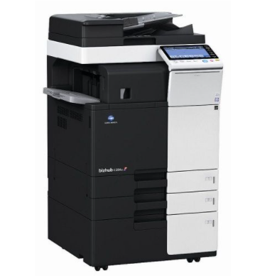
Konica-Minolta bizhub C284e
Рейтинг


Модули
Fusing Drive Section 2
BYPASS TRAY SECTION
OPERATION PANEL SECTION
EXTERNAL PARTS 2
ELECTRICAL COMPONENTS
2ND CASSETTE SECTION
ELECTRICAL COMPONENTS 2
PAPER EXIT SECTION 2
SCANNER SECTION
ERASE LAMP SECTION
IR COVER SECTION
WASTE TONER BOX SECTION
VERTICAL TRANSPORT SECTION 2
CASSETTE RAIL SECTION
Fusing Drive Section
INNER COVER SECTION
PAPER EXIT SECTION
PAPER SIZE DETECTION SECTION
High Voltage Section
1ST CASSETTE SECTION 2
TRANSFER UNIT
MAIN POWER SUPPLY SECTION
PAPER FEED SECTION
TONER SUPPLY SECTION
2ND CASSETTE SECTION 2
VERTICAL CONVEYANCE DOOR SECTION
TONER BOTTLE DRIVE SECTION
PH UNIT
1ST CASSETTE SECTION
TONER SUPPLY SECTION 2
REVERSAL UNIT
2ND PAPER FEED SECTION 2
MAIN DRIVE, PAPER FEED DRIVE SECTION
VERTICAL TRANSPORT SECTION
CONVEYANCE SECTION
2ND PAPER FEED SECTION
EXTERNAL PARTS
FUSING SECTION
OZONE DUCT SECTION
BYPASS TRAY SECTION 2
SCANNER SECTION 2
1ST PAPER FEED SECTION 2
DV LOCK LEVER SECTION
1ST PAPER FEED SECTION
SCANNER SECTION 3
Детали ERASE LAMP SECTION

| Деталь: | Stepping motor |
| Парткод: | A02EM10400 |
| Деталь: | brushless Motor /20 |
| Парткод: | A161M10200 |
| Деталь: | BUSHING |
| Парткод: | A161232300 |
| Деталь: | Caulking(Mounting Plate Fuser DriveL) |
| Парткод: | A161F25001 |
| Деталь: | SHAFT |
| Парткод: | A161231800 |
| Деталь: | CLUTCH |
| Парткод: | A161M20100 |
| Деталь: | GEAR 27T |
| Парткод: | A161230600 |
| Деталь: | Gear 24/70T |
| Парткод: | A161230500 |
| Деталь: | Gear 22/70T |
| Парткод: | A161228000 |
| Деталь: | Gear 33T |
| Парткод: | A161228100 |
| Деталь: | SHAFT |
| Парткод: | A161228312 |
| Деталь: | PIN B 3X12 |
| Парткод: | 56AA17471 |
| Деталь: | SHAFT |
| Парткод: | A161258700 |
| Деталь: | Gear 26/35T |
| Парткод: | A161259100 |
| Деталь: | Gear 35/45T |
| Парткод: | A161259200 |
| Деталь: | Slide Spacer |
| Парткод: | A1RF505400 |
| Деталь: | BUSHING |
| Парткод: | A161254700 |
| Деталь: | TORSION COIL SPRING |
| Парткод: | A161258501 |
| Деталь: | LEVER |
| Парткод: | A161228600 |
| Деталь: | CLUTCH |
| Парткод: | A161M20400 |
| Деталь: | Wiring Cover /A |
| Парткод: | A161592800 |
| Деталь: | PHOTOINTERRUPTER |
| Парткод: | A108M50100 |
| Деталь: | MOUNTING PLATE |
| Парткод: | A161591900 |
| Деталь: | Paperfeed Drive harness /1 |
| Парткод: | A161N12200 |
| Деталь: | Paper feed Frame |
| Парткод: | A161590201 |
| Деталь: | REINFORCE PLATE |
| Парткод: | A161594100 |
| Деталь: | Guide Sheet |
| Парткод: | A161594700 |
| Деталь: | Auxiliary Guide |
| Парткод: | A161591700 |
| Деталь: | BUSHING |
| Парткод: | A02E596300 |
| Деталь: | ROLLER |
| Парткод: | A00F623201 |
| Деталь: | Slide Stopper |
| Парткод: | A161594400 |
| Деталь: | Paper feed Shaft |
| Парткод: | A161591500 |
| Деталь: | Drive Shaft |
| Парткод: | A161591400 |
| Деталь: | Paper feed Cam |
| Парткод: | A161593300 |
| Деталь: | Caulking(Mounting Plate Drive Frame) |
| Парткод: | A161F59000 |
| Деталь: | GEAR 22T |
| Парткод: | A02E595400 |
| Деталь: | BUSHING |
| Парткод: | 4131353202 |
| Деталь: | Bypass Gear 24T |
| Парткод: | A161590800 |
| Деталь: | REINFORCE PLATE |
| Парткод: | A161590600 |
| Деталь: | GEAR 30T |
| Парткод: | A02E596100 |
| Деталь: | CLUTCH ASSY |
| Парткод: | A02E595100 |
| Деталь: | CLUTCH |
| Парткод: | A02EM20100 |
| Деталь: | COVER |
| Парткод: | A0ED597800 |
| Деталь: | SOLENOID |
| Парткод: | 9J06M20000 |
| Деталь: | Light blocking Plate |
| Парткод: | A161591300 |
| Деталь: | Drive Cover |
| Парткод: | A161591200 |
| Деталь: | Hold Claw |
| Парткод: | A161594800 |
| Деталь: | Coil spring |
| Парткод: | A161594900 |
| Деталь: | Multiple Bypass Tray Assy |
| Парткод: | A5C1R71100 |
| Деталь: | PANEL ASSEMBLY |
| Парткод: | A5C1M70203 |
| Деталь: | PANEL ASSEMBLY |
| Парткод: | A5C1M70103 |
| Деталь: | PANEL ASSEMBLY |
| Парткод: | A5C1M70003 |
| Деталь: | COVER |
| Парткод: | A161190900 |
| Деталь: | MOUNTING PLATE ASSY |
| Парткод: | A5C1R70911 |
| Деталь: | COVER |
| Парткод: | A161162604 |
| Деталь: | COVER |
| Парткод: | A161161503 |
| Деталь: | COVER |
| Парткод: | A161164000 |
| Деталь: | PWB assembly(PWB-UCN ASSY) |
| Парткод: | A0P0H02500 |
| Деталь: | MOUNTING PLATE |
| Парткод: | A161138002 |
| Деталь: | Light blocking Cover |
| Парткод: | A5C1167202 |
| Деталь: | Exposure Plate |
| Парткод: | A5C1167500 |
| Деталь: | FILM |
| Парткод: | A5C1167600 |
| Деталь: | LENS |
| Парткод: | A5C1167000 |
| Деталь: | Indicating Board |
| Парткод: | A5C1M30001 |
| Деталь: | Label Emperon |
| Парткод: | A011946200 |
| Деталь: | COVER |
| Парткод: | A5C1161701 |
| Деталь: | LENS |
| Парткод: | A161167100 |
| Деталь: | Light blocking Sheet |
| Парткод: | A5C1167400 |
| Деталь: | PWB Assembly(PWB-LEDCNT) |
| Парткод: | A5C1H00E01 |
| Деталь: | COVER |
| Парткод: | A161161900 |
| Деталь: | MOUNTING PLATE |
| Парткод: | A161164104 |
| Деталь: | CABLE |
| Парткод: | A0P0N15300 |
| Деталь: | MOUNTING PLATE |
| Парткод: | A5C1137302 |
| Деталь: | SPEAKER |
| Парткод: | A0P0M73100 |
| Деталь: | COVER |
| Парткод: | A161161401 |
| Деталь: | SEAL |
| Парткод: | A161162400 |
| Деталь: | INTERFACE CABLE |
| Парткод: | A5C1N15601 |
| Деталь: | COVER |
| Парткод: | A55V161201 |
| Деталь: | Indicating Wiring |
| Парткод: | A5C1N10800 |
| Деталь: | Indicating Wiring |
| Парткод: | A5C1N10700 |
| Деталь: | Light blocking Seal |
| Парткод: | A5C1167700 |
| Деталь: | SPACER |
| Парткод: | A5C1122600 |
| Деталь: | FERRITECORE |
| Парткод: | A5C1M92000 |
| Деталь: | Indicating Wiring/3 |
| Парткод: | A5C1N10B00 |
| Деталь: | Indicating Wiring/4 |
| Парткод: | A5C1N10C00 |
| Деталь: | FNS Relay harness |
| Парткод: | A5C1N10M00 |
| Деталь: | COVER |
| Парткод: | A161162102 |
| Деталь: | COVER |
| Парткод: | A161163501 |
| Деталь: | LABEL |
| Парткод: | A2X0945700 |
| Деталь: | LABEL |
| Парткод: | A2X0945000 |
| Деталь: | COVER |
| Парткод: | A161166302 |
| Деталь: | LABEL |
| Парткод: | A02E149900 |
| Деталь: | Label 220-240V 0.65A |
| Парткод: | A00J945201 |
| Деталь: | COVER |
| Парткод: | A5C1160601 |
| Деталь: | Regulating Part /Lower |
| Парткод: | A161164800 |
| Деталь: | Regulating Part /Middle |
| Парткод: | A161164702 |
| Деталь: | COVER |
| Парткод: | A5C1161800 |
| Деталь: | COVER |
| Парткод: | A161164401 |
| Деталь: | COVER |
| Парткод: | A5C1166501 |
| Деталь: | COVER |
| Парткод: | A161166400 |
| Деталь: | COVER |
| Парткод: | A5C1160901 |
| Деталь: | PULLING COIL SPRING |
| Парткод: | A161163900 |
| Деталь: | COVER |
| Парткод: | A161139800 |
| Деталь: | Regulating Part /Upper |
| Парткод: | A161164600 |
| Деталь: | GROUND PLATE |
| Парткод: | A5C1133700 |
| Деталь: | GUIDE |
| Парткод: | A5C1132000 |
| Деталь: | COVER |
| Парткод: | A161161201 |
| Деталь: | COVER |
| Парткод: | A161162900 |
| Деталь: | COVER |
| Парткод: | A161162201 |
| Деталь: | COVER |
| Парткод: | A161162801 |
| Деталь: | SHIELD PLATE |
| Парткод: | A5C1132300 |
| Деталь: | CUSHION |
| Парткод: | A161108000 |
| Деталь: | HOLDER |
| Парткод: | A161131400 |
| Деталь: | SPACER |
| Парткод: | A161136500 |
| Деталь: | HOLDER |
| Парткод: | A161137802 |
| Деталь: | Support Shaft |
| Парткод: | A161130801 |
| Деталь: | LABEL |
| Парткод: | 9J06730101 |
| Деталь: | MOUNTING PLATE |
| Парткод: | A161130502 |
| Деталь: | MOUNTING PLATE |
| Парткод: | A0ED135700 |
| Деталь: | Power code /120V |
| Парткод: | A1UDN30001 |
| Деталь: | Power source Cord /100V |
| Парткод: | A0EDN30002 |
| Деталь: | MOUNTING PLATE |
| Парткод: | A161130603 |
| Деталь: | AC Wiring /100V |
| Парткод: | A161N10002 |
| Деталь: | AC Wiring /120V |
| Парткод: | A161N10102 |
| Деталь: | AC Wiring/230V |
| Парткод: | A5C1N10200 |
| Деталь: | Power Supply Wiring |
| Парткод: | A02EN12513 |
| Деталь: | GROUND PLATE |
| Парткод: | A161622100 |
| Деталь: | SHEET |
| Парткод: | A161626200 |
| Деталь: | ROLL |
| Парткод: | A161623400 |
| Деталь: | Reinforce Plate /Right |
| Парткод: | A161633101 |
| Деталь: | Label FD |
| Парткод: | A00J942202 |
| Деталь: | LABEL |
| Парткод: | A161943500 |
| Деталь: | LABEL |
| Парткод: | A161943601 |
| Деталь: | LABEL |
| Парткод: | A161943802 |
| Деталь: | HOLDER |
| Парткод: | A161626300 |
| Деталь: | LEVER |
| Парткод: | A161636502 |
| Деталь: | LEVER |
| Парткод: | A161626601 |
| Деталь: | PULLING COIL SPRING |
| Парткод: | A161626800 |
| Деталь: | LENS |
| Парткод: | A161626000 |
| Деталь: | Light blocking Sheet |
| Парткод: | A161626100 |
| Деталь: | Label 2 |
| Парткод: | A161943200 |
| Деталь: | COVER |
| Парткод: | A161635012 |
| Деталь: | COVER |
| Парткод: | A161625900 |
| Деталь: | HANDLE |
| Парткод: | A161626900 |
| Деталь: | COVER |
| Парткод: | A161635115 |
| Деталь: | CUSHION |
| Парткод: | A5C1628100 |
| Деталь: | Reinforce Plate /Left |
| Парткод: | A161633202 |
| Деталь: | 2nd Cassette |
| Парткод: | A161F6301L |
| Деталь: | SHEET |
| Парткод: | A161134500 |
| Деталь: | Shield Case |
| Парткод: | A5C1131900 |
| Деталь: | SHOULDER SCREW |
| Парткод: | A161138601 |
| Деталь: | MOUNTING PLATE |
| Парткод: | A5C1137402 |
| Деталь: | Protection Seal |
| Парткод: | A161135700 |
| Деталь: | MOUNTING PLATE |
| Парткод: | A5C1138800 |
| Деталь: | COVER |
| Парткод: | A161137501 |
| Деталь: | PWB Assembly(PWB-MCL ASSY) |
| Парткод: | A5C1H00102 |
| Деталь: | FlatCable |
| Парткод: | A5C1N11800 |
| Деталь: | PWB Assembly(PWB-MFP) |
| Парткод: | A5C1H02007 |
| Деталь: | SHOULDER SCREW |
| Парткод: | A161139901 |
| Деталь: | BUSHING |
| Парткод: | A0P0144400 |
| Деталь: | SHOULDER SCREW |
| Парткод: | A5C1133800 |
| Деталь: | COMPRESSING COIL SPRING |
| Парткод: | A5C1133900 |
| Деталь: | SHOULDER SCREW |
| Парткод: | A0P0144300 |
| Деталь: | CABLE |
| Парткод: | A0P0N15100 |
| Деталь: | CABLE |
| Парткод: | A0P0N15200 |
| Деталь: | HDD |
| Парткод: | A2X0M72C00 |
| Деталь: | MOUNTING PLATE |
| Парткод: | A161130700 |
| Деталь: | SHOULDER SCREW |
| Парткод: | A161137600 |
| Деталь: | MEMORY MODULES |
| Парткод: | V865300026 |
| Деталь: | DUCT |
| Парткод: | A161140101 |
| Деталь: | FAN MOTOR |
| Парткод: | A0EDM10500 |
| Деталь: | Control Relay harness |
| Парткод: | A161N12602 |
| Деталь: | Controller Detection harness |
| Парткод: | A161N11B00 |
| Деталь: | PHOTOINTERRUPTER |
| Парткод: | A108M50100 |
| Деталь: | MOUNTING PLATE |
| Парткод: | A5C1139400 |
| Деталь: | MOUNTING PLATE |
| Парткод: | A5C1131600 |
| Деталь: | COVER |
| Парткод: | A161139501 |
| Деталь: | SHOULDER SCREW |
| Парткод: | A0P0742300 |
| Деталь: | COVER |
| Парткод: | A0ED131900 |
| Деталь: | SCREW |
| Парткод: | A161137900 |
| Деталь: | GASKET |
| Парткод: | A5C1M90000 |
| Деталь: | Shield Case |
| Парткод: | A5C1131801 |
| Деталь: | ROLL |
| Парткод: | 4004590301 |
| Деталь: | SPRING |
| Парткод: | A161892400 |
| Деталь: | SHAFT |
| Парткод: | 4025598401 |
| Деталь: | ROLLER |
| Парткод: | A161895400 |
| Деталь: | SHOULDER SCREW |
| Парткод: | 1164202801 |
| Деталь: | BUSHING |
| Парткод: | A0ED891100 |
| Деталь: | Ground Contact /Upper |
| Парткод: | A161895502 |
| Деталь: | Neutralizing Brush |
| Парткод: | A161894000 |
| Деталь: | Ground Contact /Lower |
| Парткод: | A161895600 |
| Деталь: | CUSHION |
| Парткод: | A161893600 |
| Деталь: | Guide Lever |
| Парткод: | A161890401 |
| Деталь: | ROLL |
| Парткод: | A0P0901100 |
| Деталь: | SPRING |
| Парткод: | A161892100 |
| Деталь: | Guide Part /Lower |
| Парткод: | A161890202 |
| Деталь: | COLLAR |
| Парткод: | A0ED897700 |
| Деталь: | PIN |
| Парткод: | 4036254901 |
| Деталь: | SEAL |
| Парткод: | A161893800 |
| Деталь: | BUSHING |
| Парткод: | A161891000 |
| Деталь: | MOUNTING PLATE |
| Парткод: | A161892300 |
| Деталь: | SPRING |
| Парткод: | A161892000 |
| Деталь: | SOLENOID ASSY |
| Парткод: | A161R72600 |
| Деталь: | Caulking(Mounting Plate) |
| Парткод: | A161F89001 |
| Деталь: | Paper exit Main body |
| Парткод: | A161890102 |
| Деталь: | GROUND SPRING |
| Парткод: | A161900100 |
| Деталь: | Pulley 18T |
| Парткод: | A161891301 |
| Деталь: | Fixing Part |
| Парткод: | A161892901 |
| Деталь: | ROLLER |
| Парткод: | A161890300 |
| Деталь: | Paper exit Guide /Lower |
| Парткод: | A161895201 |
| Деталь: | Paper exit Guide /Upper |
| Парткод: | A161895102 |
| Деталь: | Pulley 44T |
| Парткод: | A161895800 |
| Деталь: | GROUND SPRING |
| Парткод: | A161900201 |
| Деталь: | GROUND SPRING |
| Парткод: | A161900300 |
| Деталь: | Holding Plate |
| Парткод: | A161268300 |
| Деталь: | ORIGINAL GLASS ASSY |
| Парткод: | A161R72200 |
| Деталь: | Holding Plate |
| Парткод: | A161268200 |
| Деталь: | GUIDE |
| Парткод: | A161281600 |
| Деталь: | Scanner Wiring /1 |
| Парткод: | A161N14100 |
| Деталь: | TAPE |
| Парткод: | 4036307501 |
| Деталь: | REGULATING PLATE |
| Парткод: | A00J265300 |
| Деталь: | SEAL |
| Парткод: | 4581162501 |
| Деталь: | Lead Switch |
| Парткод: | A1UDM50200 |
| Деталь: | SEAL |
| Парткод: | A5C1263300 |
| Деталь: | SEAL |
| Парткод: | A161263000 |
| Деталь: | Scanner Wiring /2 |
| Парткод: | A161N14200 |
| Деталь: | PHOTOINTERRUPTER |
| Парткод: | A108M50100 |
| Деталь: | COVER |
| Парткод: | A161262200 |
| Деталь: | FRAME |
| Парткод: | A161261902 |
| Деталь: | FRAME |
| Парткод: | A161262002 |
| Деталь: | COMPRESSING COIL SPRING |
| Парткод: | A161280300 |
| Деталь: | MOUNTING PLATE |
| Парткод: | A161280112 |
| Деталь: | Slit Glass Assy |
| Парткод: | A161R72300 |
| Деталь: | LEVER |
| Парткод: | A161280211 |
| Деталь: | PWB Assembly(PWB-ID) |
| Парткод: | A5C1H01A00 |
| Деталь: | SEAL |
| Парткод: | A161281300 |
| Деталь: | APS Photoreflector |
| Парткод: | A161M50A00 |
| Деталь: | GUIDE |
| Парткод: | A161281100 |
| Деталь: | SEAL |
| Парткод: | A5C1263400 |
| Деталь: | Light blocking Part |
| Парткод: | A0ED105500 |
| Деталь: | SEAL |
| Парткод: | A161107300 |
| Деталь: | HOLDER |
| Парткод: | A161130101 |
| Деталь: | RAIL |
| Парткод: | A0ED105400 |
| Деталь: | SEAL |
| Парткод: | A161102800 |
| Деталь: | RAIL |
| Парткод: | A161105600 |
| Деталь: | PIN |
| Парткод: | A0ED103100 |
| Деталь: | SEAL |
| Парткод: | A161107200 |
| Деталь: | SEAL |
| Парткод: | A161107100 |
| Деталь: | GUIDE |
| Парткод: | A161138500 |
| Деталь: | Eraser (YMC) Assy |
| Парткод: | A161R70100 |
| Деталь: | Eraser (Black) Assy |
| Парткод: | A161R70011 |
| Деталь: | Light blocking Part |
| Парткод: | A161107400 |
| Деталь: | Read Cover /Rear |
| Парткод: | A161170203 |
| Деталь: | LABEL |
| Парткод: | A161940602 |
| Деталь: | Read Cover |
| Парткод: | A161170701 |
| Деталь: | Read Cover |
| Парткод: | A161170601 |
| Деталь: | SHOULDER SCREW |
| Парткод: | A00J169300 |
| Деталь: | Read Cover /Right |
| Парткод: | A161170400 |
| Деталь: | COVER |
| Парткод: | A02E167700 |
| Деталь: | HOLDER |
| Парткод: | A161170800 |
| Деталь: | Read Cover /Front |
| Парткод: | A161170100 |
| Деталь: | LABEL |
| Парткод: | A3EW944600 |
| Деталь: | Label Prohibit |
| Парткод: | A121944700 |
| Деталь: | Ground Sheet |
| Парткод: | A161282100 |
| Деталь: | Read Cover /Left |
| Парткод: | A161170300 |
| Деталь: | Scanner Relay harness /100V |
| Парткод: | A161N11C01 |
| Деталь: | LABEL |
| Парткод: | A1UD947400 |
| Деталь: | SHUTTER |
| Парткод: | A0ED363100 |
| Деталь: | PULLING COIL SPRING |
| Парткод: | A0ED363200 |
| Деталь: | SEAL |
| Парткод: | A0ED363400 |
| Деталь: | PIPE |
| Парткод: | A0ED363000 |
| Деталь: | SEAL |
| Парткод: | A0ED363300 |
| Деталь: | Gear 16/40T |
| Парткод: | A161245100 |
| Деталь: | Gear 20/20T |
| Парткод: | A0ED245000 |
| Деталь: | Gear 16/51T |
| Парткод: | A161245400 |
| Деталь: | Waste Toner Box |
| Парткод: | A4NNWY1 |
| Деталь: | Waste Toner Driva |
| Парткод: | A161F21000 |
| Деталь: | Waste Toner Pipe |
| Парткод: | A0EDF36000 |
| Деталь: | COVER |
| Парткод: | A161362000 |
| Деталь: | Pulley 22T |
| Парткод: | A0ED811700 |
| Деталь: | Drive Belt 266L |
| Парткод: | A161719000 |
| Деталь: | Gear 22/23T |
| Парткод: | A161709100 |
| Деталь: | COLLAR |
| Парткод: | A0ED811900 |
| Деталь: | Pressing Spring |
| Парткод: | A161711200 |
| Деталь: | Cover /C |
| Парткод: | A161712600 |
| Деталь: | Bushing /1 |
| Парткод: | A161713100 |
| Деталь: | Roller /A |
| Парткод: | A161710500 |
| Деталь: | Idler Roller /A |
| Парткод: | A161825700 |
| Деталь: | BUSHING |
| Парткод: | A02E815200 |
| Деталь: | Label M6 |
| Парткод: | A161946400 |
| Деталь: | Guide Plate /A |
| Парткод: | A161710202 |
| Деталь: | Lock Shaft /A |
| Парткод: | A161711300 |
| Деталь: | Spring /B |
| Парткод: | A161711700 |
| Деталь: | Label M1 |
| Парткод: | A161946200 |
| Деталь: | Lock Shaft |
| Парткод: | A5C1711500 |
| Деталь: | Open/close Lever |
| Парткод: | A161711600 |
| Деталь: | Fixing Part |
| Парткод: | A161714500 |
| Деталь: | Ground Plate /D |
| Парткод: | A161712000 |
| Деталь: | ACTUATOR |
| Парткод: | A161713500 |
| Деталь: | Spring /D |
| Парткод: | A161712800 |
| Деталь: | Conveyance Spring /B |
| Парткод: | A161714600 |
| Деталь: | Ground Plate /E |
| Парткод: | A161712100 |
| Деталь: | MOUNTING PLATE |
| Парткод: | A161710401 |
| Деталь: | SCREW |
| Парткод: | 4163529301 |
| Деталь: | Lock plate |
| Парткод: | A161816300 |
| Деталь: | PHOTOINTERRUPTER |
| Парткод: | A108M50100 |
| Деталь: | PLATE SPRING |
| Парткод: | A0ED702400 |
| Деталь: | Guide Plate /B |
| Парткод: | A161710300 |
| Деталь: | Gear 23T |
| Парткод: | A161719100 |
| Деталь: | Support Plate /Rear |
| Парткод: | A161711900 |
| Деталь: | Ground Spring /D |
| Парткод: | A161712900 |
| Деталь: | TORSION COIL SPRING |
| Парткод: | A161104300 |
| Деталь: | STOPPER |
| Парткод: | A161102300 |
| Деталь: | SHAFT |
| Парткод: | A161104200 |
| Деталь: | LEVER |
| Парткод: | A161101900 |
| Деталь: | REINFORCE PLATE |
| Парткод: | A161104701 |
| Деталь: | MOUNTING PLATE |
| Парткод: | A161104800 |
| Деталь: | RUBBER FOOT |
| Парткод: | 996305501 |
| Деталь: | RAIL |
| Парткод: | A161101101 |
| Деталь: | SHAFT |
| Парткод: | A161105800 |
| Деталь: | ROLL |
| Парткод: | A161103901 |
| Деталь: | MOUNTING PLATE |
| Парткод: | A161104400 |
| Деталь: | COVER |
| Парткод: | A161103700 |
| Деталь: | ROLL |
| Парткод: | A161623400 |
| Деталь: | SHAFT |
| Парткод: | A161105200 |
| Деталь: | MOUNTING PLATE |
| Парткод: | A161101600 |
| Деталь: | MOUNTING PLATE |
| Парткод: | A161101700 |
| Деталь: | HOLDER |
| Парткод: | A161104002 |
| Деталь: | Gear 18/115T |
| Парткод: | A161254200 |
| Деталь: | Gear 18/57T |
| Парткод: | A161254300 |
| Деталь: | Gear 33/55T |
| Парткод: | A161254400 |
| Деталь: | BUSHING |
| Парткод: | A161254700 |
| Деталь: | GEAR 38T |
| Парткод: | A161254500 |
| Деталь: | BUSHING |
| Парткод: | A161232200 |
| Деталь: | Gear 22/23T |
| Парткод: | A161228800 |
| Деталь: | BUSHING |
| Парткод: | A161702200 |
| Деталь: | SHAFT |
| Парткод: | A161256300 |
| Деталь: | Caulking(Mounting Plate Fuser Drive2L) |
| Парткод: | A161F25102 |
| Деталь: | BUSHING |
| Парткод: | A0ED259700 |
| Деталь: | SHAFT |
| Парткод: | A161259400 |
| Деталь: | MOUNTING PLATE |
| Парткод: | A161258800 |
| Деталь: | GEAR 26T |
| Парткод: | A0ED257500 |
| Деталь: | GEAR 16T |
| Парткод: | 4038258001 |
| Деталь: | TORSION COIL SPRING |
| Парткод: | A161232501 |
| Деталь: | BUSHING |
| Парткод: | A161232300 |
| Деталь: | Gear 18/18T |
| Парткод: | A5C1231300 |
| Деталь: | GEAR 18T |
| Парткод: | A161230700 |
| Деталь: | COLLAR |
| Парткод: | A2XK224100 |
| Деталь: | COLLAR |
| Парткод: | A161232401 |
| Деталь: | GEAR 12T |
| Парткод: | A161122002 |
| Деталь: | Caulking |
| Парткод: | A161F10901 |
| Деталь: | GEAR 17T |
| Парткод: | A161121900 |
| Деталь: | Label M4 |
| Парткод: | A161941100 |
| Деталь: | GEAR 16T |
| Парткод: | A161228700 |
| Деталь: | GEAR |
| Парткод: | A161254600 |
| Деталь: | Fusing Drive Assy |
| Парткод: | A5C1R71211 |
| Деталь: | Fixing Claw |
| Парткод: | A161165700 |
| Деталь: | Cover Front(2nd) |
| Парткод: | A161F16102 |
| Деталь: | LABEL |
| Парткод: | A161943000 |
| Деталь: | Cover /Front |
| Парткод: | A161165006 |
| Деталь: | PROTECTION PART |
| Парткод: | A161165300 |
| Деталь: | BAND |
| Парткод: | A0ED162401 |
| Деталь: | Label DR/K |
| Парткод: | A161942500 |
| Деталь: | Label DR/C |
| Парткод: | A161942400 |
| Деталь: | LABEL |
| Парткод: | A161942600 |
| Деталь: | Label DR/M |
| Парткод: | A161942300 |
| Деталь: | Label DR/Y |
| Парткод: | A161942200 |
| Деталь: | LABEL |
| Парткод: | A161942101 |
| Деталь: | LABEL |
| Парткод: | A161942000 |
| Деталь: | SEESAW-SWITCH |
| Парткод: | 4038M60000 |
| Деталь: | MOUNTING PLATE |
| Парткод: | A161135100 |
| Деталь: | AC Wiring /A |
| Парткод: | A161N12A00 |
| Деталь: | MICRO SWITCH |
| Парткод: | 9J06M60100 |
| Деталь: | SHOULDER SCREW |
| Парткод: | 4038228702 |
| Деталь: | TORSION COIL SPRING |
| Парткод: | A161151300 |
| Деталь: | MOUNTING PLATE |
| Парткод: | A161151100 |
| Деталь: | Stepping motor |
| Парткод: | A0EDM10300 |
| Деталь: | Timing belt 231L |
| Парткод: | A161891401 |
| Деталь: | BELT |
| Парткод: | 4640392001 |
| Деталь: | Paper exit Cover |
| Парткод: | A161895300 |
| Деталь: | COVER |
| Парткод: | A161162302 |
| Деталь: | SHEET |
| Парткод: | A161894100 |
| Деталь: | Neutralizing Brush |
| Парткод: | A161894000 |
| Деталь: | SHOULDER SCREW |
| Парткод: | A0P0742300 |
| Деталь: | GUIDE PART |
| Парткод: | A161897200 |
| Деталь: | Paperfeed Wiring /Rear |
| Парткод: | A161N10N01 |
| Деталь: | SHOULDER SCREW |
| Парткод: | A161627801 |
| Деталь: | HOLDER |
| Парткод: | A161627500 |
| Деталь: | HOLDER |
| Парткод: | A161628011 |
| Деталь: | PHOTOINTERRUPTER |
| Парткод: | A161M50600 |
| Деталь: | PHOTOINTERRUPTER |
| Парткод: | A161M50501 |
| Деталь: | PRESSURE SPRING |
| Парткод: | 4002311002 |
| Деталь: | MOTOR |
| Парткод: | 9J06M10300 |
| Деталь: | HOLDER |
| Парткод: | A161627102 |
| Деталь: | HOLDER |
| Парткод: | A161627300 |
| Деталь: | COMPRESSING COIL SPRING |
| Парткод: | A0ED627600 |
| Деталь: | SHOULDER SCREW |
| Парткод: | A161627701 |
| Деталь: | PHOTOINTERRUPTER |
| Парткод: | A108M50100 |
| Деталь: | MOUNTING PLATE |
| Парткод: | A161132504 |
| Деталь: | PWB Assembly(PWB-DC Assy) |
| Парткод: | A161H00C02 |
| Деталь: | REINFORCE PLATE |
| Парткод: | A161132800 |
| Деталь: | GUIDE |
| Парткод: | A161132101 |
| Деталь: | HOLDER |
| Парткод: | A161137701 |
| Деталь: | HV Contact Assy |
| Парткод: | A161R70211 |
| Деталь: | THERMISTOR |
| Парткод: | A0P0M50300 |
| Деталь: | GUIDE |
| Парткод: | A5C1134800 |
| Деталь: | Charging Wiring /K |
| Парткод: | A161N12P01 |
| Деталь: | Charging Wiring /C |
| Парткод: | A161N12N01 |
| Деталь: | Charging Wiring /M |
| Парткод: | A161N12M01 |
| Деталь: | Charging Wiring /Y |
| Парткод: | A161N12K01 |
| Деталь: | DV Contact Assy |
| Парткод: | A161R70322 |
| Деталь: | Transfer Wiring /2 |
| Парткод: | A161N11300 |
| Деталь: | Neutralizing Wiring |
| Парткод: | A161N11K00 |
| Деталь: | HIGH VOLTAGE UNIT |
| Парткод: | A5C1M40600 |
| Деталь: | Regulating Plate /Rear |
| Парткод: | A161620903 |
| Деталь: | LABEL MAX LEVEL |
| Парткод: | A161943700 |
| Деталь: | CUSHION |
| Парткод: | A161624100 |
| Деталь: | Lifting Shaft |
| Парткод: | A161621600 |
| Деталь: | RACK |
| Парткод: | A161621100 |
| Деталь: | SHOULDER SCREW |
| Парткод: | A161620600 |
| Деталь: | GEAR |
| Парткод: | A161620701 |
| Деталь: | LABEL |
| Парткод: | A161943000 |
| Деталь: | FRICTION SHEET |
| Парткод: | 4030322601 |
| Деталь: | LIFTING PLATE |
| Парткод: | A161620400 |
| Деталь: | KNOB |
| Парткод: | 4037320401 |
| Деталь: | PULLING COIL SPRING |
| Парткод: | A0ED621400 |
| Деталь: | LEVER |
| Парткод: | A161621300 |
| Деталь: | Regulating Plate /Front |
| Парткод: | A161620802 |
| Деталь: | LEVER |
| Парткод: | 4030320601 |
| Деталь: | GUIDE |
| Парткод: | A0ED620200 |
| Деталь: | MOUNTING PLATE |
| Парткод: | A161621900 |
| Деталь: | LEVER |
| Парткод: | A161621411 |
| Деталь: | Paper feed Cassette |
| Парткод: | A161620103 |
| Деталь: | PLATE SPRING |
| Парткод: | A161621800 |
| Деталь: | REGULATING PLATE |
| Парткод: | A161621701 |
| Деталь: | ACTUATOR |
| Парткод: | A0ED620701 |
| Деталь: | SCREW |
| Парткод: | 4163529301 |
| Деталь: | LABEL |
| Парткод: | A02E940300 |
| Деталь: | Intermediate Image Transfer Kit |
| Парткод: | A161R71300 |
| Деталь: | GUIDE |
| Парткод: | A161508400 |
| Деталь: | Lock Part |
| Парткод: | A161110601 |
| Деталь: | COMPRESSING COIL SPRING |
| Парткод: | A0ED111000 |
| Деталь: | Lever /Front |
| Парткод: | A161112500 |
| Деталь: | Arm /Front |
| Парткод: | A161112800 |
| Деталь: | Fusing Rail /Front |
| Парткод: | A161110400 |
| Деталь: | MOUNTING PLATE |
| Парткод: | A161112200 |
| Деталь: | Adjusting Plate |
| Парткод: | A161112600 |
| Деталь: | RAIL |
| Парткод: | A161110201 |
| Деталь: | RAIL |
| Парткод: | A161110300 |
| Деталь: | Contact /Color |
| Парткод: | A0ED111500 |
| Деталь: | CONTACT |
| Парткод: | A161112000 |
| Деталь: | CONTACT |
| Парткод: | A0ED112000 |
| Деталь: | DETECTING PLATE |
| Парткод: | A161110500 |
| Деталь: | PULLING COIL SPRING |
| Парткод: | A0ED110900 |
| Деталь: | CONTACT |
| Парткод: | A0ED111700 |
| Деталь: | Torsion Coil spring /R |
| Парткод: | A0ED111200 |
| Деталь: | Arm /Rear |
| Парткод: | A161112900 |
| Деталь: | CONTACT |
| Парткод: | A161112300 |
| Деталь: | PHOTOINTERRUPTER |
| Парткод: | A108M50100 |
| Деталь: | MOUNTING PLATE |
| Парткод: | A5C1112100 |
| Деталь: | Connecting Detection harness |
| Парткод: | A161N10J00 |
| Деталь: | Transfer Wiring /1 |
| Парткод: | A161N11200 |
| Деталь: | MOUNTING PLATE |
| Парткод: | A161112700 |
| Деталь: | CONTACT |
| Парткод: | A161112400 |
| Деталь: | Lever /Rear |
| Парткод: | A161112100 |
| Деталь: | RAIL |
| Парткод: | A161110102 |
| Деталь: | Contact /K |
| Парткод: | A0ED111400 |
| Деталь: | Torsion Coil spring /F |
| Парткод: | A0ED111100 |
| Деталь: | SEAL |
| Парткод: | A161144900 |
| Деталь: | DUCT |
| Парткод: | A161141700 |
| Деталь: | SEAL |
| Парткод: | A161146200 |
| Деталь: | SEAL |
| Парткод: | A161144801 |
| Деталь: | SCREW |
| Парткод: | 4163529301 |
| Деталь: | FILTER |
| Парткод: | A161145000 |
| Деталь: | Seal /3 |
| Парткод: | A161144500 |
| Деталь: | Seal /3 |
| Парткод: | A161143601 |
| Деталь: | Power supply Assy /100V |
| Парткод: | A5C1R70500 |
| Деталь: | Power supply Assy /230V |
| Парткод: | A5C1R70600 |
| Деталь: | SHEET |
| Парткод: | A5C1130200 |
| Деталь: | LABEL |
| Парткод: | A0CR953400 |
| Деталь: | Cooling Duct |
| Парткод: | A161140800 |
| Деталь: | CONNECTOR |
| Парткод: | V651010002 |
| Деталь: | FAN MOTOR |
| Парткод: | 4139M10000 |
| Деталь: | Seal /1 |
| Парткод: | A161143400 |
| Деталь: | COVER |
| Парткод: | A161100602 |
| Деталь: | HOLDER |
| Парткод: | A161561100 |
| Деталь: | PULLING COIL SPRING |
| Парткод: | A161561200 |
| Деталь: | COVER |
| Парткод: | A161579011 |
| Деталь: | Gear 27/33T |
| Парткод: | A161576300 |
| Деталь: | GEAR 36T |
| Парткод: | A161576200 |
| Деталь: | Caulking(Hold Plate Drive) |
| Парткод: | A161F56101 |
| Деталь: | Gear 21/26T |
| Парткод: | A161576100 |
| Деталь: | MOUNTING PLATE |
| Парткод: | A161565102 |
| Деталь: | PAPER FEED ASSY |
| Парткод: | A5C1R70700 |
| Деталь: | REINFORCE PLATE |
| Парткод: | A161120701 |
| Деталь: | SEAL |
| Парткод: | A161403701 |
| Деталь: | COVER |
| Парткод: | A161405213 |
| Деталь: | COVER |
| Парткод: | A161405113 |
| Деталь: | COVER |
| Парткод: | A161402013 |
| Деталь: | COVER |
| Парткод: | A161405311 |
| Деталь: | SUCTION PLATE |
| Парткод: | 4038101401 |
| Деталь: | SPACER |
| Парткод: | A161403901 |
| Деталь: | Label Toner 1 |
| Парткод: | A0ED940600 |
| Деталь: | SEAL |
| Парткод: | A161402501 |
| Деталь: | SHUTTER |
| Парткод: | A161402401 |
| Деталь: | SEAL |
| Парткод: | A161403800 |
| Деталь: | SEAL |
| Парткод: | A161403500 |
| Деталь: | SEAL |
| Парткод: | A161403600 |
| Деталь: | SEAL |
| Парткод: | A161403300 |
| Деталь: | SEAL |
| Парткод: | A161403400 |
| Деталь: | COVER |
| Парткод: | A161402112 |
| Деталь: | MOUNTING PLATE |
| Парткод: | A161135502 |
| Деталь: | Seal /1 |
| Парткод: | A161404001 |
| Деталь: | Seal /2 |
| Парткод: | A161404100 |
| Деталь: | Sub Hopper Assy |
| Парткод: | A161R71000 |
| Деталь: | Sub Hopper Assy |
| Парткод: | A161R71100 |
| Деталь: | Sub Hopper Assy |
| Парткод: | A161R71200 |
| Деталь: | Sub Hopper Assy |
| Парткод: | A161R72900 |
| Деталь: | Regulating Plate /Rear |
| Парткод: | A161620903 |
| Деталь: | LABEL MAX LEVEL |
| Парткод: | A161943700 |
| Деталь: | CUSHION |
| Парткод: | A161624100 |
| Деталь: | Lifting Shaft |
| Парткод: | A161621600 |
| Деталь: | RACK |
| Парткод: | A161621100 |
| Деталь: | SHOULDER SCREW |
| Парткод: | A161620600 |
| Деталь: | LABEL |
| Парткод: | A161943000 |
| Деталь: | GEAR |
| Парткод: | A161620701 |
| Деталь: | FRICTION SHEET |
| Парткод: | 4030322601 |
| Деталь: | LIFTING PLATE |
| Парткод: | A161620400 |
| Деталь: | KNOB |
| Парткод: | 4037320401 |
| Деталь: | PULLING COIL SPRING |
| Парткод: | A0ED621400 |
| Деталь: | SCREW |
| Парткод: | 4163529301 |
| Деталь: | LEVER |
| Парткод: | A161621300 |
| Деталь: | Regulating Plate /Front |
| Парткод: | A161620802 |
| Деталь: | LEVER |
| Парткод: | 4030320601 |
| Деталь: | GUIDE |
| Парткод: | A0ED620200 |
| Деталь: | MOUNTING PLATE |
| Парткод: | A161621900 |
| Деталь: | LEVER |
| Парткод: | A161631411 |
| Деталь: | PLATE SPRING |
| Парткод: | A161621800 |
| Деталь: | REGULATING PLATE |
| Парткод: | A161621701 |
| Деталь: | ACTUATOR |
| Парткод: | A0ED620701 |
| Деталь: | Paper feed Cassette |
| Парткод: | A161630102 |
| Деталь: | LABEL |
| Парткод: | A02E940300 |
| Деталь: | Adjusting Plate |
| Парткод: | A161121300 |
| Деталь: | Adjusting Plate |
| Парткод: | A161102500 |
| Деталь: | MICRO SWITCH |
| Парткод: | 9J06M60100 |
| Деталь: | SHOULDER SCREW |
| Парткод: | A161137100 |
| Деталь: | TORSION COIL SPRING |
| Парткод: | A161151200 |
| Деталь: | HOLDER |
| Парткод: | A161121200 |
| Деталь: | Wiring Cover /B |
| Парткод: | A161592900 |
| Деталь: | LOCK CLAW |
| Парткод: | A0ED712100 |
| Деталь: | Support Part /Upper |
| Парткод: | A161811500 |
| Деталь: | Lock plate |
| Парткод: | A161811001 |
| Деталь: | Lock Part /Middle |
| Парткод: | A161811401 |
| Деталь: | Open/close Handle |
| Парткод: | A161811100 |
| Деталь: | Lock /Middle |
| Парткод: | A161815201 |
| Деталь: | Lock Part /Lower |
| Парткод: | A161811302 |
| Деталь: | Pulling Spring |
| Парткод: | A161815500 |
| Деталь: | SHAFT |
| Парткод: | A161815300 |
| Деталь: | TORSION COIL SPRING |
| Парткод: | A161815900 |
| Деталь: | Lock Claw /Lower |
| Парткод: | A5C1811600 |
| Деталь: | ROLL |
| Парткод: | A161815400 |
| Деталь: | Guide Plate /2 |
| Парткод: | A161810301 |
| Деталь: | Paper feed Guide |
| Парткод: | A5C1590500 |
| Деталь: | GUIDE |
| Парткод: | A161241600 |
| Деталь: | Stepping motor |
| Парткод: | A02EM10400 |
| Деталь: | Stepping motor |
| Парткод: | A161M10300 |
| Деталь: | Drive Holder |
| Парткод: | A161240100 |
| Деталь: | Gear 18/91T |
| Парткод: | A161240300 |
| Деталь: | Gear 65T |
| Парткод: | A161240600 |
| Деталь: | GEAR 29T |
| Парткод: | A161240500 |
| Деталь: | Gear 29/62T |
| Парткод: | A161240400 |
| Деталь: | PRESSURE SPRING |
| Парткод: | 4038541202 |
| Деталь: | JOINT |
| Парткод: | A161240700 |
| Деталь: | Gear 20/42T |
| Парткод: | A161240900 |
| Деталь: | MOUNTING PLATE |
| Парткод: | A161241500 |
| Деталь: | Gear 31T |
| Парткод: | A161241000 |
| Деталь: | SHAFT |
| Парткод: | A161241200 |
| Деталь: | GEAR 17T |
| Парткод: | A161241400 |
| Деталь: | Toner bottle Drive Assy |
| Парткод: | A161R70811 |
| Деталь: | DUCT |
| Парткод: | A161140200 |
| Деталь: | FAN MOTOR |
| Парткод: | 4139M10000 |
| Деталь: | SCREW |
| Парткод: | 4163529301 |
| Деталь: | GUIDE |
| Парткод: | A161135300 |
| Деталь: | POSITIONING PLATE |
| Парткод: | A161105400 |
| Деталь: | PWB Assembly(PWB-FR) |
| Парткод: | A5C1H00500 |
| Деталь: | MOUNTING PLATE |
| Парткод: | A161101802 |
| Деталь: | MOUNTING PLATE |
| Парткод: | A161130301 |
| Деталь: | PWB Assembly(PWB-VD2 ASSY) |
| Парткод: | A161H00800 |
| Деталь: | HOLDER |
| Парткод: | A161137802 |
| Деталь: | Flatcable/25 |
| Парткод: | A5C1N11900 |
| Деталь: | PRINT HEAD ASSY |
| Парткод: | A161R70911 |
| Деталь: | DUCT |
| Парткод: | A161147401 |
| Деталь: | GROUND PLATE |
| Парткод: | A161622100 |
| Деталь: | SHEET |
| Парткод: | A161626200 |
| Деталь: | ROLL |
| Парткод: | A161623400 |
| Деталь: | Reinforce Plate /Right |
| Парткод: | A161623101 |
| Деталь: | Label FD |
| Парткод: | A00J942202 |
| Деталь: | Label Cd |
| Парткод: | A02E941500 |
| Деталь: | LABEL |
| Парткод: | A161943802 |
| Деталь: | HOLDER |
| Парткод: | A161626300 |
| Деталь: | LEVER |
| Парткод: | A161626502 |
| Деталь: | LEVER |
| Парткод: | A161626601 |
| Деталь: | PULLING COIL SPRING |
| Парткод: | A161626800 |
| Деталь: | LENS |
| Парткод: | A161626000 |
| Деталь: | Light blocking Sheet |
| Парткод: | A161626100 |
| Деталь: | Label 1 |
| Парткод: | A161943100 |
| Деталь: | COVER |
| Парткод: | A161625012 |
| Деталь: | COVER |
| Парткод: | A161625900 |
| Деталь: | HANDLE |
| Парткод: | A161626900 |
| Деталь: | COVER |
| Парткод: | A161625114 |
| Деталь: | CUSHION |
| Парткод: | A5C1628100 |
| Деталь: | Label FD |
| Парткод: | A02E941300 |
| Деталь: | Reinforce Plate /Left |
| Парткод: | A161623301 |
| Деталь: | 1st Cassette |
| Парткод: | A161F6201K |
| Деталь: | Gear 43T |
| Парткод: | A161401400 |
| Деталь: | Gear 17/65T |
| Парткод: | A161401300 |
| Деталь: | GEAR 25T |
| Парткод: | A161401500 |
| Деталь: | GEAR 28T |
| Парткод: | A161401200 |
| Деталь: | GEAR 36T |
| Парткод: | A161401100 |
| Деталь: | GEAR 18T |
| Парткод: | A161401000 |
| Деталь: | BUSHING |
| Парткод: | 4163510201 |
| Деталь: | SEAL |
| Парткод: | 4576536301 |
| Деталь: | HOLDER |
| Парткод: | A161403100 |
| Деталь: | SCREW |
| Парткод: | A161400100 |
| Деталь: | DETECTING PLATE |
| Парткод: | A161400401 |
| Деталь: | Detecting Seal |
| Парткод: | A161400601 |
| Деталь: | Agitating Part |
| Парткод: | A161400300 |
| Деталь: | Agitating Shaft |
| Парткод: | A161400200 |
| Деталь: | Toner Drive harness /K |
| Парткод: | A161N12801 |
| Деталь: | Stepping motor |
| Парткод: | A02EM10400 |
| Деталь: | SEAL |
| Парткод: | 4333501201 |
| Деталь: | BUSHING |
| Парткод: | A161403000 |
| Деталь: | Detecting Actuator |
| Парткод: | A161404300 |
| Деталь: | MOUNTING PLATE |
| Парткод: | A161400701 |
| Деталь: | Toner Detection harness /1 |
| Парткод: | A161N10F01 |
| Деталь: | PHOTOINTERRUPTER |
| Парткод: | A108M50100 |
| Деталь: | SEAL |
| Парткод: | A161403200 |
| Деталь: | TENSION SPRING |
| Парткод: | 4036534801 |
| Деталь: | SHUTTER |
| Парткод: | A0ED401000 |
| Деталь: | PIN |
| Парткод: | A161400800 |
| Деталь: | SEAL |
| Парткод: | A161146800 |
| Деталь: | Fixing Plate |
| Парткод: | A161404200 |
| Деталь: | Cover /Upper |
| Парткод: | A161810701 |
| Деталь: | Guide Door /Right |
| Парткод: | A161810102 |
| Деталь: | Cover Door |
| Парткод: | A161815100 |
| Деталь: | GUIDE PLATE |
| Парткод: | A5C1812200 |
| Деталь: | Roller /C |
| Парткод: | A161814601 |
| Деталь: | Roller /B |
| Парткод: | A161813701 |
| Деталь: | BUSHING |
| Парткод: | A02E815200 |
| Деталь: | Label M5 |
| Парткод: | A161946100 |
| Деталь: | Knob /A |
| Парткод: | A161814700 |
| Деталь: | Swing Holder |
| Парткод: | A161815600 |
| Деталь: | Open/close Claw |
| Парткод: | A161815700 |
| Деталь: | Swing Spring |
| Парткод: | A161815800 |
| Деталь: | Guide Plate /1 |
| Парткод: | A161810200 |
| Деталь: | Bushing /A |
| Парткод: | A161813300 |
| Деталь: | Collar /A |
| Парткод: | A161813800 |
| Деталь: | Gear 22/29T |
| Парткод: | A5C1819700 |
| Деталь: | Spacer /A |
| Парткод: | A161816400 |
| Деталь: | Pulley 22T |
| Парткод: | A0ED811700 |
| Деталь: | Drive Belt 156L |
| Парткод: | A161819000 |
| Деталь: | Stepping motor |
| Парткод: | A0EDM10200 |
| Деталь: | Caulking(Panel Rear) |
| Парткод: | A161F81102 |
| Деталь: | Gear 16/26T |
| Парткод: | A5C1819600 |
| Деталь: | Contact /B |
| Парткод: | A161814300 |
| Деталь: | Cover /B |
| Парткод: | A161814901 |
| Деталь: | GUIDE PLATE |
| Парткод: | A5C1810400 |
| Деталь: | Mounting Plate /3 |
| Парткод: | A161814401 |
| Деталь: | SCREW |
| Парткод: | 4163529301 |
| Деталь: | Conveyance Drive harness /Upper |
| Парткод: | A161N12100 |
| Деталь: | Mounting Plate /2 |
| Парткод: | A161810801 |
| Деталь: | Roller /1 |
| Парткод: | A161810600 |
| Деталь: | Cushion /A |
| Парткод: | A161825300 |
| Деталь: | Pressing Spring /A |
| Парткод: | A161813600 |
| Деталь: | Holding Part |
| Парткод: | A0ED815100 |
| Деталь: | Idler Roller /A |
| Парткод: | A161825700 |
| Деталь: | Cushion /B |
| Парткод: | A161825800 |
| Деталь: | PHOTOINTERRUPTER |
| Парткод: | A108M50100 |
| Деталь: | Bushing /C |
| Парткод: | A161819500 |
| Деталь: | Mounting Plate /4 |
| Парткод: | A161825100 |
| Деталь: | Contact /C |
| Парткод: | A161819400 |
| Деталь: | Bushing /B |
| Парткод: | A161814500 |
| Деталь: | ACTUATOR |
| Парткод: | A161813200 |
| Деталь: | Wiring Part |
| Парткод: | A161825400 |
| Деталь: | Contact /A |
| Парткод: | A161814202 |
| Деталь: | TORSION COIL SPRING |
| Парткод: | A161813400 |
| Деталь: | Cover /A |
| Парткод: | A161813902 |
| Деталь: | Wiring Part /2 |
| Парткод: | A161825600 |
| Деталь: | Mounting Plate /1 |
| Парткод: | A161810900 |
| Деталь: | Spring /D |
| Парткод: | A161712800 |
| Деталь: | ACTUATOR |
| Парткод: | A161813001 |
| Деталь: | TORSION COIL SPRING |
| Парткод: | A161813100 |
| Деталь: | Guide Plate /4 |
| Парткод: | A161810503 |
| Деталь: | Cover /D |
| Парткод: | A161825500 |
| Деталь: | BALL BEARING |
| Парткод: | A0TK397501 |
| Деталь: | BUSHING |
| Парткод: | A161825000 |
| Деталь: | GEAR 18T |
| Парткод: | A161819200 |
| Деталь: | Cushion /B |
| Парткод: | A161826000 |
| Деталь: | HOLDER |
| Парткод: | A161563100 |
| Деталь: | TORSION COIL SPRING |
| Парткод: | A161568800 |
| Деталь: | GUIDE |
| Парткод: | A161578500 |
| Деталь: | GUIDE |
| Парткод: | A161563501 |
| Деталь: | TORQUE LIMITER |
| Парткод: | A0ED563900 |
| Деталь: | ROLLER |
| Парткод: | A00J563600 |
| Деталь: | SHAFT STOPPER 4 |
| Парткод: | 56AA40490 |
| Деталь: | GUIDE PLATE |
| Парткод: | A161578401 |
| Деталь: | TORSION COIL SPRING |
| Парткод: | A161568700 |
| Деталь: | SHAFT |
| Парткод: | A161563400 |
| Деталь: | MOUNTING PLATE |
| Парткод: | A161564001 |
| Деталь: | PRESSURE SPRING |
| Парткод: | 4030301703 |
| Деталь: | SHAFT |
| Парткод: | A161563300 |
| Деталь: | MOUNTING PLATE |
| Парткод: | A161563901 |
| Деталь: | SHOULDER SCREW |
| Парткод: | 4532341001 |
| Деталь: | PULLING COIL SPRING |
| Парткод: | A161564400 |
| Деталь: | SPACER |
| Парткод: | A161564200 |
| Деталь: | LEVER |
| Парткод: | A161564100 |
| Деталь: | SPACER |
| Парткод: | A161564300 |
| Деталь: | SEPARATION ROLLER ASSY |
| Парткод: | A5C1R70800 |
| Деталь: | SHEET |
| Парткод: | A5C1565600 |
| Деталь: | SPACER |
| Парткод: | 4040561000 |
| Деталь: | GEAR 20T |
| Парткод: | A161257800 |
| Деталь: | GEAR 22T |
| Парткод: | A161254000 |
| Деталь: | Flapper solenoid |
| Парткод: | A161M20300 |
| Деталь: | MOUNTING PLATE |
| Парткод: | A161216101 |
| Деталь: | brushless Motor /20 |
| Парткод: | A161M10200 |
| Деталь: | Brushless motor |
| Парткод: | A2XKM10300 |
| Деталь: | brushless Motor /40 |
| Парткод: | A161M10001 |
| Деталь: | GUIDE |
| Парткод: | A161134701 |
| Деталь: | MAIN DRIVE ASSY |
| Парткод: | A161R70600 |
| Деталь: | BUSHING |
| Парткод: | A161210200 |
| Деталь: | HOLD PLATE |
| Парткод: | A161253900 |
| Деталь: | CLUTCH |
| Парткод: | A161M20201 |
| Деталь: | Gear 53T |
| Парткод: | A161253500 |
| Деталь: | Caulking(Hold Plate Paper Feed Driv eL) |
| Парткод: | A161F21100 |
| Деталь: | GEAR 38T |
| Парткод: | A161253100 |
| Деталь: | GEAR 19/32T |
| Парткод: | A161259800 |
| Деталь: | GEAR 26T |
| Парткод: | A161253600 |
| Деталь: | Caulking(Hold Plate Paper Feed Driv e2) |
| Парткод: | A161F21200 |
| Деталь: | Gear 28/28T |
| Парткод: | A161220700 |
| Деталь: | GEAR 28T |
| Парткод: | A161220600 |
| Деталь: | GEAR 26T |
| Парткод: | A161220500 |
| Деталь: | GEAR 35T |
| Парткод: | A161220400 |
| Деталь: | GEAR 25/27T |
| Парткод: | A161220200 |
| Деталь: | Gear 26/34T |
| Парткод: | A161220100 |
| Деталь: | HOLDER |
| Парткод: | A161221001 |
| Деталь: | PAPER FEED DRIVE ASSY |
| Парткод: | A161R70511 |
| Деталь: | REINFORCE PLATE |
| Парткод: | A161105500 |
| Деталь: | Conveyance Wiring |
| Парткод: | A161N10H01 |
| Деталь: | SCREW |
| Парткод: | 4163529301 |
| Деталь: | Spring /C |
| Парткод: | A161712700 |
| Деталь: | Ground Spring /A |
| Парткод: | A161712400 |
| Деталь: | Ground Plate /C |
| Парткод: | A161711100 |
| Деталь: | Ground Spring /B |
| Парткод: | A161711000 |
| Деталь: | FIXED POWER RESISTORS |
| Парткод: | V800500300 |
| Деталь: | Ground Plate /A |
| Парткод: | A161710900 |
| Деталь: | ACTUATOR |
| Парткод: | A0ED703800 |
| Деталь: | PHOTOINTERRUPTER |
| Парткод: | A108M50100 |
| Деталь: | Holder /A |
| Парткод: | A161710102 |
| Деталь: | Transfer Holder /2 |
| Парткод: | A161550700 |
| Деталь: | Support Plate /Front |
| Парткод: | A161711800 |
| Деталь: | Compressing Coil spring /2 |
| Парткод: | A0ED551000 |
| Деталь: | COMPRESSING COIL SPRING |
| Парткод: | A0ED551100 |
| Деталь: | Fixing Part /Lower |
| Парткод: | A161712300 |
| Деталь: | MOUNTING PLATE |
| Парткод: | A0ED550900 |
| Деталь: | Guide Seal |
| Парткод: | A5C1551701 |
| Деталь: | Ground Spring /C |
| Парткод: | A161712500 |
| Деталь: | MOUNTING PLATE |
| Парткод: | A161551600 |
| Деталь: | Transfer Holder /2 |
| Парткод: | A161551500 |
| Деталь: | Adjusting Plate |
| Парткод: | A161104101 |
| Деталь: | 2nd Image Transfer Rollor Assy |
| Парткод: | A161R71400 |
| Деталь: | Neutralizing Part |
| Парткод: | A0ED550800 |
| Деталь: | Vertical Transport Assy |
| Парткод: | A5C1R71011 |
| Деталь: | CLUTCH |
| Парткод: | A02EM20000 |
| Деталь: | BUSHING |
| Парткод: | A161702200 |
| Деталь: | Seal /A |
| Парткод: | A161701900 |
| Деталь: | COVER |
| Парткод: | A0ED705800 |
| Деталь: | Pulling Spring |
| Парткод: | A0ED702800 |
| Деталь: | Holding Shutter |
| Парткод: | A161706001 |
| Деталь: | Guide Sheet /C |
| Парткод: | A161701501 |
| Деталь: | ROLLER |
| Парткод: | A0ED700100 |
| Деталь: | GUIDE |
| Парткод: | 4038353701 |
| Деталь: | Guide Plate /Middle |
| Парткод: | A161700600 |
| Деталь: | Label M2 |
| Парткод: | A161946300 |
| Деталь: | REINFORCE PLATE |
| Парткод: | A02E712902 |
| Деталь: | GUIDE |
| Парткод: | 4038353901 |
| Деталь: | Guide Sheet |
| Парткод: | A0ED700600 |
| Деталь: | Guide Sheet /A |
| Парткод: | A161701301 |
| Деталь: | Guide Sheet /B |
| Парткод: | A161701401 |
| Деталь: | ROLLER |
| Парткод: | A0ED700200 |
| Деталь: | Ground Plate /D |
| Парткод: | A161700800 |
| Деталь: | GEAR 20T |
| Парткод: | A0ED700300 |
| Деталь: | GEAR 14T |
| Парткод: | A0ED700700 |
| Деталь: | Conveyance Spring /A |
| Парткод: | A161702000 |
| Деталь: | FIXED POWER RESISTORS |
| Парткод: | V800500300 |
| Деталь: | TORSION COIL SPRING |
| Парткод: | A0ED703200 |
| Деталь: | Conveyance Detection harness /L |
| Парткод: | A161N10D00 |
| Деталь: | Guide Plate /Inside |
| Парткод: | A161700107 |
| Деталь: | Mounting Plate /B |
| Парткод: | A161700300 |
| Деталь: | Actuator /T |
| Парткод: | A161701703 |
| Деталь: | Spring /A |
| Парткод: | A161701100 |
| Деталь: | HUMIDITY SENSOR |
| Парткод: | A0P0M50400 |
| Деталь: | Arm /2 |
| Парткод: | A161700700 |
| Деталь: | Arm /1 |
| Парткод: | A161700401 |
| Деталь: | SCREW |
| Парткод: | 4163529301 |
| Деталь: | PHOTOINTERRUPTER |
| Парткод: | A108M50100 |
| Деталь: | CONVEYANCE SOLENOID |
| Парткод: | A034M20100 |
| Деталь: | SHOULDER SCREW |
| Парткод: | 4011585202 |
| Деталь: | Protection Sheet |
| Парткод: | A161701800 |
| Деталь: | Sensor Wiring /3 |
| Парткод: | A161N12H00 |
| Деталь: | Photo sensing |
| Парткод: | A161M50000 |
| Деталь: | Photo sensing |
| Парткод: | A161M50300 |
| Деталь: | REINFORCE PLATE |
| Парткод: | A161700901 |
| Деталь: | Cushion /C |
| Парткод: | A161702100 |
| Деталь: | REINFORCE PLATE |
| Парткод: | A161561000 |
| Деталь: | DRIVE ROLLER |
| Парткод: | A161578100 |
| Деталь: | Photoreflector |
| Парткод: | A0EDM50100 |
| Деталь: | GUIDE PLATE |
| Парткод: | A161578200 |
| Деталь: | Conveyance Detection harness |
| Парткод: | A161N12701 |
| Деталь: | MOUNTING PLATE |
| Парткод: | A161571100 |
| Деталь: | MOUNTING PLATE |
| Парткод: | A161560900 |
| Деталь: | ACTUATOR |
| Парткод: | A161561600 |
| Деталь: | PHOTOINTERRUPTER |
| Парткод: | A108M50100 |
| Деталь: | Paper feed Frame |
| Парткод: | A161560300 |
| Деталь: | GROUND PLATE |
| Парткод: | A161560600 |
| Деталь: | BALL BEARING |
| Парткод: | A00J617900 |
| Деталь: | COMPRESSING COIL SPRING |
| Парткод: | A161562800 |
| Деталь: | SHAFT |
| Парткод: | A161560500 |
| Деталь: | GEAR 26T |
| Парткод: | A161562400 |
| Деталь: | BUSHING |
| Парткод: | A00J663200 |
| Деталь: | BUSHING |
| Парткод: | 4131300301 |
| Деталь: | ROLLER |
| Парткод: | A00J563600 |
| Деталь: | SHAFT STOPPER 4 |
| Парткод: | 56AA40490 |
| Деталь: | CLUTCH |
| Парткод: | A02E561100 |
| Деталь: | GEAR 34T |
| Парткод: | A161562300 |
| Деталь: | GEAR 28T |
| Парткод: | A161562600 |
| Деталь: | SHAFT |
| Парткод: | A161562000 |
| Деталь: | BUSHING |
| Парткод: | A161562500 |
| Деталь: | HOLDER |
| Парткод: | A161562101 |
| Деталь: | TORSION SPRING |
| Парткод: | A161567400 |
| Деталь: | LEVER |
| Парткод: | A161567300 |
| Деталь: | SHAFT |
| Парткод: | A02E560800 |
| Деталь: | CLUTCH |
| Парткод: | A02EM20200 |
| Деталь: | CLUTCH |
| Парткод: | A02EM20000 |
| Деталь: | Paperfeed Wiring /2 |
| Парткод: | A161N10Q02 |
| Деталь: | COMPRESSING COIL SPRING |
| Парткод: | A161563000 |
| Деталь: | CUSHION |
| Парткод: | A161578700 |
| Деталь: | TRAY |
| Парткод: | A161161001 |
| Деталь: | Cover /Upper |
| Парткод: | A161160103 |
| Деталь: | SEAL |
| Парткод: | A0ED163000 |
| Деталь: | Label Toner 2 |
| Парткод: | A0ED940700 |
| Деталь: | Indicating Wiring |
| Парткод: | A161N10K00 |
| Деталь: | COVER |
| Парткод: | A161160403 |
| Деталь: | PWB Assembly LED1 |
| Парткод: | A00JH00D00 |
| Деталь: | COVER |
| Парткод: | A161160300 |
| Деталь: | MAGNET CATCH |
| Парткод: | 4475260302 |
| Деталь: | Open/close Cover /Front |
| Парткод: | A161161301 |
| Деталь: | Open/close Cover /Front |
| Парткод: | A161160205 |
| Деталь: | Label bizhub C224e |
| Парткод: | A5C4940100 |
| Деталь: | Label bizhub C284e |
| Парткод: | A5C2940100 |
| Деталь: | Label bizhub C364e |
| Парткод: | A5C1940100 |
| Деталь: | Logo Mark |
| Парткод: | A00J945500 |
| Деталь: | LABEL |
| Парткод: | A161940400 |
| Деталь: | CLEANING MATERIAL |
| Парткод: | A161R70400 |
| Деталь: | SHAFT STOPPER 4 |
| Парткод: | 56AA40490 |
| Деталь: | Support Shaft |
| Парткод: | A161165602 |
| Деталь: | Cover /Left |
| Парткод: | A161160702 |
| Деталь: | Cover /Left |
| Парткод: | A161160801 |
| Деталь: | CUSHION |
| Парткод: | A161164902 |
| Деталь: | CLEANING PAD |
| Парткод: | A00J106202 |
| Деталь: | FILTER |
| Парткод: | A0ED146900 |
| Деталь: | FAN MOTOR |
| Парткод: | 4139M10000 |
| Деталь: | DUCT |
| Парткод: | A161140500 |
| Деталь: | FAN MOTOR |
| Парткод: | 9313110033 |
| Деталь: | SEAL |
| Парткод: | A161143000 |
| Деталь: | DUCT |
| Парткод: | A161140300 |
| Деталь: | MOUNTING PLATE |
| Парткод: | A161121103 |
| Деталь: | GROUND PLATE |
| Парткод: | A161122500 |
| Деталь: | Seal /Upper |
| Парткод: | A161121401 |
| Деталь: | DUCT |
| Парткод: | A161140400 |
| Деталь: | SEAL |
| Парткод: | A161102700 |
| Деталь: | Fusing Unit 100V |
| Парткод: | A161R71733 |
| Деталь: | FUSING UNIT 120V |
| Парткод: | A161R71833 |
| Деталь: | FUSING UNIT 230V |
| Парткод: | A161R71944 |
| Деталь: | MOUNTING PLATE |
| Парткод: | A161137202 |
| Деталь: | Heater Relay harness /1 |
| Парткод: | A161N10602 |
| Деталь: | MOUNTING PLATE |
| Парткод: | A161142000 |
| Деталь: | Duct /2 |
| Парткод: | A161141500 |
| Деталь: | Duct /2 |
| Парткод: | A161141901 |
| Деталь: | CONNECTOR |
| Парткод: | V651010002 |
| Деталь: | OZONE FILTER ASSY |
| Парткод: | A161R72700 |
| Деталь: | SEAL |
| Парткод: | A02E117300 |
| Деталь: | FAN MOTOR |
| Парткод: | 9313100072 |
| Деталь: | MOUNTING PLATE |
| Парткод: | A161142200 |
| Деталь: | Duct /3 |
| Парткод: | A161147001 |
| Деталь: | Seal /2 |
| Парткод: | A161145300 |
| Деталь: | Seal /1 |
| Парткод: | A161145201 |
| Деталь: | Duct /1 |
| Парткод: | A161141800 |
| Деталь: | Label Scale/Inch |
| Парткод: | A161944201 |
| Деталь: | Label Scale/Metric |
| Парткод: | A161944101 |
| Деталь: | Label Paper Supply 1 |
| Парткод: | A161944300 |
| Деталь: | Auxiliary Tray |
| Парткод: | A161592200 |
| Деталь: | Label Paper Supply 2 |
| Парткод: | A161944400 |
| Деталь: | COMPRESSING COIL SPRING |
| Парткод: | A161593600 |
| Деталь: | Paperfeed Detection harness /1 |
| Парткод: | A161N11Q01 |
| Деталь: | PHOTOINTERRUPTER |
| Парткод: | A108M50100 |
| Деталь: | Bypass Tray /Upper |
| Парткод: | A5C1592100 |
| Деталь: | ACTUATOR |
| Парткод: | A161592400 |
| Деталь: | TORSION SPRING |
| Парткод: | A161592500 |
| Деталь: | Holding Cover /2 |
| Парткод: | A161592600 |
| Деталь: | Bypass Tray |
| Парткод: | A161592002 |
| Деталь: | Holding Cover |
| Парткод: | A161592300 |
| Деталь: | MOUNTING PLATE |
| Парткод: | A161593701 |
| Деталь: | Support Holder |
| Парткод: | A161590303 |
| Деталь: | CUSHION |
| Парткод: | A161594201 |
| Деталь: | HOLD PLATE |
| Парткод: | A161591600 |
| Деталь: | Bypass Frame |
| Парткод: | A161590101 |
| Деталь: | Slide Guide |
| Парткод: | A161595600 |
| Деталь: | SEAL |
| Парткод: | A161595100 |
| Деталь: | GUIDE |
| Парткод: | 4030340301 |
| Деталь: | Separating Plate |
| Парткод: | A161595300 |
| Деталь: | HOLDER |
| Парткод: | A161595000 |
| Деталь: | PRESSURE SPRING |
| Парткод: | 4030347501 |
| Деталь: | HOLD PLATE |
| Парткод: | A161595400 |
| Деталь: | PULLING COIL SPRING |
| Парткод: | A161595200 |
| Деталь: | Sensor Holder |
| Парткод: | A161591800 |
| Деталь: | Paperfeed Detection harness /2 |
| Парткод: | A161N10X00 |
| Деталь: | GUIDE |
| Парткод: | A02E597600 |
| Деталь: | ROLLER ASSY |
| Парткод: | 4658015106 |
| Деталь: | Sensor Holder |
| Парткод: | A161591100 |
| Деталь: | TORSION SPRING |
| Парткод: | A161591000 |
| Деталь: | ACTUATOR |
| Парткод: | A161590901 |
| Деталь: | FRICTION PLATE |
| Парткод: | A161593800 |
| Деталь: | VR |
| Парткод: | A161M50400 |
| Деталь: | Regulating Gear 41T |
| Парткод: | A161594300 |
| Деталь: | COMPRESSING COIL SPRING |
| Парткод: | A161593400 |
| Деталь: | GEAR 20T |
| Парткод: | A02E592100 |
| Деталь: | Caulking Gear Mounting Plate |
| Парткод: | A161R7A000 |
| Деталь: | Regulating Plate /L |
| Парткод: | A5C1593100 |
| Деталь: | Brake Part /F |
| Парткод: | A161594600 |
| Деталь: | Regulating Plate /R |
| Парткод: | A5C1593200 |
| Деталь: | Brake Part |
| Парткод: | A161594500 |
| Деталь: | LIFTING PLATE |
| Парткод: | A161593001 |
| Деталь: | Separating Sheet |
| Парткод: | A161594000 |
| Деталь: | COVER |
| Парткод: | A161278600 |
| Деталь: | CCD Cable |
| Парткод: | A5C1N14400 |
| Деталь: | PLATE SPRING |
| Парткод: | A161278900 |
| Деталь: | CCD Lens Assy |
| Парткод: | A5C1R70000 |
| Деталь: | Scanner Wiring /4 |
| Парткод: | A161N14000 |
| Деталь: | PLATE SPRING |
| Парткод: | A0ED271300 |
| Деталь: | MIRROR |
| Парткод: | A0ED271200 |
| Деталь: | Lamp |
| Парткод: | A161M31100 |
| Деталь: | BUSHING |
| Парткод: | A161271000 |
| Деталь: | FRAME |
| Парткод: | A161270102 |
| Деталь: | BUSHING |
| Парткод: | A161271100 |
| Деталь: | GUIDE |
| Парткод: | A161270600 |
| Деталь: | HOLDER |
| Парткод: | A161563100 |
| Деталь: | GUIDE |
| Парткод: | A161568500 |
| Деталь: | PULLING COIL SPRING |
| Парткод: | A161568600 |
| Деталь: | GUIDE |
| Парткод: | A161563501 |
| Деталь: | TORQUE LIMITER |
| Парткод: | A0ED563900 |
| Деталь: | ROLLER |
| Парткод: | A00J563600 |
| Деталь: | GUIDE PLATE |
| Парткод: | A161568401 |
| Деталь: | SHAFT STOPPER 4 |
| Парткод: | 56AA40490 |
| Деталь: | SHAFT |
| Парткод: | A161563400 |
| Деталь: | MOUNTING PLATE |
| Парткод: | A161564001 |
| Деталь: | PRESSURE SPRING |
| Парткод: | 4030301703 |
| Деталь: | SHAFT |
| Парткод: | A161563300 |
| Деталь: | SHOULDER SCREW |
| Парткод: | 4532341001 |
| Деталь: | MOUNTING PLATE |
| Парткод: | A161563901 |
| Деталь: | PULLING COIL SPRING |
| Парткод: | A161564400 |
| Деталь: | SPACER |
| Парткод: | A161564200 |
| Деталь: | LEVER |
| Парткод: | A161564100 |
| Деталь: | SPACER |
| Парткод: | A161564300 |
| Деталь: | SEPARATION ROLLER ASSY |
| Парткод: | A5C1R70800 |
| Деталь: | SHEET |
| Парткод: | A5C1565600 |
| Деталь: | SPACER |
| Парткод: | 4040561000 |
| Деталь: | REINFORCE PLATE |
| Парткод: | A5C1115200 |
| Деталь: | PIN B 3X12 |
| Парткод: | 56AA17471 |
| Деталь: | Release Lever |
| Парткод: | A161116202 |
| Деталь: | COMPRESSING COIL SPRING |
| Парткод: | A161119500 |
| Деталь: | Photoconductor Wiring |
| Парткод: | A161N10Y02 |
| Деталь: | HOLDER |
| Парткод: | A0ED104801 |
| Деталь: | TORSION COIL SPRING |
| Парткод: | A0ED105700 |
| Деталь: | Relay Connector |
| Парткод: | A0EDM60001 |
| Деталь: | REINFORCE PLATE |
| Парткод: | A161566000 |
| Деталь: | ROLLER |
| Парткод: | 4034352501 |
| Деталь: | GROUND PLATE |
| Парткод: | A161560600 |
| Деталь: | MOUNTING PLATE |
| Парткод: | A161560900 |
| Деталь: | Photoreflector |
| Парткод: | A0EDM50100 |
| Деталь: | SHAFT |
| Парткод: | A161565500 |
| Деталь: | ACTUATOR |
| Парткод: | A161561600 |
| Деталь: | PHOTOINTERRUPTER |
| Парткод: | A108M50100 |
| Деталь: | Paper feed Frame |
| Парткод: | A161565300 |
| Деталь: | Frame /Front |
| Парткод: | A161560101 |
| Деталь: | COMPRESSING COIL SPRING |
| Парткод: | A161562800 |
| Деталь: | BUSHING |
| Парткод: | 4131300301 |
| Деталь: | GEAR 26T |
| Парткод: | A161562400 |
| Деталь: | ROLLER |
| Парткод: | A00J563600 |
| Деталь: | SHAFT STOPPER 4 |
| Парткод: | 56AA40490 |
| Деталь: | CLUTCH |
| Парткод: | A02E561100 |
| Деталь: | GEAR 34T |
| Парткод: | A161562300 |
| Деталь: | GEAR 28T |
| Парткод: | A161562600 |
| Деталь: | SHAFT |
| Парткод: | A161562000 |
| Деталь: | BUSHING |
| Парткод: | A161562500 |
| Деталь: | HOLDER |
| Парткод: | A161562101 |
| Деталь: | TORSION SPRING |
| Парткод: | A161567400 |
| Деталь: | LEVER |
| Парткод: | A161567300 |
| Деталь: | SHAFT |
| Парткод: | A02E560800 |
| Деталь: | Caulking(Frame) |
| Парткод: | A161F56003 |
| Деталь: | CLUTCH |
| Парткод: | A02EM20200 |
| Деталь: | Paperfeed Wiring /1 |
| Парткод: | A161N10P01 |
| Деталь: | BUSHING |
| Парткод: | A00J663200 |
| Деталь: | SHAFT |
| Парткод: | A161560500 |
| Деталь: | Scanner Wiring |
| Парткод: | A5C1N14300 |
| Деталь: | Stepping motor |
| Парткод: | A5C1M10A00 |
| Деталь: | Pulling Spring |
| Парткод: | A161275700 |
| Деталь: | MOUNTING PLATE |
| Парткод: | A161276000 |
| Деталь: | Timing belt 335L |
| Парткод: | A161275600 |
| Деталь: | Pulley 103T |
| Парткод: | A161275500 |
| Деталь: | BEARING |
| Парткод: | A161276500 |
| Деталь: | PLATE SPRING |
| Парткод: | A0ED274400 |
| Деталь: | PULLEY |
| Парткод: | A161275300 |
| Деталь: | SHAFT |
| Парткод: | A161275400 |
| Деталь: | MOUNTING PLATE |
| Парткод: | A161273701 |
| Деталь: | PULLEY |
| Парткод: | A0ED273600 |
| Деталь: | MOUNTING PLATE |
| Парткод: | A161273401 |
| Деталь: | BUSHING |
| Парткод: | A161271000 |
| Деталь: | FRAME |
| Парткод: | A161273100 |
| Деталь: | Pulling Spring |
| Парткод: | A0ED276301 |
| Деталь: | BUSHING |
| Парткод: | A161271100 |
| Деталь: | GUIDE PART |
| Парткод: | A161273500 |
| Деталь: | MIRROR |
| Парткод: | A0ED274300 |
| Деталь: | MOUNTING PLATE |
| Парткод: | A161273800 |
| Деталь: | Adjusting Screw |
| Парткод: | A161274600 |
| Деталь: | Plate spring /1 |
| Парткод: | A161274500 |
Коды ошибок
C0002
C0106
C0107
C0108
C0109
C0202
C0204
C0206
C0208
C0210
C0211
C0214
C1004
C1081
C1102
C1103
C1105
C1106
C1109
C1112
C1113
C1114
C1115
C1132
C1140
C1141
C1144
C1145
C1156
C1182
C1184
C1195
C1196
C1197
C11A1
C11A2
C11E1
C1402
C2152
C2253
C2254
C2255
C2256
C2355
C2411
C2412
C2413
C2414
C2551
C2552
C2553
C2554
C2555
C2556
C2557
C2558
C2559
C255A
C255B
C255C
C2561
C2562
C2563
C2564
C2650
C2A11
C2A12
C2A13
C2A14
C3101
C3201
C3202
C3302
C3425
C3722
C3725
C3726
C3825
C3826
C3922
C3925
C3926
C4101
C4501
C4801
C4802
C5102
C5103
C5351
C5354
C5355
C5370
C5372
C5501
C5601
C6001
C6002
C6102
C6103
C6104
C6105
C6704
C6751
C6752
C6753
C6754
C6755
C6756
C6901
C6902
C6903
C6911
C6912
C6913
C6F01
C8101
C8107
C8302
C9401
C9402
C9403
C9404
CA051
CA052
CA053
CB001 ... CB119
CB120 ... CB196
CC001
CC151 ... CC165
CD004 ... CD047
Описание
| Error code: | C0002 |
| Description: | Paper feed communication error. When the paper feed/transport drive board (PFTDB) is receiving data, a communication error is detected. |
| Causes: | • Paper feed/transport drive board (PFTDB) • MFP board (MFPB) |
| Remedy: | 1. Turn OFF the main power switch, disconnect and then connect the power cord. Wait for 10 sec. or more after connect the power cord, and turn ON the main power switch. 2. Correct the harness connection between MFPB CN7E-PFTDB CN4 if faulty. 3. Rewrite the firmware. 4. PFTDB F3 conduction check 5. Replace PFTDB. 6. MFPB F2E conduction check 7. Replace MFPB. |
| Error code: | C0106 |
| Description: | Tray 3/LCT paper feed motor turning at abnormal timing • The motor lock signal remains HIGH for a predetermined continuous period of time while the motor remains stationary. • The motor lock signal remains LOW for a predetermined continuous period of time while the motor remains stationary. |
| Causes: | <When PC-110 or PC-210 is installed> • Tray 3 paper feed motor (M111) • PC control board (PCCB) <When PC-410 is installed> • Paper feed motor (M131) • PC control board (PCCB) |
| Remedy: | When PC-110 or PC-210 is installed: 1 Check the connector between M111-PCCB CN5 for proper connection and correct as necessary. 2 Check the connector of M111 for proper drive coupling and correct as necessary. 3 M111 operation check PCCB CN5-5 (CW/CCW) PC-110/PC-210 4-C. 4 Replace M111. 5 Replace PCCB. When PC-410 is installed: 1 Check the connector between M131-PCCB CN5 for proper connection and correct as necessary. 2 Check the connector of M131 for proper drive coupling and correct as necessary. 3 M131 operation check PCCB CN5-5 (CW/CCW) PC-410 5-J 4 Replace M131. 5 Replace PCCB. |
| Error code: | C0107 |
| Description: | Tray 3/LCT vertical transport motor turning at abnormal timing • The motor lock signal remains HIGH for a predetermined continuous period of time while the motor remains stationary. • The motor lock signal remains LOW for a predetermined continuous period of time while the motor remains stationary. |
| Causes: | <When PC-110 or PC-210 is installed> • Tray 3 vertical transport motor (M112) • PC control board (PCCB) <When PC-410 is installed> • Vertical transport motor (M132) • PC control board (PCCB) |
| Remedy: | When PC-110 or PC-210 is installed: 1 Check the connector between M112-PCCB CN5 for proper connection and correct as necessary. 2 Check the connector of M112 for proper drive coupling and correct as necessary. 3 M112 operation check PCCB CN5-13 (CW/CCW) PC-110/PC-210 3 to 4-C. 4 Replace M112. 5 Replace PCCB. When PC-410 is installed: 1 Check the connector between M132-PCCB CN5 for proper connection and correct as necessary. 2 Check the connector of M132 for proper drive coupling and correct as necessary. 3 M132 operation check PCCB CN5-13 (CW/CCW) PC-410 4-J. 4 Replace M132. 5 Replace PCCB. |
| Error code: | C0108 |
| Description: | Tray 4 paper feed motor turning at abnormal timing <When PC-210 is installed> • The motor lock signal remains HIGH for a predetermined continuous period of time while the motor remains stationary. • The motor lock signal remains LOW for a predetermined continuous period of time while the motor remains stationary. |
| Causes: | • Tray 4 paper feed motor (M121) • PC control board (PCCB) |
| Remedy: | 1 Check the connector between M121-PCCB CN9 for proper connection and correct as necessary. 2 Check the connector of M121 for proper drive coupling and correct as necessary. 3 M121 operation check PCCB CN9-5 (CW/CCW) PC-210 6-K. 4 Replace M121. 5 Replace PCCB |
| Error code: | C0109 |
| Description: | Tray 4 vertical transport motor turning at abnormal timing <When PC-210 is installed> • The motor lock signal remains HIGH for a predetermined continuous period of time while the motor remains stationary. • The motor lock signal remains LOW for a predetermined continuous period of time while the motor remains stationary. |
| Causes: | • Tray 4 vertical transport motor (M122) • PC control board (PCCB) |
| Remedy: | 1 Check the connector between M122-PCCB CN9 for proper connection and correct as necessary. 2 Check the connector of M122 for proper drive coupling and correct as necessary. 3 M122 operation check PCCB CN9-13 (CW/CCW) PC-210 6-K. 4 Replace M122. 5 Replace PCCB. |
| Error code: | C0202 |
| Description: | Magenta PC Drum Charge Corona malfunction The SCD signal remains inactive for a continuous 1sec. period while charge corona is being output (i.e., the Remote signal is being turned ON). |
| Causes: | • Tray 1 upper limit sensor (PS6) • Tray 1 lift-up motor (M6) • Paper feed/transport drive board (PFTDB) • MFP board (MFPB) |
| Remedy: | 1 Imaging Unit contact failure YES: Correct or clean Imaging Unit contact. 2 High Voltage Unit 1 contact failure YES: Correct or clean High Voltage Unit 1 contact. 3 After corona output has been turned ON: Cyan (C0200): The voltage across PJ9I-10 on Master Board and GND is DC 24 V when the output is turned OFF and DC 0 V when the output is turned ON. Magenta (C0202): The voltage across PJ9I-8 on Master Board and GND is DC 24 V when the output is turned OFF and DC 0 V when the output is turned ON. Yellow (C0204): The voltage across PJ9I-6 on Master Board and GND is DC 24 V when the output is turned OFF and DC 0 V when the output is turned ON. Bk (C0206): The voltage across PJ9I-12 on Master Board and GND is DC 24 V when the output is turned OFF and DC 0 V when the output is turned ON. YES: Change High Voltage Unit 1. NO: Change Master Board.oard. |
| Error code: | C0204 |
| Description: | Yellow PC Drum Charge Corona malfunction The SCD signal remains inactive for a continuous 1sec. period while charge corona is being output (i.e., the Remote signal is being turned ON). |
| Causes: | • Tray 2 upper limit sensor (PS14) • Tray 2 lift-up motor (M8) • Paper feed/transport drive board (PFTDB) • MFP board (MFPB) |
| Remedy: | 1 Imaging Unit contact failure YES: Correct or clean Imaging Unit contact. 2 High Voltage Unit 1 contact failure YES: Correct or clean High Voltage Unit 1 contact. 3 After corona output has been turned ON: Cyan (C0200): The voltage across PJ9I-10 on Master Board and GND is DC 24 V when the output is turned OFF and DC 0 V when the output is turned ON. Magenta (C0202): The voltage across PJ9I-8 on Master Board and GND is DC 24 V when the output is turned OFF and DC 0 V when the output is turned ON. Yellow (C0204): The voltage across PJ9I-6 on Master Board and GND is DC 24 V when the output is turned OFF and DC 0 V when the output is turned ON. Bk (C0206): The voltage across PJ9I-12 on Master Board and GND is DC 24 V when the output is turned OFF and DC 0 V when the output is turned ON. YES: Change High Voltage Unit 1. NO: Change Master Board.oard. |
| Error code: | C0206 |
| Description: | Black PC Drum Charge Corona malfunction The SCD signal remains inactive for a continuous 1sec. period while charge corona is being output (i.e., the Remote signal is being turned ON). |
| Causes: | • Tray 3 upper limit sensor (PS22) • Tray 3 lift-up motor (M23) • Paper feed/transport drive board (PFTDB) • MFP board (MFPB) |
| Remedy: | 1 Imaging Unit contact failure YES: Correct or clean Imaging Unit contact. 2 High Voltage Unit 1 contact failure YES: Correct or clean High Voltage Unit 1 contact. 3 After corona output has been turned ON: Cyan (C0200): The voltage across PJ9I-10 on Master Board and GND is DC 24 V when the output is turned OFF and DC 0 V when the output is turned ON. Magenta (C0202): The voltage across PJ9I-8 on Master Board and GND is DC 24 V when the output is turned OFF and DC 0 V when the output is turned ON. Yellow (C0204): The voltage across PJ9I-6 on Master Board and GND is DC 24 V when the output is turned OFF and DC 0 V when the output is turned ON. Bk (C0206): The voltage across PJ9I-12 on Master Board and GND is DC 24 V when the output is turned OFF and DC 0 V when the output is turned ON. YES: Change High Voltage Unit 1. NO: Change Master Board.oard. |
| Error code: | C0208 |
| Description: | Tray 5 feeder up/down abnormality |
| Causes: | • Tray 4 upper limit sensor (PS27) • Tray 4 lift-up motor (M24) • Paper feed/transport drive board (PFTDB) • MFP board (MFPB) |
| Error code: | C0210 |
| Description: | CPU communication problem • Synchronization cannot be taken between the main CPU and engine CPU. |
| Causes: | Defective main PWB. Poor contact in the connector terminals. Defective engine PWB. |
| Remedy: | Defective main PWB. Replace the main PWB. Poor contact in the connector terminals. Check the connection of connector YC1 on the main PWB and YC1 on the engine PWB, and the continuity across the connector terminals. Repair or replace if necessary. Defective engine PWB. Replace the engine PWB. |
| Error code: | C0211 |
| Description: | Tray 1 feeder up/down abnormality • The paper feed tray 1 lift-up position sensor is not unblocked even when the transport motor has turned for a given number of pulses after the sequence to move the paper lifting plate from the standby position to the feed position was started. • The paper feed tray 1 lift-up position sensor is not blocked even when the transport motor has turned for a given number of pulses after the sequence to move the paper lifting plate from the feed position to the standby position was started. |
| Causes: | • Bypass lift-up motor (M26) • Bypass upper limit sensor (PS35) • Bypass lower limit sensor (PS36) • Paper feed/transport drive board (PFTDB) • MFP board (MFPB) |
| Remedy: | 1 Check the M1 connector for proper connection and correct as necessary. 2 Check the connector of M1 for proper drive coupling and correct as necessary. 3 PS17 I/O check PRCB CN6PRCB-7 (ON) D-2. 4 SL1 operation check PRCB CN6PRCB-4 (ON) D-1. 5 M1 operation check PRCB CN34PRCB-10 (REM) PRCB CN34PRCB-13 (LOCK) D-22. 6 Change SL1. 7 Change M1. 8 Change PRCB. |
| Error code: | C0214 |
| Description: | LCT shifting failure |
| Causes: | • Shifter motor (M133) • Shifter stop / lower limit position sensor (PS138) • Shifter home sensor (PS139) • PC control board (PCCB) |
| Error code: | C1004 |
| Description: | FNS communication error |
| Causes: | FS control board (FSCB) |
| Error code: | C1081 |
| Description: | SD communication error <When FS-534+SD-511 is installed> When a communication error is detected between the FS control board (FSCB) and the SD control board (SDDB). |
| Causes: | • SD drive board (SDDB) • FS control board (FSCB) |
| Remedy: | 1 Turn OFF the main power switch, disconnect and then connect the power cord. Wait for 10 sec. or more after connect the power cord, and turn ON the main power switch. 2 Rewrite the firmware. 3 Replace SDDB. 4 Replace FSCB. |
| Error code: | C1102 |
| Description: | Main tray up/down motor’s drive malfunction. <When FS-536 or FS-536SD is installed> • While the exit tray is being lifted, the main tray upper position sensor (PS26/PS27) is not turned ON (blocked) and the main tray upper position detect switch (SW2) is not turned ON, even after the main tray up/down motor (M11) turns by the set number of times. • While the exit tray is being lowered, the main tray full detection sensor (PS29) is not turned ON (blocked) after the set period of time has elapsed after the main tray up/down motor (M11) is turned ON. <When FS-537 or FS-537SD is installed> • The main tray lift up detection sensor (PS16/PS17) is not turned ON (blocked) after the set period of time has elapsed after the main tray up/ down motor (M6) is turned ON. • The main tray full detection sensor (PS12) is not turned ON (blocked) after the set period of time has elapsed after the main tray up/down motor (M6) is turned ON. |
| Causes: | <When FS-536 or FS-536SD is installed> • Main tray up/down motor (M11) • Main tray upper position sensor/R (PS26) • Main tray upper position sensor/F (PS27) • Main tray full detection sensor (PS29) • Main tray upper position detect switch (SW2) • FS control board (FSCB) <When FS-537 or FS-537SD is installed> • Main tray up/down motor (M6) • Main tray lift up detection sensor/F (PS16) • Main tray lift up detection sensor/R (PS17) • Main tray full detection sensor (PS12) • FS control board (FSCB) |
| Remedy: | (a) When FS-536 or FS-536SD is installed 1. Check the connector between M11-FSCB J9 for proper connection and correct as necessary. 2. Check the connector of M11 for proper drive coupling, and correct as necessary. 3. Check the connector between PS26-relay CN1-FSCB J14 for proper connection and correct as necessary. 4. Check the connector between PS27-relay CN1-FSCB J14 for proper connection and correct as necessary. 5. Check the connector between PS29-relay CN2-FSCB J14 for proper connection and correct as necessary. 6. Check the connector between SW2-FSCB J10 for proper connection and correct as necessary. 7. PS26 I/O check, sensor check • Control signal: FSCB J14<A>-5 (ON) • Location of electrical component: FS-536/FS-536SD 2-C 8. PS27 I/O check, sensor check • Control signal: FSCB J14<B>-6 (ON) • Location of electrical component: FS-536/FS-536SD 3-C 9. PS29 I/O check, sensor check • Control signal: FSCB J14<A>-8 (ON) • Location of electrical component: FS-536/FS-536SD 4-C 10. SW2 operation check • Control signal: FSCB J10-1 to 2 • Location of electrical component: FS-536/FS-536SD 15-K 11. M11 operation check • Control signal: FSCB J9<A>-9 to 10 • Location of electrical component: FS-536/FS-536SD 12-C 12. Replace M11. 13. FSCB F2 conduction check 14. Replace FSCB. NOTICE • Link to the wiring diagram ( N.3.7 FS-536/FS-536SD) (b) When FS-537 or FS-537SD is installed 1. Check the connector between M6-FSCB J23 for proper connection and correct as necessary. 2. Check the connector of M6 for proper drive coupling and correct as necessary. 3. Check the connector between PS16-relay CN10<B>-FSCB J20 for proper connection and correct as necessary. 4. Check the connector between PS17-relay CN10<B>-FSCB J20 for proper connection and correct as necessary. 5. Check the connector between PS12-relay CN9-FSCB J19 for proper connection and correct as necessary. 6. PS16 I/O check, sensor check • Control signal: FSCB J20<B>-4 (ON) • Location of electrical component: FS-537/FS-537SD 11 to 12-D 7. PS17 I/O check, sensor check • Control signal: FSCB J20<B>-7 (ON) • Location of electrical component: FS-537/FS-537SD 12-D 8. PS12 I/O check, sensor check • Control signal: FSCB J19-7 (ON) • Location of electrical component: FS-537/FS-537SD 10-D 9. M6 operation check • Control signal: FSCB J23-1 to 11 • Location of electrical component: FS-537/FS-537SD 13-D 10. Replace M6. 11. FSCB F3 conduction check 12. Replace FSCB. NOTICE • Link to the wiring diagram ( N.3.3 FS-537/FS-537SD) |
| Error code: | C1103 |
| Description: | Alignment motor/Front’s drive malfunction. <When FS-536 or FS-536SD is installed> • The alignment plate/F home sensor (PS12) is not turned OFF (unblocked) after the set period of time has elapsed after the plate drive starts from the home position. • The alignment plate/F home sensor (PS12) is not turned ON (blocked) after the set period of time has elapsed after the alignment motor/Front (M7) is turned ON to return the plate to the home position. • The alignment plate/F does not reach the specified position within the set period of time. <When FS-537 or FS-537SD is installed> • The alignment plate/F home sensor (PS9) is not turned OFF (unblocked) after the set period of time has elapsed after the plate drive starts from the home position. • The alignment plate/F home sensor (PS9) is not turned ON (blocked) after the set period of time has elapsed after the alignment motor/Front (M14) is turned ON to return the plate to the home position. • The alignment plate/F does not reach the specified position within the set period of time. |
| Causes: | <When FS-536 or FS-536SD is installed> • Alignment motor/Front (M7) • Alignment plate/F home sensor (PS12) • FS control board (FSCB) <When FS-537 or FS-537SD is installed> • Alignment motor/Front (M14) • Alignment plate/F home sensor (PS9) • FS control board (FSCB) |
| Remedy: | (a) When FS-536 or FS-536SD is installed 1. Check the connector between M7-FSCB J4 for proper connection and correct as necessary. 2. Check the connector of M7 for proper drive coupling and correct as necessary. 3. Check the connector between PS12-FSCB J4 for proper connection and correct as necessary. 4. PS12 I/O check, sensor check • Control signal: FSCB J4<B>-4 (ON) • Location of electrical component: FS-536/FS-536SD 15-C 5. M7 operation check • Control signal: FSCB J4<A>-5 to 8 • Location of electrical component: FS-536/FS-536SD 14-C 6. Replace M7. 7. Replace FSCB. NOTICE • Link to the wiring diagram ( N.3.7 FS-536/FS-536SD) (b) When FS-537 or FS-537SD is installed 1. Check the connector between M14-relay CN5-FSCB J18 for proper connection and correct as necessary. 2. Check the connector of M14 for proper drive coupling and correct as necessary. 3. Check the connector between PS9-relay CN5-FSCB J18 for proper connection and correct as necessary. 4. PS9 I/O check, sensor check • Control signal: FSCB J18-10 (ON) • Location of electrical component: FS-537/FS-537SD 6-D 5. M14 operation check • Control signal: FSCB J18-1 to 4 • Location of electrical component: FS-537/FS-537SD 6-D 6. Replace M14. 7. Replace FSCB. NOTICE • Link to the wiring diagram ( N.3.3 FS-537/FS-537SD) |
| Error code: | C1105 |
| Description: | Bundle eject motor’s drive malfunction. <When FS-536 or FS-536SD is installed> • The gripper home position sensor (PS18) is not turned ON (unblocked) even after the set period of time has elapsed after the gripper position detection sensor (PS19) turns OFF (block). • The gripper position detection sensor (PS19) is not turned OFF (blocked) even after the set period of time has elapsed after PS19 turns ON (unblock). • The gripper position detection sensor (PS19) is not turned ON (unblocked) even after the set period of time has elapsed after the gripper home position sensor (PS18) turns OFF (block). • The gripper home position sensor (PS18) is not turned OFF (blocked) even after the set period of time has elapsed after the bundle eject motor (M10) is energized. • The gripper home position sensor (PS18) and the gripper position detection sensor (PS19) is turned ON (unblocked) at the same time. <When FS-537 or FS-537SD is installed> The gripper home position sensor (PS3) is not turned OFF (blocked) or ON (unblocked) even after the set period of time has elapsed after the bundle eject motor (M1) is turned ON. |
| Causes: | <When FS-536 or FS-536SD is installed> • Bundle eject motor (M10) • Gripper home position sensor (PS18) • Gripper position detection sensor (PS19) • FS control board (FSCB) <When FS-537 or FS-537SD is installed> • Bundle eject motor (M1) • Gripper home position sensor (PS3) • FS control board (FSCB) |
| Remedy: | (a) When FS-536 or FS-536SD is installed 1. Check the connector between M10-relay CN7<A>-FSCB J13 for proper connection and correct as necessary. 2. Check the connector of M10 for proper drive coupling, and correct as necessary. 3. Check the connector between PS18-relay CN7<A>-FSCB J13 for proper connection and correct as necessary. 4. Check the connector between PS19-relay CN8<B>-FSCB J12 for proper connection and correct as necessary. 5. PS18 I/O check, sensor check • Control signal: FSCB J13-13 (ON) • Location of electrical component: FS-536/FS-536SD 8-C 6. PS19 I/O check, sensor check • Control signal: FSCB J12-3 (ON) • Location of electrical component: FS-536/FS-536SD 7-C 7. M10 operation check • Control signal: FSCB J13-1 to 2 • Location of electrical component: FS-536/FS-536SD 9-C 8. Replace M10. 9. Replace FSCB. NOTICE • Link to the wiring diagram ( N.3.7 FS-536/FS-536SD) (b) When FS-537 or FS-537SD is installed 1. Check the connector between M1-relay CN1<A>-FSCB J22 for proper connection and correct as necessary. 2. Check the connector of M1 for proper drive coupling and correct as necessary. 3. Check the connector between PS3-relay CN1<A>-FSCB J22 for proper connection and correct as necessary. 4. PS3 I/O check, sensor check • Control signal: FSCB J22<A>-13 (ON) • Location of electrical component: FS-537/FS-537SD 2-D 5. M1 operation check • Control signal: FSCB J22<A>-1 to 2 • Location of electrical component: FS-537/FS-537SD 1-D 6. Replace M1. 7. Replace FSCB. NOTICE • Link to the wiring diagram ( N.3.3 FS-537/FS-537SD) |
| Error code: | C1106 |
| Description: | Stapler movement motor’s malfunction. <When FS-536 or FS-536SD is installed> • The stapler home position sensor (rear) (PS23) is not turned OFF (unblocked) or ON (blocked) even after the set period of time has elapsed after the side stapler movement motor (M13) turned ON. • The stapler does not reach the specified position within the set period of time. <When FS-537 or FS-537SD is installed> • The stapler home position sensor (PS18/PS19) is not turned OFF (unblocked) or ON (blocked) even after the set period of time has elapsed after the stapler movement motor (M19) turned ON. • The stapler does not reach the specified position within the set period of time. |
| Causes: | <When FS-536 or FS-536SD is installed> • Side stapler movement motor (M13) • Stapler home position sensor (rear) (PS23) • FS control board (FSCB) <When FS-537 or FS-537SD is installed> • Stapler movement motor (M19) • Stapler home position sensor (corner) (PS18) • Stapler home position sensor (rear) (PS19) • FS control board (FSCB) |
| Remedy: | (a) When FS-536 or FS-536SD is installed 1. Check the connector between M13-relay CN3-FSCB J11 for proper connection, and correct as necessary. 2. Check the connector of M13 for proper drive coupling and correct as necessary. 3. Check the connector between PS23-relay CN3-FSCB J11 for proper connection, and correct as necessary. 4. PS23 I/O check, sensor check • Control signal: FSCB J11<B>-3 (ON) • Location of electrical component: FS-536/FS-536SD 4-C 5. M13 operation check • Control signal: FSCB J11<A>-1 to 4 • Location of electrical component: FS-536/FS-536SD 4-C 6. Replace M13. 7. Replace FSCB. NOTICE • Link to the wiring diagram ( N.3.7 FS-536/FS-536SD) (b) When FS-537 or FS-537SD is installed 1. Check the connector between M19-FSCB J17 for proper connection and correct as necessary. 2. Check the connector of M19 for proper drive coupling and correct as necessary. 3. Check the connector between PS18-FSCB J16 for proper connection and correct as necessary. 4. Check the connector between PS19-FSCB J16 for proper connection and correct as necessary. 5. PS18 I/O check, sensor check • Control signal: FSCB J16-9 (ON) • Location of electrical component: FS-537/FS-537SD15-D 6. PS19 I/O check, sensor check • Control signal: FSCB J16-6 (ON) • Location of electrical component: FS-537/FS-537SD 15-D 7. M19 operation check • Control signal: FSCB J17-10 to 13 • Location of electrical component: FS-537/FS-537SD 14-D 8. Replace M19. 9. Replace FSCB. NOTICE • Link to the wiring diagram ( N.3.3 FS-537/FS-537SD) |
| Error code: | C1109 |
| Description: | Stapler motor’s malfunction. <When FS-536 or FS-536SD is installed> • The stapler home position sensor (rear) (PS23) is not turned OFF (unblocked) or ON (blocked) even after the set period of time has elapsed after the stapler motor (M14) turned ON. • The stapler position sensor (center) (PS24) is turned ON (blocked), when the stapler motor (M14) is running. <When FS-537 or FS-537SD is installed> • The stapler home position sensor (PS18/PS19) is not turned (unblocked) or ON (blocked) even after the set period of time has elapsed after the stapler movement motor (M5) turned ON. • The stapler position sensor (center) (PS20) is turned ON (blocked), when the stapler motor (M5) is running. |
| Causes: | <When FS-536 or FS-536SD is installed> • Stapler unit • Stapler home position sensor (rear) (PS23) • Stapler position sensor (center) (PS24) • FS control board (FSCB) <When FS-537 or FS-537SD is installed> • Stapler unit • Stapler home position sensor (corner) (PS18) • Stapler home position sensor (rear) (PS19) • Stapler position sensor (center) (PS20) • FS control board (FSCB) |
| Remedy: | (a) When FS-536 or FS-536SD is installed 1. Check the connector between the stapler unit-relay CN4-FSCB J11 for proper connection and correct as necessary. 2. Check the connector of the stapler unit for proper drive coupling and correct as necessary. 3. Check the connector between PS23-relay CN3-FSCB J11 for proper connection, and correct as necessary. 4. Check the connector between PS24-relay CN3-FSCB J11 for proper connection and correct as necessary. 5. PS23 I/O check, sensor check • Control signal: FSCB J11<B>-3 (ON) • Location of electrical component: FS-536/FS-536SD 4-C 6. PS24 I/O check, sensor check • Control signal: FSCB J11<B>-6 • Location of electrical component: FS-536/FS-536SD 5-C 7. Replace the stapler unit. 8. Replace FSCB. NOTICE • Link to the wiring diagram ( N.3.7 FS-536/FS-536SD) (b) When FS-537 or FS-537SD is installed 1. Check the connector between the stapler unit-FSCB J17 for proper connection and correct as necessary. 2. Check the connector of the stapler unit for proper drive coupling and correct as necessary. 3. Check the connector between PS18-FSCB J16 for proper connection and correct as necessary. 4. Check the connector between PS19-FSCB J16 for proper connection and correct as necessary. 5. Check the connector between PS20-FSCB J16 for proper connection and correct as necessary. 6. PS18 I/O check, sensor check • Control signal: FSCB J16-9 • Location of electrical component: FS-537/FS-537SD 15-D 7. PS19 I/O check, sensor check • Control signal: FSCB J16-6 • Location of electrical component: FS-537/FS-537SD 15-D 8. PS20 I/O check, sensor check • Control signal: FSCB J16-3 • Location of electrical component: FS-537/FS-537SD 15-D 9. Replace the stapler unit. 10. Replace FSCB. NOTICE • Link to the wiring diagram ( N.3.3 FS-537/FS-537SD) |
| Error code: | C1112 |
| Description: | Stapler motor`s drive malfunction. <When FS-536SD or FS-537SD is installed> • The stapler home sensor is not turned ON even after the set period of time has elapsed while the stapler motor is energized. • The stapler home sensor is not turned OFF even after the set period of time has elapsed after the stapler home sensor is turned ON. |
| Causes: | <When FS-536SD or FS-537SD is installed> • Staple unit • SD control board (SDCB) • FS control board (FSCB) |
| Remedy: | 1. Check the connector between the staple unit-SDCB J4 for proper connection and correct as necessary. 2. Check the connector of the staple unit for proper drive coupling and correct as necessary. 3. Replace the staple unit. (FS-536SD/FS-537SD) 4. Replace SDCB. (FS-536SD/FS-537SD) 5. Replace FSCB. (FS-536SD/FS-537SD) |
| Error code: | C1113 |
| Description: | Stopper drive motor`s malfunction. <When FS-536SD or FS-537SD is installed> The stopper home sensor (PS6) is not turned OFF (unblocked) or ON (blocked) even after the set period of time has elapsed after the stopper drive motor (M4) is turned ON. |
| Causes: | <When FS-536SD or FS-537SD is installed> • Stopper drive motor (M4) • Stopper home sensor (PS6) • SD control board (SDCB) • FS control board (FSCB) |
| Remedy: | 1. Check the connector between M4-SDCB J10 for proper connection and correct as necessary. 2. Check the connector of M4 for proper drive coupling and correct as necessary. 3. Check the connector between PS6-SDCB J10 for proper connection and correct as necessary. 4. PS6 I/O check, sensor check • Control signal: SDCB J10-5 (ON) • Location of electrical component: FS-536/FS-536SD 2-P, FS-537/FS-537SD 2-P 5. M4 operation check • Control signal: SDCB J10-6 to 9 • Location of electrical component: FS-536/FS-536SD 2-P, FS-537/FS-537SD 1-P 6. Replace M4. (FS-536SD/FS-537SD) 7. Replace SDCB. (FS-536SD/FS-537SD) 8. Replace FSCB. (FS-536SD/FS-537SD) NOTICE • Link to the wiring diagram ( N.3.7 FS-536/FS-536SD) • Link to the wiring diagram ( N.3.3 FS-537/FS-537SD) |
| Error code: | C1114 |
| Description: | Alignment motor’s malfunction. <When FS-536SD or FS-537SD is installed> The alignment home sensor (PS4) is not turned OFF (unblocked) or ON (blocked) even after the set period of time has elapsed after the alignment motor (M3) is turned ON. |
| Causes: | <When FS-536SD or FS-537SD is installed> • Alignment motor (M3) • Alignment home sensor (PS4) • SD control board (SDCB) • FS control board (FSCB) |
| Remedy: | 1. Check the connector between M3-relay CN26 (FS-536SD), CN29 (FS-537SD)-SDCB J7 for proper connection and correct as necessary. 2. Check the connector of M3 for proper drive coupling and correct as necessary. 3. Check the connector between PS4-relay CN26 (FS-536SD), CN29 (FS-537SD)-SDCB J7 for proper connection and correct as necessary. 4. PS4 I/O check, sensor check • Control signal: SDCB J7-6 (ON) • Location of electrical component: FS-536/FS-536SD 6-P, FS-537/FS-537SD 5-P 5. M3 operation check • Control signal: SDCB J7-7 to 10 • Location of electrical component: FS-536/FS-536SD 6-P, FS-537/FS-537SD 5-P 6. Replace M3. (FS-536SD/FS-537SD) 7. Replace SDCB. (FS-536SD/FS-537SD) 8. Replace FSCB. (FS-536SD/FS-537SD) NOTICE • Link to the wiring diagram ( N.3.7 FS-536/FS-536SD) • Link to the wiring diagram ( N.3.3 FS-537/FS-537SD) |
| Error code: | C1115 |
| Description: | Center fold knife motor`s malfunction. <When FS-536SD or FS-537SD is installed> The center fold knife home sensor (PS8) is not turned OFF (unblocked) or ON (blocked) even after the set period of time has elapsed after the center fold knife motor (M9) is turned ON. |
| Causes: | <When FS-536SD or FS-537SD is installed> • Center fold knife motor (M9) • Center fold knife home sensor (PS8) • SD control board (SDCB) • FS control board (FSCB) |
| Remedy: | 1. Check the connector between M9-SDCB J11 for proper connection and correct as necessary. 2. Check the connector of M9 for proper drive coupling and correct as necessary. 3. Check the connector between PS8-relay CN26 (FS-536SD), CN29 (FS-537SD)-SDCB J7 for proper connection and correct as necessary. 4. PS8 I/O check, sensor check • Control signal: SDCB J7-3 (ON) • Location of electrical component: FS-536/FS-536SD 7-P, FS-537/FS-537SD 6-P 5. M9 operation check • Control signal: SDCB J11-11 to 20 • Location of electrical component: FS-536/FS-536SD 2-L, FS-537/FS-537SD 1-K 6. Replace M9. (FS-536SD/FS-537SD) 7. Replace SDCB. (FS-536SD/FS-537SD) 8. Replace FSCB. (FS-536SD/FS-537SD) NOTICE • Link to the wiring diagram ( N.3.7 FS-536/FS-536SD) • Link to the wiring diagram ( N.3.3 FS-537/FS-537SD) |
| Error code: | C1132 |
| Description: | Punch drive motor’s drive malfunction. <When FS-536+PK-520 or FS-536SD+PK-520 is installed> The punch home sensor (PS1) is not turned ON (unblocked) or OFF (blocked) even after the set period of time has elapsed while the punch drive motor (M1) is energized. <When FS-537+PK-523 or FS-537SD+PK-523 is installed> The PK punch home sensor/2(PS301) is not turned ON (unblocked) or OFF (blocked) even after the set period of time has elapsed while the punch drive motor (M301) is energized. |
| Causes: | <When FS-536+PK-520 or FS-536SD+PK-520 is installed> • Punch drive motor (M1) • Punch home sensor (PS1) • FS control board (FSCB) <When FS-537+PK-523 or FS-537SD+PK-523 is installed> • Punch drive motor (M301) • PK punch home sensor/2(PS301) • Punch control board (PKCB) • FS control board (FSCB) |
| Remedy: | (a) When FS-536+PK-520 or FS-536SD+PK-520 is installed 1. Check the connector between M1-relay CN351-FSCB J7 for proper connection and correct as necessary. 2. Check the connector of M1 for proper drive coupling and correct as necessary. 3. Check the connector between PS1-FSCB J7 for proper connection and correct as necessary. 4. PS1 I/O check, sensor check • Control signal: FSCB J7-5 (ON) • Location of electrical component: FS-536/FS-536SD 13-K 5. M1 operation check • Control signal: FSCB J7-7 to 8 • Location of electrical component: FS-536/FS-536SD 13-K 6. Replace M1. 7. Replace FSCB. NOTICE • Link to the wiring diagram ( N.3.7 FS-536/FS-536SD) (b) When FS-537+PK-523 or FS-537SD+PK-523 is installed 1. Check the connector between M301-relay CN351-PKCB CN35 for proper connection and correct as necessary. 2. Check the connector of M301 for proper drive coupling and correct as necessary. 3. Check the connector between PS301-PKCB CN36 for proper connection and correct as necessary. 4. PS301 I/O check, sensor check • Control signal: PKCB CN36-5 (ON) • Location of electrical component: PK-523 3-C 5. M301 operation check • Control signal: PKCB CN35-1 to 3 • Location of electrical component: PK-523 2-C 6. Replace M301. 7. Replace PKCB. 8. Replace FSCB. NOTICE • Link to the wiring diagram ( N.3.4 PK-523) |
| Error code: | C1140 |
| Description: | PF lift motor error Object: Side feeder |
| Causes: | 1. The PF lift upper limit sensor does not turn on when passing 30s after cassette 5 is inserted. 2. The lock-up signal is detected for 200ms continuously during the PF lift motor operation. 3. The PF lift upper limit sensor does not turn on when passing 2s after the upper limit control when printing starts. |
| Remedy: | 1 Checking the bottom plate The bottom plate does not operate properly. Repair or replace the bottom plate when it does not move vertically. 2 Checking the drive gear The drive gear to lift up the bottom plate does not rotate properly. Check if the drive gears to lift up the bottom plate rotate smoothly or have no excessive load. And apply the grease to the frictional parts and fix the related parts so that they can rotate smoothly. 3 Checking the connection The connector is not properly connected. Or, the wire is faulty. Clean the terminal of the following wire connectors and reconnect the connectors. If there is no continuity, replace the wire. • PF lift motor - PF main PWB Wiring diagram 4 Checking the PF lift motor The PF lift motor is faulty. Replace the PF lift motor. 5 Checking the connection The connector is not properly connected. Or, the wire is faulty. Clean the terminal of the following wire connectors and reconnect the connectors. If there is no continuity, replace the wire. • PF lift upper limit sensor - PF main PWB Wiring diagram 6 Checking the PF lift upper limit sensor The PF lift upper limit sensor is not properly attached or faulty. Reattach the PF lift upper limit sensor. Then, replace it if it is not fixed. 7 Replacing the PF main PWB The PF main PWB is faulty. Replace the PF main PWB. Detaching and reattaching the PF main PWB |
| Error code: | C1141 |
| Description: | FNS paddle motor’s malfunction. <When FS-536 or FS-536SD is installed> The upper paddle home position detection sensor (PS14) is not turned OFF (blocked) or ON (unblocked) even after the set period of time has elapsed while the FNS paddle motor (M5) is turning. <When FS-537 or FS-537SD is installed> The paddle home sensor (PS25) is not turned OFF (blocked) or ON (unblocked) even after the set period of time has elapsed while the FNS paddle motor (M9) is turning. |
| Causes: | <When FS-536 or FS-536SD is installed> • FNS paddle motor (M5) • Upper paddle home position detection sensor (PS14) • FS control board (FSCB) <When FS-537 or FS-537SD is installed> • FNS paddle motor (M9) • Paddle home sensor (PS25) • FS control board (FSCB) |
| Remedy: | (a) When FS-536 or FS-536SD is installed 1. Check the connector between M5-FSCB J4 for proper connection and correct as necessary. 2. Check the connector of M5 for proper drive coupling and correct as necessary. 3. Check the connector between PS14-FSCB J4 for proper connection and correct as necessary. 4. PS14 I/O check, sensor check • Control signal: FSCB J4<B>-7 (ON) • Location of electrical component: FS-536/FS-536SD 15-C 5. M5 operation check • Control signal: FSCB J4<A>-9 to 12 • Location of electrical component: FS-536/FS-536SD 14-C 6. Replace M5. 7. Replace FSCB. NOTICE • Link to the wiring diagram ( N.3.7 FS-536/FS-536SD) (b) When FS-537 or FS-537SD is installed 1. Check the connector between M9-relay CN13<B>-FSCB J14 for proper connection and correct as necessary. 2. Check the connector of M9 for proper drive coupling and correct as necessary. 3. Check the connector between PS25-relay CN13<B>-FSCB J14 for proper connection and correct as necessary. 4. PS25 I/O check, sensor check • Control signal: FSCB J14<B>-10 (ON) • Location of electrical component: FS-537/FS-537SD 16-K to L 5. M9 operation check • Control signal: FSCB J14<B>-4 to 7 • Location of electrical component: FS-537/FS-537SD 17- K to L 6. Replace M9. 7. Replace FSCB. NOTICE • Link to the wiring diagram ( N.3.3 FS-537/FS-537SD) |
| Error code: | C1144 |
| Description: | Pre-eject drive motor’s drive malfunction. <When FS-536 or FS-536SD is installed> • The pre-eject home sensor (PS21) is not turned OFF (unblocked) or ON (blocked) even after the set period of time has elapsed after the preeject drive motor (M9) is turned ON. • The pre-eject away sensor (PS22) is not turned ON (blocked) or OFF (unblocked) even after the set period of time has elapsed after the preeject drive motor (M9) is turned ON. <When FS-537 or FS-537SD is installed> The trail edge stopper home sensor (PS31) is not turned OFF (unblocked) or ON (blocked) even after the set period of time has elapsed after the pre-eject drive motor (M2) is turned ON. |
| Causes: | <When FS-536 or FS-536SD is installed> • Pre-eject drive motor (M9) • Pre-eject home sensor (PS21) • Pre-eject away sensor (PS22) • FS control board (FSCB) <When FS-537 or FS-537SD is installed> • Pre-eject drive motor (M2) • Trail edge stopper home sensor (PS31) • FS control board (FSCB) |
| Remedy: | (a) When FS-536 or FS-536SD is installed 1. Check the connector between M9-relay CN7<A>-FSCB J13 for proper connection, and correct as necessary. 2. Check the connector of M9 for proper drive coupling and correct as necessary. 3. Check the connector between PS21-relay CN8-relay CN7<B>-FSCB J12 for proper connection, and correct as necessary. 4. Check the connector between PS22-relay CN8-relay CN7<B>-FSCB J12 for proper connection, and correct as necessary. 5. PS21 I/O check, sensor check • Control signal: FSCB J12-6 (ON) • Location of electrical component: FS-536/FS-536SD 7-C 6. PS22 I/O check, sensor check • Control signal: FSCB J12-9 (ON) • Location of electrical component: FS-536/FS-536SD 7-C 7. M9 operation check • Control signal: FSCB J13-3 to 4 • Location of electrical component: FS-536/FS-536SD 9-C 8. Replace M9. 9. Replace FSCB. NOTICE • Link to the wiring diagram ( N.3.7 FS-536/FS-536SD) (b) When FS-537 or FS-537SD is installed 1. Check the connector between M2-relay CN1<A>-FSCB J22 for proper connection and correct as necessary. 2. Check the connector of M2 for proper drive coupling and correct as necessary. 3. Check the connector between PS31-relay CN2-relay CN1<B>-FSCB J22 for proper connection and correct as necessary. 4. PS31 I/O check, sensor check • Control signal: FSCB J22<B>-13 • Location of electrical component: FS-537/FS-537SD 3-D 5. M2 operation check • Control signal: FSCB J22<A>-3 to 4 • Location of electrical component: FS-537/FS-537SD 1-D 6. Replace M2. 7. Replace FSCB. NOTICE • Link to the wiring diagram ( N.3.3 FS-537/FS-537SD) |
| Error code: | C1145 |
| Description: | Trailing edge stopper motor malfunction. <When FS-536 or FS-536SD is installed> The trailing edge stopper home position detection sensor (PS20) is not turned OFF (unblocked) or ON (blocked) even after the set period of time has elapsed after the trailing edge stopper motor (M6) is turned ON. <When FS-537 or FS-537SD is installed> The trailing edge stopper home position detection sensor/F (PS10) is not turned OFF (unblocked) or ON (blocked) even after the set period of time has elapsed after the trailing edge stopper motor/F (M12) is turned ON. |
| Causes: | <When FS-536 or FS-536SD is installed> • Trailing edge stopper motor (M6) • Trailing edge stopper home position detection sensor (PS20) • FS control board (FSCB) <When FS-537 or FS-537SD is installed> • Trail edge stopper motor/F (M12) • Trail edge stopper sensor/F (PS10) • FS control board (FSCB) |
| Remedy: | (a) When FS-536 or FS-536SD is installed 1. Check the connector between M6-FSCB J5 for proper connection and correct as necessary. 2. Check the connector of M6 for proper drive coupling and correct as necessary. 3. Check the connector between PS20-relay CN19-FSCB J5 for proper connection and correct as necessary. 4. PS20 I/O check, sensor check • Control signal: FSCB J5-9 (ON) • Location of electrical component: FS-536/FS-536SD 15-K 5. M6 operation check • Control signal: FSCB J5-13 to 16 • Location of electrical component: FS-536/FS-536SD 15-K 6. Replace M6. 7. Replace FSCB. NOTICE • Link to the wiring diagram ( N.3.7 FS-536/FS-536SD) (b) When FS-537 or FS-537SD is installed 1. Check the connector between M12-relay CN5-FSCB J18 for proper connection and correct as necessary. 2. Check the connector of M12 for proper drive coupling and correct as necessary. 3. Check the connector between PS10-relay CN5-FSCB J18 for proper connection and correct as necessary. 4. PS10 I/O check, sensor check • Control signal: FSCB J18-13 (ON) • Location of electrical component: FS-537/FS-537SD 6 to 7-D 5. M12 operation check • Control signal: FSCB J18-14 to 17 • Location of electrical component: FS-537/FS-537SD 7-D 6. Replace M12. 7. Replace FSCB. NOTICE • Link to the wiring diagram ( N.3.3 FS-537/FS-537SD) |
| Error code: | C1156 |
| Description: | SD paddle motor malfunction. <When FS-536SD or FS-537SD is installed> The paddle home sensor (PS5) is not turned OFF (blocked) or ON (unblocked) even after the set period of time has elapsed while the SD paddle motor (M7) is turning. |
| Causes: | <When FS-536SD or FS-537SD is installed> • SD paddle motor (M7) • Paddle home sensor (PS5) • SD control board (SDCB) • FS control board (FSCB) |
| Remedy: | 1. Check the connector between M7-SDCB J8 for proper connection and correct as necessary. 2. Check the connector of M7 for proper drive coupling and correct as necessary. 3. Check the connector between PS5-SDCB J8 for proper connection and correct as necessary. 4. PS5 I/O check, sensor check • Control signal: SDCB J8-3 (ON) • Location of electrical component: FS-536/FS-536SD 4-P, FS-537/FS-537SD 3-P 5. M7 operation check • Control signal: SDCB J8-4 to 7 • Location of electrical component: FS-536/FS-536SD 4-P, FS-537/FS-537SD 3-P 6. Replace M7. (FS-536SD/FS-537SD) 7. Replace SDCB. (FS-536SD/FS-537SD) 8. Replace FSCB. (FS-536SD/FS-537SD) NOTICE • Link to the wiring diagram ( N.3.7 FS-536/FS-536SD) • Link to the wiring diagram ( N.3.3 FS-537/FS-537SD) |
| Error code: | C1182 |
| Description: | Unsupported option trouble |
| Causes: | When JS-504 is installed: Shift motor (M2) Shift home sensor (PS6) JS control board (JSCB). When FS-527 is installed: Tray2 shift motor (M16) Tray2 shift home sensor (PS25) FS control board (FSCB) |
| Error code: | C1184 |
| Description: | Paper discharge control motor malfunction. <When FS-536 or FS-536SD is installed> The paper delivery control sensor (PS28) is not turned OFF (unblocked) or ON (blocked) even after the set period of time has elapsed while the paper receiving control motor (M12) is energized. <When FS-537 or FS-537SD is installed> The paper delivery control sensor (PS11) is not turned OFF (unblocked) or ON (blocked) even after the set period of time has elapsed while the paper receiving control motor (M15) is energized. |
| Causes: | <When FS-536 or FS-536SD is installed> • Paper receiving control motor (M12) • Paper delivery control sensor (PS28) • FS control board (FSCB) <When FS-537 or FS-537SD is installed> • Paper receiving control motor (M15) • Paper delivery control sensor (PS11) • FS control board (FSCB) |
| Remedy: | (a) When FS-536 or FS-536SD is installed 1. Check the connector between M12-relay CN1-FSCB J14 for proper connection and correct as necessary. 2. Check the connector of M12 for proper drive coupling and correct as necessary. 3. Check the connector between PS28-relay CN1-FSCB J14 for proper connection and correct as necessary. 4. PS28 I/O check, sensor check • Control signal: FSCB J14<B>-3 (ON) • Location of electrical component: FS-536/FS-536SD 2 to 3-C 5. M12 operation check • Control signal: FSCB J14<A>-9 to 12 • Location of electrical component: FS-536/FS-536SD 2-C 6. Replace M12. 7. Replace FSCB. NOTICE • Link to the wiring diagram ( N.3.7 FS-536/FS-536SD) (b) When FS-537 or FS-537SD is installed 1. Check the connector between M15-FSCB J19 for proper connection and correct as necessary. 2. Check the connector of M15 for proper drive coupling and correct as necessary. 3. Check the connector between PS11-relay CN10<A>-FSCB J20 for proper connection and correct as necessary. 4. PS11 I/O check, sensor check • Control signal: FSCB J20<A>-3 (ON) • Location of electrical component: FS-537/FS-537SD 10-D 5. M15 operation check • Control signal: FSCB J19-1 to 4 • Location of electrical component: FS-537/FS-537SD 10-D 6. Replace M15. 7. Replace FSCB. NOTICE • Link to the wiring diagram ( N.3.3 FS-537/FS-537SD) |
| Error code: | C1195 |
| Description: | Paper discharge control motor malfunction. <When FS-536SD or FS-537SD is installed> The curl cover detection sensor (PS2) is not turned OFF (unblocked) or ON (blocked) even after the set period of time has elapsed after the paper discharge control motor (M2) is turned ON. |
| Causes: | <When FS-536SD or FS-537SD is installed> • Paper discharge control motor (M2) • Curl cover detection sensor (PS2) • SD control board (SDCB) • FS control board (FSCB) |
| Remedy: | 1. Check the connector between M2-relay CN22 (FS-536SD), CN25 (FS-537SD)-relay CN21 (FS-536SD), CN26 (FS-537SD)-SDCB J5 for proper connection and correct as necessary. 2. Check the connector of M2 for proper drive coupling and correct as necessary. 3. Check the connector between PS2-relay CN22 (FS-536SD), CN25 (FS-537SD)-relay CN21 (FS-536SD), CN26 (FS-537SD)-SDCB J5 for proper connection and correct as necessary. 4. PS2 I/O check, sensor check • Control signal: SDCB J5-3 (ON) • Location of electrical component: FS-536/FS-536SD 4-L, FS-537/FS-537SD 3-K 5. M2 operation check • Control signal: SDCB J5-4 to 7 • Location of electrical component: FS-536/FS-536SD 4-L, FS-537/FS-537SD 3-K 6. Replace M2. (FS-536SD/FS-537SD) 7. Replace SDCB. (FS-536SD/FS-537SD) 8. Replace FSCB. (FS-536SD/FS-537SD) NOTICE • Link to the wiring diagram ( N.3.7 FS-536/FS-536SD) • Link to the wiring diagram ( N.3.3 FS-537/FS-537SD) |
| Error code: | C1196 |
| Description: | Center fold guide motor’s drive malfunction. <When FS-536SD or FS-537SD is installed> The guide home sensor (PS7) is not turned OFF (unblocked) or ON (blocked) even after the set period of time has elapsed after the center fold roller motor (M6) is turned ON. |
| Causes: | <When FS-536SD is installed> <When FS-537SD is installed> • Center fold guide motor (M6) • Guide home sensor (PS7) • SD control board (SDCB) • FS control board (FSCB) |
| Remedy: | 1. Check the connector between M6-SDCB J9 for proper connection and correct as necessary. 2. Check the connector of M6 for proper drive coupling and correct as necessary. 3. Check the connector between PS7-SDCB J9 for proper connection and correct as necessary. 4. PS7 I/O check, sensor check • Control signal: SDCB J9-6 (ON) • Location of electrical component: FS-536/FS-536SD 5-P, FS-537/FS-537SD 4-P 5. M6 operation check • Control signal: SDCB J9-7 to 10 • Location of electrical component: FS-536/FS-536SD 4-P, FS-537/FS-537SD 4-P 6. Replace M6. (FS-536SD/FS-537SD) 7. Replace SDCB. (FS-536SD/FS-537SD) 8. Replace FSCB. (FS-536SD/FS-537SD) NOTICE • Link to the wiring diagram ( N.3.7 FS-536/FS-536SD) • Link to the wiring diagram ( N.3.3 FS-537/FS-537SD) |
| Error code: | C1197 |
| Description: | Tri-folding guide motor’s drive malfunction. <When FS-536SD or FS-537SD is installed> The tri-folding gate home sensor (PS11) is not turned OFF (blocked) or ON (unblocked) even after the set period of time has elapsed while the tri-folding guide motor (M8) is energized. |
| Causes: | <When FS-536SD or FS-537SD is installed> • Tri-folding guide motor (M8) • Tri-folding gate home sensor (PS11) • SD control board (SDCB) • FS control board (FSCB) |
| Remedy: | 1. Check the connector between M8-SDCB J8 for proper connection and correct as necessary. 2. Check the connector of M8 for proper drive coupling and correct as necessary. 3. Check the connector between PS11-SDCB J8 for proper connection and correct as necessary. 4. PS11 I/O check, sensor check • Control signal: SDCB J8-10 (ON) • Location of electrical component: FS-536/FS-536SD 3-P, FS-537/FS-537SD 3-P 5. M8 operation check • Control signal: SDCB J8-11 to 14 • Location of electrical component: FS-536/FS-536SD 3-P, FS-537/FS-537SD 2-P 6. Replace M8. (FS-536SD/FS-537SD) 7. Replace SDCB. (FS-536SD/FS-537SD) 8. Replace FSCB. (FS-536SD/FS-537SD) NOTICE • Link to the wiring diagram ( N.3.7 FS-536/FS-536SD) • Link to the wiring diagram ( N.3.3 FS-537/FS-537SD) |
| Error code: | C11A1 |
| Description: | Finishing option exit roller pressure/retraction failure |
| Causes: | Exit roller retraction motor (M9) Exit roller pressure sensor (PS12) FS control board (FSCB) |
| Error code: | C11A2 |
| Description: | Saddle exit roller pressure/retraction failure |
| Causes: | <When FS-536 or FS-536SD is installed> • Receiving roller retraction motor (M4) • Receiving roller retraction sensor (PS11) • FS control board (FSCB) <When FS-537 or FS-537SD is installed> • Receiving roller retraction motor (M10) • Receiving roller retraction sensor (PS22) • FS control board (FSCB) |
| Error code: | C11E1 |
| Description: | Paper exit switching drive malfunction. <When FS-536 or FS-536SD is installed> The exchange folded paper output sensor (PS30) is not turned OFF (unblocked) or ON (blocked) even after the set period of time has elapsed after the FNS entry transport motor (M2) is turned ON. <When FS-537 or FS-537SD is installed> The route change gate home sensor (PS21) is not turned OFF (unblocked) or ON (blocked) even after the set period of time has elapsed after the route change gate motor (M4) is turned ON. |
| Causes: | <When FS-536 or FS-536SD is installed> • FNS entry transport motor (M2) • Exchange folded paper output sensor (PS30) • FS control board (FSCB) <When FS-537 or FS-537SD is installed> • Route change gate motor (M4) • Route change gate home sensor (PS21) • FS control board (FSCB) |
| Remedy: | (a) When FS-536 or FS-536SD is installed 1. Check the connector between M2-FSCB J9 for proper connection and correct as necessary. 2. Check the connector of M2 for proper drive coupling and correct as necessary. 3. Check the connector between PS30-FSCB J4 for proper connection and correct as necessary. 4. PS30 I/O check, sensor check • Control signal: FSCB J4<A>-15 (ON) • Location of electrical component: FS-536/FS-536SD 14-C 5. M2 operation check • Control signal: FSCB J9<A>-1 to 4 • Location of electrical component: FS-536/FS-536SD 12-C 6. Replace M2. 7. Replace FSCB. NOTICE • Link to the wiring diagram ( N.3.7 FS-536/FS-536SD) (b) When FS-537 or FS-537SD is installed 1. Check the connector between M4-FSCB J12 for proper connection and correct as necessary. 2. Check the connector of M4 for proper drive coupling and correct as necessary. 3. Check the connector between PS21-FSCB J12 for proper connection and correct as necessary. 4. PS21 I/O check, sensor check • Control signal: FSCB J12<B>-12 (ON) • Location of electrical component: FS-537/FS-537SD 18-D 5. M4 operation check • Control signal: FSCB J21<B>-8 to 9 • Location of electrical component: FS-537/FS-537SD 18-D 6. Replace M4. 7. Replace FSCB. NOTICE • Link to the wiring diagram ( N.3.3 FS-537/FS-537SD) |
| Error code: | C1402 |
| Description: | IR illegal interrupt vector occurred |
| Causes: | FS control board (FSCB) |
| Remedy: | 1. Reset the malfunction. 2. If the same malfunction persists, change the Image Processing Board. |
| Error code: | C2152 |
| Description: | Transfer belt pressure welding alienation • During a retraction operation of the transfer belt, the transfer belt retraction sensor cannot detect the transfer belt at its retracted position within a predetermined period of time after the transfer belt retraction clutch is turned ON. • During a pressure operation of the transfer belt, the transfer belt retraction sensor cannot detect the transfer belt at its pressed position within a predetermined period of time after the transfer belt clutch is turned ON. |
| Causes: | • 1st transfer pressure sensor/K (PS51) • 1st transfer pressure sensor/YMC (PS52) • 1st transfer pressure motor (M21) • Printer control board (PRCB) |
| Remedy: | 1 Check the M5 connector for proper connection and correct as necessary. 2 PS31 I/O check PRCB CN36PRCB-15 (ON) D-26 to 27. 3 CL7 operation check PRCB CN39PRCB-10 (ON) D-23. 4 M5 operation check PRCB CN34PRCB-2 (REM) PRCB CN34PRCB-5 (LOCK) D-21. 5 Change CL7. 6 Change M5. 7 Change PRCB. |
| Error code: | C2253 |
| Description: | Color PC motor’s failure to turn • The motor lock signal remains HIGH for a predetermined continuous period of time while the motor is turning. |
| Causes: | • PC motor/YMC (M16) • Printer control board (PRCB) |
| Remedy: | 1 Check the M2 connector for proper connection and correct as necessary. 2 Check the M2 connector for proper drive coupling and correct as necessary. 3 Check the PRCB connector for proper connection and correct as necessary. 4 M2 operation check PRCB CN35PRCB-4 (REM) PRCB CN35PRCB-7 (LOCK) D-22. 5 Change M2. 6 Change PRCB. |
| Error code: | C2254 |
| Description: | Color PC motor’s turning at abnormal timing • The motor lock signal remains LOW for a predetermined continuous period of time while the motor remains stationary. |
| Causes: | • PC motor/YMC motor (M16) • Printer control board (PRCB) |
| Remedy: | 1 Check the M2 connector for proper connection and correct as necessary. 2 Check the M2 connector for proper drive coupling and correct as necessary. 3 Check the PRCB connector for proper connection and correct as necessary. 4 M2 operation check PRCB CN35PRCB-4 (REM) PRCB CN35PRCB-7 (LOCK) D-22. 5 Change M2. 6 Change PRCB. |
| Error code: | C2255 |
| Description: | Developing motor’s failure to turn The motor lock signal remains HIGH for a predetermined continuous period of time while the motor is turning. |
| Causes: | • Developing motor/YMC (M17) • Printer control board (PRCB) |
| Remedy: | 1 Check the connector between M21-PRCB CN32 for proper connection and correct as necessary. 2 Check the M21 connector for proper drive coupling and correct as necessary. 3 M21 operation check PRCB CN32-2 (REM) PRCB CN32-5 (LOCK). bizhub C224 25-I to J 4 Replace M21. 5 Replace PRCB. |
| Error code: | C2256 |
| Description: | Developing motor’s turning at abnormal timing The motor lock signal remains LOW for a predetermined continuous period of time while the motor remains stationary. |
| Causes: | • Developing motor/YMC (M17) • Printer control board (PRCB) |
| Remedy: | 1 Check the connector between M21-PRCB CN32 for proper connection and correct as necessary. 2 Check the M21 connector for proper drive coupling and correct as necessary. 3 M21 operation check PRCB CN32-2 (REM) PRCB CN32-5 (LOCK). bizhub C224 25-I to J 4 Replace M21. 5 Replace PRCB. |
| Error code: | C2355 |
| Description: | Transfer belt cleaner cooling fan motor’s failure to turn The fan lock signal remains HIGH for a predetermined continuous period of time while the fan is turning. |
| Causes: | • Transfer belt cleaner cooling fan (FM2) • Printer control board (PRCB) |
| Remedy: | 1 Check the connector between FM2-relay CN115- PRCB CN13 for proper connection and correct as necessary. 2 Check the fan for possible overload and correct as necessary. 3 FM2 operation check PRCB CN13-8 (REM) PRCB CN13-10 (LOCK) 24-C. 4 Replace FM2. 5 PRCB ICP3 conduction check. 6 Replace PRCB. |
| Error code: | C2411 |
| Description: | Developing unit/C new article release The status with the new unit is not cleared after the new developing unit is set. |
| Remedy: | 1 Reinstall developing unit. 2 Check the connector between developing unit-FRB CN13, CN14, CN15, CN16 for proper connection and correct as necessary. 3 Check the connector between FRB CN1, CN3-PRCB CN7, CN9 for proper connection and correct as necessary. 4 Replace the developing unit. 5 Replace FRB. 6 Replace PRCB. |
| Error code: | C2412 |
| Description: | Developing unit/M new article release The status with the new unit is not cleared after the new developing unit is set. |
| Remedy: | 1 Reinstall developing unit. 2 Check the connector between developing unit-FRB CN13, CN14, CN15, CN16 for proper connection and correct as necessary. 3 Check the connector between FRB CN1, CN3-PRCB CN7, CN9 for proper connection and correct as necessary. 4 Replace the developing unit. 5 Replace FRB. 6 Replace PRCB. |
| Error code: | C2413 |
| Description: | Developing unit/Y new article release The status with the new unit is not cleared after the new developing unit is set. |
| Remedy: | 1 Reinstall developing unit. 2 Check the connector between developing unit-FRB CN13, CN14, CN15, CN16 for proper connection and correct as necessary. 3 Check the connector between FRB CN1, CN3-PRCB CN7, CN9 for proper connection and correct as necessary. 4 Replace the developing unit. 5 Replace FRB. 6 Replace PRCB. |
| Error code: | C2414 |
| Description: | Developing unit new article release. The status with the new unit is not cleared after the new developing unit is set. |
| Causes: | • Developing unit • MFP board (MFPB) |
| Remedy: | 1. Reinstall developing unit. 2. Replace the developing unit. 3. Replace MFPB. |
| Error code: | C2551 |
| Description: | Abnormally low toner density detected cyan TCR sensor • TC ratio in the developing machine, which is determined by toner replenishing amount control mechanism, is 4 % or less for a given number of times consecutively. |
| Causes: | • Imaging unit /C • Imaging unit /M • Imaging unit /Y • Toner cartridge /C • Toner cartridge /M • Toner cartridge /Y • Toner empty sensor/C (RS/C) • Toner empty sensor/M (RS/M) • Toner empty sensor/Y (RS/Y) • Toner supply motor/Y (M9) • Toner supply motor/M (M10) • Toner supply motor/C (M11) • Toner cartridge motor /YM (M13) • Toner cartridge motor /CK (M14) • Printer control board (PRCB) |
| Remedy: | 1 Reinstall imaging unit. 2 Reinstall toner cartridge. 3 M3, M4 operation check (At this time, IU must be non-installation.) PRCB CN39PRCB-1 to 4 (M3) PRCB CN39PRCB-5 to 8 (M4) D-23. 4 Change imaging unit. 5 Change PRCB. |
| Error code: | C2552 |
| Description: | Abnormally high toner density detected cyan TCR sensor • TC ratio in the developing machine, which is determined by Toner replenishing amount control mechanism, is 11 % or more for a given number of times consecutively. |
| Causes: | • Imaging unit /C • Imaging unit /M • Imaging unit /Y • Toner cartridge /C • Toner cartridge /M • Toner cartridge /Y • Sub hopper unit • Printer control board (PRCB) |
| Remedy: | 1 Reinstall imaging unit. 2 Reinstall toner cartridge. 3 Change imaging unit. 4 Change PRCB. |
| Error code: | C2553 |
| Description: | Abnormally low toner density detected magenta TCR sensor • TC ratio in the developing machine, which is determined by toner replenishing amount control mechanism, is 4 % or less for a given number of times consecutively. |
| Causes: | • Imaging unit /C • Imaging unit /M • Imaging unit /Y • Toner cartridge /C • Toner cartridge /M • Toner cartridge /Y • Toner empty sensor/C (RS/C) • Toner empty sensor/M (RS/M) • Toner empty sensor/Y (RS/Y) • Toner supply motor/Y (M9) • Toner supply motor/M (M10) • Toner supply motor/C (M11) • Toner cartridge motor /YM (M13) • Toner cartridge motor /CK (M14) • Printer control board (PRCB) |
| Remedy: | 1 Reinstall imaging unit. 2 Reinstall toner cartridge. 3 M3, M4 operation check (At this time, IU must be non-installation.) PRCB CN39PRCB-1 to 4 (M3) PRCB CN39PRCB-5 to 8 (M4) D-23. 4 Change imaging unit. 5 Change PRCB. |
| Error code: | C2554 |
| Description: | Abnormally high toner density detected magenta TCR sensor • TC ratio in the developing machine, which is determined by toner replenishing amount control mechanism, is 11 % or more for a given number of times consecutively. • When the connector of the TCR sensor is disconnected. |
| Causes: | • Imaging unit /C • Imaging unit /M • Imaging unit /Y • Toner cartridge /C • Toner cartridge /M • Toner cartridge /Y • Sub hopper unit • Printer control board (PRCB) |
| Remedy: | 1 Reinstall imaging unit. 2 Reinstall toner cartridge. 3 Change imaging unit. 4 Change PRCB. |
| Error code: | C2555 |
| Description: | Abnormally low toner density detected yellow TCR sensor • TC ratio in the developing machine, which is determined by toner replenishing amount control mechanism, is 4 % or less for a given number of times consecutively. • When the connector of the TCR sensor is disconnected. |
| Causes: | • Imaging unit /C • Imaging unit /M • Imaging unit /Y • Toner cartridge /C • Toner cartridge /M • Toner cartridge /Y • Toner empty sensor/C (RS/C) • Toner empty sensor/M (RS/M) • Toner empty sensor/Y (RS/Y) • Toner supply motor/Y (M9) • Toner supply motor/M (M10) • Toner supply motor/C (M11) • Toner cartridge motor /YM (M13) • Toner cartridge motor /CK (M14) • Printer control board (PRCB) |
| Remedy: | 1 Reinstall imaging unit. 2 Reinstall toner cartridge. 3 M3, M4 operation check (At this time, IU must be non-installation.) PRCB CN39PRCB-1 to 4 (M3) PRCB CN39PRCB-5 to 8 (M4) D-23. 4 Change imaging unit. 5 Change PRCB. |
| Error code: | C2556 |
| Description: | Abnormally high toner density detected yellow TCR sensor • TC ratio in the developing machine, which is determined by toner replenishing amount control mechanism, is 11 % or more for a given number of times consecutively. • When the connector of the TCR sensor is disconnected. |
| Causes: | • Imaging unit /C • Imaging unit /M • Imaging unit /Y • Toner cartridge /C • Toner cartridge /M • Toner cartridge /Y • Sub hopper unit • Printer control board (PRCB) |
| Remedy: | 1 Reinstall imaging unit. 2 Reinstall toner cartridge. 3 Change imaging unit. 4 Change PRCB. |
| Error code: | C2557 |
| Description: | Abnormally low toner density detected black TCR sensor • TC ratio in the developing machine, which is determined by toner replenishing amount control mechanism, is 4 % or less for a given number of times consecutively. |
| Causes: | • Developing unit • Toner cartridge • Toner empty sensor/K (PZS/K) • Toner supply motor/K (M12) • Toner cartridge motor/CK (M14) • MFP board (MFPB) |
| Remedy: | 1 M3 operation check (At this time, IU must be non-installation.) PRCB CN39PRCB-1 to 4 D-23. 2 Reinstall imaging unit. 3 Reinstall toner cartridge. 4 Change imaging unit /K. 5 Change PRCB. |
| Error code: | C2558 |
| Description: | Abnormally high toner density detected black TCR sensor • TC ratio in the developing machine, which is determined by toner replenishing amount control mechanism, is 11 % or more for a given number of times consecutively. • When the connector of the TCR sensor is disconnected. |
| Causes: | • Developing unit • Toner cartridge • Sub hopper unit • MFP board (MFPB) |
| Remedy: | 1 Reinstall imaging unit. 2 Reinstall toner cartridge. 3 Change imaging unit /K. 4 Change PRCB. |
| Error code: | C2559 |
| Description: | Cyan TCR sensor adjustment failure • TCR sensor automatic adjustment does not function properly, failing to adjust to an appropriate value. |
| Causes: | • Imaging unit /C • Imaging unit /M • Imaging unit /Y • Printer control board (PRCB) |
| Remedy: | 1 Reinstall imaging unit. 2 Change imaging unit. 3 Change PRCB. |
| Error code: | C255A |
| Description: | Magenta TCR sensor adjustment failure • TCR sensor automatic adjustment does not function properly, failing to adjust to an appropriate value. |
| Causes: | • Imaging unit /C • Imaging unit /M • Imaging unit /Y • Printer control board (PRCB) |
| Remedy: | 1 Reinstall imaging unit. 2 Change imaging unit. 3 Change PRCB. |
| Error code: | C255B |
| Description: | Yellow TCR sensor adjustment failure • TCR sensor automatic adjustment does not function properly, failing to adjust to an appropriate value. |
| Causes: | • Imaging unit /C • Imaging unit /M • Imaging unit /Y • Printer control board (PRCB) |
| Remedy: | 1 Reinstall imaging unit. 2 Change imaging unit. 3 Change PRCB. |
| Error code: | C255C |
| Description: | Black TCR sensor adjustment failure • TCR sensor automatic adjustment does not function properly, failing to adjust to an appropriate value. |
| Causes: | • Developing unit • MFP board (MFPB) |
| Remedy: | 1 Reinstall imaging unit /K. 2 Change imaging unit /K. 3 Change PRCB. |
| Error code: | C2561 |
| Description: | Cyan TCR sensor failure TCR sensor automatic adjustment does not function properly, failing to adjust to an appropriate value. |
| Causes: | • Imaging unit /C • Imaging unit /M • Imaging unit /Y • Developing unit /K • PH relay board (PHRYB) • Printer control board (PRCB) |
| Remedy: | 1 Reinstall developing unit. 2 Check the connector between developing unit-FRB CN13, CN14, CN15, CN16 for proper connection and correct as necessary. 3 Check the connector between FRB CN1, CN3-PRCB CN7, CN9 for proper connection and correct as necessary. 4 Replace the developing unit. 5 Replace FRB. 6 Replace PRCB. |
| Error code: | C2562 |
| Description: | Magenta TCR sensor failure TCR sensor automatic adjustment does not function properly, failing to adjust to an appropriate value. |
| Causes: | • Imaging unit /C • Imaging unit /M • Imaging unit /Y • Developing unit /K • PH relay board (PHRYB) • Printer control board (PRCB) |
| Remedy: | 1 Reinstall developing unit. 2 Check the connector between developing unit-FRB CN13, CN14, CN15, CN16 for proper connection and correct as necessary. 3 Check the connector between FRB CN1, CN3-PRCB CN7, CN9 for proper connection and correct as necessary. 4 Replace the developing unit. 5 Replace FRB. 6 Replace PRCB. |
| Error code: | C2563 |
| Description: | Yellow TCR sensor failure TCR sensor automatic adjustment does not function properly, failing to adjust to an appropriate value. |
| Causes: | • Imaging unit /C • Imaging unit /M • Imaging unit /Y • Developing unit /K • PH relay board (PHRYB) • Printer control board (PRCB) |
| Remedy: | 1 Reinstall developing unit. 2 Check the connector between developing unit-FRB CN13, CN14, CN15, CN16 for proper connection and correct as necessary. 3 Check the connector between FRB CN1, CN3-PRCB CN7, CN9 for proper connection and correct as necessary. 4 Replace the developing unit. 5 Replace FRB. 6 Replace PRCB. |
| Error code: | C2564 |
| Description: | Black TCR sensor failure. • The TCR sensor input is 0. • This detection is used for detecting disconnection of TCR sensor connector. |
| Causes: | • Developing unit • PH relay board (PHRYB) • MFP board (MFPB) |
| Remedy: | 1. Reinstall developing unit. 2. Check the connector between the developing unit-relay CN214-PHRYB CN6 for proper connection and correct as necessary. 3. Replace the developing unit. 4. PHRYB PS1 conduction check. 5. Replace PHRYB. 6. Replace MFPB |
| Error code: | C2650 |
| Description: | PF feed motor error (Side Multi Feeder) Object: Side multi feeder |
| Causes: | The ready signal is not at the L level (stable rotation) for passing 2s since the PF feed motor drive is started. |
| Remedy: | 1 Checking the PF feed motor The PF feed motor is not properly connected. The drive parts are faulty. Execute U247 [SMT] > [Motor On] to check the paper feeding operation. If the PF feed motor does not properly operate, reconnect the connector. Check if the PF feed roller and the drive gears rotate smoothly or have no excessive load. And apply the grease to the frictional parts and repair the related parts so that they can rotate smoothly. Executing U247 2 Checking the connection The connector is not properly connected. Or, the wire is faulty. Clean the terminal of the following wire connectors and reconnect the connectors. If there is no continuity, replace the wire. • PF feed motor - PF main PWB • PF main PWB - Engine PWB (Cable from the side multi feeder) Wiring diagram 3 Replacing the PF feed motor The PF feed motor is faulty. Replace the PF feed motor. Detaching and reattaching the PF drive unit (Side multi feeder) 4 Firmware upgrade The firmware is not the latest version. Upgrade the engine firmware and the side multi feeder firmware to the latest version. Firmware Update 5 Replacing the PF main PWB The PF main PWB is faulty. Replace the PF main PWB. (Side multi feeder) Detaching and reattaching the PF main PWB (Side multi feeder) 6 Replacing the engine PWB The engine PWB is faulty. Replace the engine PWB. Detaching and reattaching the engine PWB |
| Error code: | C2A11 |
| Description: | Drum unit/C new release failure The status with the new unit is not cleared after the new drum unit is set. |
| Causes: | • Imaging unit/Y,M,C • Drum unit/K • MFP board (MFPB) |
| Remedy: | 1 Clean the connection between the drum unit and the machine if dirty. 2 Reinstall drum unit. 3 Check the connector between drum unit-FRB CN12 for proper connection and correct as necessary. 4 Check the connector between FRB CN1, CN3-PRCB CN7, CN9 for proper connection and correct as necessary. 5 Replace the drum unit. 6 Replace FRB. 7 Replace PRCB. |
| Error code: | C2A12 |
| Description: | Drum unit/M new release failure The status with the new unit is not cleared after the new drum unit is set. |
| Causes: | • Imaging unit/Y,M,C • Drum unit/K • MFP board (MFPB) |
| Remedy: | 1 Clean the connection between the drum unit and the machine if dirty. 2 Reinstall drum unit. 3 Check the connector between drum unit-FRB CN12 for proper connection and correct as necessary. 4 Check the connector between FRB CN1, CN3-PRCB CN7, CN9 for proper connection and correct as necessary. 5 Replace the drum unit. 6 Replace FRB. 7 Replace PRCB. |
| Error code: | C2A13 |
| Description: | Drum unit/Y new release failure The status with the new unit is not cleared after the new drum unit is set. |
| Causes: | • Imaging unit/Y,M,C • Drum unit/K • MFP board (MFPB) |
| Remedy: | 1 Clean the connection between the drum unit and the machine if dirty. 2 Reinstall drum unit. 3 Check the connector between drum unit-FRB CN12 for proper connection and correct as necessary. 4 Check the connector between FRB CN1, CN3-PRCB CN7, CN9 for proper connection and correct as necessary. 5 Replace the drum unit. 6 Replace FRB. 7 Replace PRCB. |
| Error code: | C2A14 |
| Description: | Drum unit new release failure. The status with the new unit is not cleared after the new drum unit is set. |
| Causes: | • Drum unit • MFP board (MFPB) |
| Remedy: | 1. Clean the connection between the drum unit and the developing unit if dirty. 2. Reinstall the drum unit. 3. Check the harness for proper connection and correct as necessary. 4. Replace the drum unit. 5. Replace MFPB. |
| Error code: | C3101 |
| Description: | Fusing roller separation failure • With the fusing roller being retracted, the pulse of the fusing roller retraction sensor does not change even after the specified period of time has passed after the fusing retraction motor started rotating. • With the fusing roller being pressed, the pulse of the roller retraction sensor does not change even after the specified period of time has passed after the fusing retraction motor started rotating. • During a pressure operation of the fusing roller, the fusing roller is not at the pressed position even after the roller retraction sensor counts the specified number of pulses after the fusing retraction motor starts rotating. |
| Causes: | • Fusing pressure home sensor (PS55) • Fusing pressure motor (M29) • Printer control board (PRCB) • Fusing unit |
| Remedy: | 1 Check the M12 connector for proper connection and correct as necessary. 2 PS38 I/O check PRCB CN28PRCB-8 (ON) D-25. 3 M12 operation check PRCB CN28PRCB-4 to 5 D-25. 4 Change M12. 5 Change fusing unit. 6 Change PRCB. |
| Error code: | C3201 |
| Description: | Fusing motor failure to turn • The motor lock signal remains HIGH for a predetermined continuous period of time while the motor remains stationary. |
| Causes: | • Fusing motor (M30) • Printer control board (PRCB) |
| Remedy: | 1 Check the M5 connector for proper connection and correct as necessary. 2 Check the loading status of the fusing unit drive, and correct the error as necessary. 3 Check the fusing unit, PRCB for proper connection and correct or change as necessary. 4 M5 operation check PRCB CN34PRCB-2 (REM) PRCB CN34PRCB-5 (LOCK) D-21. 5 Change M5. 6 Change PRCB. |
| Error code: | C3202 |
| Description: | Fusing motor turning at abnormal timing • The motor lock signal remains LOW for a predetermined continuous period of time while the motor remains stationary. |
| Causes: | • Fusing motor (M30) • Printer control board (PRCB) |
| Remedy: | 1 Check the M5 connector for proper connection and correct as necessary. 2 Check the loading status of the fusing unit drive, and correct the error as necessary. 3 Check the fusing unit, PRCB for proper connection and correct or change as necessary. 4 M5 operation check PRCB CN34PRCB-2 (REM) PRCB CN34PRCB-5 (LOCK) D-21. 5 Change M5. 6 Change PRCB. |
| Error code: | C3302 |
| Description: | Fusing cooling fan motor/ 2,3 failure to turn • The fan motor lock signal remains HIGH for a predetermined continuous period of time while the motor remains stationary. |
| Causes: | • Paper cooling fan (FM8) • Printer control board (PRCB) |
| Remedy: | 1 Check the FM10 or FM11 connector for proper connection and correct as necessary 2 Check the fan for possible overload and correct as necessary. 3 FM10/FM11 operation check PRCB CN40PRCB-5 (ON) PRCB CN40PRCB-6 (LOCK) D-19. PRCB CN40PRCB-8 (ON) PRCB CN40PRCB-9 (LOCK) D-18. 4 Change FM10/FM11. 5 Change PRCB. |
| Error code: | C3425 |
| Description: | Fusing warm-up trouble. bizhub 958, bizhub PRO 958: • After warm-up operation starts, the fusing belt temperature sensor/1 (TEMS1) does not detect a temperature increasing to a predetermined one though a predetermined period of time has elapsed. • From the start of warm-up operation, it does not terminate within a predetermined period of time. b izhub 808/758: • After warm-up operation starts, the heating roller temperature sensor/1 (TEMS1) does not detect a temperature increasing to a predetermined one though a predetermined period of time has elapsed. • From the start of warm-up operation, it does not terminate within a predetermined period of time. |
| Causes: | • Fusing unit • Fusing belt temperature sensor/1 (TEMS1) (bizhub 958, bizhub PRO 958) • Heating roller temperature sensor/1 (TEMS1) (bizhub 808/758) • IH power supply unit (IHPU) • Noise filter (NF1) • MFP board (MFPB) |
| Remedy: | 1. Check the fusing unit for correct installation (whether it is secured in position). 2. Check the open/close operation of the upper right door. 3. Check the fusing unit-MFPB CN30E for proper connection and correct or change as necessary. 4. Check the connector between TEMS1-relay CN512-MFPB CN29E for proper connection and correct as necessary. 5. Check the connector between NF1 CN2-IHPU CN1 for proper connection and correct as necessary. 6. Check the connector between IHPU CN8-MFPB CN18E for proper connection and correct as necessary. 7. Replace the fusing unit. 8. Replace IHPU. 9. MFPB IC80E conduction check 10. Replace MFPB. 11. Replace NF1. |
| Error code: | C3722 |
| Description: | Fusing abnormally high temperature detection (Edge of the heating side) Detected temperature of the heating roller thermistor/1 (TH1) goes beyond a given temperature for a given period of time consecutively. |
| Causes: | • Fusing unit • Heating roller thermistor/3 (TH3) • IH power supply (IHPU) • Noise filter (NF1) • Printer control board (PRCB) |
| Remedy: | 1 Check the fusing unit for correct installation (whether it is secured in position). 2 Check the open/close operation of the right door. 3 Check the fusing unit and PRCB for proper connection and correct or change as necessary. 4 Replace the fusing unit. 5 Replace PRCB. |
| Error code: | C3725 |
| Description: | Fusing abnormally high temperature detection (Main of the heating side) • Detected temperature of the heating roller temperature sensor (TEMS) goes beyond a given temperature for a given period of time consecutively. • The hard protector signal error is detected for a given period of time consecutively. |
| Causes: | • Fusing unit • Heating roller temperature sensor (TEMS2) • IH power supply (IHPU) • Noise filter (NF1) • Printer control board (PRCB) |
| Remedy: | 1 Check the fusing unit for correct installation (whether it is secured in position). 2 Check the open/close operation of the right door. 3 Check the fusing unit and PRCB for proper connection and correct or change as necessary. 4 Replace the fusing unit. 5 Replace PRCB. |
| Error code: | C3726 |
| Description: | Fusing abnormally high temperature detection (Center of the heating side) Detected temperature of the heating roller thermistor/2 (TH2) goes beyond a given temperature for a given period of time consecutively. |
| Causes: | • Fusing unit • Heating roller thermistor/2 (TH2) • IH power supply (IHPU) • Noise filter (NF1) • Printer control board (PRCB) |
| Remedy: | 1 Check the fusing unit for correct installation (whether it is secured in position). 2 Check the open/close operation of the right door. 3 Check the fusing unit and PRCB for proper connection and correct or change as necessary. 4 Replace the fusing unit. 5 Replace PRCB. |
| Error code: | C3825 |
| Description: | Fusing abnormally low temperature detection (Main of the heating roller) The heating roller temperature sensor (TEMS) continues to detect a temperature lower than a predetermined one for a predetermined period of time. |
| Causes: | • Fusing unit • Heating roller temperature sensor (TEMS2) • IH power supply (IHPU) • Noise filter (NF1) • Printer control board (PRCB) |
| Remedy: | 1 Check the fusing unit for correct installation (whether it is secured in position). 2 Check the open/close operation of the upper right door. 3 Check the fusing unit and PRCB for proper connection and correct or change as necessary. 4 Replace the fusing unit. 5 PRCB ICP15 conduction check. 6 Replace PRCB. |
| Error code: | C3826 |
| Description: | Fusing abnormally low temperature detection (Center of the heating roller) The heating roller thermistor/2 (TH2) continues to detect a temperature lower than a predetermined one for a predetermined period of time. |
| Causes: | • Fusing unit • Heating roller thermistor/2 (TH2) • Printer control board (PRCB) |
| Remedy: | 1 Check the fusing unit for correct installation (whether it is secured in position). 2 Check the open/close operation of the upper right door. 3 Check the fusing unit and PRCB for proper connection and correct or change as necessary. 4 Replace the fusing unit. 5 PRCB ICP15 conduction check. 6 Replace PRCB. |
| Error code: | C3922 |
| Description: | Fusing sensor wire breaks detection (Edge of the heating roller) After a predetermined period of time after the warm-up stage is started, the heating roller thermistor/1 (TH1) voltage does not decrease by predetermined steps (temperature rise) within a predetermined period of time. |
| Causes: | • Fusing unit • Heating roller thermistor/3 (TH3) • IH power supply (IHPU) • Noise filter (NF1) • Printer control board (PRCB) |
| Remedy: | 1 Check the fusing unit for correct installation (whether it is secured in position). 2 Check the open/close operation of the upper right door. 3 Check the fusing unit and PRCB for proper connection and correct or change as necessary. 4 Replace the fusing unit. 5 Replace PRCB. |
| Error code: | C3925 |
| Description: | Fusing sensor wire breaks detection (Center of the heating roller) After a predetermined period of time after the warm-up stage is started, the heating roller temperature sensor (TEMS) voltage does not increase by predetermined steps (temperature rise) within a predetermined period of time. |
| Causes: | • Fusing unit • Heating roller temperature sensor (TEMS2) • IH power supply (IHPU) • Noise filter (NF1) • Printer control board (PRCB) |
| Remedy: | 1 Check the fusing unit for correct installation (whether it is secured in position). 2 Check the open/close operation of the upper right door. 3 Check the fusing unit and PRCB for proper connection and correct or change as necessary. 4 Replace the fusing unit. 5 Replace PRCB. |
| Error code: | C3926 |
| Description: | Fusing sensor wire breaks detection (Middle of the heating roller) • After a predetermined period of time after the warm-up stage is started, the heating roller thermistor/2 (TH2) voltage does not decrease by predetermined steps (temperature rise) within a predetermined time. • When a temperature detected by the heating roller thermister/1 (TH1) is compared with the temperature detected by the heating roller thermister/2 (TH2) to find out that the difference exceeded the predetermined temperature. |
| Causes: | • Fusing unit • Heating roller thermistor/2 (TH2) • IH power supply (IHPU) • Noise filter (NF1) • Printer control board (PRCB) |
| Remedy: | 1 Check the fusing unit for correct installation (whether it is secured in position). 2 Check the open/close operation of the upper right door. 3 Check the fusing unit and PRCB for proper connection and correct or change as necessary. 4 Replace the fusing unit. 5 Replace PRCB. |
| Error code: | C4101 |
| Description: | BD initialization error |
| Causes: | The BD signal was not detected for 1s after driving the polygon motor. |
| Remedy: | 1 Checking the connection The connector or the FFC terminal is not properly connected, or the wire or the FFC is faulty. Reconnect the following wire connectors and reconnect the FFC. If there is no continuity, replace the wire. If the FFC terminal section is deformed or FFC is broken, replace the FFC. • APC PWB - LSU relay PWB • LSU relay PWB - Engine PWB Wiring diagram 2 Checking the LSU The BD sensor or the laser diode is faulty. Reinstall or replace the LSU while paying attention to the static electricity. Detaching and reattaching the LSU 3 Firmware upgrade The firmware is not the latest version. Upgrade the engine firmware to the latest version Firmware Update 4 Replacing the LSU relay PWB The LSU relay PWB is faulty. Replace the LSU relay PWB. 5 Replacing the engine PWB The engine PWB is faulty. Replace the engine PWB. |
| Error code: | C4501 |
| Description: | Laser malfunction. • SOS signal is not detected even after the lapse of a given period of time after starting the laser output. • SOS signal is not detected for a given period of time during printing or IDC sensor adjustment. |
| Causes: | • PH unit • PH relay board (PHRYB) • MFP board (MFPB) |
| Remedy: | 1. Check the connector between the PH unit-PHRYB CN8 for proper connection and correct as necessary. 2. Replace the PH unit. 3. PHRYB IC5 conduction check. 4. Replace PHRYB. 5. Replace MFPB. |
| Error code: | C4801 |
| Description: | LSU type mismatch error |
| Causes: | The LSU mismatches with the main unit. |
| Remedy: | 1 Checking the LSU The different type LSU is installed. Install the correct LSU. Detaching and reattaching the LSU 2 Checking the connection FFC is not connected properly. Or it is faulty. Clean the FFC terminals of the following FFC and reconnect them. If the FFC terminal is deformed or broken, replace the FFC. • LSU (APC PWB) - Engine PWB Service Manual - Section 8 `PWBs` 3 Replacing the LSU The APC PWB is faulty. Replace the LSU. Detaching and reattaching the LSU |
| Error code: | C4802 |
| Description: | Main unit backup data miscompare The replacement of the printer control board is detected. |
| Causes: | • Printer control board (PRCB) |
| Remedy: | 1 1.1. Check that the trouble code “C4802” appears and then display service mode.1. 2. Call the Enhanced Security to the screen. 1.3. Touch [Engine Data Backup]. 1.4. Touch [Engine Data Load mode], and press the Start key. 1.5. Select [Yes], and press the Start key again. 1.6. Check that the result “OK” appears. 1.7. Turn OFF the main power switch and turn it ON again more than 10 seconds after. 2 Update the PRCB firmware. 3 If the above actions do not solve the problem, contact KMBT. |
| Error code: | C5102 |
| Description: | Main high-voltage error C |
| Causes: | When the flow-in current with the Vpp variable in 3 steps is measured during the Vpp adjustment, difference between the zero current value and 2nd step current value is less than the reference value. (The Vpp is adjusted at warm-up, before calibration or before print when the in-machine temperature varies largely from the one at the last time Vpp adjustment.) |
| Remedy: | 1 Reinstalling the main highvoltage PWB Proper electric current does not flow as the main charger roller contact is not properly grounded. Correct the main charger roller contact (wire spring) at the inner side of the main high-voltage PWB so that it is firmly grounded. Detaching and reattaching the main highvoltage PWB 2 Checking the drum unit and the developer unit The drum or the drum screw is not rotated properly due to the excessive load. Check if the drum or the drum screw is rotated manually, and replace the drum unit if not rotated. Detaching and reattaching the drum unit 3 Replacing drum motor C Drum motor C is faulty. Replace drum motor C. Detaching and reattaching drum drive unit K and drum drive unit MCY 4 Checking the main charger unit Proper electric current does not flow as the foreign objects are adhered on the high-voltage contact of the main charger roller unit. Clean the high-voltage contact of the main charger roller unit and apply conductive grease to the roller shaft. Detaching and reattaching the main charger roller unit 5 Replacing the main charger roller unit Proper electric current does not flow due to deformation or damage of the high-voltage contact of the main charger roller unit. Replace the main charger roller unit and execute U930. Detaching and reattaching the main charger roller unit 6 Checking the connection The connector is not properly connected. Or, the wire is faulty. Clean the terminal of the following wire connectors and reinsert the connectors. Replace the wire when it has no continuity. • Main highvoltage PWB - Engine PWB Wiring diagram 7 Replacing the main highvoltage PWB The main high-voltage PWB is faulty. Replace the main high-voltage PWB. Detaching and reattaching the main highvoltage PWB 8 Firmware upgrade The firmware is not the latest version. Upgrade the engine firmware to the latest version Firmware Update 9 Replacing the engine PWB The engine PWB is faulty. Replace the engine PWB. Detaching and reattaching the engine PWB |
| Error code: | C5103 |
| Description: | Main high-voltage error M |
| Causes: | When the flow-in current with the Vpp variable in 3 steps is measured during the Vpp adjustment, difference between the zero current value and 2nd step current value is less than the reference value. (The Vpp is adjusted at warm-up, before calibration or before print when the in-machine temperature varies largely from the one at the last time Vpp adjustment.) |
| Remedy: | 1 Reinstalling the main highvoltage PWB Proper electric current does not flow as the main charger roller contact is not properly grounded. Correct the main charger roller contact (wire spring) at the inner side of the main high-voltage PWB so that it is firmly grounded. Detaching and reattaching the main highvoltage PWB 2 Checking the drum unit and the developer unit The drum or the drum screw is not rotated properly due to the excessive load. Check if the drum or the drum screw is rotated manually, and replace the drum unit if not rotated. Detaching and reattaching the drum unit 3 Replacing drum motor M Drum motor M is faulty. Replace drum motor M. Detaching and reattaching drum drive unit K and drum drive unit MCY 4 Checking the main charger unit Proper electric current does not flow as the foreign objects are adhered on the high-voltage contact of the main charger roller unit. Clean the high-voltage contact of the main charger roller unit and apply conductive grease to the roller shaft. Detaching and reattaching the main charger roller unit 5 Replacing the main charger roller unit Proper electric current does not flow due to deformation or damage of the high-voltage contact of the main charger roller unit. Replace the main charger roller unit and execute U930. Detaching and reattaching the main charger roller unit 6 Checking the connection The connector is not properly connected. Or, the wire is faulty. Clean the terminal of the following wire connectors and reinsert the connectors. Replace the wire when it has no continuity. • Main highvoltage PWB - Engine PWB Wiring diagram 7 Replacing the main highvoltage PWB The main high-voltage PWB is faulty. Replace the main high-voltage PWB. Detaching and reattaching the main highvoltage PWB 8 Firmware upgrade The firmware is not the latest version. Upgrade the engine firmware to the latest version Firmware Update 9 Replacing the engine PWB The engine PWB is faulty. Replace the engine PWB. Detaching and reattaching the engine PWB |
| Error code: | C5351 |
| Description: | Power supply cooling fan motor/1’s failure to turn • The fan lock signal remains HIGH for a predetermined continuous period of time while the motor remains stationary. |
| Causes: | • DC power supply cooling fan (FM9) • DC power supply unit (DCPU) • MFP board (MFPB) |
| Remedy: | 1 Check the FM5 connector for proper connection and correct as necessary. 2 Check the fan for possible overload and correct as necessary. 3 FM5 operation check PRCB CN30PRCB-11 (ON) PRCB CN30PRCB-12 (LOCK) K-8. 4 Change FM5. 5 Change DCPU. 6 Change PRCB. |
| Error code: | C5354 |
| Description: | Exhaust fan motor’s failure to turn • The fan lock signal remains HIGH for a predetermined continuous period of time while the motor remains stationary. |
| Causes: | • Ozone ventilation fan (FM6) • MFP board (MFPB) |
| Remedy: | 1 Check the FM4 connector for proper connection and correct as necessary. 2 Check the fan for possible overload and correct as necessary. 3 FM4 operation check PRCB CN3PRCB-14 (ON) PRCB CN3PRCB-16 (LOCK) D-6. 4 Change FM4. 5 Change PRCB. |
| Error code: | C5355 |
| Description: | Toner cartridge cooling fan’s failure to turn. The fan lock signal remains HIGH for a predetermined continuous period of time while the fan is turning. |
| Causes: | • Toner cartridge cooling fan (FM8) • MFP board (MFPB) |
| Remedy: | 1. Check the connector between FM8-relay CN522-MFPB CN24E for proper connection and correct as necessary. 2. Check the fan for possible overload and correct as necessary. 3. FM8 operation check • Control signal: MFPB CN24E-4 (DRIVE), MFPB CN24E-6 (LOCK) • Location of electrical component: 1-K 4. Replace FM8. 5. MFPB F6E conduction check 6. Replace MFPB. NOTICE: • Link to the wiring diagram ( N.1 bizhub 958/808/758, bizhub PRO 958) |
| Error code: | C5370 |
| Description: | Rear side cooling fan’s failure to turn The fan lock signal remains HIGH for a predetermined continuous period of time while the fan remains stationary. |
| Causes: | • MFP control board cooling fan (FM17) • MFP board (MFPB) |
| Remedy: | 1 Check the connector between FM3-MFPB PJ26 for proper connection and correct as necessary. 2 Check the fan for possible overload and correct as necessary. 3 FM3 operation check MFPB PJ26 (LOCK) 7-P. 4 Replace FM3. 5 Replace MFPB. |
| Error code: | C5372 |
| Description: | MFP control board CPU temperature failure. Temperature failure of CPU on the MFP board was detected. |
| Causes: | MFP board (MFPB) |
| Remedy: | 1. Reboot the machine. 2. Check for clogging in the ventilation path between the MFPB and the power supply cooling fan, and correct as necessary. 3. Replace MFPB. |
| Error code: | C5501 |
| Description: | AC signal abnormality The zero cross signal is not input during fusing phase control. |
| Causes: | • Fusing unit • DC power supply (DCPU) • Printer control board (PRCB) |
| Remedy: | 1 Check the fusing unit for correct installation (whether it is secured in position). 2 Check the fusing unit, DCPU and PRCB for proper connection and correct or change as necessary. 3 Replace fusing unit. 4 Replace PRCB. 5 Replace DCPU. |
| Error code: | C5601 |
| Description: | Engine control malfunction. Engine control malfunction is detected with port monitor control. |
| Causes: | MFP board (MFPB) |
| Remedy: | 1. Check the connectors on MFPB for proper connection and correct as necessary. 2. Rewrite the firmware. 3. Replace MFPB. |
| Error code: | C6001 |
| Description: | DF related configuration error 1. Inconsistency in the configuration with the installed DF is detected on the main body. |
| Causes: | • DF control board (DFCB) • Dual scan image processing board (DSIPB) • MFP board (MFPB) |
| Remedy: | 1. Check the type of the installed DF and replace it if it is a wrong one. 2. Correct the harness connection between DFCB CN12-relay CN47-MFPB CN1E if faulty. 3. Correct the harness connection between DSIPB CN1-MFPB CN24 if faulty. 4. Replace DFCB. 5. Replace DSIPB. 6. Replace MFPB. |
| Error code: | C6002 |
| Description: | DF related configuration error 2. Inconsistency in the configuration with the installed DF is detected on the DF. |
| Causes: | • DF control board (DFCB) • Dual scan image processing board (DSIPB) |
| Remedy: | 1. Check the type of the installed DF and replace it if it is a wrong one. 2. Correct the harness connection between DFCB CN12-relay CN47-MFPB CN1E if faulty. 3. Correct the harness connection between DSIPB CN1-MFPB CN24 if faulty. 4. Check the connectors of the dual scan image processing board (DSIPB) for proper connection, and correct as necessary. (Direction of the point of contact and connection state of the flat cable in particular) |
| Error code: | C6102 |
| Description: | Drive system home sensor malfunction • The scanner home sensor (PS201) is unable to detect the scanner located at its home position. • The scanner home sensor (PS201) is unable to detect a scanner even when the scanner motor has been driven to move the scanner over the maximum travelling distance. • The scanner home sensor (PS201) detects the scanner when the scanner has moved the maximum travelling distance from the position, at which it blocks the scanner home sensor (PS201). |
| Causes: | • Scanner home sensor (PS201) • Scanner motor (M201) • Scanner drive board (SCDB) • MFP board (MFPB) |
| Remedy: | 1 Correct or change the scanner drive (pulley, gear, belt) if it is faulty. 2 Correct the scanner motor set screw if loose. 3 Adjust [Image Position Leading Edge] and [Feed Direction Adjustment]. 4 Check the connector between M201-SCDB PJ4 for proper connection and correct as necessary. 5 Check the connector between PS201-SCDB PJ6 for proper connection and correct as necessary. 6 Check the connector between SCDB PJ2-PRCB CN43 for proper connection and correct as necessary. 7 PS201 I/O check, sensor check SCDB PJ6-3 (ON) 25-P. 8 M201 operation check SCDB PJ4-1 to 4 26-P. 9 Replace SCDB. 10 Replace PRCB. |
| Error code: | C6103 |
| Description: | Slider over running The scanner home sensor (PS201) detects the scanner at its home position during a period of time that begins with the time when a prescan command and a scan preparation command are executed and ends when a home return command is executed. |
| Causes: | • Scanner home sensor (PS201) • Scanner motor (M201) • Scanner drive board (SCDB) • MFP board (MFPB) |
| Remedy: | 1 Correct or change the scanner drive (pulley, gear, belt) if it is faulty. 2 Correct the scanner motor set screw if loose. 3 Adjust [Image Position Leading Edge] and [Feed Direction Adjustment]. 4 Check the connector between M201-SCDB PJ4 for proper connection and correct as necessary. 5 Check the connector between PS201-SCDB PJ6 for proper connection and correct as necessary. 6 Check the connector between SCDB PJ2-PRCB CN43 for proper connection and correct as necessary. 7 PS201 I/O check, sensor check SCDB PJ6-3 (ON) 25-P. 8 M201 operation check SCDB PJ4-1 to 4 26-P. 9 Replace SCDB. 10 Replace PRCB. |
| Error code: | C6104 |
| Description: | Back side cleaning home sensor abnormality (initial) <When DF-701 is installed> • The CIS cleaning sensor (PS7) does not change from H to L even after the lapse of a given period of time after the home position detecting operation is started at the initial operation. • The CIS cleaning sensor (PS7) does not change from L to H even after the lapse of a given period of time after the home position detecting operation is started at the initial operation. |
| Causes: | • Back side cleaning home sensor (PS9) • Back side cleaning motor (M7) • DF control board (DFCB) |
| Remedy: | 1 Check if the opening and closing guide is firmly closed. 2 Check the connector between M5-DFCB J9 for proper connection, and correct as necessary. 3 Check the connector of M5 for proper drive coupling, and correct as necessary. 4 Check the connector between PS7-DFCB J13 for proper connection, and correct as necessary. 5 PS7 I/O check, sensor check DRCB J13-3 (ON) DF-701 1-G. 6 M5 operation check DRCB J9-1 to 4 DF-701 6-G. 7 Replace M5. 8 Replace DFCB. |
| Error code: | C6105 |
| Description: | Back side cleaning home sensor abnormality (normal) <When DF-701 is installed> At the time of operation other than the initial operation, the CIS cleaning sensor (PS7) error is detected. |
| Causes: | • Back side cleaning home sensor (PS9) • Back side cleaning motor (M7) • DF control board (DFCB) |
| Remedy: | 1 Check if the opening and closing guide is firmly closed. 2 Check the connector between M5-DFCB J9 for proper connection, and correct as necessary. 3 Check the connector of M5 for proper drive coupling, and correct as necessary. 4 Check the connector between PS7-DFCB J13 for proper connection, and correct as necessary. 5 PS7 I/O check, sensor check DRCB J13-3 (ON) DF-701 1-G. 6 M5 operation check DRCB J9-1 to 4 DF-701 6-G. 7 Replace M5. 8 Replace DFCB. |
| Error code: | C6704 |
| Description: | Image input time out. Image data is not input from the scanner to the MFP board (MFPB). |
| Causes: | • MFP board (MFPB) • CCD board (CCDB) |
| Remedy: | 1. Select [Service Mode] -> [State Confirmation] -> [Memory/Storage Adjustment] -> [Memory Bus Check] -> [Scanner -> Memory], and conduct the memory bus function. 2. Correct the harness connection between scanner section and MFPB if faulty. 3. MFPB F3E conduction check 4. Replace MFPB. 5. Replace the CCD unit. |
| Error code: | C6751 |
| Description: | CCD gain adjustment failure. • The adjustment value is 0 or 255 during a CCD clamp adjustment. • The peak value of the output data is 64 or less during a CCD gain adjustment. |
| Causes: | • LED exposure unit • Scanner drive board (SCDB) • CCD board (CCDB) • MFP board (MFPB) |
| Remedy: | 1. Correct the harness connection between CCDB PJ3-MFPB CN9 if faulty. 2. Correct the harness connection between CCDB PJ5-SCDB CN5 if faulty. 3. Correct the harness connection between SCDB CN1-DCPU CN005 if faulty. 4. Check for possible extraneous light and correct as necessary. 5. Clean the lens, mirrors, CCD surface, and shading sheet if dirty. 6. Correct reflective mirror of the scanner if faulty, or change scanner mirror. 7. Replace SCDB 8. Replace the CCD unit. 9. MFPB F3E conduction check 10. Replace MFPB. |
| Error code: | C6752 |
| Description: | ASIC clock input error (front side). When starting the machine, verification on reading and writing the predetermined value for image processing ASIC on CCD board (CCDB) was conducted, and verification failure was detected. |
| Causes: | • MFP board (MFPB) • CCD board (CCDB) |
| Remedy: | 1. Correct the harness connection of CCDB if faulty. 2. Replace the CCD unit. 3. MFPB F3E conduction check 4. Replace MFPB. |
| Error code: | C6753 |
| Description: | ASIC clock input error (back side). When starting the machine, verification on reading and writing the predetermined value for image processing ASIC on dual scan image processing board (DSIPB) was conducted, and verification failure was detected. |
| Causes: | • CIS module (CIS) • Dual scan image processing board (DSIPB) • MFP board (MFPB) |
| Remedy: | 1. Correct the harness connection between CIS J101-DSIPB CN2 if faulty. 2. Correct the harness connection between DSIPB CN1-MFPB CN24 if faulty. 3. Replace CIS. 4. DFPU ICP1 conduction check. 5. Replace DSIPB. 6. MFPB F3E conduction check 7. Replace MFPB. |
| Error code: | C6754 |
| Description: | CIS clamp adjustment failure <When DF-701 is installed> After the gain adjustment is performed at the start-up, the CIS clamp adjustment value is too high or too low. |
| Causes: | • CIS module (CIS) • Dual scan image processing board (DSIPB) • DF power supply (DFPU) • MFP board (MFPB) |
| Remedy: | 1 Correct the harness connection between CIS and DSIPB if faulty. 2 Correct the harness connection between CIS and CISPU if faulty. 3 Check for possible extraneous light and correct as necessary. 4 Clean the back side reading glass and the shading sheet if dirty. 5 Replace CIS. 6 Replace DSIPB. 7 Replace CISPU. 8 Replace MFPB. |
| Error code: | C6755 |
| Description: | CIS gain adjustment failure <When DF-701 is installed> After the gain adjustment is performed at the start-up, the peak value of the output data is lower than a given value. |
| Causes: | • CIS module (CIS) • Dual scan image processing board (DSIPB) • DF power supply (DFPU) • MFP board (MFPB) |
| Remedy: | 1 Correct the harness connection between CIS and DSIPB if faulty. 2 Correct the harness connection between CIS and CISPU if faulty. 3 Check for possible extraneous light and correct as necessary. 4 Clean the back side reading glass and the shading sheet if dirty. 5 Replace CIS. 6 Replace DSIPB. 7 Replace CISPU. 8 Replace MFPB. |
| Error code: | C6756 |
| Description: | CCD power-supply voltage malfunction. Power is not supplied to CCD after the lapse of a given period of time after the main power switch is turned ON or the machine recovers from the sleep mode. |
| Causes: | • CCD board (CCDB) • Scanner drive board (SCDB) • DC power supply unit (DCPU) |
| Remedy: | 1. Correct the harness connection between CCDB PJ5-SCDB CN5 if faulty. 2. Correct the harness connection between SCDB CN1 and DCPU CN005 if faulty. 3. Replace the CCD unit. 4. Replace SCDB. 5. Replace DCPU. |
| Error code: | C6901 |
| Description: | DSC board mount failure 1 When MFP detects that DSC board/1 (front side) is not properly installed. |
| Causes: | • DSC board/1 (DSCB/1; SC-508) • MFP board (MFPB) |
| Remedy: | 1 Correct the harness connection of DSCB/1 if faulty. 2 Replace DSCB/1. 3 Replace MFPB |
| Error code: | C6902 |
| Description: | DSC board bus check NG1-1 When DSC bus check (front side) detects an error. |
| Causes: | • DSC board/1 (DSCB/1; SC-508) • MFP board (MFPB) |
| Remedy: | 1 Correct the harness connection of DSCB/1 if faulty. 2 Replace DSCB/1. 3 Replace MFPB |
| Error code: | C6903 |
| Description: | DSC board bus check NG1-2 When DSC bus check (front side) detects an error. |
| Causes: | • DSC board/1 (DSCB/1; SC-508) • MFP board (MFPB) |
| Remedy: | 1 Correct the harness connection of DSCB/1 if faulty. 2 Replace DSCB/1. 3 Replace MFPB |
| Error code: | C6911 |
| Description: | DSC board mount failure 2 <When DF-701 is installed> When MFP detects that DSC board/2 (back side) is not properly installed. |
| Causes: | • DSC board/2 (DSCB/2; SC-508) • Dual scan image processing board (DSIPB) • MFP board (MFPB) |
| Remedy: | 1 Correct the harness connection of DSCB/2 if faulty. 2 Correct the harness connection of DSIPB if faulty. 3 Replace DSCB/2. 4 Replace DSIPB. 5 Replace MFPB. |
| Error code: | C6912 |
| Description: | DSC Bus check NG2-1 <When DF-701 is installed> When MFP detects that DSC board/2 (back side) is not properly installed. |
| Causes: | • DSC board/2 (DSCB/2; SC-508) • Dual scan image processing board (DSIPB) • MFP board (MFPB |
| Remedy: | 1 Correct the harness connection of DSCB/2 if faulty. 2 Correct the harness connection of DSIPB if faulty. 3 Replace DSCB/2. 4 Replace DSIPB. 5 Replace MFPB. |
| Error code: | C6913 |
| Description: | DSC Bus check NG2-2 <When DF-701 is installed> When MFP detects that DSC board/2 (back side) is not properly installed. |
| Causes: | • DSC board/2 (DSCB/2; SC-508) • Dual scan image processing board (DSIPB) • MFP board (MFPB |
| Remedy: | 1 Correct the harness connection of DSCB/2 if faulty. 2 Correct the harness connection of DSIPB if faulty. 3 Replace DSCB/2. 4 Replace DSIPB. 5 Replace MFPB. |
| Error code: | C6F01 |
| Description: | Scanner sequence trouble 1. The original transport interval becomes shorter than the predetermined value due to an original transport control error in original reading in DF. |
| Causes: | • MFP board (MFPB) • DF control board (DFCB) |
| Remedy: | 1. Correct the harness connection between main body and DF if faulty. 2. Replace DFCB. 3. Replace MFPB. |
| Error code: | C8101 |
| Description: | Before reading pressure welding alienation mechanism trouble. • During a pressure motion being performed, the before read sensor (PS6) output does not change from H to L. • During a retraction motion being performed, the before read sensor (PS6) output does not change from L to H. |
| Causes: | • Reading roller pressure/retraction motor (M6) • Before read sensor (PS6) • DF control board (DFCB) |
| Remedy: | 1. Check the connector between M6-relay CN118-DFCB CN4 for proper connection and correct as necessary. 2. Check the connector of M6 for proper drive coupling and correct as necessary. 3. Check the connector between PS6-relay CN120-DFCB CN11 for proper connection and correct as necessary. 4. PS6 I/O check, sensor check • Control signal: DFCB CN11-2 (ON) • Location of electrical component: DF 1-C 5. M6 operation check • Control signal: DFCB CN4-1 to 2 • Location of electrical component: DF 10-C 6. Replace M6. 7. DFCB ICP9 conduction check. 8. Replace DFCB. NOTICE • Link to the wiring diagram ( N.2 Dual scan document feeder) |
| Error code: | C8107 |
| Description: | Glass cleaning mechanism trouble. The front side cleaning home sensor (PS18) is not turned ON (unblocked) even after the set period of time has elapsed after the front side cleaning motor (M8) turned ON. |
| Causes: | • Front side cleaning motor (M8) • Front side cleaning home sensor (PS18) • DF control board (DFCB) |
| Remedy: | 1. Check the connector between M8-DFCB CN14 for proper connection and correct as necessary. 2. Check the connector between PS18-DFCB CN18 for proper connection and correct as necessary. 3. Check the connector of M8 for proper drive coupling and correct as necessary. 4. PS18 I/O check, sensor check • Control signal: DFCB CN18-3 (ON) • Location of electrical component: DF 3-C 5. M8 operation check • Control signal: DFCB CN14-1 to 4 • Location of electrical component: DF 6-C 6. Replace M8. 7. DFCB ICP8 conduction check. 8. Replace DFCB. NOTICE • Link to the wiring diagram ( N.2 Dual scan document feeder) |
| Error code: | C8302 |
| Description: | Cooling fan motor`s failure. The motor lock signal remains HIGH for a predetermined continuous period of time while the motor is turning. |
| Causes: | • Cooling fan motor (FM) • DF control board (DFCB) |
| Remedy: | 1. Check the connector between FM-relay CN115-DFCB CN19 for proper connection and correct as necessary. 2. Check the fan for possible overload and correct as necessary. 3. FM operation check • Control signal: DFCB CN19-3 (LOCK) • Location of electrical component: DF 4-C 4. Replace FM. 5. DFCB ICP10 conduction check. 6. Replace DFCB. NOTICE • Link to the wiring diagram ( N.2 Dual scan document feeder) |
| Error code: | C9401 |
| Description: | Exposure LED lighting failure The output from the CCD sensor is a predetermined value or less during CCD sensor gain adjustment. |
| Causes: | • LED exposure unit (LA201) • Flat cable • CCD board (CCDB) • Scanner drive board (SCDB) • MFP board (MFPB) |
| Remedy: | 1 Check the connection between SCDB-LU201, and correct if necessary. 2 Check the connector between SCDB PJ1-PRCB CN43 for proper connection and correct as necessary. 3 Check the connector between CCDB PJ3-MFPB PJ01 for proper connection and correct as necessary. 4 Replace the LED exposure unit. 5 Replace CCDB. 6 Replace SCDB. 7 Replace PRCB. 8 Replace MFPB. |
| Error code: | C9402 |
| Description: | Exposure LED lighting abnormally The average output value of the CCD sensor with the scanner at its standby position is a predetermined value or more at the end of a scan job. |
| Causes: | • LED exposure unit (LA201) • Flat cable • CCD board (CCDB) • Scanner drive board (SCDB) • MFP board (MFPB) |
| Remedy: | 1 Check the connection between SCDB-LU201, and correct if necessary. 2 Check the connector between SCDB PJ1-PRCB CN43 for proper connection and correct as necessary. 3 Check the connector between CCDB PJ3-MFPB PJ01 for proper connection and correct as necessary. 4 Replace the LED exposure unit. 5 Replace CCDB. 6 Replace SCDB. 7 Replace PRCB. 8 Replace MFPB. |
| Error code: | C9403 |
| Description: | CIS LED lighting failure <When DF-701 is installed> At the CIS gain adjustment, the machine detected that the output of the CIS LED is lower than the specified value. |
| Causes: | • CIS module (CIS) • DF power supply (DFPU) • Dual scan image processing board (DSIPB) • MFP board (MFPB) |
| Remedy: | 1 Correct the harness connection between CIS and DSIPB if faulty. 2 Correct the harness connection between CIS and CISPU if faulty. 3 Replace CIS. 4 CISPU F1, F2 conduction check. 5 Replace CISPU. 6 Replace DSIPB. 7 Replace MFPB. |
| Error code: | C9404 |
| Description: | CIS LED lighting abnormally <When DF-701 is installed> After a scan job is completed, the machine detected that the average output of the CIS LED is greater than the specified value. |
| Causes: | • CIS module (CIS) • DF power supply (DFPU) • Dual scan image processing board (DSIPB) • MFP board (MFPB) |
| Remedy: | 1 Correct the harness connection between CIS and DSIPB if faulty. 2 Correct the harness connection between CIS and CISPU if faulty. 3 Replace CIS. 4 CISPU F1, F2 conduction check. 5 Replace CISPU. 6 Replace DSIPB. 7 Replace MFPB. |
| Error code: | CA051 |
| Description: | Standard controller configuration failure • The controller of the printer control board (PRCB) is faulty. |
| Causes: | MFP board (MFPB) |
| Remedy: | 1 Check to see if the following setting has been correctly made: [Service Mode] - [System Settings] - [Image Controller]. If changing the setting, turn OFF the power switch and turn it ON again after 10 seconds or more. 2 Check the connectors of the MFP board (MFPB) for proper connection and correct as necessary. 3 Change MFPB. |
| Error code: | CA052 |
| Description: | Controller hardware error • A controller hardware error is detected in the network I/F. |
| Causes: | MFP board (MFPB) |
| Remedy: | 1 Check to see if the following setting has been correctly made: [Service Mode] - [System Settings] - [Image Controller]. If changing the setting, turn OFF the power switch and turn it ON again after 10 seconds or more. 2 Check the connectors of the MFP board (MFPB) for proper connection and correct as necessary. 3 Change MFPB. |
| Error code: | CA053 |
| Description: | Controller start failure • A controller start failure is detected in the controller interface. |
| Causes: | MFP board (MFPB) |
| Remedy: | 1 Check to see if the following setting has been correctly made: [Service Mode] - [System Settings] - [Image Controller]. If changing the setting, turn OFF the power switch and turn it ON again after 10 seconds or more. 2 Check the connectors of the MFP board (MFPB) for proper connection and correct as necessary. 3 Change MFPB. |
| Error code: | CB001 ... CB119 |
| Description: | FAX board error |
| Error code: | CB120 ... CB196 |
| Description: | Controller error |
| Error code: | CC001 |
| Description: | Vendor connection failure |
| Causes: | • Printer control board (PRCB) • Coin vendor (Japan) • Coin vendor kit (North America, Europe) |
| Error code: | CC151 ... CC165 |
| Description: | ROM contents error |
| Error code: | CD004 ... CD047 |
| Description: | Hard disk error |
Парткод
Название
Konica Minolta DV512K Блок девелопера черный
Konica Minolta DV512Y Блок девелопера желтый
Konica Minolta DV512M Блок девелопера пурпурный
Konica Minolta DV512C Блок девелопера голубой
Konica Minolta DR512K Блок фотобарабана черный
Konica Minolta DR512 Блок фотобарабана цветной
Konica Minolta TN321K Тонер-картридж черный
Konica Minolta TN321Y Тонер-картридж желтый
Konica Minolta TN321M Тонер-картридж пурпурный
Konica Minolta TN321C Тонер-картридж голубой
Konica Minolta WX-103 Емкость отработанного тонера
Konica Minolta Блок переноса изображения
Konica Minolta Печка в сборе
