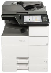
Lexmark MX910de
Рейтинг
Актуальный
Тип устройства
МФУ
Технология печати
лазерная
Макс. формат
A3
Число страниц в месяц
200000
Скорость печати
A4
45
Цветность печати
черно-белая
Общие характеристики |
|
---|---|
Тип устройства |
МФУ |
Печать фотографий |
|
Телефон |
|
Факс |
![]() |
Копир |
![]() |
Сканер |
![]() |
Макс. формат |
A3 |
Технология печати |
лазерная |
Цветность печати |
|
Тип |
лазерный/светодиодный |
Область применения |
большой офис |
Число страниц в месяц |
200 000 |
Размещение |
настольный |
Принтер |
|
Двусторонняя печать |
![]() |
Прямая печать |
![]() |
Печать без полей |
|
Пигментные чернила |
|
Система непрерывной подачи чернил |
|
Макс, разрешение для ч/б печати |
|
По X | 1 200 |
По Y | 1 200 |
Скорость ч/б печати |
|
A4 | 45 |
Время выхода первого отпечатка |
|
Ч/б | 5,6 |
Копир |
|
Макс, количество копий за цикл |
99 |
Шаг масштабирования |
0,01 |
Время выхода первой копии |
5,8 |
Значение масштаба |
|
Максимальное | 4 |
Минимальное | 0,25 |
Макс, разрешение (ч/б) |
|
По X | 600 |
По Y | 600 |
Сканер |
|
Слайд-адаптер |
|
Отправка изображения по e-mail |
|
Стандарт TWAIN |
|
Стандарт WIA |
|
Емкость устройства автоподачи оригиналов |
100 |
Тип сканера |
планшетный/протяжный |
Макс. формат оригинала |
A3 |
Тип датчика сканера |
ПЗС (CCD) |
Устройство автоподачи оригиналов |
двустороннее |
Оттенки серого |
250 |
Макс, размер сканирования |
|
По Y | 432 |
По X | 297 |
Разрешение сканера |
|
По Х | 600 |
Скорость сканирования |
|
Ч/б | 80 |
Цветн, | 80 |
Расходные материалы |
|
Количество картриджей |
1 |
Ресурс ч/б картриджа/тонера |
6 000 |
Печать на: |
|
Этикетках |
![]() |
Конвертах |
![]() |
Карточках |
![]() |
Глянцевой бумаге |
![]() |
Пленках |
![]() |
Матовой бумаге |
![]() |
CD/DVD |
|
Фотобумаге |
|
Рулоне |
|
Плотность бумаги |
|
Максимальная | 256 |
Минимальная | 60 |
Факс |
|
Цветной |
|
PC Fax |
|
Телефон |
|
Автоответчик |
|
Caller ID |
|
АОН |
|
Беспроводная трубка |
|
Проводная трубка |
|
Стандарт DECT |
|
Спикерфон |
|
Шрифты и языки управления |
|
Языки управления |
|
PostScript 3 |
![]() |
PPDS |
![]() |
PCL 5e |
![]() |
PostScript |
![]() |
PCL 6 |
![]() |
![]() |
|
PCL 5c |
|
PostScript 2 |
|
Количество установленных шрифтов |
|
PCL | 89 |
PostScript | 158 |
PPDS | 44 |
Лотки |
|
Емкость лотка ручной подачи |
150 |
Подача бумаги |
|
Стандартная | 1 150 |
Максимальная | 6 650 |
Вывод бумаги |
|
Максимальный | 3 500 |
Стандартный | 250 |
Финишер |
|
Степлер |
![]() |
Сортировка со сдвигом |
![]() |
Электронная сортировка |
![]() |
Брошюровщик |
![]() |
Сортер |
|
Интерфейсы |
|
AirPrint |
![]() |
Поддержка iOS |
![]() |
Веб-интерфейс |
![]() |
Ethernet (RJ-45) |
![]() |
USB |
![]() |
LPT |
|
RS-232 |
|
Wi-Fi |
|
Wi-Fi 802.11n |
|
Bluetooth |
|
Устройство для чтения карт памяти |
|
FireWire (IEEE 1394) |
|
Инфракрасный порт |
|
Версия USB |
2,0 |
Количество слотов расширения |
1 |
Количество свободных слотов расширения |
1 |
Память/Процессор |
|
Макс, объем памяти |
3 072 |
Объем памяти |
1 024 |
Частота процессора |
800 |
Процессор |
Dual Core |
Дополнительная информация |
|
Работа от аккумулятора |
|
Экран |
|
Диагональ дисплея |
9,8 |
Поддержка ОС |
|
Linux |
![]() |
Mac OS |
![]() |
Windows |
![]() |
DOS |
|
Потребляемая мощность |
|
В режиме ожидания | 220 |
При работе | 880 |
Уровень шума |
|
В режиме ожидания | 29 |
При работе | 57 |
Габариты |
|
Ширина |
615 |
Вес |
95 |
Глубина |
697 |
Высота |
909 |
Модули
2500-sheet tray paper pick 3
ADF CIS 3
ADF covers 2
Duplex 1
Toner cartridge drive
2 x 500sheet tray Covers
2 x 500sheet tray Paper feed
Duplex 2
ADF paper transport 4
500-sheet tray Tray 1
CONTROL PANEL 2
2 x 500sheet tray Paper pick 1
Flatbed scanner 3
2 x 500sheet tray Frame
Tray 2 feed
2 x 500sheet tray Tray 3
MPF 1
Fuser drive 1
ADF paper transport 2
2500-sheet tray paper pick 2
Transfer
2500-sheet tray covers
3000 sheet tray Frame 2
3000 sheet tray Paper feed 1
Tray 1 feed
Toner supply 2
Flatbed scanner 1
2500-sheet tray paper feed
2500-sheet tray insert 2
Exit 1
2500-sheet tray insert 4
Flatbed scanner covers
Electrical 2
ADF paper transport 3
Main and feed drive
2 x 500sheet tray Tray 3 or Tray 4 frame
Transfer belt
Photoconductor lock
2 x 500sheet tray Paper pick 2
31: Fuser
3000 sheet tray Frame 1
Covers 2
ADF paper pick 3
Developer
ADF covers 1
ADF paper pick 2
Tray paper detection
Tray 1 separator
3000 sheet tray Paper transport
2500-sheet tray paper transport
ADF paper feed
ADF paper transport 6
Covers 1
Main power supply
Inner Covers
3000 sheet tray Elevator rear section
2500-sheet tray paper pick 1
Flatbed scanner 2
Right door transport
REGISTRATION UNIT
3000 sheet tray Elevator front section
Waste toner
2 x 500sheet tray Paper transport
Electrical 1
2 x 500sheet tray Paper pick 3
Printhead
2500-sheet tray insert 3
Fuser drive 2
Exit 2
High voltage
Tray 2 separator
2 x 500sheet tray Tray 4
Tray 1 and 2 transport
ADF CIS 2
ADF paper transport 5
MPF 2
3000 sheet tray Drive section
ADF CIS 1
3000 sheet tray Paper feed 2
3000 sheet tray Covers
2 x 500sheet tray Paper size detection
OZONE DUCT
500sheet tray Tray 2
500sheet tray Tray 1 or Tray 2
Toner supply 1
Tray rail
ADF paper pick 1
2500-sheet tray insert 1
ADF paper transport 1
Registration transport
2500-sheet tray frame
Control panel 1
Детали
Деталь: | Motor (ADF CIS clean) |
Парткод: | 40X9220 |
Деталь: | ADF CIS clean motor cable |
Парткод: | 40X9699 |
Деталь: | ADF CIS clean sensor cable |
Парткод: | 40X9700 |
Деталь: | ADF CIS clean belt |
Парткод: | 40X9691 |
Деталь: | ADF exit sensor cable |
Парткод: | 40X9701 |
Деталь: | ADF CIS clean roller primary gear |
Парткод: | 40X9959 |
Деталь: | ADF CIS clean roller belt |
Парткод: | 40X9960 |
Деталь: | ADF CIS clean roller secondary gear |
Парткод: | 40X9961 |
Деталь: | Sensor (ADF CIS clean) |
Парткод: | 40X8869 |
Деталь: | ADF CIS clean cam |
Парткод: | 40X9958 |
Деталь: | ADF CIS clean gear |
Парткод: | 40X9957 |
Деталь: | ADF cushion |
Парткод: | 40X8866 |
Деталь: | Duplex transport assembly |
Парткод: | 40X9031 |
Деталь: | Right door cover |
Парткод: | 40X9997 |
Деталь: | Duplex transport jam removal knob |
Парткод: | 40X9998 |
Деталь: | Duplex transport gear |
Парткод: | 40X9012 |
Деталь: | Duplex transport belt |
Парткод: | 40X9036 |
Деталь: | Motor (duplex transport) |
Парткод: | 40X9037 |
Деталь: | TONER CARTRIDGE DRIVE ASSEMBLY |
Парткод: | 40X9223 |
Деталь: | Motor (toner cartridge) |
Парткод: | 40X9179 |
Деталь: | 2 x 500-sheet tray rear right cover |
Парткод: | 40X9779 |
Деталь: | 2 x 500-sheet tray bottom right cover |
Парткод: | 40X9285 |
Деталь: | 2 x 500-sheet tray caster wheel |
Парткод: | 40X9282 |
Деталь: | 2 x 500-sheet tray empty LED mount |
Парткод: | 40X9286 |
Деталь: | 2 x 500-sheet tray empty LED |
Парткод: | 40X8903 |
Деталь: | 2 x 500-sheet tray empty LED cover |
Парткод: | 40X9287 |
Деталь: | 2 x 500-sheet tray empty LED cable |
Парткод: | 40X9289 |
Деталь: | Printer rubber stopper |
Парткод: | 40X9283 |
Деталь: | 2 x 500-sheet tray left cover |
Парткод: | 40X9281 |
Деталь: | 2 x 500-sheet tray rear cover |
Парткод: | 40X9280 |
Деталь: | 2 x 500-sheet tray feed and transport motor belt |
Парткод: | 40X9294 |
Деталь: | 2 x 500-sheet tray feed and transport primary gear |
Парткод: | 40X9891 |
Деталь: | 2 x 500-sheet tray feed and transport secondary gear |
Парткод: | 40X9295 |
Деталь: | Motor (2 x 500-sheet tray 4 feed) |
Парткод: | 40X9293 |
Деталь: | Motor (2 x 500-sheet tray 4 transport) |
Парткод: | 40X9293 |
Деталь: | 2 x 500-sheet tray 4 feed and transport motor cable |
Парткод: | 40X9774 |
Деталь: | 2 x 500-sheet tray 3 feed and transport motor cable |
Парткод: | 40X9882 |
Деталь: | Motor (2 x 500-sheet tray 3 feed) |
Парткод: | 40X9293 |
Деталь: | Motor (2 x 500-sheet tray 3 transport) |
Парткод: | 40X9293 |
Деталь: | Fuser exit sensor cable |
Парткод: | 40X9723 |
Деталь: | Sensor (fuser exit) |
Парткод: | 40X8869 |
Деталь: | Fuser exit sensor actuator |
Парткод: | 40X9039 |
Деталь: | Redrive diverter gear |
Парткод: | 40X9215 |
Деталь: | Sensor (duplex pass through 1) |
Парткод: | 40X8869 |
Деталь: | Motor (ADF scan shaft release) |
Парткод: | 40X8896 |
Деталь: | ADF door open sensor cable |
Парткод: | 40X9689 |
Деталь: | Sensor (ADF top cover open) |
Парткод: | 40X8869 |
Деталь: | Sensor (ADF scan shaft home) |
Парткод: | 40X8869 |
Деталь: | Tray insert guide wheel |
Парткод: | 40X9305 |
Деталь: | Tray 1 insert |
Парткод: | 40X8990 |
Деталь: | Pick roller |
Парткод: | 40X9925 |
Деталь: | Feed/separator roller |
Парткод: | 40X8970 |
Деталь: | Control panel cover assembly |
Парткод: | 41X0452 |
Деталь: | Control panel UICC |
Парткод: | 41X0455 |
Деталь: | Control panel cable kit |
Парткод: | 41X0453 |
Деталь: | Control panel touch screen display (10 in.) |
Парткод: | 41X0454 |
Деталь: | Sensor (2 x 500-sheet tray jam access door) |
Парткод: | 40X9313 |
Деталь: | 2 x 500-sheet tray transport gear spring |
Парткод: | 40X9892 |
Деталь: | 2 x 500-sheet tray transport gear bushing |
Парткод: | 40X9893 |
Деталь: | 2 x 500-sheet tray feed primary gear |
Парткод: | 40X9894 |
Деталь: | 2 x 500-sheet tray cable harness |
Парткод: | 40X9890 |
Деталь: | 2 x 500-sheet tray feed secondary gear |
Парткод: | 40X9295 |
Деталь: | 2 x 500-sheet tray transport gear |
Парткод: | 40X9298 |
Деталь: | Scanner drive motor cable |
Парткод: | 40X9975 |
Деталь: | Motor (scanner drive) |
Парткод: | 40X8940 |
Деталь: | Scanner carriage belt |
Парткод: | 40X8941 |
Деталь: | Scanner carriage gear |
Парткод: | 40X8942 |
Деталь: | Scanner mirror |
Парткод: | 40X9976 |
Деталь: | 2 x 500-sheet tray right rail guide wheel |
Парткод: | 40X8981 |
Деталь: | 2 x 500-sheet tray insert stopper |
Парткод: | 40X9014 |
Деталь: | 2 x 500-sheet tray left rail guide wheel |
Парткод: | 40X9305 |
Деталь: | 2 x 500-sheet tray controller board |
Парткод: | 40X9290 |
Деталь: | 2 x 500-sheet tray interface cable |
Парткод: | 40X9783 |
Деталь: | Tray 2 transport roller |
Парткод: | 40X9983 |
Деталь: | Tray 2 transport sensor cable |
Парткод: | 40X9984 |
Деталь: | Sensor (tray 2 transport) |
Парткод: | 40X8968 |
Деталь: | Sensor (tray 2 paper feed) |
Парткод: | 40X8968 |
Деталь: | Tray 2 empty sensor actuator |
Парткод: | 40X9899 |
Деталь: | FEED ROLLER |
Парткод: | 40X8970 |
Деталь: | Roller clutch |
Парткод: | 40X9981 |
Деталь: | Pick roller |
Парткод: | 40X9925 |
Деталь: | Tray set actuator |
Парткод: | 40X9982 |
Деталь: | Tray 2 paper feed clutch |
Парткод: | 40X8971 |
Деталь: | Paper feed sensor cable |
Парткод: | 40X9987 |
Деталь: | Sensor (tray 2 lift plate level) |
Парткод: | 40X8869 |
Деталь: | Sensor (tray 2 empty) |
Парткод: | 40X8869 |
Деталь: | Tray 3 insert |
Парткод: | 40X9635 |
Деталь: | Tray lock lever |
Парткод: | 40X9304 |
Деталь: | Tray 3 right front cover |
Парткод: | 40X9017 |
Деталь: | Tray 3 handle cover |
Парткод: | 40X9034 |
Деталь: | Tray handle |
Парткод: | 40X9186 |
Деталь: | Tray 3 front cover |
Парткод: | 40X8871 |
Деталь: | Tray insert guide wheel |
Парткод: | 40X9305 |
Деталь: | MPF |
Парткод: | 40X9027 |
Деталь: | MPF lift plate sensor cable |
Парткод: | 40X9716 |
Деталь: | MPF lift plate cam |
Парткод: | 40X9996 |
Деталь: | MPF feed roller |
Парткод: | 40X9995 |
Деталь: | MPF feed clutch gear |
Парткод: | 40X9719 |
Деталь: | MPF separator idler gear |
Парткод: | 40X9718 |
Деталь: | MPF separator gear |
Парткод: | 40X9022 |
Деталь: | MPF feed clutch |
Парткод: | 40X9023 |
Деталь: | MPF lift plate clutch |
Парткод: | 40X9720 |
Деталь: | MPF lift plate solenoid |
Парткод: | 40X9024 |
Деталь: | Sensor (MPF lift plate) |
Парткод: | 40X8869 |
Деталь: | Fuser drive gearbox |
Парткод: | 40X9177 |
Деталь: | Fuser pressure primary gear |
Парткод: | 40X9729 |
Деталь: | Fuser pressure secondary gear |
Парткод: | 40X9730 |
Деталь: | Fuser transport primary gear |
Парткод: | 40X9731 |
Деталь: | Fuser transport secondary gear |
Парткод: | 40X9732 |
Деталь: | ADF feed motor cable |
Парткод: | 40X9683 |
Деталь: | Motor (ADF feed) |
Парткод: | 40X8884 |
Деталь: | ADF feed belt |
Парткод: | 40X8885 |
Деталь: | ADF feed gear |
Парткод: | 40X9950 |
Деталь: | ADF registration roller |
Парткод: | 40X9951 |
Деталь: | ADF registration belt |
Парткод: | 40X8885 |
Деталь: | ADF registration gear |
Парткод: | 40X9952 |
Деталь: | Motor (ADF scan) |
Парткод: | 40X8887 |
Деталь: | ADF registration motor cable |
Парткод: | 40X8888 |
Деталь: | 2500-sheet tray transport roller |
Парткод: | 40X9299 |
Деталь: | Sensor (2500-sheet tray feed) |
Парткод: | 40X8968 |
Деталь: | Sensor (2500-sheet tray transport) |
Парткод: | 40X8968 |
Деталь: | 2500-sheet tray pick assembly sensor cable |
Парткод: | 40X9787 |
Деталь: | Sensor (2500-sheet tray main tray elevator limit) |
Парткод: | 40X8869 |
Деталь: | Sensor (2500-sheet tray main tray empty, top) |
Парткод: | 40X8869 |
Деталь: | 2500-sheet tray main tray top empty actuator |
Парткод: | 40X9899 |
Деталь: | FEED ROLLER |
Парткод: | 40X8970 |
Деталь: | Pick roller |
Парткод: | 40X9925 |
Деталь: | Roller clutch |
Парткод: | 40X9981 |
Деталь: | 2500-sheet tray tray set actuator |
Парткод: | 40X9982 |
Деталь: | Registration unit assembly |
Парткод: | 40X9011 |
Деталь: | Fusing speed sensor cable |
Парткод: | 40X9990 |
Деталь: | Fuser fixed power resistor |
Парткод: | 40X9009 |
Деталь: | Sensor (fusing speed) |
Парткод: | 40X8869 |
Деталь: | TRANSFER ROLLER |
Парткод: | 40X9010 |
Деталь: | 2500-sheet tray rear cover |
Парткод: | 40X9280 |
Деталь: | 2500-sheet tray rear right cover |
Парткод: | 40X9779 |
Деталь: | 2500-sheet tray bottom right cover |
Парткод: | 40X9285 |
Деталь: | Caster wheel |
Парткод: | 40X9282 |
Деталь: | 2500-sheet tray LED mount |
Парткод: | 40X9286 |
Деталь: | Tray empty LED |
Парткод: | 40X8903 |
Деталь: | 2500-sheet tray LED cover |
Парткод: | 40X9287 |
Деталь: | Tray empty LED cable |
Парткод: | 40X9782 |
Деталь: | TRAY STOPPER |
Парткод: | 40X9283 |
Деталь: | 2500-sheet tray left cover |
Парткод: | 40X9281 |
Деталь: | Dehumidifier |
Парткод: | 40X9261 |
Деталь: | 3000-sheet tray feed and pick drive gear |
Парткод: | 40X9886 |
Деталь: | Feed and pick roller |
Парткод: | 40X9267 |
Деталь: | 3000-sheet tray empty sensor actuator |
Парткод: | 40X9881 |
Деталь: | 3000-sheet tray roller clutch |
Парткод: | 40X9297 |
Деталь: | 3000-sheet tray pick gear |
Парткод: | 40X9048 |
Деталь: | 3000-sheet tray feed and pick belt |
Парткод: | 40X9268 |
Деталь: | 3000-sheet tray feed gear |
Парткод: | 40X9772 |
Деталь: | Tray 1 paper feed clutch |
Парткод: | 40X8971 |
Деталь: | Tray 1 sensor cables |
Парткод: | 40X8972 |
Деталь: | Sensor (tray 1 lift plate level) |
Парткод: | 40X8869 |
Деталь: | Tray empty sensor actuator |
Парткод: | 40X9899 |
Деталь: | Sensor (tray 1 paper feed) |
Парткод: | 40X8968 |
Деталь: | Sensor (tray 1 empty) |
Парткод: | 40X8869 |
Деталь: | Tray feed roller |
Парткод: | 40X8970 |
Деталь: | Tray pick roller |
Парткод: | 40X9925 |
Деталь: | Roller clutch |
Парткод: | 40X9981 |
Деталь: | Tray set actuator |
Парткод: | 40X9982 |
Деталь: | Toner supply motor cable |
Парткод: | 40X8957 |
Деталь: | Motor (toner supply) |
Парткод: | 40X8956 |
Деталь: | Toner cartridge present sensor cable |
Парткод: | 40X9751 |
Деталь: | Sensor (toner cartridge present) |
Парткод: | 40X8869 |
Деталь: | ADF duplex scan glass |
Парткод: | 40X8933 |
Деталь: | Scanner glass |
Парткод: | 40X8928 |
Деталь: | Scanner sensor cable |
Парткод: | 40X9702 |
Деталь: | Sensor (scanner paper length 1) |
Парткод: | 40X8932 |
Деталь: | Sensor (scanner cover switch) |
Парткод: | 40X8930 |
Деталь: | Sensor (scanner paper length 2) |
Парткод: | 40X8932 |
Деталь: | Scanner controller board |
Парткод: | 40X8934 |
Деталь: | Sensor (scanner lamp home) |
Парткод: | 40X8869 |
Деталь: | Scanner cover open sensor actuator |
Парткод: | 40X8931 |
Деталь: | Sensor (scanner cover open) |
Парткод: | 40X9313 |
Деталь: | Motor (2500-sheet tray feed) |
Парткод: | 40X9293 |
Деталь: | Motor (2500-sheet tray transport) |
Парткод: | 40X9293 |
Деталь: | 2500-sheet tray feed and transport motor belt |
Парткод: | 40X9294 |
Деталь: | 2500-sheet tray feed and transport primary gear |
Парткод: | 40X9891 |
Деталь: | 2500-sheet tray feed and transport secondary gear |
Парткод: | 40X9295 |
Деталь: | Motor (2500-sheet tray elevator) |
Парткод: | 40X9896 |
Деталь: | Motor (2500-sheet tray transfer guide) |
Парткод: | 40X9896 |
Деталь: | 2500-sheet tray feed and transport motor cable |
Парткод: | 40X9882 |
Деталь: | Paper stack transfer sensor actuator spring |
Парткод: | 40X9794 |
Деталь: | Sensor (main tray near empty) |
Парткод: | 40X8869 |
Деталь: | Paper stack transfer guide |
Парткод: | 40X9792 |
Деталь: | Paper stack transfer guide base |
Парткод: | 40X9791 |
Деталь: | Paper stack transfer sensor actuator (A4) |
Парткод: | 40X9793 |
Деталь: | Paper stack transfer sensor actuator (LTR) |
Парткод: | 40X9263 |
Деталь: | Sensor (paper stack transfer) |
Парткод: | 40X8869 |
Деталь: | Reserve tray paper limit sensor actuator spring |
Парткод: | 40X9883 |
Деталь: | Sensor (reserve tray paper limit) |
Парткод: | 40X8869 |
Деталь: | Reserve tray paper limit sensor actuator |
Парткод: | 40X9900 |
Деталь: | Redrive exit guide |
Парткод: | 40X9167 |
Деталь: | Sensor (redrive exit) |
Парткод: | 40X9313 |
Деталь: | Redrive exit sensor cable |
Парткод: | 40X9644 |
Деталь: | Redrive exit sensor actuator |
Парткод: | 40X9714 |
Деталь: | HPT bin paper bail |
Парткод: | 40X9042 |
Деталь: | Sensor (exit) |
Парткод: | 40X9313 |
Деталь: | Exit sensor cable |
Парткод: | 40X9599 |
Деталь: | Exit sensor actuator |
Парткод: | 40X9484 |
Деталь: | Standard bin paper bail |
Парткод: | 40X8974 |
Деталь: | Exit sensor housing |
Парткод: | 40X8895 |
Деталь: | Exit clutch belt |
Парткод: | 40X9156 |
Деталь: | Redrive belt |
Парткод: | 40X9724 |
Деталь: | Motor (redrive) |
Парткод: | 40X9155 |
Деталь: | Paper exit fan |
Парткод: | 40X8859 |
Деталь: | 2500-sheet tray main tray empty sensor bottom actuator |
Парткод: | 40X9802 |
Деталь: | 2500-sheet tray elevator home sensor actuator |
Парткод: | 40X9801 |
Деталь: | Sensor (main tray empty, bottom) |
Парткод: | 40X8869 |
Деталь: | Sensor (2500-sheet tray elevator home) |
Парткод: | 40X8869 |
Деталь: | Tray insert bottom right guide wheel |
Парткод: | 40X9799 |
Деталь: | 2500-sheet tray transfer guide stop spring |
Парткод: | 40X9804 |
Деталь: | 2500-sheet tray transfer guide stop |
Парткод: | 40X9803 |
Деталь: | Transfer guide belt |
Парткод: | 40X9808 |
Деталь: | Sensor (reserve tray empty) |
Парткод: | 40X8869 |
Деталь: | Sensor (2500.sheet tray transfer guide home) |
Парткод: | 40X8869 |
Деталь: | Reserve tray empty sensor actuator |
Парткод: | 40X9900 |
Деталь: | Reserve tray empty sensor actuator spring |
Парткод: | 40X9883 |
Деталь: | Tray insert bottom left guide wheel |
Парткод: | 40X9805 |
Деталь: | Tray insert guide wheel |
Парткод: | 40X9305 |
Деталь: | 2500-sheet tray tray insert sensor cable |
Парткод: | 40X9809 |
Деталь: | 2500-sheet tray elevator damper |
Парткод: | 40X9806 |
Деталь: | 2500-sheet tray elevator home sensor actuator spring |
Парткод: | 40X9800 |
Деталь: | Scanner rear cover |
Парткод: | 40X8921 |
Деталь: | Scanner top cover |
Парткод: | 40X8922 |
Деталь: | Scanner right cover |
Парткод: | 40X8923 |
Деталь: | Screw hole cover |
Парткод: | 40X8924 |
Деталь: | CONTROL PANEL BASE |
Парткод: | 40X8925 |
Деталь: | Control panel mount |
Парткод: | 40X9972 |
Деталь: | Cave light LED cable |
Парткод: | 40X9974 |
Деталь: | Cave light lens |
Парткод: | 40X9971 |
Деталь: | Control panel bottom cover |
Парткод: | 40X9973 |
Деталь: | Scanner left cover |
Парткод: | 40X8926 |
Деталь: | Engine controller board |
Парткод: | 40X9207 |
Деталь: | Engine controller board FFC |
Парткод: | 40X9744 |
Деталь: | ADF/scanner image controller board |
Парткод: | 40X9210 |
Деталь: | Controller board (MFP) |
Парткод: | 40X9663 |
Деталь: | Controller board fan |
Парткод: | 40X9209 |
Деталь: | Motor (ADF registration) |
Парткод: | 40X8889 |
Деталь: | ADF scan motor cable |
Парткод: | 40X9684 |
Деталь: | ADF scan roller 2 gear |
Парткод: | 40X9686 |
Деталь: | ADF scan roller 2 |
Парткод: | 40X8893 |
Деталь: | ADF document exit roller |
Парткод: | 40X8891 |
Деталь: | ADF scan/exit roller belt |
Парткод: | 40X8892 |
Деталь: | ADF exit roller gear |
Парткод: | 40X9687 |
Деталь: | ADF scan roller 3 gear |
Парткод: | 40X9688 |
Деталь: | ADF scan roller 1 |
Парткод: | 40X8894 |
Деталь: | ADF scan motor gear |
Парткод: | 40X9685 |
Деталь: | ADF scan motor belt |
Парткод: | 40X8890 |
Деталь: | MAIN DRIVE ASSEMBLY |
Парткод: | 40X9164 |
Деталь: | Motor (developer) |
Парткод: | 40X9564 |
Деталь: | Motor (transport) |
Парткод: | 40X9163 |
Деталь: | Duplex transport clutch |
Парткод: | 40X9166 |
Деталь: | Transport motor gear |
Парткод: | 40X9165 |
Деталь: | Duplex transport clutch gear |
Парткод: | 40X9725 |
Деталь: | Feed motor belt |
Парткод: | 40X9173 |
Деталь: | Motor (feed) |
Парткод: | 40X9170 |
Деталь: | Motor (registration) |
Парткод: | 40X9171 |
Деталь: | Feed motor gear |
Парткод: | 40X9726 |
Деталь: | Feed drive belt |
Парткод: | 40X9174 |
Деталь: | Feed drive assembly |
Парткод: | 40X9727 |
Деталь: | Motor (tray 2 transport) |
Парткод: | 40X9170 |
Деталь: | Tray 2 transport drive belt |
Парткод: | 40X9639 |
Деталь: | Tray 2 transport drive assembly |
Парткод: | 40X9728 |
Деталь: | 2 x 500-sheet tray near empty sensor actuator |
Парткод: | 40X9308 |
Деталь: | Tray insert paper length guide |
Парткод: | 40X9306 |
Деталь: | 2 x 500-tray insert paper length sensor actuator |
Парткод: | 40X9309 |
Деталь: | Transfer belt cable |
Парткод: | 40X8963 |
Деталь: | Transfer belt maintenance kit |
Парткод: | 40X9704 |
Деталь: | Transfer belt paper guide |
Парткод: | 40X9979 |
Деталь: | Photoconductor relay contact |
Парткод: | 40X8962 |
Деталь: | Photoconductor release lever |
Парткод: | 40X9978 |
Деталь: | Photoconductor cable |
Парткод: | 40X8961 |
Деталь: | Sensor (2 x 500-sheet tray transport) |
Парткод: | 40X8968 |
Деталь: | Sensor (2 x 500-sheet tray feed) |
Парткод: | 40X8968 |
Деталь: | Sensor (2 x 500-sheet tray empty) |
Парткод: | 40X8869 |
Деталь: | 2 x 500-sheet tray empty sensor actuator |
Парткод: | 40X9899 |
Деталь: | Roller clutch |
Парткод: | 40X9981 |
Деталь: | FEED ROLLER |
Парткод: | 40X8970 |
Деталь: | Pick roller |
Парткод: | 40X9925 |
Деталь: | 2 x 500-sheet tray set actuator |
Парткод: | 40X9982 |
Деталь: | Sensor (2 x 500-sheet tray lift plate level) |
Парткод: | 40X8869 |
Деталь: | 2 x 500-sheet tray 3 pick assembly sensor cable |
Парткод: | 40X9316 |
Деталь: | 2 x 500-sheet tray 4 pick assembly sensor cable |
Парткод: | 40X9300 |
Деталь: | 2 x 500-sheet tray transport roller |
Парткод: | 40X9299 |
Деталь: | Fuser |
Парткод: | 40X9046 |
Деталь: | Induction heater, 100 V |
Парткод: | 40X9044 |
Деталь: | Induction heater, 230 V |
Парткод: | 40X9045 |
Деталь: | Sensor (fuser temperature) with cable |
Парткод: | 40X9047 |
Деталь: | FUSER FAN |
Парткод: | 40X9041 |
Деталь: | 3000-sheet tray caster wheel |
Парткод: | 40X9279 |
Деталь: | Bin side cover |
Парткод: | 40X8914 |
Деталь: | Finisher interface cable |
Парткод: | 40X8907 |
Деталь: | UPPER REAR COVER |
Парткод: | 40X8908 |
Деталь: | Scanner interface cable cover |
Парткод: | 40X9762 |
Деталь: | Engine board cover |
Парткод: | 40X8909 |
Деталь: | Controller board access cover |
Парткод: | 40X8910 |
Деталь: | Port mount |
Парткод: | 40X8912 |
Деталь: | Port access door |
Парткод: | 40X9763 |
Деталь: | ADF feed and pick roller assembly |
Парткод: | 40X8878 |
Деталь: | ADF pick roller |
Парткод: | 40X8879 |
Деталь: | ADF feed roller |
Парткод: | 40X9681 |
Деталь: | ADF pick belt |
Парткод: | 40X8880 |
Деталь: | Erase LED |
Парткод: | 40X8960 |
Деталь: | Erase LED cable |
Парткод: | 40X9977 |
Деталь: | Developer unit |
Парткод: | 40X9936 |
Деталь: | ADF REAR COVER |
Парткод: | 40X8858 |
Деталь: | ADF controller board |
Парткод: | 40X8860 |
Деталь: | ADF right hinge |
Парткод: | 40X8861 |
Деталь: | ADF frame |
Парткод: | 40X8862 |
Деталь: | ADF FRONT COVER |
Парткод: | 40X8863 |
Деталь: | ADF left hinge |
Парткод: | 40X8864 |
Деталь: | ADF fan |
Парткод: | 40X9041 |
Деталь: | ADF CIS cable |
Парткод: | 40X9678 |
Деталь: | ADF sensor cable |
Парткод: | 40X9679 |
Деталь: | ADF top cover sensor cable |
Парткод: | 40X9680 |
Деталь: | Sensor (ADF document separation) |
Парткод: | 40X8869 |
Деталь: | Sensor (ADF registration) |
Парткод: | 40X8869 |
Деталь: | Sensor (ADF tray empty) |
Парткод: | 40X8869 |
Деталь: | Sensor (ADF mixed paper width 1) |
Парткод: | 40X8869 |
Деталь: | Sensor (ADF mixed paper width 2) |
Парткод: | 40X8869 |
Деталь: | Sensor (ADF mixed paper width 3) |
Парткод: | 40X8869 |
Деталь: | ADF registration idler roller |
Парткод: | 40X9948 |
Деталь: | ADF ground cable |
Парткод: | 40X8877 |
Деталь: | Tray size sensing assembly |
Парткод: | 40X8988 |
Деталь: | Tray 1 feed cable |
Парткод: | 40X8984 |
Деталь: | Motor (tray 1 lift) |
Парткод: | 40X8987 |
Деталь: | Sensor (tray 1 near empty) |
Парткод: | 40X8869 |
Деталь: | Sensor (tray 1 paper width) |
Парткод: | 40X8989 |
Деталь: | Motor (tray 2 lift) |
Парткод: | 40X8987 |
Деталь: | Sensor (tray 2 near empty) |
Парткод: | 40X8869 |
Деталь: | Sensor (tray 2 paper width) |
Парткод: | 40X8989 |
Деталь: | Tray 2 feed cable |
Парткод: | 40X8984 |
Деталь: | Sensor (tray 2 paper length) |
Парткод: | 40X8985 |
Деталь: | Sensor (tray 1 paper length) |
Парткод: | 40X8985 |
Деталь: | Roller clutch |
Парткод: | 40X9455 |
Деталь: | Separator Roller |
Парткод: | 40X8970 |
Деталь: | Separator roller assembly |
Парткод: | 40X9927 |
Деталь: | 3000-sheet tray transport roller |
Парткод: | 40X9273 |
Деталь: | Sensor (3000-sheet tray feed) |
Парткод: | 40X9885 |
Деталь: | 3000-sheet tray transport idler roller |
Парткод: | 40X9771 |
Деталь: | 3000-sheet tray set sensor actuator spring |
Парткод: | 40X9373 |
Деталь: | 3000-sheet tray set sensor actuator |
Парткод: | 40X9040 |
Деталь: | Sensor (3000-sheet tray set) |
Парткод: | 40X9880 |
Деталь: | 3000-sheet tray feed sensor cable |
Парткод: | 40X8929 |
Деталь: | 3000-sheet tray transport roller drive gear |
Парткод: | 40X9769 |
Деталь: | 2500-sheet tray jam access door strap |
Парткод: | 40X9908 |
Деталь: | Transport idler roller |
Парткод: | 40X8973 |
Деталь: | ADF rear paper guide |
Парткод: | 40X9940 |
Деталь: | ADF tray |
Парткод: | 40X9941 |
Деталь: | ADF front paper guide |
Парткод: | 40X9942 |
Деталь: | Sensor (ADF paper length 2) |
Парткод: | 40X8869 |
Деталь: | Sensor (ADF paper length 1) |
Парткод: | 40X8868 |
Деталь: | ADF paper length 2 sensor actuator (Legal) |
Парткод: | 40X8872 |
Деталь: | ADF paper length 2 sensor actuator (A4) |
Парткод: | 40X9748 |
Деталь: | ADF bin paper stopper |
Парткод: | 40X9943 |
Деталь: | ADF tray bottom cover |
Парткод: | 40X9944 |
Деталь: | Sensor (ADF paper width) |
Парткод: | 40X8870 |
Деталь: | ADF paper guide gear |
Парткод: | 40X9747 |
Деталь: | ADF paper guide rack |
Парткод: | 40X9945 |
Деталь: | ADF tray cable |
Парткод: | 40X8873 |
Деталь: | ADF transport gear |
Парткод: | 40X9685 |
Деталь: | ADF exit roller |
Парткод: | 40X9953 |
Деталь: | CIS glass clean motor cable |
Парткод: | 40X9695 |
Деталь: | ADF glass clean encoder belt |
Парткод: | 40X9691 |
Деталь: | Motor (CIS glass clean) |
Парткод: | 40X9213 |
Деталь: | CIS glass clean belt |
Парткод: | 40X9214 |
Деталь: | CIS glass clean gear |
Парткод: | 40X9693 |
Деталь: | ADF glass clean encoder |
Парткод: | 40X9694 |
Деталь: | Standard bin |
Парткод: | 40X9924 |
Деталь: | Tray empty board cable |
Парткод: | 40X8901 |
Деталь: | Tray empty board mount |
Парткод: | 40X9758 |
Деталь: | Tray 1 empty indicator |
Парткод: | 40X8903 |
Деталь: | Tray empty board cover |
Парткод: | 40X8902 |
Деталь: | Tray 2 empty indicator |
Парткод: | 40X8903 |
Деталь: | FRONT LOWER COVER |
Парткод: | 40X8904 |
Деталь: | Screwdriver |
Парткод: | 40X9962 |
Деталь: | Bottom front door |
Парткод: | 40X9760 |
Деталь: | Printhead cleaner |
Парткод: | 40X8905 |
Деталь: | Bottom front door hinge |
Парткод: | 40X9761 |
Деталь: | Top front door |
Парткод: | 40X8900 |
Деталь: | Top front door outer hinge |
Парткод: | 40X8906 |
Деталь: | Top front door inner hinge |
Парткод: | 40X9917 |
Деталь: | LEFT COVER |
Парткод: | 40X8898 |
Деталь: | Rear Left Cover |
Парткод: | 40X8899 |
Деталь: | Standard bin base |
Парткод: | 40X8897 |
Деталь: | Main power supply, 100 V |
Парткод: | 40X9203 |
Деталь: | Main power supply, 230 V |
Парткод: | 40X9204 |
Деталь: | Main power supply fan with duct |
Парткод: | 40X9205 |
Деталь: | Main power supply fan |
Парткод: | 40X8945 |
Деталь: | Waste toner bottle latch |
Парткод: | 40X8915 |
Деталь: | Front inner cover |
Парткод: | 40X8916 |
Деталь: | Waste toner door mount |
Парткод: | 40X9764 |
Деталь: | Lower front door strap |
Парткод: | 40X8919 |
Деталь: | Main power switch |
Парткод: | 40X8917 |
Деталь: | Waste toner door switch |
Парткод: | 40X9963 |
Деталь: | Door switch |
Парткод: | 40X9527 |
Деталь: | 3000-sheet tray elevator release spring |
Парткод: | 40X9277 |
Деталь: | 2500-sheet tray transport gear |
Парткод: | 40X9298 |
Деталь: | 2500-sheet tray transport gear spring |
Парткод: | 40X9892 |
Деталь: | 2500-sheet tray transport gear bushing |
Парткод: | 40X9893 |
Деталь: | Sensor (2500-sheet tray jam access door) |
Парткод: | 40X9313 |
Деталь: | 2500-sheet tray feed primary gear |
Парткод: | 40X9894 |
Деталь: | 2500-sheet tray feed secondary gear |
Парткод: | 40X9295 |
Деталь: | 2500-sheet tray cable harness |
Парткод: | 40X9786 |
Деталь: | Scanner lamp cable |
Парткод: | 40X8939 |
Деталь: | Scanner lamp |
Парткод: | 40X8938 |
Деталь: | Scanner CCD lens assembly |
Парткод: | 40X8937 |
Деталь: | Scanner CCD cable |
Парткод: | 40X8935 |
Деталь: | Right door upper lock |
Парткод: | 40X9019 |
Деталь: | Right door switch actuator |
Парткод: | 40X9020 |
Деталь: | Right door handle |
Парткод: | 40X9711 |
Деталь: | Right door lower lock |
Парткод: | 40X9713 |
Деталь: | Right door middle lock |
Парткод: | 40X9712 |
Деталь: | Right door lock support |
Парткод: | 40X9715 |
Деталь: | Tray 2 transport guide |
Парткод: | 40X8920 |
Деталь: | Right door switch |
Парткод: | 40X9527 |
Деталь: | Registration unit gear |
Парткод: | 40X9012 |
Деталь: | Registration unit lock |
Парткод: | 40X9992 |
Деталь: | Registration unit lock shaft |
Парткод: | 40X9993 |
Деталь: | Registration unit handle |
Парткод: | 40X9994 |
Деталь: | Sensor (duplex pass through 2) |
Парткод: | 40X8869 |
Деталь: | Lower registration gear |
Парткод: | 40X9710 |
Деталь: | Registration drive gear |
Парткод: | 40X9991 |
Деталь: | Registration unit belt |
Парткод: | 40X9013 |
Деталь: | 3000-sheet tray release handle |
Парткод: | 40X9275 |
Деталь: | 3000-sheet tray elevator spring |
Парткод: | 40X9276 |
Деталь: | 2 x 500-sheet tray jam access door strap |
Парткод: | 40X9908 |
Деталь: | Transport idler roller |
Парткод: | 40X8973 |
Деталь: | Power socket |
Парткод: | 40X9741 |
Деталь: | Power socket mount |
Парткод: | 40X9402 |
Деталь: | Power socket cable |
Парткод: | 40X9740 |
Деталь: | Transfer belt fan duct |
Парткод: | 40X8944 |
Деталь: | Transfer belt fan |
Парткод: | 40X8945 |
Деталь: | Image controller board |
Парткод: | 40X8946 |
Деталь: | Ozone filter duct |
Парткод: | 40X9188 |
Деталь: | Printhead (MFP) |
Парткод: | 40X8949 |
Деталь: | Printhead FFC |
Парткод: | 40X8948 |
Деталь: | Printhead relay board |
Парткод: | 40X8947 |
Деталь: | Transfer guide primary gear |
Парткод: | 40X9796 |
Деталь: | Main tray elevator coupling |
Парткод: | 40X9798 |
Деталь: | Main tray elevator gear spring |
Парткод: | 40X9901 |
Деталь: | Main tray elevator gear |
Парткод: | 40X9902 |
Деталь: | Transfer guide primary gear spring |
Парткод: | 40X9797 |
Деталь: | Transfer guide secondary gear |
Парткод: | 40X9795 |
Деталь: | Motor (fuser pressure) |
Парткод: | 40X9179 |
Деталь: | Motor (fuser) |
Парткод: | 40X9163 |
Деталь: | Fuser exit clutch |
Парткод: | 40X9178 |
Деталь: | Power.saving board |
Парткод: | 40X9189 |
Деталь: | Induction heater magnetic erase board |
Парткод: | 40X9198 |
Деталь: | Fuser power supply fan |
Парткод: | 40X8945 |
Деталь: | Induction heater power supply cable |
Парткод: | 40X9736 |
Деталь: | Noise filter board cable |
Парткод: | 40X9737 |
Деталь: | Expansion controller board |
Парткод: | 40X9199 |
Деталь: | High voltage board |
Парткод: | 40X9193 |
Деталь: | Noise filter board, 100 V |
Парткод: | 40X9200 |
Деталь: | Noise filter board, 230 V |
Парткод: | 40X9201 |
Деталь: | Induction heater magnetic erase board cable |
Парткод: | 40X9735 |
Деталь: | Induction heater power supply, 100 V |
Парткод: | 40X9196 |
Деталь: | Induction heater power supply , 230 V |
Парткод: | 40X9197 |
Деталь: | High voltage developer contact |
Парткод: | 40X9192 |
Деталь: | High voltage transfer cable |
Парткод: | 40X9733 |
Деталь: | High voltage charge cable |
Парткод: | 40X9194 |
Деталь: | High voltage charge contact |
Парткод: | 40X9191 |
Деталь: | High voltage toner charge cable |
Парткод: | 40X9734 |
Деталь: | Sensor (tray 1 and 2 paper temperature) |
Парткод: | 40X9190 |
Деталь: | Roller clutch |
Парткод: | 40X9455 |
Деталь: | Separator Roller |
Парткод: | 40X8970 |
Деталь: | Separator roller assembly |
Парткод: | 40X9927 |
Деталь: | Tray 4 insert |
Парткод: | 40X9697 |
Деталь: | Tray lock lever |
Парткод: | 40X9304 |
Деталь: | Tray 4 right front cover |
Парткод: | 40X9033 |
Деталь: | Tray 4 handle cover |
Парткод: | 40X9320 |
Деталь: | Tray handle |
Парткод: | 40X9186 |
Деталь: | Tray 4 front cover |
Парткод: | 40X9028 |
Деталь: | Tray insert guide wheel |
Парткод: | 40X9305 |
Деталь: | Tray 2 transport drive gear |
Парткод: | 40X9980 |
Деталь: | Tray 1 and 2 paper feed unit |
Парткод: | 40X8966 |
Деталь: | ADF CIS idler roller |
Парткод: | 40X9948 |
Деталь: | ADF CIS jam access latch |
Парткод: | 40X9956 |
Деталь: | ADF CIS jam access handle |
Парткод: | 40X9955 |
Деталь: | ADF scan sensor cable |
Парткод: | 40X9690 |
Деталь: | ADF exit sensor cable |
Парткод: | 40X9212 |
Деталь: | Sensor (ADF jam access cover) |
Парткод: | 40X8869 |
Деталь: | Sensor (ADF exit) |
Парткод: | 40X8869 |
Деталь: | Sensor (scan glass clean) |
Парткод: | 40X8869 |
Деталь: | Sensor (ADF scan) |
Парткод: | 40X9211 |
Деталь: | Sensor (MPF paper length 1) |
Парткод: | 40X8869 |
Деталь: | MPF paper length 1 sensor actuator |
Парткод: | 40X9026 |
Деталь: | MPF paper length 2 sensor actuator |
Парткод: | 40X9026 |
Деталь: | Sensor (MPF paper length 2) |
Парткод: | 40X8869 |
Деталь: | MPF paper length sensor cable |
Парткод: | 40X9721 |
Деталь: | Sensor (MPF paper width) |
Парткод: | 40X9030 |
Деталь: | MPF separator roller |
Парткод: | 40X9615 |
Деталь: | MPF paper width sensor cable |
Парткод: | 40X9722 |
Деталь: | 3000-sheet tray controller board |
Парткод: | 40X9262 |
Деталь: | 3000.sheet tray door switch |
Парткод: | 40X9266 |
Деталь: | Sensor (3000-sheet tray near empty 1) |
Парткод: | 40X9880 |
Деталь: | Sensor (3000-sheet tray near empty 2) |
Парткод: | 40X9880 |
Деталь: | 3000-sheet tray feed motor idler gear |
Парткод: | 40X9767 |
Деталь: | 3000-sheet tray feed and pick idler gear |
Парткод: | 40X9766 |
Деталь: | 3000-sheet tray feed motor gear |
Парткод: | 40X9768 |
Деталь: | Motor (3000-sheet tray elevator) |
Парткод: | 40X9264 |
Деталь: | Motor (3000-sheet tray feed) |
Парткод: | 40X9269 |
Деталь: | Motor (3000-sheet tray transport) |
Парткод: | 40X9269 |
Деталь: | ADF CIS assembly |
Парткод: | 40X9216 |
Деталь: | ADF CIS data cable |
Парткод: | 40X8865 |
Деталь: | ADF CIS power supply cable |
Парткод: | 40X9218 |
Деталь: | ADF CIS power supply board cable |
Парткод: | 40X9696 |
Деталь: | ADF CIS power supply board |
Парткод: | 40X9217 |
Деталь: | Sensor (3000-sheet tray elevator level) |
Парткод: | 40X9880 |
Деталь: | Sensor (3000-sheet tray empty) |
Парткод: | 40X9880 |
Деталь: | 3000-sheet tray separator roller |
Парткод: | 40X9267 |
Деталь: | 3000-sheet tray separator roller secondary gear |
Парткод: | 40X9887 |
Деталь: | 3000-sheet tray separator belt |
Парткод: | 40X9271 |
Деталь: | 3000-sheet tray separator roller primary gear |
Парткод: | 40X9773 |
Деталь: | 3000-sheet tray separator roller clutch |
Парткод: | 40X9888 |
Деталь: | 3000-sheet tray separator roller drive gear |
Парткод: | 40X9886 |
Деталь: | 3000-sheet tray top door |
Парткод: | 40X9260 |
Деталь: | 3000-sheet tray right cover |
Парткод: | 40X9255 |
Деталь: | 3000-sheet tray empty LED |
Парткод: | 40X8903 |
Деталь: | 3000-sheet tray empty LED cable |
Парткод: | 40X9257 |
Деталь: | 3000-sheet tray empty LED cover |
Парткод: | 40X9884 |
Деталь: | 3000-sheet tray front cover |
Парткод: | 40X9256 |
Деталь: | 3000-sheet tray slit cover |
Парткод: | 40X9259 |
Деталь: | 3000-sheet tray left top cover |
Парткод: | 40X9765 |
Деталь: | 3000-sheet tray rear cover |
Парткод: | 40X9258 |
Деталь: | Motor (2 x 500-sheet tray 3 lift) |
Парткод: | 40X8987 |
Деталь: | Sensor (2 x 500-sheet tray 3 near empty) |
Парткод: | 40X8869 |
Деталь: | Motor (2 x 500-sheet tray 4 lift) |
Парткод: | 40X8987 |
Деталь: | Sensor (2 x 500-sheet tray 4 near empty) |
Парткод: | 40X8869 |
Деталь: | Sensor (2 x 500-sheet tray 4 paper width) |
Парткод: | 40X8989 |
Деталь: | Sensor (2 x 500-sheet tray 4 paper length) |
Парткод: | 40X8985 |
Деталь: | 2 x 500 sheet tray paper length sensor cable |
Парткод: | 40X9775 |
Деталь: | Sensor (2 x 500-sheet tray 3 paper width) |
Парткод: | 40X8989 |
Деталь: | Sensor (2 x 500-sheet tray 3 paper length) |
Парткод: | 40X8985 |
Деталь: | 2 x 500 sheet tray lift motor cable |
Парткод: | 40X9889 |
Деталь: | Exhaust filter |
Парткод: | 40X9184 |
Деталь: | Toner suction fan |
Парткод: | 40X8859 |
Деталь: | OZONE FILTER |
Парткод: | 40X9183 |
Деталь: | Ozone fan |
Парткод: | 40X9185 |
Деталь: | Ozone fan with duct |
Парткод: | 40X9182 |
Деталь: | Tray insert guide wheel |
Парткод: | 40X9305 |
Деталь: | Tray 2 insert |
Парткод: | 40X8992 |
Деталь: | Pick roller |
Парткод: | 40X9925 |
Деталь: | Feed/separator roller |
Парткод: | 40X8970 |
Деталь: | Tray near empty sensor actuator |
Парткод: | 40X9308 |
Деталь: | Tray paper length guide |
Парткод: | 40X9306 |
Деталь: | Sensor (top front door) |
Парткод: | 40X9313 |
Деталь: | Toner cartridge relay contact cable |
Парткод: | 40X9750 |
Деталь: | Toner cartridge contact |
Парткод: | 40X8962 |
Деталь: | Toner agitator |
Парткод: | 40X8951 |
Деталь: | Rear right lift handle |
Парткод: | 40X8978 |
Деталь: | Front right lift handle |
Парткод: | 40X8977 |
Деталь: | Tray 1 insert rail |
Парткод: | 40X8982 |
Деталь: | Tray 2 insert rail |
Парткод: | 40X8982 |
Деталь: | Tray left rail guide wheel |
Парткод: | 40X9305 |
Деталь: | Tray right rail guide wheel |
Парткод: | 40X8981 |
Деталь: | TRAY STOPPER |
Парткод: | 40X9989 |
Деталь: | Front left lift handle |
Парткод: | 40X8979 |
Деталь: | Tray base left cover |
Парткод: | 40X9988 |
Деталь: | Rear left lift handle |
Парткод: | 40X8980 |
Деталь: | ADF top cover |
Парткод: | 40X9946 |
Деталь: | ADF door latch |
Парткод: | 40X8875 |
Деталь: | ADF door frame |
Парткод: | 40X9947 |
Деталь: | 2500-sheet tray insert (LTR) |
Парткод: | 40X9602 |
Деталь: | 2500-sheet tray insert (A4) |
Парткод: | 40X9576 |
Деталь: | 2500-sheet tray front cover |
Парткод: | 40X9789 |
Деталь: | 2500-sheet tray right front cover |
Парткод: | 40X9339 |
Деталь: | 2500-sheet tray handle cover |
Парткод: | 40X9320 |
Деталь: | 2500-sheet tray handle |
Парткод: | 40X9186 |
Деталь: | 2500-sheet tray lock lever |
Парткод: | 40X9788 |
Деталь: | ADF separator pad |
Парткод: | 40X8882 |
Деталь: | ADF registration guide |
Парткод: | 40X9949 |
Деталь: | ADF separator roller |
Парткод: | 40X9682 |
Деталь: | Registration transport assembly |
Парткод: | 40X8994 |
Деталь: | Registration primary gear |
Парткод: | 40X9706 |
Деталь: | Registration secondary gear |
Парткод: | 40X9707 |
Деталь: | Registration roller fixed power resistor |
Парткод: | 40X9009 |
Деталь: | Registration cable |
Парткод: | 40X9007 |
Деталь: | Toner density solenoid |
Парткод: | 40X8998 |
Деталь: | Sensor (registration humidity) |
Парткод: | 40X8997 |
Деталь: | Sensor (registration) |
Парткод: | 40X8869 |
Деталь: | Registration motor gear |
Парткод: | 40X8995 |
Деталь: | Toner density sensor cable |
Парткод: | 40X9708 |
Деталь: | Sensor (toner density) |
Парткод: | 40X8999 |
Деталь: | Sensor (2500-sheet tray set) |
Парткод: | 40X8869 |
Деталь: | Tray rail guide wheel |
Парткод: | 40X8981 |
Деталь: | Tray insert guide wheel |
Парткод: | 40X9784 |
Деталь: | 2500-sheet tray controller board |
Парткод: | 40X9785 |
Деталь: | 2500-sheet tray interface cable |
Парткод: | 40X9783 |
Деталь: | CONTROL PANEL |
Парткод: | 40X9661 |
Деталь: | USB port cover |
Парткод: | 40X9965 |
Деталь: | USB extension cable |
Парткод: | 40X9970 |
Деталь: | Speaker cover |
Парткод: | 40X9966 |
Деталь: | Control panel cable guide lower cover |
Парткод: | 40X9967 |
Деталь: | Control panel cable guide upper cover |
Парткод: | 40X9969 |
Деталь: | SPEAKER |
Парткод: | 40X9968 |
Деталь: | Control panel hinge |
Парткод: | 40X9964 |
Коды ошибок
111.01, 111.06
120.00, 120.06
121.02...121.70
121.80, 121.85
121.86
133.01, 133.03, 133.04
136.06
153.00, 153.06
163.04
164.04
167.04
168.04
171.00...182.00
189.00
189.01...189.64
190.10
191.10
192.10
193.10
194.10
196.10
196.11
196.60...196.63
197.10
200.06, 200.09
200.16...200.99
202.91...202.95
230.91...232.99
241.11, 241.91
242.21...242.91
242.93
243.31, 243.36, 243.91
243.31, 243.43, 243.91
244.41, 244.46, 244.91, 245.56
244.91, 245.91
31, 32
34
35, 37, 38
39
42
50
51
52
53
54
55
56
57
58
59
600.00...600.10
61, 62
685.xx
80
800.04
800.15, 800.16
800.23, 800.7, 809.01, 809.02
800.25
809.03...809.06
816.7
820...824.01
82, 84, 88
850
855...891.01
900.xx
911.72, 911.225
916.165
919.24...919.52
Описание
Error code: | 111.01, 111.06 |
Description: | 111.01 The printhead motor malfunctioned. 111.06 The printhead laser malfunctioned. |
Remedy: | Step 1 Enter the Diagnostics menu, and then navigate to: PRINTER SETUP > Reset Engine Service Error Does the problem remain? Go to step 2. The problem is solved. Step 2 a Make sure that the printhead FFC is properly connected. b Check the FFC for damage, and replace if necessary. Does the problem remain? Go to step 3. The problem is solved. Step 3 Enter the Diagnostics menu, and then navigate to: MOTOR TESTS > PRINTER MOTOR TESTS > Polygon Does the motor run? Go to step 5. Go to step 4. Step 4 a Make sure that the printhead is properly installed. b Check the printhead for damage, and replace if necessary. See “Printhead removal”. Does the problem remain? Go to step 5. The problem is solved. Step 5 Check the printhead relay board pins for damage, and replace if necessary. Does the problem remain? Go to step 6. The problem is solved. Step 6 Check the controller board pins for damage, and replace if necessary. See “Controller board removal”. Does the problem remain? Contact the next level of support. The problem is solved. |
Error code: | 120.00, 120.06 |
Description: | 120.00 The motor (fuser) did not run. 120.06 The motor (fuser) did not run at the correct timing. |
Remedy: | Step 1 Enter the Diagnostics menu, and then navigate to: PRINTER SETUP > Reset Engine Service Error Does the problem remain? Go to step 2. The problem is solved. Step 2 Make sure that the paper width is supported (less than 6.77 in. (172 mm)). Does the problem remain? Go to step 3. The problem is solved. |
Error code: | 121.02...121.70 |
Description: | 121.02 The fuser temperature did not reach the required level during warm-up. 121.60 The fuser thermistor (main) was not detected. 121.61 The fuser temperature (main) did not reach the required level. 121.62 The fuser temperature (main) went over the required level. 121.64 The fuser thermistor (edge) was not detected. 121.65 The fuser temperature (edge) did not reach the required level. 121.66 The fuser temperature (edge) went over the required level. 121.68 The fuser thermistor (middle) was not detected. 121.69 The fuser temperature (middle) did not reach the required level. 121.70 The fuser temperature (middle) went over the required level. |
Remedy: | Step 1 Enter the Diagnostics menu, and then navigate to: PRINTER SETUP > Reset Engine Service Error Does the problem remain? Go to step 2. The problem is solved. Step 2 Check the environment for humidity. Remove or reduce sources of humidity if necessary. Does the problem remain? Go to step 3. The problem is solved. Step 3 a Make sure that the sensor (fuser temperature) is free from dust. b Check the sensor for damage, and replace if necessary. Does the problem remain? Go to step 4. The problem is solved. Step 4 a Make sure that the sensor (registration humidity) is free from dust. b Check the sensor for damage, and replace if necessary. Does the problem remain? Go to step 5. The problem is solved. Step 5 Observe the paper exit fan. Is it working properly? Go to step 7. Go to step 6. Step 6 a Make sure that the paper exit fan cable is properly connected. b Check the paper exit fan for damage, and replace if necessary. See “Paper exit fan removal”. Does the problem remain? Go to step 7. The problem is solved. Step 7 a Make sure that the fuser is properly installed. b Make sure that the fuser cable is properly connected. c Check the fuser for damage, and replace if necessary. See “Fuser removal”. Does the problem remain? Go to step 8. The problem is solved. Step 8 Check the induction heater. Is it working properly? Go to step 10. Go to step 9. Step 9 a Make sure that the induction heater cable is properly connected. b Check the induction heater for damage, and replace if necessary. See “Induction heater removal”. Does the problem remain? Go to step 10. The problem is solved. Step 10 a Make sure that the induction heater power supply is properly installed. b Check the induction heater power supply cable connections, and reseat if necessary. Does the problem remain? Go to step 11. The problem is solved. Step 11 Check the engine controller board pins for damage, and replace if necessary. See “Engine controller board removal”. Does the problem remain? Contact the next level of support. The problem is solved. |
Error code: | 121.80, 121.85 |
Description: | 121.80 The fuser roller did not retract. 121.85 The heating roller did not turn. |
Remedy: | Step 1 Enter the Diagnostics menu, and then navigate to: PRINTER SETUP > Reset Engine Service Error Does the problem remain? Go to step 2. The problem is solved. Step 2 a Remove the fuser. See “Fuser removal”. b Observe the fuser roller while moving the gears and levers engaged to it. Check if the roller properly retracts, and replace if necessary. Does the problem remain? Go to step 3. The problem is solved. Step 3 Check the sensor (fusing pressure home). Is it free of damage? Go to step 4. Go to step 6. Step 4 Enter the Diagnostics menu, and then navigate to: SENSOR TESTS > PRINTER SENSOR TESTS > Fusing pressure home Does the sensor status change while toggling the sensor? Go to step 7. Go to step 5. Step 5 a Reseat the fusing pressure home sensor cable. b Check the cable for damage, and replace if necessary. Does the problem remain? Go to step 6. The problem is solved. Step 6 Replace the sensor (fusing pressure home). Does the problem remain? Go to step 7. The problem is solved. Step 7 a Reseat the fuser cables. b Check the cables for damage, and replace if necessary. Does the problem remain? Go to step 8. The problem is solved. Step 8 a Make sure that the fuser is properly installed. b Check the fuser for wear or damage, and replace if necessary. See “Fuser removal”. Does the problem remain? Go to step 9. The problem is solved. Step 9 Check the engine controller board pins for damage, and replace if necessary. See “Engine controller board removal”. Does the problem remain? Contact the next level of support. The problem is solved. |
Error code: | 121.86 |
Description: | Contamination was detected at the sensor (fuser temperature). |
Remedy: | Step 1 Enter the Diagnostics menu, and then navigate to: PRINTER SETUP > Reset Engine Service Error Does the problem remain? Go to step 2. The problem is solved. Step 2 Check the environment for humidity. Remove or reduce sources of humidity if necessary. Does the problem remain? Go to step 3. The problem is solved. Step 3 a Make sure that the sensor (fuser temperature) is free from dust. b Check the sensor for damage, and replace if necessary. Does the problem remain? Go to step 4. The problem is solved. Step 4 a Make sure that the sensor (registration humidity) is free from dust. b Check the sensor for damage, and replace if necessary. Does the problem remain? Go to step 5. The problem is solved. Step 5 Observe the paper exit fan. Is it working properly? Go to step 7. Go to step 6. Step 6 a Make sure that the paper exit fan cable is properly connected. b Check the paper exit fan for damage, and replace if necessary. See “Paper exit fan removal”. Does the problem remain? Go to step 7. The problem is solved. Step 7 a Make sure that the fuser is properly installed. b Make sure that the fuser cable is properly connected. c Check the fuser for damage, and replace if necessary. See “Fuser removal”. Does the problem remain? Go to step 8. The problem is solved. Step 8 Check the induction heater. Is it working properly? Go to step 10. Go to step 9. Step 9 a Make sure that the induction heater cable is properly connected. b Check the induction heater for damage, and replace if necessary. See “Induction heater removal”. Does the problem remain? Go to step 10. The problem is solved. Step 10 a Make sure that the induction heater power supply is properly installed. b Check the induction heater power supply cable connections, and reseat if necessary. Does the problem remain? Go to step 11. The problem is solved. Step 11 Check the engine controller board pins for damage, and replace if necessary. See “Engine controller board removal”. Does the problem remain? Contact the next level of support. The problem is solved. |
Error code: | 133.01, 133.03, 133.04 |
Description: | 133.01 The toner density is above normal. 133.03 The sensor (toner density) malfunctioned. 133.04 The sensor (toner density) did not perform the correct adjustments. |
Remedy: | Step 1 Enter the Diagnostics menu, and then navigate to: PRINTER SETUP > Reset Engine Service Error Does the problem remain? Go to step 2. The problem is solved. Step 2 Enter the Diagnostics menu, and then navigate to: Reset Image Stabilization > Restore factory toner density Does the problem remain? Go to step 3. The problem is solved. Step 3 Enter the Configuration menu, and then navigate to: Automatic Image Stabilization > Auto Align Adj Make sure that the value is set to On. Does the problem remain? Go to step 4. The problem is solved. Step 4 a Make sure that the developer is properly installed. b Make sure that the developer is supported. Does the problem remain? Go to step 5. The problem is solved. |
Error code: | 136.06 |
Description: | The motor (developer) did not run at the correct timing. |
Remedy: | Step 1 Enter the Diagnostics menu, and then navigate to: PRINTER SETUP > Reset Engine Service Error Does the problem remain? Go to step 2. The problem is solved. Step 2 Enter the Diagnostics menu, and then navigate to: MOTOR TESTS > PRINTER MOTOR TESTS > Developing tray Does the motor run? Go to step 6. Go to step 3. Step 3 a Reseat the developer motor cable. b Check the cable for damage, and replace if necessary. Does the problem remain? Go to step 4. The problem is solved. Step 4 a Check the developer belt for proper tension, and adjust if necessary. b Check the developer gear and belt for wear or damage, and replace if necessary. Does the problem remain? Go to step 5. The problem is solved. |
Error code: | 153.00, 153.06 |
Description: | 153.00 The motor (transport) failed. 153.06 The motor (transport) did not run at the correct timing. |
Remedy: | Step 1 Enter the Diagnostics menu, and then navigate to: PRINTER SETUP > Reset Engine Service Error Does the problem remain? Go to step 2. The problem is solved. Step 2 Enter the Diagnostics menu, and then navigate to: MOTOR TESTS > PRINTER MOTOR TESTS > Transport tray Does the motor run? Go to step 6. Go to step 3. Step 3 a Reseat the transport motor cable. b Check the cable for damage, and replace if necessary. Does the problem remain? Go to step 4. The problem is solved. Step 4 a Check the transport motor belt for proper tension, and adjust if necessary. b Check the transport motor gear and belt for wear or damage, and replace if necessary. Does the problem remain? Go to step 5. The problem is solved. Step 5 Replace the motor (transport). See “Motor (transport) removal”. Does the problem remain? Go to step 6. The problem is solved. Step 6 Check the engine controller board pins for damage, and replace if necessary. See “Engine controller board removal”. Does the problem remain? Contact the next level of support. The problem is solved. |
Error code: | 163.04 |
Description: | The motor (2500-sheet tray paper feed) did not reach the required speed. |
Remedy: | Step 1 Enter the Diagnostics menu, and then navigate to: PRINTER SETUP > Reset engine Service Error Note: Do this every time a service error would occur to clear the error and restore the engine settings. Does the error remain? Go to step 2. The problem is solved. Step 2 a Check the 2500-sheet tray feed and transport motor belt for proper tension, and adjust if necessary. b Check the 2500-sheet tray feed and transport motor gear and belt for wear or damage, and replace if necessary. Does the problem remain? Go to step 3. The problem is solved. Step 3 Check the 2500.sheet tray feed, pick, and separator rollers for damage, and replace if necessary. See g2500-sheet tray paper feed assembly removalh and g2500-sheet tray pick assembly removalh. Note: If the page count is over 50K, then clean the rollers. Does the problem remain? Go to step 4. The problem is solved. Step 4 Replace the motor (2500-sheet tray feed). See gMotor (2500.sheet tray feed) removalh. Does the problem remain? Go to step 5. The problem is solved. Step 5 Check the 2500-sheet tray controller board pins for damage, and replace if necessary. See “2500-sheet tray controller board removal”. Does the problem remain? Contact the next level of support. The problem is solved. |
Error code: | 164.04 |
Description: | The motor (tray 4 feed) did not reach the required speed. |
Remedy: | Step 1 Enter the Diagnostics menu, and then navigate to: PRINTER SETUP > Reset Engine Service Error Does the problem remain? Go to step 2. The problem is solved. Step 2 a Check the tray 4 feed belt for proper tension, and adjust if necessary. b Check the feed belt and gears for wear or damage, and replace if necessary. See “2 x 500-sheet tray 4 transport belts and gears removal”. Does the problem remain? Go to step 3. The problem is solved. Step 3 Check the tray 4 feed, pick, and separator rollers for wear or damage, and replace if necessary. Note: If the page count is over 50K, then clean the rollers. Does the problem remain? Go to step 4. The problem is solved. Step 4 Replace the motor (2 x 500-sheet tray 4 feed). See “2 x 500-sheet tray feed and transport motors removal”. Does the problem remain? Go to step 5. The problem is solved. Step 5 Check the 2 x 500-sheet tray controller board pins for damage, and replace if necessary. See “2 x 500-sheet tray controller board removal”. Does the problem remain? Contact the next level of support. The problem is solved. |
Error code: | 167.04 |
Description: | The motor (2500-sheet tray transport) did not reach the required speed. |
Remedy: | Step 1 Enter the Diagnostics menu, and then navigate to: PRINTER SETUP > Reset engine Service Error Note: Do this step every time a service error would occur to clear the error and restore the engine settings. Does the error remain? Go to step 2. The problem is solved. Step 2 a Check the 2500-sheet tray feed and transport motor belt for proper tension, and adjust if necessary. b Check the 2500-sheet tray feed and transport motor gear and belt for wear or damage, and replace if necessary. Does the problem remain? Go to step 3. The problem is solved. Step 3 Check the 2500-sheet tray transport rollers for damage, and replace if necessary. See g2500.sheet tray transport roller removalh. Note: If the page count is over 50K, then clean the rollers. Does the problem remain? Go to step 4. The problem is solved. Step 4 Replace the motor (2500-sheet tray transport). See gMotor (2500.sheet tray transport) removalh. Does the problem remain? Go to step 5. The problem is solved. Step 5 Check the 2500-sheet tray controller board pins for damage, and replace if necessary. See g2500-sheet tray controller board removalh. Does the problem remain? Contact the next level of support. The problem is solved. |
Error code: | 168.04 |
Description: | The motor (tray 4 transport) did not reach the required speed. |
Remedy: | Step 1 Enter the Diagnostics menu, and then navigate to: PRINTER SETUP > Reset Engine Service Error Does the problem remain? Go to step 2. The problem is solved. Step 2 a Check the tray 4 transport belt for proper tension, and adjust if necessary. b Check the transport belt and gears for wear or damage, and replace if necessary. See “2 x 500-sheet tray 4 transport belts and gears removal”. Does the problem remain? Go to step 3. The problem is solved. Step 3 Check the tray 4 transport roller for wear or damage, and replace if necessary. Does the problem remain? Go to step 4. The problem is solved. Step 4 Replace the motor (2 x 500-sheet tray 4 transport). See “2 x 500-sheet tray feed and transport motors removal”. Does the problem remain? Go to step 5. The problem is solved. Step 5 Check the 2 x 500-sheet tray controller board pins for damage, and replace if necessary. See “2 x 500-sheet tray controller board removal”. Does the problem remain? Contact the next level of support. The problem is solved. |
Error code: | 171.00...182.00 |
Description: | 171.00 The paper exit fan did not run. 172.00 The main power supply fan did not run. 178.00 The fuser power supply fan did not run. 179.00 The fuser fan did not run. 180.00 The ozone fan did not run. 182.00 The controller board fan did not run. |
Remedy: | Step 1 Enter the Diagnostics menu, and then navigate to: PRINTER SETUP > Reset Engine Service Error Does the problem remain? Go to step 2. The problem is solved. Step 2 a Reseat the fan cable. Reseat also the cable connecting the fan to the board. b Check the cable for damage, and replace if necessary. Does the problem remain? Go to step 3. The problem is solved. Step 3 Check the fan for damage and functionality, and replace if necessary. Does the problem remain? Go to step 4. The problem is solved. Step 4 Check the engine controller board pins for damage, and replace if necessary. See “Engine controller board removal”. Does the problem remain? Contact the next level of support. The problem is solved. |
Error code: | 189.00 |
Description: | The 2500.sheet tray communication failed. |
Remedy: | Step 1 Enter the Diagnostics menu, and then navigate to: PRINTER SETUP > Reset Engine Service Error Note: Do this step every time a service error would occur to clear the error and restore the engine settings. Does the error remain? Go to step 2. The problem is solved. Step 2 a Reseat the 2500-sheet tray interface cable. b Check the cable for damage, and replace if necessary. Does the problem remain? Go to step 3. The problem is solved. Step 3 Check the 2500-sheet tray controller board pins for damage, and replace if necessary. See “2500-sheet tray controller board removal”. Does the problem remain? Contact the next level of support. The problem is solved. |
Error code: | 189.01...189.64 |
Description: | 189.01 The expansion controller board communication failed. 189.61 The staple, hole punch finisher communication failed. 189.61 The staple finisher communication failed. 189.63 The horizontal paper transport communication failed. 189.64 The hole punch booklet finisher communication failed. |
Remedy: | Step 1 Enter the Diagnostics menu, and then navigate to: PRINTER SETUP > Reset Engine Service Error Does the problem remain? Go to step 2. The problem is solved. Step 2 Make sure that the interface cable is properly connected to the finisher and to the expansion controller board. Does the problem remain? Go to step 3. The problem is solved. Step 3 Check the expansion controller board pins for damage, and replace if necessary. See “Expansion controller board removal”. Does the problem remain? Go to step 4. The problem is solved. Step 4 Check the controller board pins for damage, and replace if necessary. See “Engine controller board removal”. Does the problem remain? Contact the next level of support. The problem is solved. |
Error code: | 190.10 |
Description: | The elevator plate did not move to the correct position. |
Remedy: | Step 1 a Make sure that the tray is properly installed and aligned to the printer. b Reseat the interface cable that is plugged into the 2500. or 2 x 500.sheet tray. c Reset the printer. Does the problem remain? Go to step 2. The problem is solved. Step 2 Enter the Diagnostics menu, and then navigate to: MOTOR TESTS > 3000.Sheet Tray Motor Test > Tray elevator Does the motor run? Go to step 4. Go to step 3. Step 3 a Make sure that the motor (3000-sheet tray elevator) is properly installed. b Reseat the cable on the motor and the cable CN3 on the controller board. c Check the motor for damage, and replace if necessary. See gMotor (3000-sheet tray elevator) removalh. Does the problem remain? Go to step 4. The problem is solved. Step 4 a Reseat the cable on all of the sensors. b Reseat the cable CN5 on the controller board. c If necessary, reseat all of the junction connectors on the cables. d Make sure that the cables do not block the path of moving parts. e Check the cables for damage, and replace if necessary. Does the problem remain? Go to step 5. The problem is solved. Step 5 a Reseat the cable on the rest of the motors and on the top door switch. b Reseat the cables CN3 and CN4 on the controller board. c If necessary, reseat all of the junction connectors on the cables. d Make sure that the cables do not block the path of moving parts. e Check the cables for damage, and replace if necessary. Does the problem remain? Contact the next level of support. The problem is solved. |
Error code: | 191.10 |
Description: | The tray 1 lift plate did not move to the correct position. |
Remedy: | Step 1 Enter the Diagnostics menu, and then navigate to: PRINTER SETUP > Reset Engine Service Error Does the problem remain? Go to step 2. The problem is solved. Step 2 Enter the Diagnostics menu, and then navigate to: MOTOR TESTS > PRINTER MOTOR TESTS > Tray 1 Lift Does the motor run? Go to step 5. Go to step 3. |
Error code: | 192.10 |
Description: | The tray 2 lift plate did not move to the correct position. |
Remedy: | Step 1 Enter the Diagnostics menu, and then navigate to: PRINTER SETUP > Reset Engine Service Error Does the problem remain? Go to step 2. The problem is solved. Step 2 Enter the Diagnostics menu, and then navigate to: MOTOR TESTS > PRINTER MOTOR TESTS > Tray 2 lift Does the motor run? Go to step 5. Go to step 3. Step 3 a Reseat the tray 2 lift motor cable. b Check the cable for damage, and replace if necessary. Does the problem remain? Go to step 4. The problem is solved. Step 4 Replace the motor (tray 2 lift). Does the problem remain? Go to step 5. The problem is solved. Step 5 a Make sure that the tray set sensor actuator is properly installed. b Check the actuator for damage, and replace if necessary. Does the problem remain? Go to step 6. The problem is solved. Step 6 Check the sensor (tray 2 lift plate level). Is it free of damage? Go to step 7. Go to step 9. Step 7 Enter the Diagnostics menu, and then navigate to: SENSOR TESTS > PRINTER SENSOR TESTS > Tray 2 lift plate limit Does the sensor status change while toggling the sensor? Go to step 10. Go to step 8. Step 8 a Reseat the tray 2 lift plate level sensor cable. b Check the cable for damage, and replace if necessary. Does the problem remain? Go to step 9. The problem is solved. Step 9 Replace the sensor (tray 2 lift plate level). Does the problem remain? Go to step 10. The problem is solved. Step 10 Check the engine controller board pins for damage, and replace if necessary. See “Engine controller board removal”. Does the problem remain? Contact the next level of support. The problem is solved. |
Error code: | 193.10 |
Description: | The tray 3 lift plate did not move to the correct position. |
Remedy: | Step 1 Enter the Diagnostics menu, and then navigate to: PRINTER SETUP > Reset Engine Service Error Does the problem remain? Go to step 2. The problem is solved. Step 2 Enter the Diagnostics menu, and then navigate to: MOTOR TESTS > 2 x 500-Sheet Tray Motor Tests > Tray 3 lift Does the motor run? Go to step 5. Go to step 3. Step 3 a Reseat the motor cable. b Check the cable for damage, and replace if necessary. Does the problem remain? Go to step 4. The problem is solved. Step 4 Replace the motor. See gMotor (2 x 500-sheet tray lift) removalh. Does the problem remain? Go to step 5. The problem is solved. Step 5 a Make sure that the tray 3 tray set actuator is properly installed. b Check the actuator for damage, and replace if necessary. g2 x 500.sheet tray tray set actuator removalh. Does the problem remain? Go to step 6. The problem is solved. Step 6 Check the sensor (2 x 500-sheet tray 3 lift plate level). Is it free of damage? Go to step 7. Go to step 9. Step 7 Enter the Diagnostics menu, and then navigate to: SENSOR TESTS > 2 x 500-Sheet Tray Sensor Tests > Tray 3 lift plate limit Does the sensor status change while toggling the sensor? Go to step 10. Go to step 8. Step 8 a Reseat the sensor cable. b Check the cable for damage, and replace if necessary. Does the problem remain? Go to step 9. The problem is solved. Step 9 Replace the sensor (2 x 500-sheet tray 3 lift plate level). See g2 x 500-sheet tray transport assembly sensors removalh. Does the problem remain? Go to step 10. The problem is solved. Step 10 Check the 2 x 500.sheet tray controller board pins for damage, and replace if necessary. See g2 x 500-sheet tray controller board removalh. Does the problem remain? Contact the next level of support. The problem is solved |
Error code: | 194.10 |
Description: | The tray 4 lift plate did not move to the correct position. |
Remedy: | Step 1 Enter the Diagnostics menu, and then navigate to: PRINTER SETUP > Reset Engine Service Error Does the problem remain? Go to step 2. The problem is solved. Step 2 Enter the Diagnostics menu, and then navigate to: MOTOR TESTS > 2 x 500-Sheet Tray Motor Tests > Tray 4 lift Does the motor run? Go to step 5. Go to step 3. Step 3 a Reseat the motor cable. b Check the cable for damage, and replace if necessary. Does the problem remain? Go to step 4. The problem is solved. |
Error code: | 196.10 |
Description: | The 2500-sheet tray lift plate did not move to the correct position. |
Remedy: | Step 1 Enter the Diagnostics menu, and then navigate to: PRINTER SETUP > Reset engine Service Error Note: Do this step every time a service error would occur to clear the error and restore the engine settings. Does the error remain? Go to step 2. The problem is solved. Step 2 a Make sure that the motor (2500-sheet tray elevator) is properly installed. b Enter the Diagnostics menu, and then navigate to: Motor Tests > 2500-Sheet Tray Motor Tests > Elevator Test c Observe if the motor is working properly. Note: Remove tray 1 and tray 2 to observe the motor movement properly. Does the motor run? Go to step 6. Go to step 3. Step 3 a Reseat the 2500-sheet tray elevator motor cable on both sides. b Check the motor cable for damage, and replace if necessary. Does the problem remain? Go to step 4. The problem is solved. Step 4 a Check the coupling for wear or damage, and replace if necessary. b Check the motor gears, rollers, and belts for wear or damage, and replace if necessary. Does the problem remain? Go to step 5. The problem is solved. Step 5 Replace the motor (2500-sheet tray elevator). See gMotor (2500.sheet tray elevator) removalh. Does the problem remain? Go to step 6. The problem is solved. Step 6 a Make sure that the actuators of the sensor (tray elevator home) and sensor (main tray elevator limit) are properly installed and aligned. b Check the actuators for damage, and replace if necessary. Does the problem remain? Go to step 7. The problem is solved. |
Error code: | 196.11 |
Description: | The 2500-sheet tray transfer guide did not move to the correct position. |
Remedy: | Step 1 Enter the Diagnostics menu, and then navigate to: PRINTER SETUP > Reset engine Service Error Note: Do this step every time a service error would occur to clear the error and restore the engine settings. Does the error remain? Go to step 2. The problem is solved. Step 2 a Make sure that the motor (2500-sheet tray transfer guide) is properly installed. b Enter the Diagnostics menu, and then navigate to: Motor Tests > 2500-Sheet Tray Motor Tests > Elevator Test c Observe if the motor is working properly. Note: Remove tray 1 and tray 2 to observe the motor movement properly. Does the motor run? Go to step 6. Go to step 3. Step 3 a Reseat the 2500-sheet tray transfer guide motor cable on both sides. b Check the motor cable for damage, and replace if necessary. Does the problem remain? Go to step 4. The problem is solved. Step 4 a Make sure that the motor belts have correct belt tension. b Check the motor gears, rollers, and belts for wear or damage, and replace if necessary. Does the problem remain? Go to step 5. The problem is solved. Step 5 Replace the motor (2500-sheet tray transfer guide). See gMotor (2500.sheet tray transfer guide) removalh. Does the problem remain? Go to step 6. The problem is solved. Step 6 a Make sure that the 2500-sheet tray elevator home sensor actuator is properly installed and aligned with the sensor. b Check the actuators for damage, and replace if necessary. Does the problem remain? Go to step 7. The problem is solved. |
Error code: | 196.60...196.63 |
Description: | 196.60 Communication error occurred between the induction heater and the controller board. 196.61 The induction heater monitor malfunctioned. 196.62 The power supplied to the induction heater is abnormal. 196.63 The voltage supplied to the induction heater is abnormal. |
Remedy: | Step 1 Enter the Diagnostics menu, and then navigate to: PRINTER SETUP > Reset Engine Service Error Does the problem remain? Go to step 2. The problem is solved. Step 2 a Make sure that the induction heater is properly installed. b Reseat the induction heater cable. c Check the induction heater and its cable for damage, and replace if necessary. See “Induction heater removal”. Does the problem remain? Go to step 3. The problem is solved. Step 3 a Make sure that the induction heater magnetic erase board is properly installed. b Reseat the induction heater magnetic erase board cables. c Check the induction heater magnetic erase board and its cables for damage, and replace if necessary. See “Induction heater magnetic erase board (IHMEB) removal”. Does the problem remain? Go to step 4. The problem is solved. Step 4 a Make sure that the induction heater power supply is properly installed. b Reseat the induction heater power supply cables. c Check the induction heater power supply and its cables for damage, and replace if necessary. See “Induction heater power supply (IHPS) removal”. Does the problem remain? Go to step 5. The problem is solved. Step 5 a Make sure that the fuser is properly installed. b Make sure that the fuser cable is properly connected. c Check the fuser for damage, and replace if necessary. See “Fuser removal”. Does the problem remain? Go to step 6. The problem is solved. Step 6 Check the engine controller board pins for damage, and replace if necessary. See “Engine controller board removal”. Does the problem remain? Contact the next level of support. The problem is solved. |
Error code: | 197.10 |
Description: | 3000-sheet tray elevator did not move to the correct position. |
Remedy: | Step 1 a Make sure that the tray is properly installed and aligned to the printer. b Reseat the interface cable that is plugged into the 2500. or 2 x 500.sheet tray. c Reset the printer. Does the problem remain? Go to step 2. The problem is solved. Step 2 Enter the Diagnostics menu, and then navigate to: MOTOR TESTS > 3000.Sheet Tray Motor Test > Tray elevator Does the motor run? Go to step 4. Go to step 3. Step 3 a Make sure that the motor (3000-sheet tray elevator) is properly installed. b Reseat the cable on the motor and the cable CN3 on the controller board. c Check the motor for damage, and replace if necessary. See gMotor (3000-sheet tray elevator) removalh. Does the problem remain? Go to step 4. The problem is solved. Step 4 a Reseat the cable on all of the sensors. b Reseat the cable CN5 on the controller board. c If necessary, reseat all of the junction connectors on the cables. d Make sure that the cables do not block the path of moving parts. e Check the cables for damage, and replace if necessary. Does the problem remain? Go to step 5. The problem is solved. Step 5 a Reseat the cable on the rest of the motors and on the top door switch. b Reseat the cables CN3 and CN4 on the controller board. c If necessary, reseat all of the junction connectors on the cables. d Make sure that the cables do not block the path of moving parts. e Check the cables for damage, and replace if necessary. Does the problem remain? Contact the next level of support. The problem is solved. |
Error code: | 200.06, 200.09 |
Description: | 200.06 The sensor (registration) did not detect the paper fed from the MPF. 200.09 While feeding from the MPF, skew correction did not complete at the registration roller. |
Remedy: | Step 1 Enter the Diagnostics menu, and then navigate to: EVENT LOG > Display Log Do most of the recent error codes end with a 1? (Example: 241.11, 200.91) Go to step 2. Go to step 8. Step 2 Make sure that the MPF paper path, including the sensors, are free of debris or dust. Does the problem remain? Go to step 3. The problem is solved. Step 3 Check the MPF empty sensor actuator for damage, and replace if necessary. Does the problem remain? Go to step 4. The problem is solved. Step 4 Check the sensor (MPF empty). Is it free of damage? Go to step 5. Go to step 7. Step 5 Enter the Diagnostics menu, and then navigate to: SENSOR TESTS > PRINTER SENSOR TESTS > MPF empty Does the sensor status change while toggling the sensor? Go to step 6. Go to step 8. Step 6 a Reseat the MPF empty sensor cable. b Check the cable for damage, and replace if necessary. Does the problem remain? Go to step 7. The problem is solved. Step 7 Replace the sensor (MPF empty). Does the problem remain? Go to step 8. The problem is solved. Step 8 a Make sure that the MPF lift plate, including the cam and gears, are properly installed. b Check the plate, including the cam and gears, for damage, and replace if necessary. Does the problem remain? Go to step 9. The problem is solved. Step 9 Observe the MPF lift plate solenoid. Is it working properly? Go to step 11. Go to step 10. Step 10 a Reseat the MPF lift plate solenoid cable. b Check the cable for damage, and replace if necessary. Does the problem remain? Go to step 11. The problem is solved. Step 11 Check the MPF lift plate solenoid, including the actuator for wear or damage, and replace if necessary. See “MPF lift plate solenoid removal”. Does the problem remain? Go to step 12. The problem is solved Step 12 Observe the MPF lift plate clutch. Is it working properly? Go to step 14. Go to step 13. Step 13 a Reseat the MPF lift plate clutch cable. b Check the cable for damage, and replace if necessary. Does the problem remain? Go to step 14. The problem is solved. Step 14 Check the MPF lift plate clutch for damage, and replace if necessary. Does the problem remain? Go to step 15. The problem is solved. Step 15 Check the sensor (MPF lift plate). Is it free of damage? Go to step 16. Go to step 18. Step 16 Enter the Diagnostics menu, and then navigate to: SENSOR TESTS > PRINTER SENSOR TESTS > MPF lift plate position Does the sensor status change while toggling the sensor? Go to step 19. Go to step 17. Step 17 a Reseat the MPF lift plate sensor cable. b Check the cable for damage, and replace if necessary. Does the problem remain? Go to step 18. The problem is solved. Step 18 Replace the sensor (MPF lift plate). See “Sensor (MPF lift plate) removal”. Does the problem remain? Go to step 19. The problem is solved. Step 19 Enter the Diagnostics menu, and then navigate to: MOTOR TESTS > PRINTER MOTOR TESTS > Paper feed Does the motor run? Go to step 23. Go to step 20. Step 20 a Reseat the feed motor cable. b Check the cable for damage, and replace if necessary. Does the problem remain? Go to step 21. The problem is solved. Step 21 a Check the paper feed belt for proper tension, and adjust if necessary. b Check the paper feed gear and belt for wear or damage, and replace if necessary. Does the problem remain? Go to step 22. The problem is solved. Step 22 Replace the motor (feed). See “Motor (feed) removal”. Does the problem remain? Go to step 23. The problem is solved. Step 23 a Make sure that the MPF is properly installed. b Check the MPF for damage, and replace if necessary. See “MPF removal”. Does the problem remain? Go to step 24. The problem is solved. Step 24 Check the engine controller board pins for damage, and replace if necessary. See “Engine controller board removal”. Does the problem remain? Contact the next level of support. The problem is solved |
Error code: | 200.16...200.99 |
Description: | 200.16 The sensor (registration) did not detect the paper fed from tray 1. 200.19 While feeding from tray 1, skew correction did not complete at the registration roller. 200.91 The paper remains detected at the sensor (registration) after the printer is turned on. 200.92 Paper size error was detected. 200.93 While feeding from tray 2, tray 3 or tray 4, skew correction did not complete at the registration roller. 200.99 The sensor (registration) did not detect the paper fed from tray 2, tray 3, tray 4, or tray 5. |
Remedy: | Step 1 Enter the Diagnostics menu, and then navigate to: EVENT LOG > Display Log Do most of the recent error codes end with a 1? (Example: 241.11, 200.91) Go to step 2. Go to step 8. Step 2 Make sure that the registration paper path, including the sensors, are free of debris or dust. Does the problem remain? Go to step 3. The problem is solved. Step 3 Check the registration sensor actuator for damage, and replace if necessary. Does the problem remain? Go to step 4. The problem is solved. Step 4 Check the sensor (registration). Is it free of damage? Go to step 5. Go to step 7. Step 5 Enter the Diagnostics menu, and then navigate to: SENSOR TESTS > PRINTER SENSOR TESTS > Registration Does the sensor status change while toggling the sensor? Go to step 8. Go to step 6. Step 6 a Reseat the registration sensor cable. b Check the cable for damage, and replace if necessary. Does the problem remain? Go to step 7. The problem is solved. Step 7 Replace the sensor (registration). Does the problem remain? Go to step 8. The problem is solved. Step 8 Enter the Diagnostics menu, and then navigate to: INPUT TRAY TESTS > Feed Tests > Tray 1 Does the leading edge of the paper reach the sensor (registration)? Go to step 10. Go to step 9. Step 9 Check the tray 2 transport roller for damage, and replace if necessary. Does the problem remain? Go to step 10. The problem is solved. Step 10 Check the registration roller for wear or damage, and replace if necessary. Does the problem remain? Go to step 11. The problem is solved. Step 11 Enter the Diagnostics menu, and then navigate to: MOTOR TESTS > PRINTER MOTOR TESTS > Registration Does the motor run? Go to step 15. Go to step 12. Step 12 a Reseat the registration motor cable. b Check the cable for damage, and replace if necessary. Does the problem remain? Go to step 13. The problem is solved. Step 13 a Check the registration belt for proper tension, and adjust if necessary. b Check the registration gear and belt for wear or damage, and replace if necessary. See “Registration unit belt removal” and “Registration unit gears removal”. Does the problem remain? Go to step 14. The problem is solved. Step 14 Replace the motor (registration). See “Motor (registration) removal”. Does the problem remain? Go to step 15. The problem is solved. Step 15 a Check the feed belts for proper tension, and adjust if necessary. b Check the feed gears and belts for wear or damage, and replace if necessary. Does the problem remain? Go to step 16. The problem is solved. Step 16 Is tray 1 the paper source? Go to step 18. Go to step 17. Step 17 a Check the tray 2 transport drive belt for proper tension, and adjust if necessary. b Check the tray 2 transport drive gear and belt for wear or damage, and replace if necessary. Does the problem remain? Go to step 18. The problem is solved. Step 18 a Make sure that the paper feed drive assembly is properly installed. b Make sure that the assembly is clear of obstructions. c Check the assembly for damage, and replace if necessary. See “Feed drive assembly removal”. Does the problem remain? Go to step 19. The problem is solved. Step 19 a Make sure that the registration transport assembly is properly installed. b Make sure that the assembly is clear of obstructions. c Check the assembly for damage, and replace if necessary. See “Registration transport assembly”. Does the problem remain? Go to step 20. The problem is solved. Step 20 Make sure that the blue screws and marked screws in the paper path area are tightened. Does the problem remain? Go to step 21. The problem is solved. Step 21 Check the expansion controller board pins for damage, and replace if necessary. See “Expansion controller board removal”. Does the problem remain? Go to step 22. The problem is solved. Step 22 Check the engine controller board pins for damage, and replace if necessary. See “Engine controller board removal”. Does the problem remain? Contact the next level of support. The problem is solved |
Error code: | 202.91...202.95 |
Description: | 202.91 The paper remains detected at the sensor (exit) after the printer is turned on. 202.93 The sensor (fuser exit) did not detect the paper. 202.95 The paper remains detected at the sensor (fuser exit) during a print job. |
Remedy: | Step 1 Enter the Diagnostics menu, and then navigate to: EVENT LOG > Display Log Do most of the recent error codes end with a 1? (Example: 241.11, 200.91) Go to step 2. Go to step 8. Step 2 Make sure that the exit paper path, including the sensors, are free of debris or dust. Does the problem remain? Go to step 3. The problem is solved. Step 3 Check the exit sensor actuator for damage, and replace if necessary. See “Fuser exit sensor actuator removal”. Does the problem remain? Go to step 4. The problem is solved. Step 4 Check the sensor (exit). Is it free of damage? Go to step 5. Go to step 7. Step 5 Enter the Diagnostics menu, and then navigate to: SENSOR TESTS > PRINTER SENSOR TESTS > Paper exit Does the sensor status change while toggling the sensor? Go to step 8. Go to step 6. Step 6 a Reseat the exit sensor cable. b Check the cable for damage, and replace if necessary. Does the problem remain? Go to step 7. The problem is solved. Step 7 Replace the sensor (exit). Does the problem remain? Go to step 8. The problem is solved. Step 8 Enter the Diagnostics menu, and then navigate to: INPUT TRAY TESTS > Feed Tests > Tray 1 Does the leading edge of the paper reach the fuser? Go to step 9. Go to step 10. Step 9 Does the leading edge of the paper reach the sensor (fuser exit)? Go to step 14. Go to step 13. Step 10 Check the registration roller for wear or damage, and replace if necessary. Does the problem remain? Go to step 11. The problem is solved. Step 11 a Make sure that the registration transport assembly is properly installed. b Make sure that the assembly is clear of obstructions. c Check the assembly for damage, and replace if necessary. See “Registration transport assembly”. Does the problem remain? Go to step 12. The problem is solved. Step 12 a Make sure that the registration unit is properly installed. b Make sure that the unit is clear of obstructions. c Check the unit for damage, and replace if necessary. See “Registration unit assembly removal”. Does the problem remain? Go to step 13. The problem is solved. Step 13 Check the fuser for wear or damage, and replace if necessary. See “Fuser removal”. Does the problem remain? Go to step 14. The problem is solved. Step 14 Check the fuser exit clutch for wear or damage, and replace if necessary. See “Fuser removal”. Does the problem remain? Go to step 15. The problem is solved. Step 15 a Make sure that the duplex transport assembly is properly installed. b Make sure that the assembly is clear of obstructions. Does the problem remain? Go to step 16. The problem is solved. Step 16 Check the assembly, including its exit roller and gears for damage, and replace if necessary. See “Duplex transport assembly removal”. Does the problem remain? Go to step 17. The problem is solved. Step 17 a Check the fuser belt for proper tension, and adjust if necessary. b Check the fuser gear and belt for wear or damage, and replace if necessary. Does the problem remain? Go to step 18. The problem is solved. Step 18 a Make sure that the exit guide assembly is properly installed. b Make sure that the assembly is clear of obstructions. Does the problem remain? Go to step 19. The problem is solved. Step 19 Check the exit guide assembly, including the rollers and diverter for wear or damage, and replace if necessary. Does the problem remain? Go to step 20. The problem is solved. Step 20 Check the diverter solenoid for proper operation. Check the solenoid for wear or damage, and replace if necessary. Does the problem remain? Go to step 21. The problem is solved. Step 21 Enter the Diagnostics menu, and then navigate to: MOTOR TESTS > PRINTER MOTOR TESTS > Redrive forward Does the motor run? Go to step 25. Go to step 22. Step 22 a Reseat the redrive motor cable. b Check the cable for damage, and replace if necessary. Does the problem remain? Go to step 23. The problem is solved. Step 23 a Check the redrive belt for proper tension, and adjust if necessary. b Check the redrive gear and belt for wear or damage, and replace if necessary. Does the problem remain? Go to step 24. The problem is solved. Step 24 Replace the motor (redrive). See “Motor (redrive) removal”. Does the problem remain? Go to step 25. The problem is solved. Step 25 Make sure that the blue screws and marked screws in the paper path area are tightened. Does the problem remain? Go to step 26. The problem is solved. Step 26 Check the expansion controller board pins for damage, and replace if necessary. See “Expansion controller board removal”. Does the problem remain? Go to step 27. The problem is solved. Step 27 Check the engine controller board pins for damage, and replace if necessary. See “Engine controller board removal”. Does the problem remain? Contact the next level of support. The problem is solved |
Error code: | 230.91...232.99 |
Description: | 230.91 The paper remains detected at the sensor (duplex pass through 1) after the printer is turned on. 230.93 The sensor (duplex pass through 1) did not detect the paper. 232.93 The paper remains detected at the sensor (registration) during a duplex job. 232.99 Skew correction did not complete at the registration roller during a duplex job. |
Remedy: | Step 1 Enter the Diagnostics menu, and then navigate to: EVENT LOG > Display Log Do most of the recent error codes end with a 1? (Example: 241.11, 200.91) Go to step 2. Go to step 5. Step 2 Make sure that the duplex paper path, including the sensors, are free of debris or dust. Does the problem remain? Go to step 3. The problem is solved. Step 3 Check the duplex pass through 1 and duplex pass through 2 sensor actuator for damage, and replace if necessary. See “Duplex pass through 1 actuator removal”. Does the problem remain? Go to step 4. The problem is solved. Step 4 Check the sensor (duplex pass through 1) and sensor (duplex pass through 2) for damage, and replace if necessary. See “Sensor (duplex pass through 1) removal” and “Sensor (duplex pass through 2) removal”. Does the problem remain? Go to step 5. The problem is solved. Step 5 Enter the Diagnostics menu, and then navigate to: INPUT TRAY TESTS > Feed Tests > Tray 1 Does the leading edge of the paper reach the sensor (duplex pass through 1)? Go to step 6. Go to step 7. Step 6 Does the leading edge of the paper reach the sensor (registration)? Go to step 14. Go to step 13. Step 7 a Check the duplex transport belt for proper tension, and adjust if necessary. b Check the duplex transport gear and belt for wear or damage, and replace if necessary. See “Duplex transport belt removal” and “Duplex transport gears removal”. Does the problem remain? Go to step 8. The problem is solved Step 8 a Make sure that the duplex transport assembly is properly installed. b Make sure that the assembly is clear of obstructions. Does the problem remain? Go to step 9. The problem is solved. Step 9 Check the duplex transport assembly, including its rollers and guides for damage, and replace if necessary. See “Duplex transport assembly removal”. Does the problem remain? Go to step 10. The problem is solved. Step 10 Enter the Diagnostics menu, and then navigate to: MOTOR TESTS > PRINTER MOTOR TESTS > Duplex transport tray Does the motor run? Go to step 13. Go to step 11. Step 11 a Reseat the duplex transport motor cable. b Check the cable for damage, and replace if necessary. Does the problem remain? Go to step 12. The problem is solved. Step 12 Replace the motor (duplex transport). See “Motor (duplex transport) removal”. Does the problem remain? Go to step 13. The problem is solved. Step 13 a Make sure that the registration unit is properly installed. b Check the unit, including the duplex pass through 2 and duplex exit rollers for wear or damage, and replace if necessary. See “Registration unit assembly removal”. Does the problem remain? Go to step 14. The problem is solved. Step 14 Enter the Diagnostics menu, and then navigate to: MOTOR TESTS > PRINTER MOTOR TESTS > Transport tray Does the motor run? Go to step 18. Go to step 15. Step 15 a Reseat the transport motor cable. b Check the cable for damage, and replace if necessary. Does the problem remain? Go to step 16. The problem is solved. Step 16 a Check the transport motor belt for proper tension, and adjust if necessary. b Check the transport motor gear and belt for wear or damage, and replace if necessary. Does the problem remain? Go to step 17. The problem is solved. Step 17 Replace the motor (transport). See “Motor (transport) removal”. Does the problem remain? Go to step 18. The problem is solved. Step 18 Check the expansion controller board pins for damage, and replace if necessary. See “Expansion controller board removal”. Does the problem remain? Go to step 19. The problem is solved. Step 19 Check the engine controller board pins for damage, and replace if necessary. See “Engine controller board removal”. Does the problem remain? Contact the next level of support. The problem is solved. |
Error code: | 241.11, 241.91 |
Description: | 241.11 The paper remains detected at the sensor (tray 1 feed) after the printer is turned on. 241.91 The paper remains detected at the sensor (tray 1 feed) after the printer is turned on. |
Remedy: | Step 1 Enter the Diagnostics menu, and then navigate to: EVENT LOG > Display Log Do most of the recent error codes end with a 1? (Example: 241.11, 200.91) Go to step 2. Go to step 7. Step 2 Make sure that the tray 1 feed paper path, including the sensors, are free of debris or dust. Does the problem remain? Go to step 3. The problem is solved. Step 3 Check the sensor (tray 1 paper feed). Is it free of damage? Go to step 4. Go to step 6. Step 4 Enter the Diagnostics menu, and then navigate to: SENSOR TESTS > PRINTER SENSOR TESTS > Tray 1 paper feed Does the sensor status change while toggling the sensor? Go to step 7. Go to step 5. Step 5 a Reseat the tray 1 paper feed sensor cable. b Check the cable for damage, and replace if necessary. Does the problem remain? Go to step 6. The problem is solved. Step 6 Replace the sensor (tray 1 paper feed). Does the problem remain? Go to step 7. The problem is solved. Step 7 Enter the Diagnostics menu, and then navigate to: INPUT TRAY TESTS > Feed Tests > Tray 1 Does the leading edge of the paper reach the sensor (tray 1 paper feed)? Go to step 14. Go to step 8. Step 8 Check the tray 1 feed, pick, and separator rollers for damage, and replace if necessary. Note: If the page count is over 50K, then clean the rollers. Does the problem remain? Go to step 9. The problem is solved. Step 9 Enter the Diagnostics menu, and then navigate to: MOTOR TESTS > PRINTER MOTOR TESTS > Paper feed Does the motor run? Go to step 13. Go to step 10. Step 10 a Reseat the feed motor cable. b Check the cable for damage, and replace if necessary. Does the problem remain? Go to step 11. The problem is solved. Step 11 a Check the paper feed belt for proper tension, and adjust if necessary. b Check the paper feed gear and belt for wear or damage, and replace if necessary. Does the problem remain? Go to step 12. The problem is solved. Step 12 Replace the motor (feed). See “Motor (feed) removal”. Does the problem remain? Go to step 13. The problem is solved. Step 13 a Check the tray 1 paper feed clutch for damage, and replace if necessary. b Reseat the clutch cable. Check the cable for damage, and replace if necessary. Does the problem remain? Go to step 14. The problem is solved. Step 14 Enter the Diagnostics menu, and then navigate to: MOTOR TESTS > PRINTER MOTOR TESTS > Registration Does the motor run? Go to step 18. Go to step 15. Step 15 a Reseat the registration motor cable. b Check the cable for damage, and replace if necessary. Does the problem remain? Go to step 16. The problem is solved. |
Error code: | 242.21...242.91 |
Description: | 242.21 The paper remains detected at the sensor (tray 2 feed) after the printer is turned on. 242.26 The sensor (tray 2 transport) did not detect the paper. 242.91 The paper remains detected at the sensor (tray 2 transport) after the printer is turned on. |
Remedy: | Step 1 Enter the Diagnostics menu, and then navigate to: EVENT LOG > Display Log Do most of the recent error codes end with a 1? (Example: 241.11, 200.91) Go to step 2. Go to step 7. Step 2 Make sure that the tray 2 feed paper path, including the sensors, are free of debris or dust. Does the problem remain? Go to step 3. The problem is solved. Step 3 Check the sensor (tray 2 paper feed). Is it free of damage? Go to step 4. Go to step 6. Step 4 Enter the Diagnostics menu, and then navigate to: SENSOR TESTS > PRINTER SENSOR TESTS > Tray 2 paper feed Does the sensor status change while toggling the sensor? Go to step 7. Go to step 5. Step 5 a Reseat the tray 2 paper feed sensor cable. b Check the cable for damage, and replace if necessary. Does the problem remain? Go to step 6. The problem is solved. Step 6 Replace the sensor (tray 2 paper feed). Does the problem remain? Go to step 7. The problem is solved. Step 7 Enter the Diagnostics menu, and then navigate to: INPUT TRAY TESTS > Feed Tests > Tray 2 Does the leading edge of the paper reach the sensor (tray 2 paper feed)? Go to step 8. Go to step 9. Step 8 Does the leading edge of the paper reach the sensor (tray 2 transport)? Go to step 15. Go to step 10. Step 9 Check the tray 2 feed, pick, and separator rollers for damage, and replace if necessary. Note: If the page count is over 50K, then clean the rollers. Does the problem remain? Go to step 10. The problem is solved. Step 10 Enter the Diagnostics menu, and then navigate to: MOTOR TESTS > PRINTER MOTOR TESTS > Paper feed Does the motor run? Go to step 14. Go to step 11. Step 11 a Reseat the feed motor cable. b Check the cable for damage, and replace if necessary. Does the problem remain? Go to step 12. The problem is solved. Step 12 a Check the paper feed belt for proper tension, and adjust if necessary. b Check the paper feed gear and belt for wear or damage, and replace if necessary. Does the problem remain? Go to step 13. The problem is solved. Step 13 Replace the motor (feed). See “Motor (feed) removal”. Does the problem remain? Go to step 14. The problem is solved. Step 14 a Make sure that the paper feed drive assembly is properly installed. b Make sure that the assembly is clear of obstructions. c Check the assembly for damage, and replace if necessary. See “Feed drive assembly removal”. Does the problem remain? Go to step 15. The problem is solved. Step 15 Enter the Diagnostics menu, and then navigate to: MOTOR TESTS > PRINTER MOTOR TESTS > Tray 2 vertical transport Does the motor run? Go to step 19 Go to step 16. Step 16 a Reseat the tray 2 transport motor cable. b Check the cable for damage, and replace if necessary. Does the problem remain? Go to step 17. The problem is solved Step 17 a Check the transport drive belt for proper tension, and adjust if necessary. b Check the transport drive assembly for wear or damage, and replace if necessary. Does the problem remain? Go to step 18. The problem is solved. Step 18 Replace the motor (tray 2 transport). Does the problem remain? Go to step 19. The problem is solved. Step 19 Check the tray 2 transport roller for damage, and replace if necessary. Does the problem remain? Go to step 20. The problem is solved. Step 20 a Make sure that the tray transport guide is properly installed. b Make sure that the guide is clear of obstructions. c Check the guide for damage, and replace if necessary. Does the problem remain? Go to step 21. The problem is solved. Step 21 a Make sure that the paper feed unit is properly installed. b Make sure that the unit is clear of obstructions. c Check the unit for damage, and replace if necessary. Does the problem remain? Go to step 22. The problem is solved. Step 22 Make sure that the blue screws and marked screws in the paper path area are tightened. Does the problem remain? Go to step 23. The problem is solved. Step 23 Check the expansion controller board pins for damage, and replace if necessary. See “Expansion controller board removal”. Does the problem remain? Go to step 24. The problem is solved. Step 24 Check the engine controller board pins for damage, and replace if necessary. See “Engine controller board removal”. Does the problem remain? Contact the next level of support. The problem is solved. |
Error code: | 242.93 |
Description: | The sensor (tray 2 transport) did not detect the paper from the 3000.sheet tray. |
Remedy: | Step 1 a Make sure that the tray is free of debris. b Make sure that the tray is properly installed and aligned to the printer. c Reseat the interface cable that is plugged into the 2500. or 2 x 500.sheet tray. d Reset the printer. Does the problem remain? Go to step 2. The problem is solved. Step 2 a Remove the rear cover. b Make sure that the sensor (3000-sheet tray set) is properly installed. c Make sure that the sensor is free of debris or dust. d Reseat the cable on the sensor and the cable CN5 on the controller board. e Check the sensor for damage. Is it free of damage? Go to step 3. Go to step 4. Step 3 Enter the Diagnostics menu, and then navigate to: SENSOR TESTS > 3000.Sheet Tray Sensor Tests > Tray set Does the sensor status change while toggling the sensor? Go to step 5. Go to step 4. Step 4 Replace the sensor. See gSensor (3000-sheet tray set) removalh. Does the problem remain? Go to step 5. The problem is solved. Step 5 a Reseat the cable on the rest of the sensors. b Reseat the cable CN5 on the controller board. c If necessary, reseat all the junction connectors on the cables. d Make sure that the cables do not block the path of moving parts. e Check the cables for damage, and replace if necessary. Does the problem remain? Go to step 6. The problem is solved. Step 6 a Reseat the cable on all of the motors and on the top door switch. b Reseat the cables CN3 and CN4 on the controller board. c If necessary, reseat all the junction connectors on the cables. d Make sure that the cables do not block the path of moving parts. e Check the cables for damage, and replace if necessary. Does the problem remain? Contact the next level of support. The problem is solved. |
Error code: | 243.31, 243.36, 243.91 |
Description: | 243.31 2 x 500.sheet tray: The paper remains detected at the sensor (tray 3 feed) after the printer is turned on. 243.36 2 x 500.sheet tray: The sensor (tray 3 transport) did not detect the paper. 243.91 2 x 500.sheet tray: The paper remains detected at the sensor (tray 3 transport) after the printer is turned on. |
Remedy: | Step 1 Enter the Diagnostics menu, and then navigate to: EVENT LOG > Display Log Do most of the recent error codes end with a 1? (Example: 241.11, 200.91) Go to step 2. Go to step 7. Step 2 Make sure that the tray 3 feed paper path, including the sensors, are free of debris or dust. Does the problem remain? Go to step 3. The problem is solved. Step 3 Check the sensor (2 x 500.sheet tray 3 feed). Is it free of damage? Go to step 4. Go to step 6. Step 4 Enter the Diagnostics menu, and then navigate to: SENSOR TESTS > 2 x 500-Sheet Tray Sensor Tests > Tray 3 feed Does the sensor status change while toggling the sensor? Go to step 13. Go to step 5. Step 5 a Reseat the sensor cable. b Check the cable for damage, and replace if necessary. Does the problem remain? Go to step 6. The problem is solved. Step 6 Replace the sensor (2 x 500.sheet tray 3 feed). See g2 x 500-sheet tray transport assembly sensors removalh. Does the problem remain? Go to step 7. The problem is solved. Step 7 Enter the Diagnostics menu, and then navigate to: INPUT TRAY TESTS > Feed Tests > Tray 3 Does the leading edge of the paper reach the sensor (2 x 500.sheet tray 3 paper feed)? Go to step 13. Go to step 8. Step 8 Check the tray 3 feed, pick, and separator rollers for damage, and replace if necessary. Note: If the page count is over 50K, then clean the rollers. Does the problem remain? Go to step 9. The problem is solved. Step 9 Enter the Diagnostics menu, and then navigate to: MOTOR TESTS > 2 x 500-Sheet Tray Motor Tests > Tray 3 feed Does the motor run? Go to step 17. Go to step 10. Step 10 a Reseat the motor cable. b Check the cable for damage, and replace if necessary. Does the problem remain? Go to step 11. The problem is solved. Step 11 a Check the paper feed belt for proper tension, and adjust if necessary. b Check the paper feed gear and belt for wear or damage, and replace if necessary. Does the problem remain? Go to step 12. The problem is solved. Step 12 Replace the motor (2 x 500.sheet tray 3 transport). See g2 x 500-sheet tray feed and transport motors removalh. Does the problem remain? Go to step 13. The problem is solved. Step 13 Check the sensor (2 x 500.sheet tray 3 transport). Is it free of damage? Go to step 14. Go to step 16. Step 14 Enter the Diagnostics menu, and then navigate to: SENSOR TESTS > 2 x 500-Sheet Tray Sensor Tests > Tray 3 transport Does the sensor status change while toggling the sensor? Go to step 17. Go to step 15. Step 15 a Reseat the sensor cable. b Check the cable for damage, and replace if necessary. Does the problem remain? Go to step 16. The problem is solved. Step 16 Replace the sensor (2 x 500.sheet tray 3 transport). See g2 x 500-sheet tray transport assembly sensors removalh. Does the problem remain? Go to step 17. The problem is solved. Step 17 Check the 2 x 500.sheet tray controller board pins for damage, and replace if necessary. See g2 x 500-sheet tray controller board removalh. Does the problem remain? Contact the next level of support. The problem is solved. |
Error code: | 243.31, 243.43, 243.91 |
Description: | 243.31 2500.sheet tray: The paper remains detected at the sensor (tray 3 feed) after the printer is turned on. 243.43 2500.sheet tray: The paper remains detected at the sensor (tray 3 transport) during a print job. 243.91 2500.sheet tray: The paper remains detected at the sensor (tray 3 transport) after the printer is turned on. |
Remedy: | Step 1 a Enter the Diagnostics menu, and then navigate to: EVENT LOG > Display Log b Check the last digits of the error codes. Do most of the recent error codes end with a 1? (Example: 241.11, 200.91) Go to step 2. Go to step 7. Step 2 Make sure that the 2500-sheet tray feed paper path, including the sensors, are free of debris or dust. Does the problem remain? Go to step 3. The problem is solved. Step 3 Check the sensor (2500-sheet tray feed) for damage. Is it free of damage? Go to step 4. Go to step 6. Step 4 Enter the Diagnostics menu, and then navigate to: SENSOR TESTS > 2500-Sheet Tray Sensor Tests Does the sensor status change while toggling the sensor? Go to step 13. Go to step 5. Step 5 a Reseat the 2500-sheet tray feed sensor cable. b Check the cable for damage, and replace if necessary. Does the problem remain? Go to step 6. The problem is solved. Step 6 Replace the sensor (2500-sheet tray feed). See gSensor (2500.sheet tray feed) removalh. Does the problem remain? Go to step 7. The problem is solved. Step 7 a Enter the Diagnostics menu, and then navigate to: INPUT TRAY TESTS > Feed Tests > Tray 3 b Observe the movement and position of the paper. Does the leading edge of the paper reach the sensor (2500-sheet tray feed)? Go to step 13. Go to step 8. Step 8 Check the 2500.sheet tray feed, pick, and separator rollers for wear or damage, and replace if necessary. See g2500-sheet tray paper feed assembly removalh and g2500-sheet tray pick assembly removalh. Note: If the page count is over 50K, then clean the rollers. Does the problem remain? Go to step 9. The problem is solved. Step 9 a Make sure that the motor (2500-sheet tray feed) is properly installed. b Enter the Diagnostics menu, and then navigate to: MOTOR TESTS > 2500-Sheet Tray Motor Tests > Tray feed Does the motor run? Go to step 17. Go to step 10. Step 10 a Reseat the 2500-sheet tray feed and transport motor cable. b Check the cable for damage, and replace if necessary. Does the problem remain? Go to step 11. The problem is solved. Step 11 a Check the 2500-sheet tray feed and transport motor belt for proper tension, and adjust if necessary. b Check the 2500-sheet tray feed and transport motor belt and gears for wear or damage, and replace if necessary. Does the problem remain? Go to step 12. The problem is solved. Step 12 Replace the motor (2500-sheet tray feed). See gMotor (2500.sheet tray feed) removalh. Does the problem remain? Go to step 13. The problem is solved. Step 13 Check the sensor (2500-sheet tray transport) for damage. Is it free of damage? Go to step 14. Go to step 16. Step 14 Enter the Diagnostics menu, and then navigate to: SENSOR TESTS > 2500-Sheet Tray Sensor Tests Does the sensor status change while toggling the sensor? Go to step 17. Go to step 15. Step 15 a Reseat the 2500-sheet tray transport sensor cable. b Check the cable for damage, and replace if necessary. Does the problem remain? Go to step 16. The problem is solved. Step 16 Replace the sensor (2500-sheet tray transport). See gSensor (2500.sheet tray transport) removalh. Does the problem remain? Go to step 17. The problem is solved. Step 17 Check the 2500-sheet tray controller board pins for damage, and replace if necessary. See g2500-sheet tray controller board removalh. Does the problem remain? Contact the next level of support. The problem is solved. |
Error code: | 244.41, 244.46, 244.91, 245.56 |
Description: | 244.41 The paper remains detected at the sensor (tray 4 feed) after the printer is turned on 244.46 The sensor (tray 4 transport) did not detect the paper. 244.91 The paper remains detected at the sensor (tray 4 transport) after the printer is turned on. 245.56 The sensor (3000-sheet tray feed) did not detect the paper. |
Remedy: | Step 1 Enter the Diagnostics menu, and then navigate to: EVENT LOG > Display Log Do most of the recent error codes end with a 1? (Example: 241.11, 200.91) Go to step 2. Go to step 7. Step 2 Make sure that the tray 4 feed paper path, including the sensors, are free of debris or dust. Does the problem remain? Go to step 3. The problem is solved. Step 3 Check the sensor (2 x 500.sheet tray 4 feed). Is it free of damage? Go to step 4. Go to step 6. Step 4 Enter the Diagnostics menu, and then navigate to: SENSOR TESTS > 2 x 500-Sheet Tray Sensor Tests > Tray 4 feed Does the sensor status change while toggling the sensor? Go to step 13. Go to step 5. Step 5 a Reseat the sensor cable. b Check the cable for damage, and replace if necessary. Does the problem remain? Go to step 6. The problem is solved. Step 6 Replace the sensor (2 x 500.sheet tray 4 feed). See g2 x 500-sheet tray transport assembly sensors removalh. Does the problem remain? Go to step 7. The problem is solved. Step 7 Enter the Diagnostics menu, and then navigate to: INPUT TRAY TESTS > Feed Tests > Tray 4 Does the leading edge of the paper reach the sensor (2 x 500.sheet tray 4 paper feed)? Go to step 13. Go to step 8. Step 8 Check the tray 4 feed, pick, and separator rollers for damage, and replace if necessary. Note: If the page count is over 50K, then clean the rollers. Does the problem remain? Go to step 9. The problem is solved. Step 9 Enter the Diagnostics menu, and then navigate to: MOTOR TESTS > 2 x 500-Sheet Tray Motor Tests > Tray 4 feed Does the motor run? Go to step 17. Go to step 10. Step 10 a Reseat the motor cable. b Check the cable for damage, and replace if necessary. Does the problem remain? Go to step 11. The problem is solved. Step 11 a Check the paper feed belt for proper tension, and adjust if necessary. b Check the paper feed gear and belt for wear or damage, and replace if necessary. Does the problem remain? Go to step 12. The problem is solved. Step 12 Replace the motor (2 x 500.sheet tray 4 transport). See g2 x 500-sheet tray feed and transport motors removalh. Does the problem remain? Go to step 13. The problem is solved. Step 13 Check the sensor (2 x 500.sheet tray 4 transport). Is it free of damage? Go to step 14. Go to step 16. Step 14 Enter the Diagnostics menu, and then navigate to: SENSOR TESTS > 2 x 500-Sheet Tray Sensor Tests > Tray 4 transport Does the sensor status change while toggling the sensor? Go to step 17. Go to step 15. Step 15 a Reseat the sensor cable. b Check the cable for damage, and replace if necessary. Does the problem remain? Go to step 16. The problem is solved. Step 16 Replace the sensor (2 x 500.sheet tray 4 transport). See g2 x 500-sheet tray transport assembly sensors removalh. Does the problem remain? Go to step 17. The problem is solved. Step 17 Check the 2 x 500.sheet tray controller board pins for damage, and replace if necessary. See g2 x 500-sheet tray controller board removalh. Does the problem remain? Contact the next level of support. The problem is solved. |
Error code: | 244.91, 245.91 |
Description: | 244.91 The sensor (3000-sheet tray feed) did not detect the paper. 245.91 The paper remains detected at the sensor (3000.sheet tray transport) after the printer is turned on. |
Remedy: | Step 1 a Open the top door. b Make sure that the tray is free of debris. c Make sure that the tray is properly installed and aligned to the printer. d Reseat the interface cable that is plugged into the 2500. or 2 x 500.sheet tray. e Reset the printer. Does the problem remain? Go to step 2. The problem is solved. Step 2 a Make sure that the feed, separator, and pick rollers are properly installed. b Make sure that the rollers are free of debris or dust. c Check the rollers for wear or damage, and replace if necessary. Does the problem remain? Go to step 3. The problem is solved. Step 3 a Remove the left top cover. b Make sure that the transport roller is properly installed. c Make sure that the roller is free of debris or dust. d Check the roller for wear or damage, and replace if necessary. See g3000-sheet tray feed roller assembly removalh. Does the problem remain? Go to step 4. The problem is solved. Step 4 a Make sure that the following sensors are properly installed: . Sensor (3000-sheet tray elevator level) . Sensor (3000-sheet tray empty) . Sensor (3000-sheet tray feed) b Make sure that the sensors are free of debris or dust. c Reseat the cable on the sensors and the cable CN5 on the controller board. d Check the sensors for damage. Are they free of damage? Go to step 5. Go to step 6. Step 5 Enter the Diagnostics menu, and then navigate to: SENSOR TESTS > 3000.Sheet Tray Sensor Tests > Tray upper limit or Tray paper feed Does the sensor status change while toggling the sensor? Go to step 7. Go to step 6. Step 6 Replace the sensor. See gSensor (3000-sheet tray elevator level) removalh or gSensor (3000-sheet tray feed) removalh. Does the problem remain? Go to step 7. The problem is solved. Step 7 Test the motor (3000-sheet tray feed) and motor (3000-sheet tray transport). Enter the Diagnostics menu, and then navigate to: MOTOR TESTS > 3000-Sheet Tray Motor Tests > Tray feed or Tray transport Do the motors run? Go to step 9. Go to step 8. Step 8 a Reseat the cable on the motor and the cable CN4 on the controller board. b Check the motors and cables for damage, and replace if necessary. See g3000-sheet tray feed and transport motors removalh. Does the problem remain? Go to step 9. The problem is solved. Step 9 Check the belts and gears connected to the motors for wear or damage, and replace if necessary. Does the problem remain? Go to step 10. The problem is solved. Step 10 a Reseat the cable on the rest of the sensors. b Reseat the cable CN5 on the controller board. c If necessary, reseat all the junction connectors on the cables. d Make sure that the cables do not block the path of moving parts. e Check the cables for damage, and replace if necessary. Does the problem remain? Go to step 11. The problem is solved. Step 11 a Reseat the cable on the rest of the motors and on the top door switch. b Reseat the cables CN3 and CN4 on the controller board. c If necessary, reseat all the junction connectors on the cables. d Make sure that the cables do not block the path of moving parts. e Check the cables for damage, and replace if necessary. Does the problem remain? Contact the next level of support. The problem is solved. |
Error code: | 31, 32 |
Description: | 31 A supply.related error was detected: . The cartridge is missing or undetected. . The photoconductor is missing or undetected. . The cartridge is defective. . The photoconductor is defective. 32 The cartridge or photoconductor is unsupported. |
Remedy: | Step 1 a Make sure that the cartridge or photoconductor is installed. b Check if the cartridge or photoconductor is supported, and replace if necessary. Does the problem remain? Go to step 2. The problem is solved. |
Error code: | 34 |
Description: | Non-continuous labels are being treated as continuous labels. |
Causes: | The printer was not calibrated for the media being used. The printer is configured for continuous media. |
Remedy: | Perform the calibration procedure in Calibrate Media and Ribbon Sensor Sensitivity on page 90. Set the media type to noncontinuous media. See Set Media Type on page 81. |
Error code: | 35, 37, 38 |
Description: | 35 The printer memory is insufficient to enable Resource Save. 37 The printer memory was insufficient to do the job. 38 Memory is full. |
Remedy: | Step 1 Reset the printer, and then navigate to: Paper Menu > Print Settings > Download Target > Disk Does the problem remain? Go to step 2. The problem is solved. Step 2 If applicable, install extra memory card. If applicable, make sure that the additional memory card is properly installed. Does the problem remain? Go to step 3. The problem is solved. Step 3 Check the controller board pins for damage, and replace if necessary. See “Controller board removal”. Does the problem remain? Contact the next level of support. The problem is solved. |
Error code: | 39 |
Description: | The printer locks up while running the Power-On Self Test. |
Causes: | Main logic board failure. |
Remedy: | Replace the main logic board. |
Error code: | 42 |
Display: | Self Diagnostic Temperature |
Description: | 10-352 ERROR 42 FUSER STS (FRONT) WARM TIME FAILURE |
Causes: | 1. The ‘Open Cover’ microswitch may be stuck or faulty 2. The tab on the front cover may be damaged or broken 3. Check the connector and cables between Switch and main PBA. |
Remedy: | Measure the resistance between the Fuser Assembly connector P600-1 and P600-3. Does the resistance measure approximately 6 ohms for a 110 VAC Fuser or approximately 20 ohms for a 220 VAC Fuser? Y↓N→ Replace the Fuser Assembly. Measure the resistance between the Fuser Assembly connector P600-4 and P600-6. Does the resistance measure between 20K and 100K ohms? Y↓N→ Replace the Fuser Assembly. Reinstall Fuser. Remove the Rear Cover, Rear Shield and the Rear Shield Bracket. Measure the resistance between P404A-1 and P404A-2 on the Engine Control Board. Does the resistance measure between 20K and 100K ohms? Y↓N→ Repair or replace the wiring harness between the Engine Control Board and the Fuser. Reinstall the Fuser. Switch printer power ON. Does the Fuser get warm? Y↓N→ Replace the Chassis AC Power Assembly. Replace the Engine Control Board. |
Error code: | 50 |
Display: | Tray 2 Paper Empty |
Description: | Fuser Fan Failure The Fuser Fan rotation signal indicates to the Engine Control Board that the fan is no longer operational. |
Causes: | • Fuser Fan, PL5.3.31 • FAN/PHD/MOT Harness, PL10.1.9 • Engine Control Board, PL9.1.16 |
Remedy: | 1 Check the Fuser Fan for damage. Remove the Front Cover. Is the fan damaged? Replace the Fuser Fan. Go to Step 2. 2 Check the Fuser Fan connection. Is P/J482 connected to the harness? Go to Step 2. Reconnect the Fan. 3 Check orientation of the Fuser Fan. Does the Fan’s label face into the chute? Go to Step 3. Correct the installation. 4 Test the Fuser Fan. Run the Service Diagnostics Fuser Fan test. Does the Fan operate. Go to Step 6. Go to Step 5. 5 Check all pins on the FAN/PHD/MOT Harness PL10.1.9 for continuity. 1. Disconnect P/J48 and P/J482. 2. Check continuity between J48 <=> P483. Go to Step 5. Replace the FAN/PHD/MOT Harness. 6 Check the fan rotation signal. Print one sheet. Is there +3.3 V across P/J48-A12 <=> P/J48-A13? Replace the Engine Control Board. Replace the Fuser Fan. |
Error code: | 51 |
Display: | Send Error (DNS) |
Description: | Rear Fan Failure The Rear Fan rotation signal indicates the fan is no longer operational. |
Causes: | • Rear Fan, PL1.1.19 • LVPS, PL9.1.6 • Engine Control Board, PL9.1.16 • LV Harness, PL10.1.2 |
Remedy: | 1 Check the Rear Fan for damage. Remove the Rear Cover. Is the fan damaged? Replace the Rear Fan. Go to Step 2. 2 Check the Rear Fan connection. Is P/J166 connected to the harness? Go to Step 3. Connect the Fan. 3 Check orientation of the Rear Fan. Does the Fan’s label face inwards? Go to Step 4. Correct the installation. 4 Test the Rear Fan. Run the Service Diagnostics Rear Fan test. Does the fan operate? Go to Step 6. Go to Step 5. 5 Check for +24 V to the fan. Disconnect P/J166. Is there +24 V across P166-1 <=> P166-3? Replace the Rear Fan. Replace the LVPS. 6 Check the fan rotation signal to the LVPS. Print one sheet. Is there +3.3 V between P/J166-1 <=> P/J166-3? Replace the Fuser Fan. Go to Step 7. 7 Check the rotation signal from the LVPS. Print one sheet. Is there +3.3 V between P/J165-15 <=> P/J165-3? Replace the LVPS. Go to Step 8. 8 Check the fan rotation signal at the Engine Control Board. Print one sheet. Is there +3.3 V between P/J61-4 <=> P/J61-16? Replace the LV Harness Replace the Engine Control Board. |
Error code: | 52 |
Display: | Send Error (POP3) |
Description: | Fan Failure One of the two fans has failed resulting in a fatal error. |
Causes: | • Rear Fan, PL1.1.19 • Fuser Fan, PL5.3.31 |
Remedy: | 1 Check the fans for damage or debris: • Fuser Fan, PL1.1.19 • Rear Fan, PL5.3.31 Is either fan damaged? Replace the defective fan. Go to Step 3. 2 Replace the defective fan. Does the error persist? Go to Step 3 Complete 3 Test the fans. Run the Service Diagnostics fan tests to isolate the defective fan. Did one of the fans fail? Go to the troubleshooting procedure for the specific fan. If both fans pass, replace the Engine Control Board. |
Error code: | 53 |
Display: | Send Error (SMTP) |
Description: | The password did not match in a relay or mailbox transmission, and the transmission ended in failure. |
Causes: | · Loose cable connection · Defective controller fan · Defective IOD1 board · Defective MCTL board |
Remedy: | Confirm that both parties are using the same system password and the both units are compatible. Then, ask the remote party to transmit again. |
Error code: | 54 |
Display: | Send Error (Wrong Config) |
Description: | 10-398 ERROR 54 FAN FAILURE |
Causes: | · Loose cable connection · Defective ozone fan · Defective IOD2 board · Defective MCTL board |
Remedy: | Enter Service Diagnostics Mode. Run the “Fuser Fan” test. Does the Fuser Fan operate? Y↓N→ Remove the Rear Cover, Rear Shield and the Rear Shield Bracket. Measure the voltage between P530-1 on the Engine Control Board and frame ground. Does the voltage measure +24 VDC? Y↓N→ Replace the Engine Control Interface Board. Measure the voltage between P530-4 on the Engine Control Board and frame ground. Does the voltage measure 0 VDC? Y↓N→ Replace the Engine Control Interface Board. Measure the voltage between P530-3 on the Engine Control Board and frame ground. Does the voltage measure +5 VDC? Y↓N→ Replace the Engine Control Board. If the problem persists, repair or replace the harness between Engine Control Board and the Fuser Fan. Replace the Fuser Fan Assembly. Remove the Rear Cover, Rear Shield and the Rear Shield Bracket. Measure the voltage between P530-5 on the Engine Control Board and frame ground. Does the voltage measure +24 VDC? Y↓N→ Replace the Engine Control Interface Board. Measure the voltage between P530-8 on the Engine Control Board and frame ground. Does the voltage measure 0 VDC? Y↓N→ Replace the Engine Control Interface Board. Measure the voltage between P530-7 on the Engine Control Board and frame ground. Does the voltage measure +5 VDC? Y↓N→ Replace the Engine Control Board. If the problem persists, repair or replace the harness between Engine Control Board and the +24 VDC LVPS Fan. Replace the +24 VDC LVPS Fan. |
Error code: | 55 |
Display: | [Stop Pressed] |
Description: | Stop/Clear has been pressed during a fax transmission. |
Causes: | · Loose cable connection · Defective fusing unit fan · Defective IOD1 board · Defective MCTL board |
Remedy: | Try again. |
Error code: | 56 |
Display: | Toner Empty |
Description: | The toner cartridge has run out. The machine stops printing. |
Causes: | Harness connection failure of back cover switch ASSY. Eject actuator failure. Eject sensor PCB ASSY failure. Main PCB failure |
Remedy: | Replace the toner cartridge with a new one. |
Error code: | 57 |
Display: | Toner Low |
Description: | The toner cartridge is almost empty. |
Remedy: | Take out the toner cartridge and thoroughly shake it. By doing this, you can temporarily reestablish printing operations. |
Error code: | 58 |
Display: | Tray 1 Paper Empty |
Description: | There is no paper in the tray 1. |
Causes: | Harness connection failure between fuser unit and eject sensor PCB. Fuser unit failure. LVPS PCB failure. Eject sensor PCB ASSY failure. Main PCB failure |
Remedy: | Load paper in the tray 1. |
Error code: | 59 |
Display: | Tray 2 Paper Empty |
Description: | There is no paper in the optional tray 2. |
Causes: | Harness connection failure between fuser unit and eject sensor PCB. Fuser unit failure. LVPS PCB failure. Eject sensor PCB ASSY failure. Main PCB failure |
Remedy: | Load paper in the optional tray 2. |
Error code: | 600.00...600.10 |
Description: | 600.00 The image was not ready during a print job from the MPF. 600.01 The image was not ready during a print job from tray 1. 600.02 The image was not ready during a print job from tray 2. 600.03 The image was not ready during a print job from tray 3. 600.04 The image was not ready during a print job from tray 4. 600.05 The image was not ready during a print job from tray 5. 600.10 The image was not ready during a duplex print job. |
Remedy: | Step 1 Make sure that the Page description language (PDL) of the print job is supported. Install the supporting option card if necessary. Does the problem remain? Go to step 2. The problem is solved. Step 2 Enter the Diagnostics menu, and then navigate to: PRINT TESTS > Tray 1 Does the problem remain? Go to step 3. The problem is solved. Step 3 a Make sure that the printhead and board cables are properly connected. b Check the cables for damage, and replace if necessary. Does the problem remain? Go to step 4. The problem is solved. Step 4 Check the controller board pins for damage, and replace if necessary. See “Controller board removal”. Does the problem remain? Go to step 5. The problem is solved. Step 5 a Make sure that the printhead is properly installed. b Check the printhead for damage, and replace if necessary. See “Printhead removal”. Does the problem remain? Contact the next level of support. The problem is solved. |
Error code: | 61, 62 |
Description: | 61 The hard disk is defective. 62 The hard disk is full. |
Remedy: | Step 1 Delete unnecessary files: • Navigate to Settings > Print Settings > Utilities Menu > Delete Downloads on Disk > Yes. • Enter the Configuration menu, and then navigate to Settings > Jobs on Disk > Delete. Does the problem remain? Go to step 2. The problem is solved. Step 2 Make sure that the firmware version is the latest. Note: The latest firmware versions are available on the Technical service bulletins at support.lexmark.com. Does the problem remain? Go to step 3. The problem is solved. Step 3 a Make sure that the hard disk cable is properly installed. b Check the cable for damage, and replace if necessary. Does the problem remain? Go to step 4. The problem is solved. |
Error code: | 685.xx |
Description: | Original document size mismatch detected at the ADF. |
Remedy: | Step 1 Make sure that the scanner paper size setting matches the source tray paper size setting Does the problem remain? Go to step 2. The problem is solved. Step 2 Make sure that there is no document on the flatbed scanner when copying from the ADF. Does the problem remain? Go to step 3. The problem is solved. Step 3 Enter the Configuration menu, and then select SIZE SENSING. a Make sure that Tray Sensing is set to Auto for the 500-sheet trays. b Make sure that the paper size settings for 2500-sheet tray and 3000- sheet tray matches the supported paper size of the source tray. c Make sure that the correct paper size is set. The printer can only detect one paper size at a time for the following: • Oficio/Folio Sensing • Statement/A5 Sensing • Executive/B5 Sensing Does the problem remain? Go to step 4. The problem is solved. Step 4 a Enter the Diagnostics menu, and then navigate to: SCANNER TESTS > Sensor Test b Manually toggle the following sensors: • Sensor (ADF paper width) • Sensor (ADF paper length 1) • Sensor (ADF paper length 2) Does the sensor status change while toggling the sensors? Go to step 7. Go to step 5. Step 5 a Reseat the sensor cables. b Check the cables for damage, and replace if necessary. Does the problem remain? Go to step 6. The problem is solved. Step 6 Check the sensors for dStep 7 Check the paper width and paper length sensors of the source tray for damage, and replace if necessary. Does the problem remain? Go to step 8. The problem is solved. Step 8 a Make sure that the source tray is properly installed. b Make sure that the paper path is clear of debris or dust. c Make sure that the tray length and width guides are working properly. d Check the tray insert for damage, and replace if necessary. Does the problem remain? Contact the next level of support. The problem is solved.amage, and replace if necessary. See “Sensors (ADF tray section) removal”. Does the problem remain? Go to step 7. The problem is solved. |
Error code: | 80 |
Display: | ERROR 80 FORMAT |
Description: | Engine Logic Board Failure, Code 80 |
Remedy: | 1. Cycle power to the printer to clear the error. 2. Did this clear the error? Complete Replace the engine control board or the image processor board. |
Error code: | 800.04 |
Description: | A timing error occurred during a scan job at the front side of the document. |
Remedy: | Step 1 Enter the Diagnostics menu, and then navigate to: PRINTER SETUP > Reset Engine Service Error Note: Do this step every time a service error would occur to clear the error and restore the engine settings. Does the error remain? Go to step 2. The problem is solved. Step 2 a Reseat the interface cable connecting the engine controller board and the image controller board. b Reseat all of the cables on the ADF controller board and reseat the cable connectors on the other end of the connection. c Make sure to tighten the blue screws and marked screws. d Check the cables for damage, and replace if necessary. Does the problem remain? Go to step 3. The problem is solved. Step 3 Check the ADF controller board for damaged pins, and replace if necessary. See “ADF controller board removal”. Note: Make sure to perform ADF scanner adjustment after replacing the ADF controller board. Does the problem remain? Go to step 4. The problem is solved. Step 4 Check the ADF/scanner image controller board for damaged pins, and replace if necessary. See “ADF/scanner image controller board removal”. Does the problem remain? Go to step 5. The problem is solved. Step 5 Check the controller board for damaged pins, and replace if necessary. See “Controller board removal”. Does the problem remain? Contact the next level of support. The problem is solved. |
Error code: | 800.15, 800.16 |
Description: | 800.15 The CIS clamp adjustment failed. 800.16 The CIS gain adjustment failed. |
Remedy: | Step 1 Enter the Diagnostics menu, and then navigate to: PRINTER SETUP > Reset Engine Service Error Note: Do this step every time a service error would occur to clear the error and restore the engine settings. Does the error remain? Go to step 2. The problem is solved. Step 2 a Reseat the interface cable connecting the engine controller board and the image controller board. b Reseat all of the cables on the engine controller board and reseat the cable connectors on the other end of the connection. c Check the cables for damage, and replace if necessary. Does the problem remain? Go to step 3. The problem is solved. Step 3 a Reseat the ADF CIS power supply board cable and ADF CIS power supply cable. b Check the cables for damage, and replace if necessary. Does the problem remain? Go to step 4. The problem is solved. Step 4 Check the ADF CIS power supply board for proper installation and damage, and replace if necessary. See “ADF CIS power supply board removal”. Does the problem remain? Go to step 5. The problem is solved. Step 5 a Reseat the ADF CIS data cable. b Check the cable for damage, and replace if necessary. Does the problem remain? Go to step 6. The problem is solved. Step 6 Check the ADF CIS assembly for proper installation and damage, and replace if necessary. See “ADF CIS assembly removal”. Does the problem remain? Go to step 7. The problem is solved. Step 7 Check the ADF/scanner image controller board for damaged pins, and replace if necessary. See “ADF/scanner image controller board removal”. Does the problem remain? Go to step 8. The problem is solved. Step 8 Check the ADF controller board for damaged pins, and replace if necessary. See “ADF controller board removal”. Note: Make sure to perform ADF scanner adjustment after replacing the ADF controller board. Does the problem remain? Go to step 9. The problem is solved. Step 9 Check the controller board for damaged pins, and replace if necessary. See “Controller board removal”. Does the problem remain? Contact the next level of support. The problem is solved. |
Error code: | 800.23, 800.7, 809.01, 809.02 |
Description: | 800.23 A timing error occurred during a scan job at the back side of the document. 800.7 The image data was not detected. 809.01 The scanner controller board communication failed. 809.02 The scanner controller board communication failed. |
Remedy: | Step 1 Enter the Diagnostics menu, and then navigate to: PRINTER SETUP > Reset Engine Service Error Note: Do this step every time a service error would occur to clear the error and restore the engine settings. Does the error remain? Go to step 2. The problem is solved. Step 2 a Reseat all of the cables on the scanner controller board and reseat the cable connectors on the other end of the connection. b Check the cables for damage, and replace if necessary. Does the problem remain? Go to step 3. The problem is solved. Step 3 Check the scanner controller board for damaged pins, and replace if necessary. See “Scanner controller board removal”. Does the problem remain? Go to step 4. The problem is solved. Step 4 Check the engine controller board for damaged pins, and replace if necessary. See “Engine controller board removal”. Does the problem remain? Contact the next level of support. The problem is solved. |
Error code: | 800.25 |
Description: | The CCD power supply malfunctioned. |
Remedy: | Step 1 Enter the Diagnostics menu, and then navigate to: PRINTER SETUP > Reset Engine Service Error Note: Do this step every time a service error would occur to clear the error and restore the engine settings. Does the error remain? Go to step 2. The problem is solved. Step 2 a Reseat all of the cables on the scanner controller board and engine controller board. b Check the cables for damage, and replace if necessary. Does the problem remain? Go to step 3. The problem is solved. Step 3 a Reseat the scanner CCD cable. b Check the cable for damage, and replace if necessary. Does the problem remain? Go to step 4. The problem is solved. Step 4 Check the scanner CCD lens assembly for proper installation and damage, and replace if necessary. See “Scanner CCD lens assembly removal”. Does the problem remain? Go to step 5. The problem is solved. Step 5 Check the scanner controller board for damaged pins, and replace if necessary. See “Scanner controller board removal”. Does the problem remain? Go to step 6. The problem is solved. Step 6 Check the engine controller board for damaged pins, and replace if necessary. See “Engine controller board removal”. Does the problem remain? Contact the next level of support. The problem is solved. |
Error code: | 809.03...809.06 |
Description: | 809.03 ADF controller board was not detected. 809.04 The ADF controller board communication failed. 809.05 The ADF controller board communication failed. 809.06 Scanning speed went over the required level. |
Remedy: | Step 1 Enter the Diagnostics menu, and then navigate to: PRINTER SETUP > Reset Engine Service Error Note: Do this step every time a service error would occur to clear the error and restore the engine settings. Does the error remain? Go to step 2. The problem is solved. Step 2 a Reseat the interface cable connecting the engine controller board and the image controller board. b Reseat all of the cables on the ADF controller board and reseat the cable connectors on the other end of the connection. c Make sure to tighten the blue screws and marked screws. d Check the cables for damage, and replace if necessary. Does the problem remain? Go to step 3. The problem is solved. Step 3 Check the ADF controller board for damaged pins, and replace if necessary. See “ADF controller board removal”. Note: Make sure to perform ADF scanner adjustment after replacing the ADF controller board. Does the problem remain? Go to step 4. The problem is solved. Step 4 Check the ADF/scanner image controller board for damaged pins, and replace if necessary. See “ADF/scanner image controller board removal”. Does the problem remain? Go to step 5. The problem is solved. Step 5 Check the controller board for damaged pins, and replace if necessary. See “Controller board removal”. Does the problem remain? Contact the next level of support. The problem is solved. |
Error code: | 816.7 |
Description: | Scanner clamp or gain adjustment failed. |
Remedy: | Step 1 Enter the Diagnostics menu, and then navigate to: PRINTER SETUP > Reset Engine Service Error Note: Do this step every time a service error would occur to clear the error and restore the engine settings. Does the error remain? Go to step 2. The problem is solved. Step 2 a Reseat all of the cables on the scanner controller board and engine controller board. b Check the cables for damage, and replace if necessary. Does the problem remain? Go to step 3. The problem is solved. Step 3 a Reseat the scanner CCD cable. b Check the cable for damage, and replace if necessary. Does the problem remain? Go to step 4. The problem is solved. Step 4 Check the scanner CCD lens assembly for proper installation and damage, and replace if necessary. See “Scanner CCD lens assembly removal”. Does the problem remain? Go to step 5. The problem is solved. Step 5 Check the scanner controller board for damaged pins, and replace if necessary. See “Scanner controller board removal”. Does the problem remain? Go to step 6. The problem is solved. Step 6 Check the engine controller board for damaged pins, and replace if necessary. See “Engine controller board removal”. Does the problem remain? Contact the next level of support. The problem is solved. |
Error code: | 820...824.01 |
Description: | 820 Scanner lamp exposure did not reach the required level 820.01 Scanner lamp exposure went over the required level. 824 The sensor (scanner lamp home) did not detect the scanner lamp at its home position. 824.01 The scanner lamp remains detected at its home position during a scan job. |
Remedy: | Step 1 Enter the Diagnostics menu, and then navigate to: PRINTER SETUP > Reset Engine Service Error Note: Do this step every time a service error would occur to clear the error and restore the engine settings. Does the error remain? Go to step 2. The problem is solved. Step 2 a Reseat the scanner lamp cable. b Check the cable for damage, and replace if necessary. Does the problem remain? Go to step 3. The problem is solved. Step 3 Check the scanner lamp for damage, and replace if necessary. Does the problem remain? Go to step 4. The problem is solved. Step 4 Check the scanner controller board for damaged pins, and replace if necessary. See “Scanner controller board removal”. Does the problem remain? Go to step 5. The problem is solved. Step 5 Check the engine controller board for damaged pins, and replace if necessary. See “Engine controller board removal”. Does the problem remain? Contact the next level of support. The problem is solved. |
Error code: | 82, 84, 88 |
Description: | 82 The waste toner bottle is full or nearly full. 84 The photoconductor supply is low, very low, or empty. 88 The toner cartridge supply is low, very low, or empty. |
Remedy: | Step 1 a Make sure that the cartridge or photoconductor is installed. b Check if the cartridge or photoconductor is supported, and replace if necessary. Does the problem remain? Go to step 2. The problem is solved. |
Error code: | 850 |
Description: | Net I/F error Duplicate IP addresses. Illegal IP address. Driver unstable and cannot be used on the network |
Causes: | • IP address setting incorrect • NIB (PHY) board defective • Controller board defective |
Remedy: | Turn the main switch off and on. |
Error code: | 855...891.01 |
Description: | 855 The ADF fan failed. 890 Sensor (ADF CIS clean) error was detected at the start of a scan job. 890.01 Sensor (ADF CIS clean) error was detected during a scan job. 891 Sensor (ADF scan shaft home) error was detected during a scan job. 891.01 Sensor (ADF scan glass clean) error was detected during a scan job. |
Remedy: | Step 1 Enter the Diagnostics menu, and then navigate to: PRINTER SETUP > Reset Engine Service Error Note: Do this step every time a service error would occur to clear the error and restore the engine settings. Does the error remain? Go to step 2. The problem is solved. Step 2 a Reseat the interface cable connecting the engine controller board and the image controller board. b Reseat all of the cables on the ADF controller board and reseat the cable connectors on the other end of the connection. c Make sure to tighten the blue screws and marked screws. d Check the cables for damage, and replace if necessary. Does the problem remain? Go to step 3. The problem is solved. Step 3 Check the ADF controller board for damaged pins, and replace if necessary. See “ADF controller board removal”. Note: Make sure to perform ADF scanner adjustment after replacing the ADF controller board. Does the problem remain? Go to step 4. The problem is solved. Step 4 Check the ADF/scanner image controller board for damaged pins, and replace if necessary. See “ADF/scanner image controller board removal”. Does the problem remain? Go to step 5. The problem is solved. Step 5 Check the controller board for damaged pins, and replace if necessary. See “Controller board removal”. Does the problem remain? Contact the next level of support. The problem is solved. |
Error code: | 900.xx |
Description: | RIP software error |
Remedy: | 1. POR the machine and print a simple test page to determine if the problem is system software related, or if the customer is sending a corrupted print job. 2. Check all connections on the system card assembly. 3. Replace the system card assembly if problem remains. |
Error code: | 911.72, 911.225 |
Description: | 911.72 Finisher abnormality was detected when controlling the exit roller pressure. 911.225 Finisher abnormality was detected when driving the motors. |
Remedy: | Step 1 a Reset the printer. b Make sure that the cables are properly connected to the option controller board and controller board. Does the problem remain? Go to step 2. The problem is solved. Step 2 Check the engine controller board pins for damage, and replace if necessary. See “Engine controller board removal”. Does the problem remain? Go to step 3. The problem is solved. Step 3 Check the option controller board pins for damage, and replace if necessary. Does the problem remain? Go to step 4. The problem is solved. Step 4 Make sure that the firmware version is the latest. Does the problem remain? Contact the next level of support. The problem is solved |
Error code: | 916.165 |
Description: | Destination abnormality was detected. |
Remedy: | Step 1 a Reset the printer. b Make sure that the cables are properly connected to the engine controller board and controller board. Does the problem remain? Go to step 2. The problem is solved. Step 2 Check the engine controller board pins for damage, and replace if necessary. See “Engine controller board removal”. Does the problem remain? Go to step 3. The problem is solved. |
Error code: | 919.24...919.52 |
Description: | 919.52 Engine communication error was detected. 919.208 Engine backup media access error was detected. 919.212 K DR backup media access error was detected. 919.22 K TB backup media access error was detected. 919.224 Engine backup data discord was detected. 919.225 Engine board exchange abnormality was detected. 919.226 Engine flash ROM writing error was detected. 919.227 Engine flash ROM device abnormality was detected. 919.228 Engine firmware download communication error was detected. 919.24 Engine control abnormality was detected. |
Remedy: | Step 1 a Reset the printer. b Make sure that the cables are properly connected to the engine controller board and controller board. Does the problem remain? Go to step 2. The problem is solved. Step 2 Check the engine controller board pins for damage, and replace if necessary. See “Engine controller board removal”. Does the problem remain? Go to step 3. The problem is solved. |