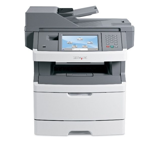
Lexmark X464de
Рейтинг
Модули
Electronics
Options and Power cords
Tray assemblies
Imaging
COVERS
FRAME
Детали Options and Power cords
Деталь: | LSU hsync extension cable |
Парткод: | 40X5816 |
Деталь: | Stairway cable |
Парткод: | 40X5832 |
Деталь: | Controller board cable |
Парткод: | 40X5833 |
Деталь: | Fuser assembly, 115 V |
Парткод: | 40X5344 |

Деталь: | Fuser assembly, 230 V |
Парткод: | 40X5345 |
Цена: | 16 200 ₽ |
Деталь: | Fuser assembly, 100 V |
Парткод: | 40X5346 |
Деталь: | Duplex and media sensor assembly |
Парткод: | 40X5365 |
Деталь: | Access door open sensor assembly |
Парткод: | 40X5360 |
Деталь: | Cooling fan (screws included) |
Парткод: | 40X5392 |
Деталь: | Engine board, |
Парткод: | 40X5830 |
Деталь: | Toner low sensor |
Парткод: | 40X5385 |
Деталь: | LVPS/HVPS card assembly, 110 V |
Парткод: | 40X5842 |
Деталь: | LVPS/HVPS card assembly, 220 V |
Парткод: | 40X5841 |
Деталь: | Manual input sensor assembly |
Парткод: | 40X5366 |
Деталь: | Manual feed solenoid |
Парткод: | 40X5369 |
Деталь: | MPF feed clutch |
Парткод: | 40X5371 |
Деталь: | Lower card reader cover |
Парткод: | 40X1476 |

Деталь: | Media feed (ACM) clutch |
Парткод: | 40X5370 |
Цена: | 1 000 ₽ |
Деталь: | Upper card reader cover |
Парткод: | 40X1478 |
Деталь: | Card reader light pipe |
Парткод: | 40X1477 |
Деталь: | LSU, (printhead) |
Парткод: | 40X5387 |
Деталь: | Card reader assembly (3121 contact) |
Парткод: | 40X4602 |
Деталь: | Card reader assembly (5121 contact/RFID) |
Парткод: | 40X4603 |
Деталь: | Card reader assembly (5125 contact/RFID |
Парткод: | 40X4604 |
Деталь: | Card reader cable |
Парткод: | 40X1475 |
Деталь: | Controller board fan |
Парткод: | 40X5805 |
Деталь: | Screw kit (for card reader) |
Парткод: | 40X1479 |
Деталь: | LSU laser diode cable |
Парткод: | 40X5817 |
Деталь: | Controller board |
Парткод: | 40X5829 |
Деталь: | Japanese font card assembly |
Парткод: | 40X5972 |
Деталь: | Simplified Chinese font card assembly |
Парткод: | 40X5970 |
Деталь: | Traditional Chinese font card assembly |
Парткод: | 40X5971 |
Деталь: | Korean font card assembly |
Парткод: | 40X5969 |
Деталь: | Print cryption card assembly |
Парткод: | 40X5952 |
Деталь: | Bar code and forms |
Парткод: | 40X0055 |
Деталь: | 128MB DIMM |
Парткод: | 40X5937 |
Деталь: | 256MB DIMM |
Парткод: | 40X5938 |
Деталь: | 512MB DIMM |
Парткод: | 40X5939 |
Деталь: | 256MB flash |
Парткод: | 40X5704 |
Деталь: | Parallel cable, packaged (3 m) |
Парткод: | 40X1367 |
Деталь: | USB cable, packaged (2 m) |
Парткод: | 40X1368 |
Деталь: | 80 GB Hard Disk Drive |
Парткод: | 40X4822 |
Деталь: | 80 GB Hard Disk Drive TAA |
Парткод: | 40X5057 |
Деталь: | Wireless ISP Adapter (US) |
Парткод: | 40X5038 |
Деталь: | Wireless ISP Adapter (EMEA) |
Парткод: | 40X5039 |
Деталь: | Thumbscrews (for use with 40X5038, and 40X5309) |
Парткод: | 40X5318 |
Деталь: | N.8110 V.34 Fax |
Парткод: | 40X4821 |
Деталь: | 14 Pin JST for Fax Cable (Use with 40X4821) |
Парткод: | 40X5606 |
Деталь: | RJ11 Cable w/Toroids |
Парткод: | 56P0558 |
Деталь: | RS 232 Serial adapter |
Парткод: | 40X4819 |
Деталь: | N8120 Gigabit INA |
Парткод: | 40X4826 |
Деталь: | ISP screw (use with all option cards except 40X5308, and 40X5309) |
Парткод: | 40X5315 |
Деталь: | 14 Pin JST for ISP Cable (Use with all option cards except 40X4821) |
Парткод: | 40X5316 |
Деталь: | Standoff Tee w/thumbscrew |
Парткод: | 40X5317 |
Деталь: | Parallel 1284-B thick adapter |
Парткод: | 40X4823 |
Деталь: | N8130 10/100 Fiber adapter |
Парткод: | 40X4827 |
Деталь: | IPDS card (X466 only) |
Парткод: | 40X0108 |
Деталь: | Relocation Kit |
Парткод: | 7377732 |
Деталь: | Power cord, 1.8M (straight)USA, Canada |
Парткод: | 40X0297 |
Деталь: | Power cord, 6 foot (straight)Europe and others |
Парткод: | 40X0278 |
Деталь: | Power cord, 8 foot (straight)Argentina |
Парткод: | 40X0288 |
Деталь: | Power cord, 8 foot (straight)United Kingdom |
Парткод: | 40X0286 |
Деталь: | Power cord, 6 foot (straight)Israel |
Парткод: | 40X0275 |
Деталь: | Power cord, 6 foot (straight)Switzerland |
Парткод: | 40X0274 |
Деталь: | Power cord, 6 foot (straight)South Africa |
Парткод: | 40X0276 |
Деталь: | Power cord, 6 foot (straight)Traditional Italy |
Парткод: | 40X0287 |
Деталь: | Power cord, 6 foot (straight)Denmark |
Парткод: | 40X0279 |
Деталь: | Power cord, 8 foot (straight)Brazil |
Парткод: | 40X4596 |
Деталь: | Power cord, 1.8M (straight)PRC |
Парткод: | 40X0282 |
Деталь: | Power cord, 2.5M (straight)Japan |
Парткод: | 40X0270 |
Деталь: | Power cord, 1.8M (straight)Korea |
Парткод: | 40X0280 |
Деталь: | Power cord, 1.8M (straight)Taiwan |
Парткод: | 40X0281 |
Деталь: | Power cord, 1.8M (straight)Australia |
Парткод: | 40X0296 |
Деталь: | Optional 550-sheet tray (new asm) |
Парткод: | 40X5399 |
Деталь: | 250-sheet (Tray 2) assembly (new asm) |
Парткод: | 40X5394 |
Деталь: | 550-sheet (Tray 2) assembly (new asm) |
Парткод: | 40X5395 |
Деталь: | Tray 2 wear strips (550-sheet tray only) (new asm) |
Парткод: | 40X2855 |
Деталь: | Primary tray |
Парткод: | 40X5381 |
Деталь: | Wear strips (250-sheet trays, optional and primary) (new asm) |
Парткод: | 40X5382 |
Деталь: | Optional 250-sheet tray (new asm) |
Парткод: | 40X5398 |
Деталь: | ADF separator roll |
Парткод: | 40X5471 |
Деталь: | ADF separator pad |
Парткод: | 40X5472 |
Деталь: | ADF input tray |
Парткод: | 40X5470 |
Деталь: | ADF cable |
Парткод: | 40X5540 |
Деталь: | Duplex ADF unit |
Парткод: | 40X5824 |
Деталь: | Flatbed cushion |
Парткод: | 40X5804 |
Деталь: | Flatbed module |
Парткод: | 40X5825 |
Деталь: | Right scanner cover |
Парткод: | 40X5818 |
Деталь: | Operator panel button assembly |
Парткод: | 40X5836 |
Деталь: | UICC Cable (Operator panel cable) |
Парткод: | 40X5810 |
Деталь: | Operator panel USB cable |
Парткод: | 40X5831 |
Деталь: | Scanner front cover |
Парткод: | 40X5826 |
Деталь: | Op panel display |
Парткод: | 40X5837 |
Деталь: | Op panel display bezel X463 |
Парткод: | 40X0399 |
Деталь: | Op panel display bezel X464 |
Парткод: | 40X0400 |
Деталь: | Op panel display bezel X466 |
Парткод: | 40X0401 |
Деталь: | Kickstand support |
Парткод: | 40X5813 |
Деталь: | Left scanner cover |
Парткод: | 40X5819 |
Деталь: | ADF MAINTENANCE KIT |
Парткод: | 40X5807 |
Деталь: | Rear door |
Парткод: | 40X5839 |
Деталь: | REAR COVER |
Парткод: | 40X5838 |
Деталь: | Rear left frame assembly |
Парткод: | 40X5820 |
Деталь: | Rear right frame assembly |
Парткод: | 40X5821 |
Деталь: | RIGHT SIDE COVER |
Парткод: | 40X5822 |
Деталь: | Front door cover |
Парткод: | 40X5379 |
Деталь: | Nameplate cover |
Парткод: | 40X5359 |
Деталь: | Lower AIO access assembly |
Парткод: | 40X5806 |
Деталь: | Front access door cover |
Парткод: | 40X5778 |
Деталь: | LEFT SIDE COVER |
Парткод: | 40X5823 |
Деталь: | TOP COVER ASSEMBLY |
Парткод: | 40X5614 |
Деталь: | Tub cover assembly |
Парткод: | 40X5811 |
Деталь: | USB cable mount bracket |
Парткод: | 40X5809 |
Деталь: | Output bin LED lens |
Парткод: | 40X5834 |
Деталь: | Output bin LED |
Парткод: | 40X5835 |
Деталь: | Op panel support |
Парткод: | 40X5815 |
Деталь: | Display rotation support |
Парткод: | 40X5814 |
Деталь: | Primary tray |
Парткод: | 40X5381 |
Деталь: | Mid rear cover |
Парткод: | 40X5827 |
Деталь: | Media exit guide assembly (redrive) |
Парткод: | 40X5372 |
Деталь: | Front mounts |
Парткод: | 40X5397 |
Деталь: | Screws, miscellaneous |
Парткод: | 40X5396 |
Деталь: | Complete duplex assembly |
Парткод: | 40X5380 |

Деталь: | Media (ACM) drive assembly |
Парткод: | 40X5453 |
Цена: | 2 000 ₽ |

Деталь: | Paper feed, ACM tires |
Парткод: | 40X5451 |
Цена: | 500 ₽ |
Деталь: | Tray 2 paper feed tires |
Парткод: | 40X5440 |
Деталь: | MPF tray assembly |
Парткод: | 40X5358 |
Деталь: | Upper front frame assembly |
Парткод: | 40X5383 |
Деталь: | Manual feed clutch CBM |
Парткод: | 40X5368 |
Деталь: | Main drive gearbox (in motor) |
Парткод: | 40X5367 |
Деталь: | Duplex gear drive CBM |
Парткод: | 40X5363 |

Деталь: | Transfer roll, bearings, gear, spring (CBM) |
Парткод: | 40X5364 |
Цена: | 1 500 ₽ |
Деталь: | 110 V maintenance kit |
Парткод: | 40X5400 |
Деталь: | 220 V Maintenance kit |
Парткод: | 40X5401 |
Деталь: | 100 V maintenance kit |
Парткод: | 40X5402 |
Деталь: | Field relocation package assembly |
Парткод: | 7377732 |
Коды ошибок
200.00
200.01
200.02
200.03
200.04
200.06
200.08
200.09
200.12
200.13
200.14
200.15
200.16, 200.17
200.18
200.19
200.20
200.22
200.23
200.24
200.26
200.27
200.28
200.29
200.30
200.32
200.33
200.34
200.35...200.38
200.42
200.43
201.00
201.01
201.02
201.03
201.05
201.25, 201.26, 201.27
202.00
202.01...202.25
202.26
202.32
231.00...234.01
235.01
241.00...241.19
242.00
242.01
242.08
242.10
242.12
242.16
251.00...251.19
251.20, 251.21
290.02...291.00
292.00, 293.02
294.04, 294.05, 294.06
34
35
37
38
39
50
51
52
53
54
56
58
84
840.01, 840.02
841.00...842.00
843.00
843.01
843.02...846.07
847.00...849.01
88
902.xx...906.xx
910.xx...914.01
917.xx
920.00...925.xx
927.00
929.00...929.03
930.xx...935.xx
936.xx...937.00
940.00
948.xx, 949.xx
950.xx
951.xx
952.xx
953.xx
954.xx
955.xx
956.00
956.01
957.xx
958.xx
959.01, 959.02
959.03...959.05
959.20...960.xx
961.xx
964.xx
975.xx...991.xx
Описание
Error code: | 200.00 |
Description: | Paper jam Check area A Sensor (registration) off jam (too long) The sensor (registration) is not turned off within the specified time after the registration clutch is turned on. |
Remedy: | 1 Check the media position. Open the printer left door assembly, and visually check it. Does the media touch the sensor (registration)? Remove the media. Go to step 2. 2 Check the roll. Open the printer left door assembly, and check it. Is the transport roll assembly free of excess wear and contamination? Go to step 3. Clean or replace the transport roll assembly. Go to “Transfer roll assembly removal”. 3 Check the sensor (registration) for proper operation. 1. Enter the Diagnostics Menu. 2. Touch BASE SENSOR TEST. 3. Touch Media Path. 4. Touch Registration. Open the printer left door assembly, and check it. Does the display on the operator panel change every time the sensor actuator is operated? Go to step 5. Go to step 4. 4 Check the sensor (registration) connection. Is the sensor (registration) properly connected? Replace the sensor (registration). Go to “Sensor (registration) removal”. Replace the connection. 5 Check the registration clutch for proper operation. 1. Enter the Diagnostics Menu. 2. Touch MOTOR TESTS. 3. Touch Printer Motor Test. 4. Touch Registrat clutch. Does the registration clutch make an audible clicking sound when activated? Go to step 7. Go to step 6. 6 Check the registration clutch connection. Is the registration clutch properly connected? Replace the registration clutch. Go to “Registration clutch assembly removal”. Replace the connection. 7 Perform a print test. Does the error continue? Replace the printer engine card assembly. Go to “Printer engine card assembly removal”. Problem solved. |
Error code: | 200.01 |
Display: | 200.01 |
Description: | Input sensor is made when printer tries to print from an idle state. Possible causes: • Paper jam leaving page over sensor • Defective input sensor • Faulty system card |
Remedy: | • Check for anything in the paper path that might cause the paper to jam. |
Error code: | 200.02 |
Description: | The main input sensor never became uncovered from the printer and the driver. the sheet ahead. |
Remedy: | First, remove the PC kit and paper or debris at the input sensor. Then, inspect the flag on the input sensor. It should rotate freely. Replace the sensor if necessary. Finally, check the paper size settings in the printer and the driver. |
Error code: | 200.03 |
Description: | Media is late reaching the sensor (input) within the specified time. |
Remedy: | Step 1 Check the media size setup and tray guides for all media trays. Does the media size, in use, match the size set for all media trays? Go to step 2. Replace the media, or change the media size setup. Step 2 Check the media trays for overfilling. Are any of the media trays overfilled? Remove any excess new media. Go to step 3. Step 3 Check the media condition in all media trays. Is any of the media in any of the media trays crumpled or damaged? Replace the damaged media. Go to step 4. Step 4 Check media origination. Did the media originate from the MPF? Go to step 5. Go to step 7. Step 5 Check the MPF pick roll assembly. Is the above component free of excess wear and contamination? Go to step 6. Clean or replace the MPF pick roller. See “MPF pick roller removal”. Step 6 Perform a MPF print test, and check the MPF pick solenoid for proper operation. Does the above component operate properly? Go to step 9. Replace the MPF pick solenoid. Step 7 Check the pick roller assembly in the media tray being picked from. Is the pick roller assembly free of excess wear and contamination? Go to step 8. Clean or replace the pick roller assembly. See “Pick roller assembly removal”. Step 8 Check the pick roller assembly for proper installation. Fully press the pick roller assembly toward the sensor to make sure the mounting latches are properly engaging the slot in the shaft. Does the problem remain? Go to step 9. The problem is solved. Step 9 Check the aligner assembly for obstructions. Is the above component free from obstructions? Go to step 10. Remove obstructions. |
Error code: | 200.04 |
Description: | Input sensor covered too quickly • Paper pre-staged in paper path. • Wrong configuration ID causes engine to assume 500-sheet paper path on 250-sheet model. • Bouncy input sensor. |
Remedy: | • Check MPF and friction pad. • Fan media and stack flat in tray or MPF. • Use different media. • Check config ID. |
Error code: | 200.06 |
Description: | Imaged page not expected page. Bouncy pass thru sensor. |
Remedy: | This test is used to determine if the input tray sensors are working correctly. To run the Input Tray Sensor Test: 1. Touch to select the Sensor Test from INPUT TRAY TESTS. 2. Touch to select the input source from the sources displayed on the Sensor Test menu. All installed sources are listed. 3. Select the sensor to test. Various sources have different combinations of sensors. [sensor selected]=Open displays. • Empty—Input tray empty sensor • Low—Input tray paper low sensor • passThru—Input tray pass thru sensor 4. Once this message displays, the servicer can manually actuate each sensor. The tray empty sensor can be actuated by hand, however a sheet of paper can be used to cover the pass thru sensor. When the sensor is closed, Closed displays; when the sensor is open, Open displays. 5. Press Stop ( ) to exit the test. |
Error code: | 200.08 |
Description: | Media is late reaching the sensor (input) within the specified time. |
Remedy: | Step 1 Check the media size setup and tray guides for all media trays. Does the media size, in use, match the size set for all media trays? Go to step 2. Replace the media, or change the media size setup. Step 2 Check the media trays for overfilling. Are any of the media trays overfilled? Remove any excess new media. Go to step 3. Step 3 Check the media condition in all media trays. Is any of the media in any of the media trays crumpled or damaged? Replace the damaged media. Go to step 4. Step 4 Check media origination. Did the media originate from the MPF? Go to step 5. Go to step 7. Step 5 Check the MPF pick roll assembly. Is the above component free of excess wear and contamination? Go to step 6. Clean or replace the MPF pick roller. See “MPF pick roller removal”. Step 6 Perform a MPF print test, and check the MPF pick solenoid for proper operation. Does the above component operate properly? Go to step 9. Replace the MPF pick solenoid. Step 7 Check the pick roller assembly in the media tray being picked from. Is the pick roller assembly free of excess wear and contamination? Go to step 8. Clean or replace the pick roller assembly. See “Pick roller assembly removal”. Step 8 Check the pick roller assembly for proper installation. Fully press the pick roller assembly toward the sensor to make sure the mounting latches are properly engaging the slot in the shaft. Does the problem remain? Go to step 9. The problem is solved. Step 9 Check the aligner assembly for obstructions. Is the above component free from obstructions? Go to step 10. Remove obstructions. |
Error code: | 200.09 |
Description: | Did not receive proper motor feedback to start laser servo. Motor connections |
Remedy: | 1 Main drive assembly (excessive noise or vibration) Remove the controller board and run a Diagnostic Print Test in the continuous mode. Check the main drive assembly for any excessive noise or vibration. Determine if the noise is in the main drive, toner cartridge, fuser, or main drive gearbox. Look for any loose or worn parts in the developer drive assembly, main drive gearbox, or fuser. Repair as necessary. 2 Main drive motor assembly (excessive noise, gears ratcheting and so on) A service error code 936 - Transport Motor may be displayed. Check the voltage at J20-6 on the system board. It measures approximately +5 V dc when the motor is not running and goes to 0 V dc when the motor is running. If incorrect, replace the system board. If this does not fix the problem, replace the main drive motor. 3 Main drive motor cable Check the continuity of the main drive motor cable. If incorrect, replace the cable. 4 Motor gear does not turn, no 936 error code or 201.xx Paper Jam user message displays. Check the voltages at J20 on the system board. J20-11 +24 V dc J20-8 +5 V dc 0 V dc J20-7 +5 V dc 0 V dc J20-6 +5 V dc +2.5 V dc J20-5 +5 V dc 0 V dc J20-4 +5 V dc +5 V dc J20-1 +5 V dc 0 V dc If the voltage is incorrect, replace the FRUs in the following order: • Main drive motor assembly • System board |
Error code: | 200.12 |
Description: | Media detected at manual feeder sensor when not expected. Possible causes include user insert of media when motor is running or pre-staged media in the tray. |
Remedy: | Carefully remove the tray and notice if the leading edge of the media is pointed upward and out of the tray. If so, then inspect the tray wear strips and replace if necessary. Inspect the input sensor flag and replace it if it does not rotate freely or is too loose. |
Error code: | 200.13 |
Description: | The page at the sensor (input) is not the next page to be imaged. |
Remedy: | Step 1 Check the appropriate media tray sensor (pass through) in the appropriate input option for proper operation. a Enter the diagnostic mode. b Select Input tray tests. c Select Sensor test. d Select the appropriate input tray. Observe the line item “pass through” for the appropriate media tray. Does the display on the control panel change every time the sensing area of the above sensor is interrupted or blocked? Go to step 3. Go to step 2. S tep 2 Check the above sensor for proper connection. Is the above sensor connected properly? Replace the sensor (pass through). See “Sensor (drawer pass through) removal ”. Reseat the connection. Step 3 Perform a print test using the appropriate input tray. Does the error continue? Replace the input option. Problem solved. 7463 Diagnostic information 64 |
Error code: | 200.14 |
Description: | Proper main motor feedback to start laser servo was not received. |
Remedy: | Step 1 Ensure the cables for sockets “MIR MTR” and “VIDEO” on the controller card are properly connected and not damaged. Are the cables connected and undamaged? Go to step 2. Reseat the connections. Go to step 2. Step 2 Reset the machine. Does the error continue? Replace the printhead. See “Laser printhead removal”. Problem solved. Step 3 Reset the machine. Does the error continue? Replace the controller board. See “Controller board removal”. Problem solved. |
Error code: | 200.15 |
Description: | Media reached the sensor (input) but did not clear it within the specified time. (Media source = Tray 1) |
Remedy: | Step 1 Check the media size setup and tray guides for all media trays. Does the media size, in use, match the size set for all media trays? Go to step 2. Replace the media, or change the media size setup. Step 2 Check the media trays for overfilling. Are any of the media trays overfilled? Remove any excess new media. Go to step 3. Step 3 Check the media condition in all media trays. Is any of the media in any of the media trays crumpled or damaged? Replace the damaged media. Go to step 4. |
Error code: | 200.16, 200.17 |
Description: | 200.16 Transport motor error detected 200.17 Took too long to ramp up transport motor |
Remedy: | Main motor gear drive Main motor cable LVPS/HVPS Controller board Warning: Do not replace the operator panel and controller board at the same time. Each card contains the printer settings. When either of these cards is new, it obtains the settings from the other card. Settings are lost when both are new and replaced at the same time. Turn off the printer, and unplug the main motor cable at J19. Turn on the printer, and check for the following voltages at J19: Verify ground at pin 5 for both the card and cable. •If these voltages are correct, then check the main motor cable for continuity. - Remove the left side cover to access the connector on the motor. - If continuity exists on each wire, then replace the main motor gear drive which includes the motor. - If continuity does not exist on one or more of the wires, then call the next level of support. •If these voltages are not correct, then see “Controller board connector pin values”, or replace the controller board. See “Controller board removal”. |
Error code: | 200.18 |
Description: | Manual feeder sensor never became uncovered from the sheet ahead. |
Remedy: | Remove the toner cartridge/PC kit. At the front, remove the upper front guide, and inspect the flag on the manual input sensor. If the flag is loose, then replace it. See “Media manual input sensor removal”. |
Error code: | 200.19 |
Description: | The media never reached the input sensor, but was detected at manual feeder sensor. |
Remedy: | Remove the toner cartridge/PC kit, and inspect for debris in the paper path. Check the bottom of the PC kit for any obstructions. Remove the upper front guide, and inspect the pinch rollers. |
Error code: | 200.20 |
Description: | The media is too long over the manual feeder sensor. Possible causes include multi-sheet feed, media size (length) problem, pre-staged media in the tray. |
Remedy: | Verify that the media is approved. Inspect the wear strips in the tray, and replace if they are worn. |
Error code: | 200.22 |
Display: | 200.22 |
Description: | Pick (tray 1) motor stalled. Possible causes: • Faulty cable/connector • Faulty pick motor • Faulty system card |
Remedy: | • Check for anything in the paper path that might cause the paper to jam. |
Error code: | 200.23 |
Description: | 200.23 Paper fed from tray 2 jammed at the sensor (input). Paper did not reach the sensor (input). |
Remedy: | Step 1 Check the tray 1 paper path. Is the paper path free of fragments and contamination? Go to step 3. Go to step 2. Step 2 Clean the paper path. Does the problem remain? Go to step 3. The problem is solved. Step 3 Check tray 2 for overfilling. Is the tray overfilled? Go to step 4. Go to step 5. Step 4 Remove the excess paper from the tray. Does the problem remain? Go to step 5. The problem is solved. Step 5 Check the paper condition in tray 2. Is the paper crumpled or damaged? Go to step 6. Go to step 7. Step 6 Replace the crumpled or damaged paper. Does the problem remain? Go to step 7. The problem is solved. Step 7 Check the tray 2 separator pad for misalignment and damage. Is the separator pad properly installed and free of damage? Go to step 9. Go to step 8. Step 8 Reinstall or replace the separator pad. See “Separator pad removal”. Does the problem remain? Go to step 9. The problem is solved. Step 9 Check the condition of the tray 2 pick roller. Is the pick roller free from excess wear, contamination, and damage? Go to step 11. Go to step 10. Step 10 Replace the pick roller. See “Pick roller removal”. Does the problem remain? Go to step 11. The problem is solved. Step 11 a Check the pick roller for proper installation. b Fully press the pick roller assembly upward to make sure the mounting latches are properly engaging the slot on the shaft. Is the pick roller assembly properly installed? Go to step 13. Go to step 12. Step 12 Reinstall the pick roller assembly. Does the problem remain? Go to step 13. The problem is solved. Step 13 Check the paper path along the tray 2 exit. Is the paper path free of fragments and contamination? Go to step 15. Go to step 14. Step 14 Clean the paper path. Does the problem remain? Go to step 15. The problem is solved. Step 15 a Enter the Diagnostics menu, and then navigate to: Printer diagnostics & adjustments > Sensor tests b Find the sensor (Input). Does the sensor status change while toggling the sensor? Go to step 18. Go to step 16. Step 16 Check the sensor cable for proper connection, and then reseat if necessary. Does the problem remain? Go to step 17. The problem is solved. Step 17 Replace the sensor. See “Sensor (input) removal”. Does the problem remain? Go to step 18. The problem is solved. Step 18 a Enter the Diagnostics menu, and then navigate to: Printer diagnostics & adjustments > Sensor tests b Find the sensor (MPF/pass-through). Does the sensor status change while toggling the sensor? Go to step 21. Go to step 19. Step 19 Check the sensor cable for proper connection, and then reseat if necessary. Does the problem remain? Go to step 20. The problem is solved. Step 20 Replace the sensor. See “Sensor (MPF/pass-through) with deflector removal”. Does the problem remain? Go to step 21. The problem is solved. Step 21 a Enter the Diagnostics menu, and then navigate to: Printer diagnostics & adjustments > Motor tests > Isolation b Touch Start. Does the motor run? Go to step 24. Go to step 22. Step 22 Check the motor cable for proper connection, and then reseat if necessary. Does the problem remain? Go to step 23. The problem is solved. Step 23 Replace the motor (isolation). Does the problem remain? Go to step 24. The problem is solved. Step 24 Perform a print job. Does the problem remain? Contact the next level of support. The problem is solved. |
Error code: | 200.24 |
Description: | The measured gap at the input sensor is too small to meet the video delivery requirements. (There is not enough time since prior image finished to start new image) |
Remedy: | Verify that the media is approved. Inspect the wear strips in the tray, and replace if they are worn. |
Error code: | 200.26 |
Description: | The trailing edge never cleared the input sensor when feeding out the media that was detected during warmup. |
Remedy: | Verify that the media is approved. Inspect the wear strips in the tray, and replace if they are worn. |
Error code: | 200.27 |
Description: | Printhead Driver: Mirror motor fell out of lock condition after the media at the input sensor–more time elapsed since the printhead than the expected stable lock time, but less than the printhead jitter-stable specification. Mirror motor fell out of lock condition after media at the input sensor–more time elapsed since the printhead than expected stable lock time, but less than the printhead jitter-stable specification. |
Remedy: | Printhead Note: New printhead must be aligned. See “Printhead assembly electronic adjustment”. Turn the printer off. Disconnect the printhead cables from J12 and J8 on the controller board. Turn the printer on with the front door closed. On the controller board, verify +5 V dc on pin 10 at J12 and +5 V dc on pins 1, 2, and 3 at J8. Verify grounds on pins 2, 4, and 7 at J12 and on pin 4 at J8. •If voltages or grounds are incorrect, then check the controller board. See “Controller board service check” for more information. •If voltages are correct, then replace the printhead (comes with cables). |
Error code: | 200.28 |
Description: | First writing line of a page at the developer nip, but laser servo cleanup is not complete. Likely pre staged media or a fast paper feed. |
Remedy: | Verify that the media is approved. Inspect the wear strips in the tray, and replace if they are worn. |
Error code: | 200.29 |
Description: | Printhead drive control out of range due to an external event beyond what the control is designed to handle. Probable causes: ESD or noise on hsync signal. |
Remedy: | Check the cable routing for the printhead. See “Printhead service check”. |
Error code: | 200.30 |
Description: | Narrow media sensor covered during warm-up. |
Remedy: | Check that the narrow media flag rotates freely and securely. If it is dislodged or broken, then replace the rear exit guide. See “Rear exit guide assembly with sensor and reversing solenoid removal”. |
Error code: | 200.32 |
Description: | Detected sensor (control panel interlock) bounce. |
Remedy: | Step 1 Check the sensor (input) for proper operation. a Enter the diagnostic mode. b Select Base sensor test. c Observe the line item control panel door interlock. Does the display on the control panel change every time the sensing area of the above sensor is interrupted or blocked? Go to step 3. Go to step 2. Step 2 Check the above sensor for proper connection. Is the above sensor connected properly? Replace the sensor (control panel door interlock). Go to step 3. Replace the connection. Go to step 3. Step 3 Reset the machine. Does the error continue? Replace the controller board. See “Controller board removal”. Problem solved. |
Error code: | 200.33 |
Description: | Printhead was not ready for page when sensor (input) was reached. |
Remedy: | Step 1 Ensure the cables for sockets “MIR MTR” and “VIDEO” on the controller card are properly connected and not damaged. Are the cables connected and undamaged? Go to step 2. Reseat the connections. Go to step 2. Step 2 Reset the machine. Does the error continue? Replace the printhead. See “Laser printhead removal”. Problem solved. Step 3 Reset the machine. Does the error continue? Replace the controller board. See “Controller board removal”. Problem solved. |
Error code: | 200.34 |
Description: | Short media detected. |
Remedy: | Step 1 Check the sensor (input) for proper operation. a Enter the diagnostic mode. b Select Base sensor test. c Observe the line item control panel door interlock. Does the display on the control panel change every time the sensing area of the above sensor is interrupted or blocked? Go to step 3. Go to step 2. Step 2 Check the above sensor for proper connection. Is the above sensor connected properly? Replace the sensor (control panel door interlock). Go to step 3. Replace the connection. Go to step 3. Step 3 Reset the machine. Does the error continue? Replace the controller board. See “Controller board removal”. Problem solved. |
Error code: | 200.35...200.38 |
Description: | 200.35 Failed to create hsync during auto alignment 200.36 Lost hsyncs during auto alignment 200.37 Timeout on data collection during auto alignment 200.38 Interpage servo gap is smaller than expected for printhead offset target evaluation |
Remedy: | Printhead Note: New printhead must be aligned. See “Printhead assembly electronic adjustment”. Turn the printer off. Disconnect the printhead cables from J12 and J8 on the controller board. Turn the printer on with the front door closed. On the controller board, verify +5 V dc on pin 10 at J12 and +5 V dc on pins 1, 2, and 3 at J8. Verify grounds on pins 2, 4, and 7 at J12 and on pin 4 at J8. •If voltages or grounds are incorrect, then check the controller board. See “Controller board service check” for more information. •If voltages are correct, then replace the printhead (comes with cables). |
Error code: | 200.42 |
Description: | Rogue sheet is at the manual feed sensor while flushing the paper path prior to declaring MPF source empty. |
Remedy: | Retry alignment. |
Error code: | 200.43 |
Description: | The media is at the input sensor before interruption occurs. Possible causes include bouncy sensor or an exceptionally small gap, perhaps due to the media being pre-staged in the source tray. |
Remedy: | Remove the media, realign the stock, and re-insert. Do not let the top sheets to go beyond the wear strips. |
Error code: | 201.00 |
Description: | Paper jam Check area A Sensor (fuser exit) on jam The sensor (fuser exit) is not turned on within the specified time after the registration clutch is turned on. |
Remedy: | 1 Check the media position. Does the media touch the sensor (fuser exit)? Open the printer left door assembly, and visually check it. Remove the media. Go to step 2. 2 Check the fuser exit actuator. Does the fuser exit actuator appear to be binding or sticking in its normal resting position and not allowing media to pass? Replace the fuser exit actuator. Go to “Sensor (fuser exit) removal”. Go to step 3. 3 Check the roll. Open the printer left door assembly, and check it. Is the transfer roll assembly free of excess wear and contamination? Go to step 4. Clean or replace the transfer roll assembly. Go to“Transfer roll assembly removal”. 4 Inspect the pinch roll on the transfer roll guide assembly. Is the transfer roll guide assembly free of damage? Go to step 5 Replace the transfer roll guide assembly Go to “Transfer roll guide assembly removal”. 5 Check the sensor (fuser exit) for proper operation. 1. Enter the Diagnostics Menu. 2. Touch BASE SENSOR TEST. 3. Touch Media Path. 4. Touch Fuser exit. Open the printer left door assembly, and check it. The area around the actuator is very hot. Allow the fuser area to cool before proceeding. Does the display on the operator panel change every time the sensor actuator is operated? Go to step 7. Go to step 6. 6 Check the sensor (fuser exit) connection. Is the sensor (fuser exit) properly connected? Replace the sensor (fuser exit). Go to “Sensor (fuser exit) removal”. Replace the connection. 7 Check the registration clutch for proper operation. 1. Enter the Diagnostics Menu. 2. Touch MOTOR TESTS. 3. Touch Printer Motor Test. 4. Touch Registrat clutch. Does the registration clutch make an audible clicking sound when activated? Go to step 8. Go to step 9 8 Check the registration clutch connection. Is the registration clutch properly connected? Replace the registration clutch. Go to “Registration clutch assembly removal”. Replace the connection. 9 Perform a print test. Does the error continue? Replace the printer engine card assembly. Go to “Printer engine card assembly removal”. Problem solved. |
Error code: | 201.01 |
Description: | Narrow media sensor is covered during warm up. Input sensor is not covered. |
Remedy: | Step 1 Check the narrow media sensor cable JNRW1 for proper connection. Is it properly connected? Go to step 2. Reseat the cable. Step 2 POR into the Diagnostics menu and perform a sensor test: Diagnostics Menu > Base Sensor Test > Narrow Media Does the sensor state on the control panel display change when it is toggled? Go to step 3. Replace the narrow media sensor. See “Narrow media/bin full sensor removal”. Step 3 Check the redrive rollers for damage. Are they free of damage? Go to step 4. Replace the redrive assembly. See “Redrive assembly removal”. Step 4 Does the error remain? Contact the next level of support. The problem is solved. |
Error code: | 201.02 |
Description: | Exit sensor never made by leading edge of page. Also known as internal jam. |
Remedy: | Remove the PC kit and paper or debris at the input sensor. |
Error code: | 201.03 |
Description: | Video never started on the page at the input sensor within two inches after hitting the input sensor |
Remedy: | Check the printhead. |
Error code: | 201.05 |
Description: | Restart attempted after an internal jam without the cover open/close event. It is likely that the jam was never cleared. |
Remedy: | Check the paper path and remove any media in the path. |
Error code: | 201.25, 201.26, 201.27 |
Description: | 201.25 Exit sensor never made by leading edge of media when feeding out the media that was detected during warm-up. 201.26 Page at fuser nip before fuser started ramping toward desired temperature. Indicates code may be receiving more interrupts than intended 201.27 Page at fuser nip before fuser reached acceptable operating temperature. Page arrived at fuser earlier than expected, so it was probably staged prematurely. |
Remedy: | Remove the toner cartridge/PC kit and check for obstructions between the input sensor and the fuser. if the media continues to stop at the entrance or in the fuser, then replace the fuser |
Error code: | 202.00 |
Description: | Paper jam Check area A Sensor (fuser exit) off jam The sensor (fuser exit) is not turned off within the specified time after the sensor (fuser exit) is turned on. |
Remedy: | 1 Check the media position. Open the printer left door assembly, and visually check it. Does the media touch the sensor (fuser exit)? Remove the media. Go to step 2. 2 Check the roll. Open the printer left door assembly, and check it. Is the transport roll assembly free of excess wear and contamination? Go to step 3. Clean or replace the transport roll assembly. 3 Check the sensor (fuser exit) for proper operation. 1. Enter the Diagnostics Menu. 2. Touch BASE SENSOR TEST. 3. Touch Media Path. 4. Touch Fuser exit. Open the printer left door assembly, and check it. The area around the actuator is very hot. Allow the fuser area to cool before proceeding. Does the display on the operator panel change every time the sensor actuator is operated? Go to step 5. Go to step 4. 4 Check the sensor (fuser exit) connection. Is the sensor (fuser exit) properly connected? Replace the sensor (fuser exit). Go to “Sensor (fuser exit) removal”. Replace the connection. 5 Perform a print test. Does the error continue? Replace the printer engine card assembly. Go to “Printer engine card assembly removal”. Problem solved. |
Error code: | 202.01...202.25 |
Description: | 202.01 Exit sensor never broke on the trailing edge of the sheet at the exit sensor. 202.02 Exit sensor never broke from sheet ahead of page heading toward the exit sensor. 202.06 Exit sensor bounced 202.13 Exit sensor covered, media not expected (media not in machine during warm-up) 202.25 Exit sensor never broke from the sheet ahead of the page heading toward the exit sensor when feeding out the media detected during warm-up. |
Remedy: | Open the rear door, and inspect the flag on the exit sensor. The flag is located behind the fuser exit rollers, about mid printer. If the flag does not rotate freely or has no spring action, then replace the fuser. |
Error code: | 202.26 |
Description: | Trailing edge never cleared exit sensor when feeding out media that was detected during warm-up. |
Remedy: | Open the rear door, and inspect the flag on the exit sensor. The flag is located behind the fuser exit rollers, about mid printer. If the flag does not rotate freely or has no spring action, then replace the fuser. See “Fuser removal”. |
Error code: | 202.32 |
Description: | The media reached the sensor (fuser exit) but did not clear it within the specified time |
Remedy: | Step 1 Check the rear door. Is the rear door free of damage and properly closed? Go to step 2. Close or replace the rear door. See “Rear door removal”. Step 2 Check the fuser unit assembly for damage and life expiration. Is the above component damaged or has it exceeded life? Replace the fuser. See “Fuser removal”. Go to step 3. Step 3 Check the sensor (fuser output) for proper operation. a Enter the diagnostic mode. b Select Base sensor tests. c Observe the line item fuser exit. Does the display on the control panel change every time the sensing area of the above sensor is interrupted or blocked? Go to step 5. Go to step 4. Step 4 Check the above sensor for proper connection. Is the above sensor connected properly? Replace the fuser. See “Fuser removal”. Reseat the connection. Step 5 Check the upper redrive for damage. Is the above component free from damage? Go to step 6. Replace the upper redrive. See “Upper redrive removal”. Step 6 Perform a print test, and check the upper redrive motor for proper operation. Does the above component operate properly? Go to step 7. Replace the upper redrive motor. See “Upper redrive motor removal”. Step 7 Perform a print test. Does the problem remain? Contact the next highest level of technical support. Problem solved. |
Error code: | 231.00...234.01 |
Description: | 231.00 Duplex jam while reversing into the device 231.01 Duplex sensor never made by leading edge reversing into the duplex. 231.02 Bouncy duplex sensor never made. 232.00 Duplex jam while staging in the device 232.01 Duplex sensor never broke by the sheet ahead after reversing into the duplex. 232.02 Page in duplex ahead of current reversing page never staged. 233.00 Duplex jam while picking from the device 233.01 Page in duplex never picked. 233.02 Feed error picking from the duplex. 233.03 Paper never reached the input sensor, but was detected at the manual feed sensor. 234.01 Duplex sensor covered during warm-up. |
Remedy: | Open the rear cover and look for obstructions between the rear cover ribs, the fuser exit rollers, and below. The media entering the duplex passes outside the exit roller while the media exiting the fuser passes above and inside the exit rollers. Remove the tray, open the duplex door, and remove the obstructions. If there are no obstructions and the problem persists, then disconnect all of the cables, tilt the printer onto its back (be sure to protect the antenna on a wireless unit), and inspect the flag of the duplex sensor. If the flag does not rotate freely, then replace the paper input and duplex sensor. See “Paper input and duplex sensor assembly removal”. Check the belt and drive of the duplex unit. Replace it if necessary. |
Error code: | 235.01 |
Description: | Invalid duplex media |
Remedy: | Check the media. Duplex supports A4, letter, legal, oficio, and folio media sizes. |
Error code: | 241.00...241.19 |
Description: | 241.00 Paper jam near tray 1. 241.10 Second pick attempt failed from Tray 1 241.12 Second pick from manual feeder, tray 1, or feeder failed when the media was in the source while other sheets were committed to the paper path. 241.16 Failed to feed from tray 1. Pages in the paper path have been flushed to the output bin. 241.17 MISIDENTIFIED SMALL GAP JAM. Engine detected small gap at the manual feeder sensor, attempted to open the gap by stopping the feed rolls, trailing edge was seen at the input sensor, manual feeder sensor is no longer covered. 241.19 Second pick attempted failed from Tray 1, no pages printed since calling a 241.10 or a prior 241.19. |
Remedy: | Remove the tray and inspect the media path for obstructions. Check the pick rollers. Replace the pick rollers if they are worn or clogged with dust. See “ACM pick tire roller removal”. Also check the wear strips and the manual feeder, and replace if necessary. |
Error code: | 242.00 |
Description: | Paper jam Check area tray 2 Sensor (pre-feed) on jam (tray 2 feed) The sensor (pre-feed) tray 2 is not turned on within the specified time after the tray 2 media feed lift motor is turned on. |
Remedy: | 1 Check the media condition. Is the media in the tray crumpled or damaged? Replace the media with new media; ensure it is dry. Go to step 2. 2 Check the media size setup. Does the media size in use match the size set for tray 2? Go to step 3. Replace the media, or change the media size setup. 3 Check the rolls for tray 2. Remove tray 2 and check it. Are the feed roll, separation roll, and pick roll free of excess wear and contamination? Go to step 4. Clean or replace the feed roll, separation roll, and pick roll. Go to “Feed roll removal”, “Separation roll removal”, and “Pick roll removal”. 4 Check the media position. Open the printer left lower door assembly, and visually check it. Does the media touch the sensor (pre-feed) in the tray 2 media feed unit? Remove the media. Go to step 5. 5 Check the sensor (pre-feed) in tray 2 for proper operation. 1. Enter the Diagnostics Menu. 2. Touch INPUT TRAY TESTS. 3. Touch Sensor test. 4. Touch Tray 2. 5. Touch Pre-feed. Remove the media tray assembly, and check it. Does the display on the operator panel change every time a white piece of paper is placed over the sensing area? Ensure the media feed unit front guide is installed properly. Go to step 7. Go to step 6. 6 Check the sensor (pre-feed) connection. Is the sensor (pre-feed) properly connected? Replace the sensor (pre-feed). Go to “Sensor (pre-feed) removal”. Replace the connection. Go to “Sensor (pre-feed) removal”. 7 Check the media feed lift motor in tray 2 for proper operation. 1. Enter the Diagnostics Menu. 2. Touch MOTOR TESTS. 3. Touch Printer Motor Test. 4. Touch Tray 2 feed mtr. Pull out the tray 2, and check it. Does the media feed lift motor rotate normally. Go to step 10. Go to step 8. 8 Check the media feed lift motor connection. Is the media feed lift motor properly connected? Go to step 9. Replace the connection. Go to “Sensor (pre-feed) removal” 9 Check the media feed lift motor in tray 2 for proper operation. Replace the media feed lift motor for tray 2 with the one from tray 1. 1. Enter the Diagnostics Menu. 2. Touch MOTOR TESTS. 3. Touch Printer Motor Test. 4. Touch Tray 2 feed mtr. Does the media feed lift motor rotate normally? Install the media feed lift motor for tray 1 as it previously was, and replace the motor for tray 2 with a new motor. Go to “Media feed lift motor removal”. Go to step 10. 10 Perform a print test. Does the error continue? Replace the printer engine card assembly. Go to “Printer engine card assembly removal”. Problem solved. |
Error code: | 242.01 |
Description: | Paper jam Check area B, tray 2 Sensor (tray 2 feed-out) on jam (tray 2 feed) The sensor (tray 2 feed-out) is not turned on within the specified time after the sensor (pre-feed) media feed unit 2 is turned on. |
Remedy: | 1 Check the media condition. Is the media in the tray crumpled or damaged? Replace the media with new media; ensure it is dry. Go to step 2. 2 Check the media size setup. Does the media size in use match the size set for tray 2? Go to step 2. Replace the media, or change the media size setup. 3 Check the rolls for tray 2. Pull out the tray 2, and check it. Open the printer left lower door assembly, and visually check it. Are the feed roll, separation roll, and pick roll free of excess wear and contamination? Go to step 4. Clean or replace the feed roll, separation roll, and pick roll. Go to “Feed roll removal”, “Separation roll removal”, and “Pick roll removal”. 4 Check the media position. Does the media touch the sensor (tray 2 feed-out) or the tray 2 media feed unit? Remove the media. Go to step 5. 5 Check the sensor (tray 2 feed-out) for proper operation. 1. Enter the Diagnostics Menu. 2. Touch INPUT TRAY TESTS. 3. Touch Sensor test. 4. Touch Tray 2. 5. Touch Media out. Open the printer left lower door assembly and check it. Does the display on the operator panel change every time a white piece of paper is placed over the sensing area? Go to step 7. Go to step 6. 6 Check the sensor (tray 2 feed-out) connection. Is the sensor (tray 2 feed-out) properly connected? Replace the sensor (tray 2 feed-out). Go to “Sensor (tray 2 feed-out) removal”. Replace the connection. 7 Check the sensor (pre-feed), in tray 2, for proper operation. 1. Enter the Diagnostics Menu. 2. Touch INPUT TRAY TESTS. 3. Touch Sensor test. 4. Touch Tray 2. 5. Touch Pre-feed. Remove the media tray assembly and check it. Does the display on the operator panel change every time a white piece of paper is placed over the sensing area? Ensure the media feed unit front guide is installed properly. Go to step 9. Replace the sensor (pre-feed). 8 Check the sensor (pre-feed) connection. Is the sensor (pre-feed) properly connected? Replace the sensor (pre-feed). Replace the connection. 9 Check the MPF/transport drive motor. Perform the MPF/transport drive motor test. Open the ADF left cover assembly. Remove the rear motor cover. Go to “Rear motor cover removal”. 1. Enter the Diagnostics Menu. 2. Touch MOTOR TESTS. 3. Touch Printer Motor Tests. 4. Touch MPF/Transport mtr. Does the MPF/transport motor operate properly? Go to step 11. Go to step 10. 10 Check the MPF/transport drive motor for connection. Is the above motor connected properly? Replace the MPF/ transport drive motor. Go to “MPF/ transport drive motor assembly removal”. Replace the connection. 11 Perform a print test. Does the error continue? Replace the printer engine card assembly. Go to “Printer engine card assembly removal”. Problem solved. |
Error code: | 242.08 |
Description: | Received lots of dc feed interrupts before losing them |
Remedy: | Check the connection with Tray 2. (Lift the printer and re-set it on Tray 2.) If the error persists, then replace Tray 2. |
Error code: | 242.10 |
Description: | Second pick attempt failed from Tray 2 |
Remedy: | Remove Tray 2 and inspect for obstruction in the paper path. Check the pick tires for wear or paper dust. Replace if necessary. Check the wear strips and replace if necessary. |
Error code: | 242.12 |
Description: | Second pick from manual feeder, tray 1, or feeder failed when media was in the source, other sheets were committed to the paper path. |
Remedy: | Check the wear strips and replace them if worn. |
Error code: | 242.16 |
Description: | Failed to feed from tray 2. Pages in the paper path have been flushed to the output bin. |
Remedy: | Remove Tray 2 and inspect for obstruction in the paper path. Check the pick tires for wear or paper dust. Replace if necessary. Check the wear strips and replace if necessary. |
Error code: | 251.00...251.19 |
Description: | 251.00 Paper jam near the manual feeder. 251.10 Second pick attempt failed from manual feeder. 251.11 Failed to feed from manual feeder. Pages in the paper path have been flushed to the output bin. 251.12 Second pick from manual feeder, tray 1, or feeder failed when media was in the source while the other sheets were committed to the paper path. 251.19 Media never reached the input sensor from the manual feeder |
Remedy: | Inspect the pick roller on the MPF or the rollers on the manual feed. If the MPF pick roller is damaged or worn, then replace the MPF. For a printer with a manual feed only (no MPF), clean the roller. |
Error code: | 251.20, 251.21 |
Description: | The media in the MPF has been pushed in too far. |
Remedy: | Remove the media, realign the stock, and re-insert. Do not let the top sheets to go beyond the wear strips. |
Error code: | 290.02...291.00 |
Description: | 290.02 Scanner ADF Feed Jam. The scanner ADF has failed to feed a page to the ADF interval sensor. 290.10 Scanner Static Jam - 1st scanner sensor. Scanner ADF detects paper at the first scanner sensor while the ADF is in an idle state. 291.00 Scanner Static Jam - 2nd scanner sensor. Scanner ADF detects paper at the second scanner sensor while the ADF is in an idle state. |
Remedy: | 1 If the ADF is multi-feeding, check for dirt on the ADF separator pad and ADF separator rollers. Are they dirty? Clean them with a lint free cloth and isopropyl alcohol. Replace the separator pad and ADF pick roll. 2 If the paper is skewing when it is fed into the ADF, check the paper guide width. Is it set correctly? Go to step 3. Set the paper guides so they contact the edges of the paper. 3 If paper is skewing when fed or jamming check to see if the top cover is open or ajar. Is the ADF top cover open or ajar? Properly close the top cover. If the paper is jamming in the ADF, go to step 6. 4 Is paper failing to feed into the ADF? Go to step 5. There is no issue. 5 Perform the ADF paper present, scan 1st and scan 2nd sensor tests. See “Scanner Tests”. Are the sensors working properly? Go to step 6. Go to step 9. 6 Check the leading edge of the paper to ensure the paper is not curled or bent in a way that would keep it from contacting the paper present sensor actuator. Is the paper damaged? Bad media. Go to step 7. 7 Is there dirt in the sensors, or is the paper present actuator stuck? Clean the sensors, or remove debris from the actuators. Go to step 8. 8 Are the sensor actuators on the ADF mechanism cover damaged? Replace the ADF. Go to step 9. 9 Is the ADF connector properly connected to J4 on the controller board? Go to step 10. Properly connect the cable to the controller board. 10 Inspect the connections on the ADF relay card in the ADF. Are all the connections properly connected? Go to step 11. Secure all the connections. 11 Check the ADF cable for continuity. Is there continuity? Go to step 12. Replace the ADF cable. 12 Check for signals or voltages from J4 on the controller board. Pin 11 and 12 should measure +24VDC. Pin 5 should measure +14VDC. Are there signals or voltages present? Replace the ADF unit. See “ADF removal”. Replace the controller board. See “Controller board removal”. |
Error code: | 292.00, 293.02 |
Description: | 292.00 Scanner jam, remove all originals from the scanner. This message appears if the ADF cover is open while paper is fed through the ADF. 293.02 Flatbed cover open. The MFP senses that the flatbed cover is open. |
Remedy: | 1 Is the ADF cover properly closed? Go to step 3. Go to step 2. 2 Close the ADF cover. Does the problem go away? Issue resolved Go to step 3. 3 Perform the ADF cover open sensor test. See “Scanner Tests”. Does the sensor work properly? Go to step 4 Go to step 8. 4 On the bottom of the ADF cover, inspect the ADF cover closed sensor actuator. Does it move freely? Go to step 6. Go to step 5. 5 Fix the actuator so it moves freely. Does this fix the problem? Issue resolved. Go to step 6. 6 Remove the ADF rear cover and inspect the ADF cover closed sensor for dirt and debris. Is there dirt and debris present? Go to step 7. Go to step 8. 7 Clean the dirt and debris from the sensor. Does this fix the issue? Issue resolved. Go to step 8. 8 Inspect the connections on the ADF relay card in the ADF. Are all the connections properly connected? Go to step 9. Secure all the connections. 9 Check the ADF cable for continuity. Is there continuity? Go to step 10. Replace the ADF cable. See “ADF cable removal”. 10 Check for signals or voltages from J4 on the controller board. Pin 11 and 12 should measure +24VDC. Pin 5 should measure +14VDC. Are there signals or voltages present? Replace the ADF. See “ADF removal”. Replace the controller board. See “Controller board removal”. |
Error code: | 294.04, 294.05, 294.06 |
Description: | 294.04 Scanner jam, remove all originals from the scanner. Jam at the ADF exit sensor. 294.05 Scanner jam, remove all originals from the scanner. A jam is detected at the ADF exit sensor. 294.06 ADF Backfeed Jam. A jam is detected at the ADF exit sensor. |
Remedy: | 1 If the ADF is multi-feeding, check for dirt on the ADF separator pad and ADF separator rollers. Are they dirty? Clean them with a lint free cloth and isopropyl alcohol. Replace the separator pad and ADF pick roll. 2 If the paper is skewing when it is fed into the ADF, check the paper guide width. Is it set correctly? Go to step 3. Set the paper guides so they contact the edges of the paper. 3 If paper is skewing when fed or jamming check to see if the top cover is open or ajar. Is the ADF top cover open or ajar? Properly close the top cover. If the paper is jamming in the ADF, go to step 6. 4 Is paper failing to feed into the ADF? Go to step 5. There is no issue. 5 Perform the ADF paper present, scan 1st and scan 2nd sensor tests. See “Scanner Tests”. Are the sensors working properly? Go to step 6. Go to step 9. 6 Check the leading edge of the paper to ensure the paper is not curled or bent in a way that would keep it from contacting the paper present sensor actuator. Is the paper damaged? Bad media. Go to step 7. 7 Is there dirt in the sensors, or is the paper present actuator stuck? Clean the sensors, or remove debris from the actuators. Go to step 8. 8 Are the sensor actuators on the ADF mechanism cover damaged? Replace the ADF. Go to step 9. 9 Is the ADF connector properly connected to J4 on the controller board? Go to step 10. Properly connect the cable to the controller board. 10 Inspect the connections on the ADF relay card in the ADF. Are all the connections properly connected? Go to step 11. Secure all the connections. 11 Check the ADF cable for continuity. Is there continuity? Go to step 12. Replace the ADF cable. 12 Check for signals or voltages from J4 on the controller board. Pin 11 and 12 should measure +24VDC. Pin 5 should measure +14VDC. Are there signals or voltages present? Replace the ADF unit. See “ADF removal”. Replace the controller board. See “Controller board removal”. |
Error code: | 34 |
Description: | Non-continuous labels are being treated as continuous labels. |
Causes: | The printer was not calibrated for the media being used. The printer is configured for continuous media. |
Remedy: | Perform the calibration procedure in Calibrate Media and Ribbon Sensor Sensitivity on page 90. Set the media type to noncontinuous media. See Set Media Type on page 81. |
Error code: | 35 |
Description: | All lights are on, but nothing displays on the LCD, and the printer locks up. |
Causes: | Internal electronic or firmware failure. |
Remedy: | Turn the printer power off (O) and then on (I). If the printer locks up again, replace the main logic board. |
Error code: | 37 |
Description: | Non-continuous labels are being treated as continuous labels. |
Causes: | The printer is configured for continuous media. The printer was not calibrated for the media being used. |
Remedy: | Set the media type to noncontinuous media. See Set Media Type on page 56. Perform the calibration procedure in Calibrate Media and Ribbon Sensors on page 67. |
Error code: | 38 |
Description: | All lights are on, but nothing displays on the LCD, and the printer locks up. |
Causes: | Internal electronic or firmware failure. |
Remedy: | Turn the printer power Off (O) and then On (I). If the printer locks up again, replace the main logic board. |
Error code: | 39 |
Description: | The printer locks up while running the Power-On Self Test. |
Causes: | Main logic board failure. |
Remedy: | Replace the main logic board. |
Error code: | 50 |
Display: | Tray 2 Paper Empty |
Description: | Fuser Fan Failure The Fuser Fan rotation signal indicates to the Engine Control Board that the fan is no longer operational. |
Causes: | • Fuser Fan, PL5.3.31 • FAN/PHD/MOT Harness, PL10.1.9 • Engine Control Board, PL9.1.16 |
Remedy: | 1 Check the Fuser Fan for damage. Remove the Front Cover. Is the fan damaged? Replace the Fuser Fan. Go to Step 2. 2 Check the Fuser Fan connection. Is P/J482 connected to the harness? Go to Step 2. Reconnect the Fan. 3 Check orientation of the Fuser Fan. Does the Fan’s label face into the chute? Go to Step 3. Correct the installation. 4 Test the Fuser Fan. Run the Service Diagnostics Fuser Fan test. Does the Fan operate. Go to Step 6. Go to Step 5. 5 Check all pins on the FAN/PHD/MOT Harness PL10.1.9 for continuity. 1. Disconnect P/J48 and P/J482. 2. Check continuity between J48 <=> P483. Go to Step 5. Replace the FAN/PHD/MOT Harness. 6 Check the fan rotation signal. Print one sheet. Is there +3.3 V across P/J48-A12 <=> P/J48-A13? Replace the Engine Control Board. Replace the Fuser Fan. |
Error code: | 51 |
Display: | Send Error (DNS) |
Description: | Rear Fan Failure The Rear Fan rotation signal indicates the fan is no longer operational. |
Causes: | • Rear Fan, PL1.1.19 • LVPS, PL9.1.6 • Engine Control Board, PL9.1.16 • LV Harness, PL10.1.2 |
Remedy: | 1 Check the Rear Fan for damage. Remove the Rear Cover. Is the fan damaged? Replace the Rear Fan. Go to Step 2. 2 Check the Rear Fan connection. Is P/J166 connected to the harness? Go to Step 3. Connect the Fan. 3 Check orientation of the Rear Fan. Does the Fan’s label face inwards? Go to Step 4. Correct the installation. 4 Test the Rear Fan. Run the Service Diagnostics Rear Fan test. Does the fan operate? Go to Step 6. Go to Step 5. 5 Check for +24 V to the fan. Disconnect P/J166. Is there +24 V across P166-1 <=> P166-3? Replace the Rear Fan. Replace the LVPS. 6 Check the fan rotation signal to the LVPS. Print one sheet. Is there +3.3 V between P/J166-1 <=> P/J166-3? Replace the Fuser Fan. Go to Step 7. 7 Check the rotation signal from the LVPS. Print one sheet. Is there +3.3 V between P/J165-15 <=> P/J165-3? Replace the LVPS. Go to Step 8. 8 Check the fan rotation signal at the Engine Control Board. Print one sheet. Is there +3.3 V between P/J61-4 <=> P/J61-16? Replace the LV Harness Replace the Engine Control Board. |
Error code: | 52 |
Display: | Send Error (POP3) |
Description: | Fan Failure One of the two fans has failed resulting in a fatal error. |
Causes: | • Rear Fan, PL1.1.19 • Fuser Fan, PL5.3.31 |
Remedy: | 1 Check the fans for damage or debris: • Fuser Fan, PL1.1.19 • Rear Fan, PL5.3.31 Is either fan damaged? Replace the defective fan. Go to Step 3. 2 Replace the defective fan. Does the error persist? Go to Step 3 Complete 3 Test the fans. Run the Service Diagnostics fan tests to isolate the defective fan. Did one of the fans fail? Go to the troubleshooting procedure for the specific fan. If both fans pass, replace the Engine Control Board. |
Error code: | 53 |
Display: | Send Error (SMTP) |
Description: | The password did not match in a relay or mailbox transmission, and the transmission ended in failure. |
Causes: | · Loose cable connection · Defective controller fan · Defective IOD1 board · Defective MCTL board |
Remedy: | Confirm that both parties are using the same system password and the both units are compatible. Then, ask the remote party to transmit again. |
Error code: | 54 |
Display: | Send Error (Wrong Config) |
Description: | 10-398 ERROR 54 FAN FAILURE |
Causes: | · Loose cable connection · Defective ozone fan · Defective IOD2 board · Defective MCTL board |
Remedy: | Enter Service Diagnostics Mode. Run the “Fuser Fan” test. Does the Fuser Fan operate? Y↓N→ Remove the Rear Cover, Rear Shield and the Rear Shield Bracket. Measure the voltage between P530-1 on the Engine Control Board and frame ground. Does the voltage measure +24 VDC? Y↓N→ Replace the Engine Control Interface Board. Measure the voltage between P530-4 on the Engine Control Board and frame ground. Does the voltage measure 0 VDC? Y↓N→ Replace the Engine Control Interface Board. Measure the voltage between P530-3 on the Engine Control Board and frame ground. Does the voltage measure +5 VDC? Y↓N→ Replace the Engine Control Board. If the problem persists, repair or replace the harness between Engine Control Board and the Fuser Fan. Replace the Fuser Fan Assembly. Remove the Rear Cover, Rear Shield and the Rear Shield Bracket. Measure the voltage between P530-5 on the Engine Control Board and frame ground. Does the voltage measure +24 VDC? Y↓N→ Replace the Engine Control Interface Board. Measure the voltage between P530-8 on the Engine Control Board and frame ground. Does the voltage measure 0 VDC? Y↓N→ Replace the Engine Control Interface Board. Measure the voltage between P530-7 on the Engine Control Board and frame ground. Does the voltage measure +5 VDC? Y↓N→ Replace the Engine Control Board. If the problem persists, repair or replace the harness between Engine Control Board and the +24 VDC LVPS Fan. Replace the +24 VDC LVPS Fan. |
Error code: | 56 |
Display: | Toner Empty |
Description: | The toner cartridge has run out. The machine stops printing. |
Causes: | Harness connection failure of back cover switch ASSY. Eject actuator failure. Eject sensor PCB ASSY failure. Main PCB failure |
Remedy: | Replace the toner cartridge with a new one. |
Error code: | 58 |
Display: | Tray 1 Paper Empty |
Description: | There is no paper in the tray 1. |
Causes: | Harness connection failure between fuser unit and eject sensor PCB. Fuser unit failure. LVPS PCB failure. Eject sensor PCB ASSY failure. Main PCB failure |
Remedy: | Load paper in the tray 1. |
Error code: | 84 |
Display: | h`******** |
Description: | Controller to Engine Logic Board Time Failure, Code 84 |
Remedy: | 1. Cycle power to the printer to clear the error. 2. Did this clear the error? Complete. Replace the engine control board. |
Error code: | 840.01, 840.02 |
Description: | 840.01 Scanner disabled The scanner is disabled and can’t be used. Enter the configuration menu, and reenable the scanner module. 840.02 Scanner auto disabled The scanner is disabled and can’t be used. This message is posted when the MFP PORs. Enter the configuration menu, and re-enable the scanner module. |
Remedy: | 1 POR the device into Configuration mode. Go to Disable Scanner and select Enabled. See “Disable Scanner”. POR the device into operating mode. Try running a copy from the ADF and flatbed. Did the 840.xx error reoccur? Go to step 2. Stop. Problem resolved. 2 Re-enter Configuration mode, navigate to the Disable Scanner. Does the screen display ADF Disabled or Auto Disabled? Go to step 3. Go to step 8. 3 Check the ADF cable connections on the ADF relay card and the RIP board. Also inspect JFBM1, JHS1 and JCCD1 on the RIP board. Are the connections properly connected? Go to step 5. Go to step 4. 4 Properly connect the connections on the ADF relay card and RIP board. POR the device into Configuration mode. Go to Disable Scanner and select Enabled. See “Disable Scanner”. POR the device into operating mode. Try running a copy from the ADF and flatbed. Did the 840.xx error reoccur? Go to step 5. Stop. Problem solved. 5 Check the continuity on the ADF cable. Is there continuity? Go to step 7. Go to step 6. 6 Replace the ADF cable. POR the device into Configuration mode. Go to Disable Scanner and select Enabled. See “Disable Scanner”. POR the device into operating mode. Try running a copy from the ADF and flatbed. Did the 840.xx error reoccur? Go to step 7. Stop. Problem resolved. 7 Replace the ADF unit. See “Duplex ADF removal”. POR the device into Configuration mode. Go to Disable Scanner and select Enabled. See “Disable Scanner”. POR the device into operating mode. Run a copy from the ADF. Did the 840.xx error reoccur? Go to step 8. Stop. Problem resolved. 8 Inspect JFBM1, JHS1 and JCCD1 on the RIP board. Are they properly connected? Go to step 10. Go to step 9. 9 Properly connect all the connections. Did the 840.xx error reoccur? Stop Problem solved. Go to step 10. 10 Replace the flatbed unit. See “Flatbed removal”. POR the device into Configuration mode. Go to Disable Scanner and select Enabled. See “Disable Scanner”. POR the device into operating mode. Run a copy from the flatbed. Did the 840.xx error reoccur? Go to step 11. Stop. Problem resolved. 11 Replace the RIP board. See “RIP board removal”. Did this fix the problem? Problem resolved. Contact your next level of support. |
Error code: | 841.00...842.00 |
Description: | 841.00 Image pipeline ASIC 841.01 Service image processing unit: AFE register mismatch 841.03 Service image processing unit: SCNCHN DMA 841.04 Service image processing unit: new line too soon interrupt 841.07 Service image processing unit: tonal data overrun 841.09 Service image processing unit: image processing too slow 841.96 System time out: SIZAR out of band interrupt 841.97 Service image processing unit: output data uncollected 841.98 Service image processing unit: SCNCHN DMA underrun 841.99 Service image processing unit interrupt handler delayed crash 842.00 Scanner failure: communication failure |
Remedy: | 1 Restart the device, and retry the scan / copy job. Repeat this step with a few copy jobs. Does the error return? Go to step 2. No issue. 2 Is the CCD ribbon cable properly connected to J2 on the controller board? Go to step 3. Properly connect the ribbon cable to J2. 3 Replace the flatbed unit. See “Flatbed removal”. Did this resolve the issue? Problem resolved. Replace the controller board. See “Controller board removal”. |
Error code: | 843.00 |
Description: | The flatbed scanner carriage home position is not detected by the sensor (flatbed scanner home position). |
Remedy: | Step 1 Check the ADF to flatbed scanner connection for proper connectivity. Is the above connection properly connected? Go to step 2. Replace the connection. Step 2 Check the sensor (flatbed scanner home position) for damage or detachment. Is the above sensor properly attached or free from damage? Go to step 3. Reattach or replace the sensor (flatbed scanner home position). Step 3 Check the sensor (flatbed scanner home position) for proper operation. a Enter the Diagnostics Menu. b Touch SCANNER TESTS. c Touch Sensor Tests. d See the line item “sensor (flatbed scanner home position).” Does the display on the operator panel change every time the sensing area of the above sensor is interrupted or blocked? Go to step 5. Go to step 4. Step 4 Check the sensor (flatbed scanner home position) for proper connection. Is the above component properly connected? Reattach or replace the sensor (flatbed scanner home position). Replace the connection. Step 5 Check the flatbed scanner drive motor for proper operation. a Enter the Diagnostics Menu. b Touch MOTOR TESTS. c Touch flatbed drive motor. d Perform test. Does the motor operate properly? Go to step 7. Go to step 6. Step 6 Check the flatbed scanner motor for proper connection. Is the above component properly connected? Replace the ADF rear side drive parts pack. Replace the connection. Step 7 Place an undamaged document on the flatbed scanner and perform a scanner test. Does the problem remain? Replace the flatbed scanner controller board. See “Flatbed scanner PCBA removal”. Problem resolved. Step 8 Place an undamaged document on the flatbed scanner and perform a scanner test. Does the problem remain? Replace the ADF controller board. See “ADF controller card removal”. Problem resolved. |
Error code: | 843.01 |
Description: | scanner failure Scanner carriage over run failure The scanner carriage has over run. |
Remedy: | 1 Check the connections of the scanner controller card assembly. Are the connectors of the scanner controller card assembly connected properly? Go to step 2. Connect each connector of the scanner controller card assembly properly. 2 Perform a POR. Does the error remain when the power is turned off/on? Replace the scanner controller card assembly. Go to “Scanner controller card assembly removal”. Problem solved. |
Error code: | 843.02...846.07 |
Description: | 843.02 Scanner Failure: general mechanical failure detected 843.03 Scanner Failure: pick roller engage failure 843.04 Scanner Failure: pick roller disengage failure 844.yy Scanner failure: lamp failure 844.00 Front scan module output level error 844.01 Front scan module lamp level too low: front Mono channel, Front Color channels, Front Red channel, Front Green channel, and/or Front Blue channel is detected to 844.02 have low lamp level. 844.03 Rear scan module lamp level too low: Rear Mono channel, Rear Color channels, Rear Red channel, Rear Green channel, and/or Rear Blue channel is detected to have low lamp level. 845.yy CCD failure 845.00 Front scan module cable failure or SCC card failure 845.01 Rear scan module cable failure or SCC card failure 845.02 Cable/SCC failure: front scan module connector or cable failure. 845.03 Cable/SCC failure: rear scan module connector or cable failure 846.00 Front calibration strip unusable 846.01 Rear calibration strip unusable 846.02 Front calibration strip too far left 846.03 Front calibration strip too far right 846.04 Front calibration strip has excessive skew 846.05 Front calibration strip has excessive bow 846.06 Front calibration strip has excessive dark area: front excessive variability for Mono, Red, Green, or Blue. 846.07 Front magnification exceeds limits: rear excessive variability for Mono, Red, Green, or Blue. |
Remedy: | 1 Restart the device, and retry the scan / copy job. Repeat this step with a few copy jobs. Does the error return? Go to step 2. No issue. 2 Is the CCD ribbon cable properly connected to J2 on the controller board? Go to step 3. Properly connect the ribbon cable to J2. 3 Replace the flatbed unit. See “Flatbed removal”. Did this resolve the issue? Problem resolved. Replace the controller board. See “Controller board removal”. |
Error code: | 847.00...849.01 |
Description: | 847.00 Modem failure: the Configuration ID bit that describes the device’s modem doesn’t match the actual modem installed in the device. 847.01 Fax storage: the amount of flash storage available on the device is too small. Note: The NAND Flash partition can shrink as bit failures cause blocks to be invalidated. 847.02 Fax storage: the device’s flash partition is invalid or unavailable. 848.01 Modem/Config ID mismatch: a device has a modem installed, but its Configuration ID indicates that a modem shouldn’t be present. 849.01 HD/Config ID mismatch: a device has a hard drive installed, but its Configuration ID indicates that a hard drive shouldn’t be present. |
Remedy: | Replace the controller board. Controller board assembly Warning: Do not replace the operator panel and controller board at the same time. Each card contains the printer settings. When either of these cards is new, it obtains some of the settings from the other card. Settings are lost when both are new and replaced at the same time. POST (Power-On Self Test) Note: The printer should complete POST in approximately 30 seconds. If the printer fails to display lights or activate the drive motor, fuser, or fan, then check the following order: 1.Power to the LVPS/HVPS 2.Power from the LVPS/HVPS to the controller board 3.Cables are plugged in correctly, especially for the operator panel. The printer will not power-up without a functioning operator panel. 4.The controller board assembly. The LED adjacent to J12 will be illuminated if the card is powered and good. 5.The operator panel. See “Operator panel service check”. Verify +24 V dc input from the LVPS/HVPS. 1.Turn the printer off. 2.Disconnect the LVPS/HVPS cable from the controller board at J22. 3.Turn the printer on. 4.Verify +24 V dc on positions 6, 17, and 19 of the cable connector (LVPS/HVPS). 5.If voltage is correct, then check the continuity in the other conductors of the cable. If the cable is good, then turn the printer off, and check the connectors to the controller board. 6.Verify that pins 10, 12, 14, 16, and 18 on both the cable and the card connector are grounded. 7.If grounds are not correct on the cable, but the cable passes continuity otherwise, then check the LVPS/HVPS. 8.If the grounds are not correct on the controller board, then replace the controller board. (Check with one probe on the connector pin and the other on the card’s ground plane found at each screw head.) Controller board voltage outputs Turn the printer off, and plug the LVPS/HVPS cable into J22 of the controller board. See the wiring diagram at the end of the manual which identifies the output voltages and grounds for a good controller board. Turn the printer off before plugging or unplugging any connectors. |
Error code: | 88 |
Display: | Paper Jam |
Description: | Lower Tray Communication Failure, Code 88 |
Causes: | • Engine Control Interface Board • Tray module board • Engine Control board |
Remedy: | 1 Is J668-1 on the tray module board +5 VDC? Go to step 2. Use the wirenets to troubleshoot and repair the open wire. 2 Is J668-3 on the tray module board +24 VDC? Go to step 3. Use the wirenets to troubleshoot and repair the open wire. 3 1. Check the following connectors for continuity: • P669-1 to J534A-15 • P669-2 to J534A-14 • P669-3 to J534A-13 • P669-4 to J534A-12 • P669-5 to J534A-11 • P669-6 to J534A-10 2. Do all checks indicate continuity? Replace in the following order: • engine control interface board • tray module board • engine control board Check and repair broken wires or bad connectors. |
Error code: | 902.xx...906.xx |
Description: | 902.xx Engine software error 903.xx Paperport link driver error 904.xx Interface violation by RIP 905.xx Interface violation by paperport device 906.xx RIP interface drive error |
Remedy: | Replace the controller board. Controller board assembly Warning: Do not replace the operator panel and controller board at the same time. Each card contains the printer settings. When either of these cards is new, it obtains some of the settings from the other card. Settings are lost when both are new and replaced at the same time. POST (Power-On Self Test) Note: The printer should complete POST in approximately 30 seconds. If the printer fails to display lights or activate the drive motor, fuser, or fan, then check the following order: 1.Power to the LVPS/HVPS 2.Power from the LVPS/HVPS to the controller board 3.Cables are plugged in correctly, especially for the operator panel. The printer will not power-up without a functioning operator panel. 4.The controller board assembly. The LED adjacent to J12 will be illuminated if the card is powered and good. 5.The operator panel. See “Operator panel service check”. Verify +24 V dc input from the LVPS/HVPS. 1.Turn the printer off. 2.Disconnect the LVPS/HVPS cable from the controller board at J22. 3.Turn the printer on. 4.Verify +24 V dc on positions 6, 17, and 19 of the cable connector (LVPS/HVPS). 5.If voltage is correct, then check the continuity in the other conductors of the cable. If the cable is good, then turn the printer off, and check the connectors to the controller board. 6.Verify that pins 10, 12, 14, 16, and 18 on both the cable and the card connector are grounded. 7.If grounds are not correct on the cable, but the cable passes continuity otherwise, then check the LVPS/HVPS. 8.If the grounds are not correct on the controller board, then replace the controller board. (Check with one probe on the connector pin and the other on the card’s ground plane found at each screw head.) Controller board voltage outputs Turn the printer off, and plug the LVPS/HVPS cable into J22 of the controller board. See the wiring diagram at the end of the manual which identifies the output voltages and grounds for a good controller board. Turn the printer off before plugging or unplugging any connectors. |
Error code: | 910.xx...914.01 |
Description: | 910.xx DC pick motor stall 911.xx DC pick motor excessive PWM 912.xx DC pick motor below speed 913.xx DC pick motor over speed 914.00 DC pick motor error 914.01 Lost encoder feedback |
Error code: | 917.xx |
Description: | Transfer service error |
Remedy: | Replace the transfer roll. Note: Do not touch the transfer roll except at its ends. Place a sheet of paper over the roll to prevent damage from finger oils or hand lotion. Check the springs in the left and right transfer roll bearings. Do not try to move the left spring. The bearing assemblies should support the transfer roll, applying evenly distributed forces to the PC drum. Replace the transfer roll assembly if the springs or bearings show signs of damage or fatigue. Inspect the transfer roll for signs of wear, damage,. or contamination. Replace as necessary. |
Error code: | 920.00...925.xx |
Description: | 920.00 Under temperature during steady state control. 921.00 Under temperature during standby control. 922.00 Fuser failed to ramp to target temperature 923.00 Fuser is over temperature. 924.00 Open thermistor check. 925.xx Wrong fuser installed. The fuser type stored in the cartridge ID does not match the actual fuser installed in the printer. |
Remedy: | When toner is partially fused to the media, it is usually caused by low fuser temperature. The line voltage to the printer must be within the following limits: • 100 V ac-127 V ac for the 110 V model printer • 200 V ac-240 V ac for the 220 V model printer This printer uses a belt fuser and therefore does not have a lamp. Fuser power cable LVPS/HVPS Fuser Unplug the printer, and disconnect the fuser cable plug from the LVPS/HVPS board connector at CN102. Check for continuity across the fuser by checking across the connector pins. • If there is continuity, then check the LVPS/HVPS. See “LVPS/HVPS service check”. • If there is no continuity, then disconnect the fuser power cable at both ends and check each conductor for continuity. Replace cable if necessary. • If the cable tests good, then replace the fuser. Reconnect the cables, turn the printer on, and at &12, check for approximately +5 V dc on pin 1 and ground on pin 2. If line voltage is incorrect on pin 1, then see “Controller board service check” for more information. Fuser Disconnect the thermistor cable from J11 on the controller board. Measure the resistance across the ends of the thermistor cable. Replace the fuser assembly if the resistance is lower than 1K ohm or shorted. Note: Resistance measures approximately 400K ohms when cool and 1K ohms hot. |
Error code: | 927.00 |
Display: | 927.00 Service PC cartridge |
Description: | Service fan error. |
Causes: | • Loose connector. • External blockage of the fan, preventing it from turning. • Bad fan. |
Remedy: | 1 Main fan Check the main fan to make sure it is plugged into J4 on the system board. If the fan cable id correctly connected to J4, check the cable and the cable connector for any signs of damage. If damaged, replace the main fan assembly. See “Main fan removal”1. If undamaged, go to step 2. 2 Main fan Turn the printer off and check the main fan for any signs of blockage of the fan blades. If there is any sign of blockage, remove the blockage. 3 Main fan blades turn during POR, then stop. Fan will not run when trying to print. Main fan System board Measure the voltage at J4-1 on the system board. The voltage should measure approximately +2.5 V dc. If incorrect, replace the main fan. See “Main fan removal”1. If that does not fix the problem, replace the system board. See “System board and inner shield removal —model 500S"1. 4 Main fan blades do not turn Measure the voltage at J4-3. The voltage should measure +14.4 V dc with the fan running full and approximately 7.0 V dc when running half speed. If incorrect, replace the main fan. See “Main fan removal”1. If this does not fix the problem, replace the system board. See “System board and inner shield removal — model 500S”1. |
Error code: | 929.00...929.03 |
Description: | 929.00 Toner sensor error 929.01 No home window 929.02 No sensor transition (closed) 929.03 No sensor transition (open) |
Remedy: | Remove the toner cartridge, and shake it Try a different toner cartridge, if possible. If the error persists, then replace the toner level sensor. See “Toner level sensor removal”. |
Error code: | 930.xx...935.xx |
Description: | 930.xx Wrong printhead installed 931.xx No first hsync 932.xx Lost hsyncs 933.xx Mirror motor locked: No hsync received 935.xx Motor unable to reach operating speed |
Remedy: | Replace the printhead. Note: New printhead must be aligned. See “Printhead assembly electronic adjustment”. Turn the printer off. Disconnect the printhead cables from J12 and J8 on the controller board. Turn the printer on with the front door closed. On the controller board, verify +5 V dc on pin 10 at J12 and +5 V dc on pins 1, 2, and 3 at J8. Verify grounds on pins 2, 4, and 7 at J12 and on pin 4 at J8. •If voltages or grounds are incorrect, then check the controller board. See “Controller board service check” for more information. •If voltages are correct, then replace the printhead (comes with cables). |
Error code: | 936.xx...937.00 |
Description: | 936.xx Transport motor initial lock failure 937.00 Main transport motor lost lock |
Remedy: | Replace the main motor gear drive. Warning: Do not replace the operator panel and controller board at the same time. Each card contains the printer settings. When either of these cards is new, it obtains the settings from the other card. Settings are lost when both are new and replaced at the same time. Turn off the printer, and unplug the main motor cable at J19. Turn on the printer, and check for the following voltages at J19: Verify ground at pin 5 for both the card and cable. •If these voltages are correct, then check the main motor cable for continuity. - Remove the left side cover to access the connector on the motor. - If continuity exists on each wire, then replace the main motor gear drive which includes the motor. - If continuity does not exist on one or more of the wires, then call the next level of support. •If these voltages are not correct, then see “Controller board connector pin values”, or replace the controller board. See “Controller board removal”. |
Error code: | 940.00 |
Description: | LVPS zero-crossing test failed. |
Causes: | • Incorrect LVPS installed • Noisy AC power source • LVPS to system board cable loose |
Remedy: | Check to make sure the correct LVPS assembly has been installed. If the correct supply is installed, check to make sure the LVPS to system board cable is installed correctly. If correct, replace the LVPS assembly. |
Error code: | 948.xx, 949.xx |
Description: | Failed engine board |
Remedy: | Replace the controller board. Warning: Do not replace the operator panel and controller board at the same time. Each card contains the printer settings. When either of these cards is new, it obtains some of the settings from the other card. Settings are lost when both are new and replaced at the same time. POST (Power-On Self Test) Note: The printer should complete POST in approximately 30 seconds. If the printer fails to display lights or activate the drive motor, fuser, or fan, then check the following order: 1.Power to the LVPS/HVPS 2.Power from the LVPS/HVPS to the controller board 3.Cables are plugged in correctly, especially for the operator panel. The printer will not power-up without a functioning operator panel. 4.The controller board assembly. The LED adjacent to J12 will be illuminated if the card is powered and good. 5.The operator panel. See “Operator panel service check”. Verify +24 V dc input from the LVPS/HVPS. 1.Turn the printer off. 2.Disconnect the LVPS/HVPS cable from the controller board at J22. 3.Turn the printer on. 4.Verify +24 V dc on positions 6, 17, and 19 of the cable connector (LVPS/HVPS). 5.If voltage is correct, then check the continuity in the other conductors of the cable. If the cable is good, then turn the printer off, and check the connectors to the controller board. 6.Verify that pins 10, 12, 14, 16, and 18 on both the cable and the card connector are grounded. 7.If grounds are not correct on the cable, but the cable passes continuity otherwise, then check the LVPS/HVPS. 8.If the grounds are not correct on the controller board, then replace the controller board. (Check with one probe on the connector pin and the other on the card’s ground plane found at each screw head.) Controller board voltage outputs Turn the printer off, and plug the LVPS/HVPS cable into J22 of the controller board. See the wiring diagram at the end of the manual which identifies the output voltages and grounds for a good controller board. Turn the printer off before plugging or unplugging any connectors. |
Error code: | 950.xx |
Description: | Mismatch between EEPROM and mirror memory |
Remedy: | Warning: When replacing any of the following components: • Operator panel assembly • System card assembly Only replace one component at a time. Replace the required component and perform a POR before replacing a second component listed above. If this procedure is not followed, the printer will be rendered inoperable. Never replace two or more of the components listed above without a POR after installing each one or the printer will be rendered inoperable. Never install and remove components listed above as a method of troubleshooting components. Once a component has been installed in a machine, it can not be used in another machine. It must be returned to the manufacturer. Go to NVRAM mismatch failure service check. 1 Check the operator panel assembly. Was the operator panel assembly recently replaced? Go to step 3. Go to step 2. 2 Check the system card assembly. Was the system card assembly recently replaced? Go to step 4. Contact next level of support. 3 Replace the current operator panel assembly with the original operator panel assembly. Does the error remain? Go to step 5. Problem solved. 4 Replace the current system card assembly with the original system card assembly. Go to “System card assembly removal (X651, X652, X654, X656, and X658)”. Go to step 6. Problem solved. 5 If problem continues, replace the original operator panel assembly with a new and not previously installed operator panel assembly. Does the error continue? Contact the next level of support. Problem solved. 6 If the problem continues, replace the original panel assembly with a new ann not previously installed operator panel door assembly or the operator panel assembly. Go to “Operator panel door assembly removal (models X651, X652, X654, and X656)”. Go to “Operator panel assembly removal (model X658)”. Contact the next level of support. Problem solved. |
Error code: | 951.xx |
Description: | Error with secure NVRAM on the controller board |
Remedy: | Replace the system card assembly. |
Error code: | 952.xx |
Description: | A recoverable NVRAM Cyclic Redundancy Check error occurred. |
Remedy: | Power the machine off/on to reset the error condition. |
Error code: | 953.xx |
Description: | NVRAM chip failure with mirror |
Remedy: | Replace the operator panel door assembly. |
Error code: | 954.xx |
Description: | NVRAM chip failure with system part. |
Remedy: | Replace the system card assembly. |
Error code: | 955.xx |
Description: | The code ROM or NAND flash failed the Cyclic Redundancy Check or the NAND experienced an uncorrectible multi-bit failure. |
Remedy: | Replace the system card assembly. |
Error code: | 956.00 |
Description: | System board |
Causes: | This error indicates a system board processor failure. |
Remedy: | Replace the system board. |
Error code: | 956.01 |
Display: | 956.01 Service system board |
Description: | Processor overheated |
Causes: | The RIP card assembly has exceeded safe operating temperature. |
Remedy: | Replace the system card assembly. |
Error code: | 957.xx |
Description: | RIP card failure: ASIC failure |
Remedy: | Replace the system card assembly. |
Error code: | 958.xx |
Description: | The machine has performed more than 100 “shift and reflash” operations as a result of ECC bit corrections |
Remedy: | Replace the system card assembly. |
Error code: | 959.01, 959.02 |
Description: | 959.01 Controller verification failure of boot code 959.02 Failure to authenticate Signature Verification Code |
Remedy: | Call the next level of support to update the firmware, or replace the controller board. |
Error code: | 959.03...959.05 |
Description: | 959.03 Signature Verification Code failed to authenticate a code partition. 959.04 Jump to unverified address 959.05 Unknown boot failure |
Remedy: | Update firmware and call the next level of support, or replace the controller board. |
Error code: | 959.20...960.xx |
Description: | 959.20 Chipset hardware failure 959.21 Chipset did not respond to command request. 959.22 Challenge secret failure 959.23 Self test failed during initialization. 959.24 EEPROM retention error 959.25 Insufficient device space during HW prog 959.26 Incremental counter reset exceeds maximum value 959.27 Increment count failed due to max value limit 959.28 Invalid SP memory configuration 960.xx RAM memory error: RAM soldered on the controller board is bad |
Remedy: | Replace the controller board. |
Error code: | 961.xx |
Description: | RAM memory error: memory card in slot is bad. |
Remedy: | Replace the bad memory card. |
Error code: | 964.xx |
Description: | Download Emulation Cyclic Redundancy Check Error: checksum failure detected in the emulation header or emulation file. |
Remedy: | 1. Disable the Download Emulation. Program the download emulation into the firmware card again. 2. Replace the system card assembly if problem remains. |
Error code: | 975.xx...991.xx |
Description: | 975.xx Network Error—unrecognizable network port 976.xx Network Error—unrecoverable software error in network port 978.xx Network Error—bad checksum while programming network port 979.xx Network Error—flash parts failed while programming network port 980.xx Engine experiencing unreliable communication with the specified device 981.xx Engine protocol violation detected by the specified device 982.xx Communications error detected by the specified device—device can be: • Engine, Duplex, Tray x, Envelope Feeder • Output Bin x (Note: Used for single bin devices) • Bins x to y (Note: Used for multiple bin devices) 983.xx Invalid command received by the specified device 984.xx Invalid command parameter received by the specified device 990.xx An equipment check condition has occurred in the specified device, but the device is unable to identify the exact component failure—device can be: • Engine, Duplex, Tray x, Envelope Feeder • Output Bin x (Note: Used for single bin devices) • Bins x to y (Note: Used for multiple bin devices) 991.xx The specified device has detected an equipment check in its controller board—device can be: • Engine, Duplex, Tray x, Envelope Feeder • Output Bin x (Note: Used for single bin devices) • Bins x to y (Note: Used for multiple bin devices) |
Remedy: | Call the next level of support. |
Название
LEXMARK Блок фотобарабана
LEXMARK Тонер-картридж черный (3.5K) Return
LEXMARK Тонер-картридж черный (3.5K)
LEXMARK Тонер-картридж черный (9K) Return
LEXMARK Тонер-картридж черный (9K)
LEXMARK Тонер-картридж черный (15K) Return
LEXMARK Тонер-картридж черный (15K)