
OKI CX2731
Рейтинг


Модули
MFP-Unit
FG-Assy-Fuser
Cover-Top-Assy
Guide-Assy-C
Cover Assy.-MPT
Frame Assy.-MPT
Tray-Assy-Document
ADF-Unit
Side-R Assy
Scanner-Unit
Frame-Assy-OP(MC361)
Side-L Assy
Base Assy
Guide-Assy-D
Cover-Assy-Top-ADF
Guide-Assy-A
Frame-Assy-FB
Frame-Assy-OP(MC561)
Flatbed-Unit
Front Assy.-Hop, Reg
Case-Cassette-Assy
ADF-Assy
Детали Side-L Assy
| Деталь: | Hinge-Assy-FB |
| Парткод: | 44597101 |
| Деталь: | Cover-Side(L) |
| Парткод: | 44371701 |
| Деталь: | Plate-name(MC351) |
| Парткод: | 43954018 |
| Деталь: | Plate-name(MC561dn) |
| Парткод: | 43954023 |
| Деталь: | Plate-name(MC361dn) |
| Парткод: | 43954024 |
| Деталь: | Case-Cassette-Assy.-750 |
| Парткод: | 44454101 |
| Деталь: | Side-L Assy. |
| Парткод: | 44452401 |
| Деталь: | Sensor Assy.-Regist |
| Парткод: | 44452601 |
| Деталь: | Front Assy.-Hop/Reg |
| Парткод: | 44452701 |
| Деталь: | Frame Assy.-MPT |
| Парткод: | 44359201 |
| Деталь: | Cover-Assy.-Rear |
| Парткод: | 44453701 |
| Деталь: | Eject-Assy.-H |
| Парткод: | 44364101 |
| Деталь: | Eject-Assy.-L |
| Парткод: | 44364102 |
| Деталь: | Cover-Top-Assy-H |
| Парткод: | 44453501 |
| Деталь: | Cover-Top-Assy-L |
| Парткод: | 44453502 |
| Деталь: | LED Head Unit-51TRA |
| Парткод: | 44317201 |
| Деталь: | PWR unit-ACDC Switch(100V) |
| Парткод: | 44149601 |
| Деталь: | PWR unit-ACDC Switch(200V) |
| Парткод: | 44149701 |
| Деталь: | Board-CLP-4 Maintenance for MC561(ODA) |
| Парткод: | 44424021 |
| Деталь: | Board-CLP-3 Maintenance for MC361(ODA) |
| Парткод: | 44424031 |
| Деталь: | Belt-Unit_PX750_ODA |
| Парткод: | 44472201 |
| Деталь: | Fuesr-Unit_PX750_ODA 120V |
| Парткод: | 44472601 |
| Деталь: | Fuesr-Unit_PX750_ODA 230V |
| Парткод: | 44472602 |
| Деталь: | CONN Cord-AMP16P-AMP16P |
| Парткод: | 44430501 |
| Деталь: | Switch Assy.-InterLock |
| Парткод: | 44499201 |
| Деталь: | Plate-Front |
| Парткод: | 44360401 |
| Деталь: | OR-Board-ORZ |
| Парткод: | 44474001 |
| Деталь: | CONN Cord-JST9P-JST9P |
| Парткод: | 44430001 |
| Деталь: | Motor-Fan(Blower) |
| Парткод: | 44353601 |
| Деталь: | ACINLET-SW-JST3P |
| Парткод: | 44426401 |
| Деталь: | Frame-MPT-Side |
| Парткод: | 44372001 |
| Деталь: | Motor-FAN(60x25) |
| Парткод: | 44352501 |
| Деталь: | Motor-FAN(60x25) |
| Парткод: | 44352502 |
| Деталь: | Roller-Assy-MPT |
| Парткод: | 43922301 |
| Деталь: | CONN Cord-JST3P-JST3P |
| Парткод: | 44430601 |
| Деталь: | PU-Fuser |
| Парткод: | CONN Cord-Drawer-JST4P |
| Деталь: | PU-Fuser |
| Парткод: | CONN Cord-JST8P-JST5PJST4P |
| Деталь: | Cable-Head-Assy |
| Парткод: | 44498001 |
| Деталь: | Frame-Head-L |
| Парткод: | 44366601 |
| Деталь: | Frame-Head-R |
| Парткод: | 44366701 |
| Деталь: | CONN Cord-AMP3P-JST3P |
| Парткод: | 44595301 |
| Деталь: | Spring-Separator |
| Парткод: | 44009301 |
| Деталь: | Cover-Tray-Assy |
| Парткод: | 44661201 |
| Деталь: | Cover-ADF-F |
| Парткод: | 44528901 |
| Деталь: | Guide-Assy-Exit-Sub |
| Парткод: | 44529101 |
| Деталь: | ADF-Assy |
| Парткод: | 44529501 |
| Деталь: | Hinge-Assy-L |
| Парткод: | 44539301 |
| Деталь: | Hinge-Assy-R |
| Парткод: | 44539901 |
| Деталь: | OR-ADF Board(FX750) |
| Парткод: | 44604601 |
| Деталь: | Motor-DC(F) |
| Парткод: | 44349601 |
| Деталь: | OR-DOD |
| Парткод: | 44505801 |
| Деталь: | Gear Assy.-CL35Z25 |
| Парткод: | 44369901 |
| Деталь: | CONN Cord-AMP4P-AMP4P |
| Парткод: | 44430102 |
| Деталь: | CONN Cord-JST8P-JST8P |
| Парткод: | 44430301 |
| Деталь: | Motor_Pulse_HOP |
| Парткод: | 43073101 |
| Деталь: | CONN Cord-AMP4P-AMP4P |
| Парткод: | 44430101 |
| Деталь: | Flatbed-Unit(MC561dn) |
| Парткод: | 44596101 |
| Деталь: | Flatbed-Unit(MC361dn) |
| Парткод: | 44613201 |
| Деталь: | Sheet-Document |
| Парткод: | 44659501 |
| Деталь: | Spring-PW-ADF |
| Парткод: | 44538001 |
| Деталь: | Paper-Weight-Assy |
| Парткод: | 44659301 |
| Деталь: | Cover-ADF-R-Assy |
| Парткод: | 44660001 |
| Деталь: | Tray-Assy-Document |
| Парткод: | 44538701 |
| Деталь: | Cover-OP-Panel(B) |
| Парткод: | 44564801 |
| Деталь: | LCD-Assy |
| Парткод: | 44596901 |
| Деталь: | OR-OPE Board(FX750) |
| Парткод: | 44604301 |
| Деталь: | Sheet-One-Touch |
| Парткод: | 44546001 |
| Деталь: | Flim-One-Touch |
| Парткод: | 44546101 |
| Деталь: | CONN Cord-AMP6P-AMP3P- AMP3P |
| Парткод: | 44429701 |
| Деталь: | CONN Cord-AMP3P-AMP3P |
| Парткод: | 44595401 |
| Деталь: | Frame-Assy-Hopping-ADF |
| Парткод: | 44531101 |
| Деталь: | OR-SU Board(FX750) |
| Парткод: | 44604001 |
| Деталь: | Plate-Board(SU) |
| Парткод: | 44523801 |
| Деталь: | OR-FAX Board |
| Парткод: | 44604201 |
| Деталь: | Cover-OP-Panel(A) |
| Парткод: | 44542101 |
| Деталь: | LCD-Assy |
| Парткод: | 44596901 |
| Деталь: | Rubber-Pad(L) |
| Парткод: | 44565301 |
| Деталь: | Rubber-Pad(R) |
| Парткод: | 44565401 |
| Деталь: | OR-OPE Board(FX750) |
| Парткод: | 44604301 |
| Деталь: | Sheet-One-Touch |
| Парткод: | 44546001 |
| Деталь: | Flim-One-Touch |
| Парткод: | 44546101 |
| Деталь: | Frame-Assy-FB(JPN) |
| Парткод: | 44596302 |
| Деталь: | Frame-Assy-FB |
| Парткод: | 44596303 |
| Деталь: | Frame-Assy-OP(MC561) |
| Парткод: | 44596801 |
| Деталь: | Frame-Assy-OP(MC351) |
| Парткод: | 44597401 |
| Деталь: | Clutch-3.5 |
| Парткод: | 44261403 |
| Деталь: | Clutch-4.5 |
| Парткод: | 44261404 |
| Деталь: | CONN Cord-AMP6P-AMP3P- AMP3P |
| Парткод: | 44429702 |
| Деталь: | CONN Cord-AMP7P-AMP3P- AMP3P |
| Парткод: | 44429601 |
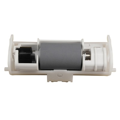
| Деталь: | Roller-Assy-Hopping |
| Парткод: | 44483301 |
| Цена: | 2 100 ₽ |
| Деталь: | Roller-Assy-PickUp |
| Парткод: | 44483601 |
| Цена: | 2 400 ₽ |
| Деталь: | Clutch-3.5 |
| Парткод: | 44261406 |
| Деталь: | Cover-Assy-Top-ADF |
| Парткод: | 44530101 |
| Деталь: | Guide-Assy-A |
| Парткод: | 44532401 |
| Деталь: | Roller-Assy-Eject-ADF |
| Парткод: | 44534901 |
| Деталь: | CLUTCH |
| Парткод: | 44261401 |
| Деталь: | CONN Cord-AMP3P-AMP3P- AMP6P |
| Парткод: | 44595201 |
| Деталь: | CONN Cord-AMP4P-AMP4P |
| Парткод: | 44595601 |
| Деталь: | Clutch-3.5 |
| Парткод: | 44261406 |
Коды ошибок
001
002, 006, 009, 011
020
024, 025
030
031, 036
040
041
042, 043, 045
052
064
067, 068
069
070
072
073
074, 075
081
104
106
112
121
122
123
124
128.05
128.08
131 ... 134
142
153
154
155
160 ... 163
167
168
170, 171
172, 173
174
175
176, 177
182
190
200, 201, 202
203 ... 214
209
231
250
251
252 ... 255
256, 257
802, 803, 805, 807, 808
811, 812, 813
890
901 ... 904
923
928
933
941, 942, 943, 944
980
983
990
F0C, FFE, FFF
Описание
| Error code: | 001 |
| Display: | Service Call 001: Error |
| Description: | Leading edge of the recording paper fails to reach the Timing Sensor. (1st Cassette) |
| Causes: | Recording paper jam. Timing Sensor abnormal. |
| Remedy: | Is the error display reproducible? Power OFF/ON Replace CU PCB. (Must replace EEPROM) |
| Error code: | 002, 006, 009, 011 |
| Display: | Power OFF/ON 002 : Error 006 : Error 009 : Error 011 : Error |
| Description: | CPU Exception |
| Remedy: | Is the error display provided again? Remove any RAM DIMM and turn off and on the MFP. Replace the CU/ PU board. Reinstall the RAM DIMM. |
| Error code: | 020 |
| Display: | Service Call 020: Error |
| Description: | CU ROM Hash Check Error 1 |
| Causes: | Is program ROM DIMM set properly? Is error recovered by replacing program ROM DIMM? |
| Remedy: | Reset program ROM DIMM. Replace program ROM DIMM. Replace TIG board. (Replace EEPROM) |
| Error code: | 024, 025 |
| Display: | Inspection is required. 024 : Error 025 : Error |
| Description: | Kanji Font Error |
| Error code: | 030 |
| Display: | Service Call 030: Error |
| Description: | CU Slot1 DIMM RAM Check Error |
| Causes: | Is subject RAM DIMM set properly? Is error recovered by replacing subject ROM DIMM? |
| Remedy: | Reset subject RAM DIMM. Replace RAM DIMM. Replace TIG board. (Replace EEPROM) |
| Error code: | 031, 036 |
| Display: | Inspection is required. 031 : Error 036 : Error |
| Description: | CU optional RAM check error |
| Remedy: | Is RAM DIMM installed properly? Does the MFP recover by replacing the RAM DIMM? Reinstall the RAM DIMM. Replace the RAM DIMM. Replace the CU/ PU board. |
| Error code: | 040 |
| Display: | Service Call 040: Error |
| Description: | CU EEPROM Error |
| Causes: | Is error recovered by replacing EEPROM on CU board? |
| Remedy: | Replace EEPROM. (Recover user environment.) Replace TIG board. (Replace EEPROM) |
| Error code: | 041 |
| Display: | Service Call 041: Error |
| Description: | CU Flash Error Flash ROM error on CU board. |
| Causes: | Does error display reappear? |
| Remedy: | Replace TIG board. (Replace EEPROM.) |
| Error code: | 042, 043, 045 |
| Display: | Contact the Service center. 042: Error~ 043: Error 045: Error |
| Description: | Flash File System Error |
| Remedy: | Failed to access to the Flash ROM that is directly soldered to the CU board. Turn off the power of the printer and back on. Replace the CU board. |
| Error code: | 052 |
| Display: | Power Off/on 052: Error |
| Description: | Image Processor Driver Error |
| Causes: | Does this error message reappear? |
| Remedy: | Is the error display reproducible? Power OFF/ON Replace CU PCB. (Replace EEPROM) |
| Error code: | 064 |
| Display: | Inspection is required. 064 : Error |
| Description: | SD Card Missing Error |
| Remedy: | Is a SD Card installed in the unit, properly? No Reinstall the SD card. |
| Error code: | 067, 068 |
| Display: | Inspection is required. 067 : Error 068 : Error |
| Description: | Interface monitor error |
| Error code: | 069 |
| Display: | Service Call 069:Error |
| Description: | Malfunction of the NIC chip was detected. |
| Causes: | Does this error recur? |
| Remedy: | Does this error recur? Yes Power OFF/ON. Replace the printer control PCB. |
| Error code: | 070 |
| Display: | Service Call 070: Error |
| Description: | CANT_HAPPEN PS firmware fault detected. |
| Causes: | Confirm that error is recovered by turning power OFF/ON. |
| Remedy: | Replace TIG board. (Replace EEPROM.) |
| Error code: | 072 |
| Display: | Service Call 072: Error |
| Description: | Engine communication error I/F error between PU-CU. |
| Causes: | Is CU assembly set properly? Is error recovered by replacing TIG board? |
| Remedy: | Set properly. Replace TIG board. (Replace EEPROM.) Replace PU board. |
| Error code: | 073 |
| Display: | Reboot the printer. 073: Error xxxxxxxx |
| Description: | Video Error Error is detected when expanding the video data. (Illegal data is received.) |
| Remedy: | Is the CU assembly installed normally? Does this error recur? Re-install the CU assembly normally. Change the PC with another PC having high specifications, or alternately reduce resolution power and execute the print again. Replace the CU board. Replace the interface cable. Re-install the PC Printer driver. Is the CU assembly installed normally? Does this error recur? Does the error depend on print Data? Re-install the CU assembly normally. Execute the print again. Print any other data. Replace the CU board. Send the data to design division and request analysis of the data. |
| Error code: | 074, 075 |
| Display: | Reboot the printer. 074: Error xxxxxxxx 075: Error xxxxxxxx |
| Description: | Video Error Error is detected when expanding the video data. |
| Causes: | Is CU assembly set properly? |
| Remedy: | Is the CU assembly installed correctly? Re-install the CU assembly normally. Replace the CU board. |
| Error code: | 081 |
| Display: | Service Call 081: Error |
| Description: | Parameter Match Check Error |
| Remedy: | Normal Read/Write not possible with EEPROM or Flash. If the condition does not change replace CU PCB. |
| Error code: | 104 |
| Display: | Service Call 104: Error |
| Description: | Developer Motor Failure The Developer Motor rotation signal indicates that the motor is no longer operational. |
| Causes: | • Developer Drive Assembly, PL8.1.1 • Engine Control Board, PL9.1.16 • Interlock Switch, PL9.1.11 • FAN/PHD/MOT Harness, PL10.1.9 |
| Remedy: | 1 Check the Developer Drive Assembly for damage. Are any parts of the Developer Drive Assembly damaged or excessively worn? Replace the Developer Drive Assy. Go to Step 2. 2 Check the Developer Motor connection. Is P/J491 connected to the harness? Go to Step 3. Reconnect the Developer Motor. 3 Test the Developer Motor. 1. Close the Interlock Switch while testing. 2. Run the Service Diagnostics Developer Motor test. Does the motor operate? Go to Step 5. Go to Step 4. 4 Check for +24 V to the Developer Motor. Is the +24 V across P/J491-1 <=> P/J 481-5? Go to Step 6. Go to Step 5. 5 Test the Interlock Switch. Run the Service Diagnostics Interlock Switch test. Does the switch function correctly? Go to Step 6. Replace the Interlock Switch. 6 Check all pins on the FAN/PHD/MOT Harness PL10.1.9 for continuity. 1. Disconnect P/J48 and P/J491. 2. Check continuity between J48 <=> J491. Replace the Engine Control Board. Replace the FAN/PHD/MOT Harness. |
| Error code: | 106 |
| Display: | Service Call 106: Error |
| Description: | Motor Failure One of the primary drive motors has failed. |
| Causes: | • Main Drive Assembly, PL8.1.2 • Developer Drive Assembly, PL8.1.1 • Fuser Drive Assembly, PL5.2.25 • Engine Control Board, PL9.1.16 • Interlock Switch, PL9.1.11 |
| Remedy: | 1 Check the motors. Run the Service Diagnostics motor tests to determine the failed part. Is the failed part the Main Drive Motor? Go to. Test the Fuser Motor. 2 Is the failed part the Fuser Drive Motor? Go to. Test the Developer Motor. 3 Is the failed part the Developer Drive Motor? Go to. Replace the Engine Control Board. |
| Error code: | 112 |
| Display: | SVC 112 ERROR |
| Description: | Printhead Error |
| Causes: | Incorrect color DTM installation, incorrect PCU installation, development bias error, MCU, LD control malfunction, loss of synchronization |
| Remedy: | No first Hysnc - yellow Check for the correct installation of all the cables to the system board assembly and to the printhead assembly; J7 and J8 on the system board. Go to “System board”. If the cables are connected correctly to the system board and to the printhead assembly, go to “Printhead diagnostics”. Note: Do not adjust or replace any printhead before performing checks in “Printhead diagnostics” |
| Error code: | 121 |
| Display: | Service Call 121: Error |
| Description: | Fuser Error |
| Causes: | Is cable between PU board andhighvoltage power LSI connected properly? |
| Remedy: | Wrong fuser lamp - BUR - replace the fuser assembly |
| Error code: | 122 |
| Display: | Service Call 122: Error |
| Description: | Finisher Decurler Failure, Code 122 The level of the Decurler Cam Home Sensor did not change 4 seconds after the Decurler Cam Clutch has turned on. |
| Causes: | • Decurler Cam Clutch • Stacker Motor • Finisher Control Board |
| Remedy: | 1 1. Rotate the actuator while running the Decurler Cam Position test in diagnostics. 2. Does the value change between H and L? Go to step 2. Troubleshoot using the transmissive sensor procedure. 2 Does the decurler cam clutch operate in diagnostics? Check for a mechanical problem with the decurler cam clutch drive. If no problem is found replace the clutch. Go to step 3. 3 Is +24 VDC present at P/J 849-1? Replace the decurler cam clutch. Go to step 4. 4 Is +24 VDC present at test point 5 on the finisher control board? Replace the finisher control board. Troubleshoot the +24 VDC interlock circuit. 5 Is +24 VDC present at P/J 847-11 with the Finisher Stacker Motor Down test running in diagnostics? Replace the stacker motor. Replace the finisher control board |
| Error code: | 123 |
| Display: | Service Call 123: Error |
| Description: | Finisher Set Clamp Failure, Code 123 The set clamp home sensor did not turn on within 2 seconds after the set clamp started operation. |
| Causes: | • Set Clamp Solenoid • Finisher Control Board |
| Remedy: | 1 1. Check the Set Clamp home sensor in diagnostics. 2. Does the value change from H to L while rotating the actuator? Go to step 2. Use the transmissive Sensor procedure to diagnose and repair the sensor. 2 Does the solenoid energize when running the Set Clamp Paddle test in diagnostics? Go to step 3. Go to step 4. 3 1. Run the Eject Forward Test and then the Eject Release Test in diagnostics. 2. Does the set clamp paddle turn once? Replace the finisher control board. Go to step 4. 4 Is +24 VDC present at P848A-10? Go to step 5. Go to step 6. 5 Is +24 VDC present at P848A-11? Replace the finisher control board. Replace the set clamp solenoid. 6 Is +24 VDC present at test point 9 on the finisher control board? Replace the finisher control board. Troubleshoot and repair the +24 VDC interlock circuit. |
| Error code: | 124 |
| Display: | Service Call 124: Error |
| Description: | Finisher Communication Failure, Code 124 |
| Remedy: | There are no diagnostic routines for problems involving serial communications. It is recommended that you address the following assemblies in this order: • Finisher Control Board • Engine Control Board • Perform continuity checks on any wiring harnesses involved. |
| Error code: | 128.05 |
| Display: | Inspection is required. 128 : Error 05 |
| Description: | Image drum fan error |
| Remedy: | Is the connector of the fan connected properly? Does the error occur again? Re-connect it properly. Replace the fan motor. Replace the CU/PU board. |
| Error code: | 128.08 |
| Display: | Inspection is required. 128 : Error 08 |
| Description: | Front fan error |
| Remedy: | Is the connector of the fan connected properly? Does the error occur again? Re-connect it properly. Replace the fan motor. Replace the CU/PU board. |
| Error code: | 131 ... 134 |
| Display: | Service Call 131: Y Head 132: M Head 133: C Head 134: K Head |
| Description: | After turning ON the power or when cover is closed, the sensor detects that the unit is missing. |
| Remedy: | 1) Is an Error message displayed? 2) Is the LED head properly mounted? 3) Does the Error take place again? Check the LED head unit. Turn ON power again. Replace the LED head Assy. |
| Error code: | 142 |
| Display: | Contact the Service center. 142: Error |
| Description: | Motor |
| Causes: | • Standard white plate defective, dirty • Moisture inside the scanner unit • SBU to IPU harnesses defective • BCU to IPU harnesses defective • SBU defective • IPU defective • BCU defective |
| Remedy: | DC pick motor, over speed - staging motor - replace the “Staging motor”. If this does not fix the problem, replace the “System board”. |
| Error code: | 153 |
| Display: | Service call 153: Error |
| Description: | Jam at Duplex: Jam D The Duplex Jam Sensor indicates that paper did not reach the sensor on time or that paper remains in the Chute Assembly Out. |
| Causes: | • Duplex Jam Sensor, PL5.4.1 • Jam Sensor Actuator, PL5.4.13 • Duplex Motor Assembly, PL5.4.5 • FRONT/DUP Harness, PL5.3.28 • Chute Assembly Out, PL5.3.1 |
| Remedy: | 1 Check the following for evidence of fault or damage: • Duplex Motor Assembly, PL5.4.5 • JAM Sensor Actuator, PL5.4.13 • Chute Assembly Out, PL5.3.1 Are there any defects? Replace any damaged part. Go to Step 2. 2 Test the Duplex Jam Sensor. Run the Service Diagnostics Jam Sensor test. Does the sensor function correctly? Go to Step 7. Replace the Duplex Jam Sensor and Go to Step 3. 3 Check printer function. Does the printer function correctly after replacing the Duplex Jam Sensor? Complete Go to Step 4. 4 Check the Duplex Jam Sensor signal. Block the Duplex Jam Sensor. Is the voltage across J133-1 <=> J133-2 0 V? Go to Step 6. Go to Step 5. 5 Check FRONT/DUP Harness continuity. 1. Disconnect P/J133 and P/J13. 2. Check continuity between J133 <=> J13 Go to Step 6. Replace the FRONT/DUP Harness. 6 Print a Test Print in Duplex mode Does the sheet reverse in the printer? Replace the Chute Assembly Out. Go to Step 7. 7 Test the Duplex Motor. 1. Close the Interlock Switch during the test. 2. Run the Service Diagnostics Duplex Motor test. Does the Duplex Motor function correctly? Replace the Chute Assembly Out. Go to Step 8. 8 Check for +24 V to the Duplex Motor. Disconnect P/J501. Is there +24 V across P501-6 <=> ground? Go to Step 9. Replace the Engine Control Board. 9 Check all pins on the FRONT/DUP Harness PL5.3.28 for continuity. 1. Disconnect P/J13 and P/J501. 2. Check continuity between J13 <=> P501. Got to Step 10. Replace the FRONT/DUP Harness. 10 Replace the Duplex Motor. Does the error persist? Replace the Engine Control Board. Complete |
| Error code: | 154 |
| Display: | Service Call 154: Error |
| Description: | Jam at Registration Roller: Jam RR The Registration Sensor indicates that paper did not reach the sensor on time or that paper remains in the Registration Chute. |
| Causes: | • Registration Sensor, PL4.1.3 • Registration Sensor Actuator, PL4.1.1 • Registration Roller Assembly, PL4.2.1 |
| Remedy: | 1 Check the following for damage. • Registration Sensor Actuator, PL4.1.1 • Registration Roller Assembly, PL4.2.1 Is there any damage? Clean or replace as needed. Go to Step 2. 2 Test the Registration Sensor. Run the Service Diagnostics Registration Sensor test. Does the sensor function correctly? Go to Step 6. Go to Step 3. 3 Check the Registration Sensor connection. Is the Registration Sensor connected to the harness? Go to Step 4. Reconnect. 4 Check all pins on the REGISNS Harness PL 4.1.4 for continuity. 1. Disconnect P/J181 and P/J18. 2. Check continuity between J181 <=> J18. Go to Step 5. Replace the Registration Sensor Harness. 5 Check the Registration Sensor signal. Block the Registration Sensor. Verify the voltage between P/J18-3 <=> P/J18-2 on the Engine Control Board is 0 VDC. Go to Step 6. Replace the Registration Sensor. 6 Test the Registration Clutch. 1. Close the Interlock Switch while testing. 2. Run the Service Diagnostics Registration Clutch test. Does the clutch function correctly? Go to Step 8. Go to Step 7. 7 Check the Registration Clutch resistance. Disconnect connector P/J192. Is the resistance between J192-1 <=> J192-2 less than 200ƒ¶? Go to Step 8. Replace the Registration Clutch (Part of the Registration Roller Assembly) 8 Check for +24 V to the Registration Clutch. 1. Disconnect P/J192. 2. Close the Interlock Switch while testing. Is there +24 V across P192-3 <=> ground? Replace the Registration Chute. Replace the Engine Control Board. |
| Error code: | 155 |
| Display: | Service Call 155: Error |
| Description: | Misfeed at Tray 1 (MPT): Jam T1 Paper fed from Tray 1 (MPT) did not reach the Registration Sensor on time. |
| Causes: | • Feed Roller Assembly MPT, PL5.3.20 • Interlock Switch, PL9.1.11 • Registration Sensor, PL4.1.3 • Feed Solenoid, PL5.3.9 • Registration Roller Assembly, PL4.2.1 • Main Drive Assembly, PL8.1.2 |
| Remedy: | 1 Check the following for evidence of fault or damage: • Feed Roller Assembly MPT, PL5.3.20 • Tray 1 (MPT) • Registration Sensor, PL4.1.3 • Main Drive Assembly, PL8.1.2 Remove any foreign objects or paper debris from the paper path. Is there any damage? Replace any damaged or excessively worn parts. Go to Step 2. 2 Test the Registration Sensor. Run the Service Diagnostics Registration Sensor test. Does the sensor function correctly? Go to Step 6. Go to Step 3. 3 Check the Registration Sensor connection. Is the Registration Sensor connected to the harness? Go to Step 4. Connect the sensor. 4 Check all pins of the REGISNR Harness PL4.1.4 for continuity. 1. Disconnect P/J181 and P/J18. 2. Check continuity between J181 <=> J18. Go to Step 5. Replace the Registration Sensor Harness. 5 Check the Registration Sensor signal. Block the Registration Sensor. Verify the voltage between P/J18-3 <=> P/J18-2 on the Engine Control Board is 0 VDC. Replace Registration Sensor. Go to Step 6. 6 If possible, print a Test Print from Tray 1 (MPT). Does the Main Motor function properly? Go to Step 16 Go to Step 7 7 Test the Main Drive Assembly. Run the Service Diagnostics Main Motor test. Does the Main Motor turn? Replace the Engine Control Board. Go to Step 8. 8 Check for +24 V to the Main Drive Motor 1. Disconnect P/J481. 2. Close the Interlock Switch while testing. Is there +24 V across J481-10 <=> J481-8? Go to Step 12. Go to Step 9. 9 Test the Interlock Switch. Run the Service Diagnostics Interlock Switch test. Does the Interlock Switch function correctly? Go to Step 11. Go to Step 10. 10 Check for +5 V to the Interlock Switch Disconnect P/J161. Is there +5 V across P161-1 <=> P161-2? Replace the LVPS. Replace the Interlock Switch. 11 Check FAN/PHD/MOT Harness continuity. 1. Disconnect P/J48 and P/J481. 2. Check continuity between J48 <=> J481 Replace Main Drive Motor Replace FAN/ PHD/MOT Harness. 12 Check Turn Roller function. 1. Perform Steps 1 ~ 3 on. 2. Open and close the front door. 3. Observe the Turn Roller. Does the Turn Roller turn while the machine is warming up? Go to Step 16. Go to Step 13. 13 Test the Turn Clutch. 1. Run the Service Diagnostics Tray 1 (MPT) Turn Clutch test. 2. Close the Interlock Switch while testing. Does the Turn Clutch function normally? Check that the Clutch doesn’t slip. Check the gears for damage. Go to Step 14. 14 Check for +24 V to the Turn Clutch. 1. Disconnect P/J191. 2. Close the Interlock Switch while testing. Is there +24 V across P191-2 <=> ground? Go to Step 15. Replace the Engine Control Board. 15 Check Turn Clutch resistance. Disconnect P/J191. Is the resistance between J191-1 <=> J191-2 less than 200Ω? Go to Step 16. Replace the Turn Clutch (Part of the Registration Roller Assembly). 16 If possible, print a Test print from Tray 1 (MPT). Check the Feed Gear operation. Does the gear function normally? Check for damage or obstructions in the paper path. Go to Step 17. 17 Test the Feed Solenoid. 1. Close the Interlock Switch while testing. 2. Run the Service Diagnostics Tray 1 (MPT) Feed Solenoid test. Does the Feed Solenoid function normally? Check that the Feed Solenoid spring and stopper disengage correctly. Go to Step 18. 18 Check all pins on the FRONT/DUP Harness PL5.3.28 for continuity. 1. Disconnect P/J132 and P/J13. 2. Check continuity between J13 <=> P132. Go to Step 19. Replace the FRONT/DUP Harness Assembly. 19 Check Feed Solenoid resistance. Disconnect connector P/J132. Is the resistance between J132-1 <=> J132-2 less than 100Ω? Replace the Engine Control Board. Replace the Feed Solenoid. |
| Error code: | 160 ... 163 |
| Display: | Service Call 160: Y Toner 161: M Toner 162: C Toner 163: K Toner |
| Description: | Error detected by toner sensor. |
| Causes: | 1) Is error message displayed? 2) Does error reoccur? |
| Remedy: | Replace toner sensor or assembly (Y71-PWB). Same as above. |
| Error code: | 167 |
| Display: | Service Call 167: Error |
| Description: | Motor |
| Causes: | Is the error message displayed? Does this error recur? |
| Remedy: | The incorrect configuration ID. See “Web oiler fuser kit installation” on page 4-88 to set configuration ID. |
| Error code: | 168 |
| Display: | Service Call 168: Error |
| Description: | Motor |
| Causes: | Is the error message displayed? Does this error recur? |
| Remedy: | Unknown manufacture type - perform “Motor Detect” on page 3-18. If you do not find the problem after performing the test, call your next level support. |
| Error code: | 170, 171 |
| Display: | Contact the Service center. 170: Error 171: Error Note) |
| Description: | Short-circuit or open-circuit of fuser thermistor is detected. |
| Causes: | Does error reoccur? |
| Remedy: | Does this error recur? Turn on the power again. Replace the fuser unit. |
| Error code: | 172, 173 |
| Display: | Contact the Service center. 172: Error 173: Error |
| Description: | The fuser thermistor has detected an abnormal temperature (high temperature or low temperature.) |
| Causes: | Does error reoccur? |
| Remedy: | Turn on the power again. Does this error recur? Replace the fuser unit. Replace the low voltage power supply unit. |
| Error code: | 174 |
| Display: | Contact the Service center. 174: Error |
| Description: | Motor |
| Causes: | Does this error recur? |
| Remedy: | Mirror motor lost lock - magenta - go to “Printhead diagnostics” on page 3-1. Note: Do not adjust or replace any printhead before performing checks in “Printhead diagnostics” on page 3-1. |
| Error code: | 175 |
| Display: | Contact the Service center. 175: Error Note) |
| Description: | Motor |
| Causes: | Does this error recur? |
| Remedy: | Mirror motor lock not achieved - yellow - go to “Printhead diagnostics” on page 3-1. Note: Do not adjust or replace any printhead before performing checks in “Printhead diagnostics” on page 3-1. |
| Error code: | 176, 177 |
| Display: | Contact the Service center. 176: Error 177: Error |
| Description: | The backup roller thermistor has detected an abnormal temperature (high temperature or low temperature.) |
| Causes: | Does error reoccur? |
| Remedy: | Does this error recur? Turn on the power again. Replace the fuser unit. Replace the low voltage power supply unit. |
| Error code: | 182 |
| Display: | Service call 182: Error |
| Description: | I/F Error, Loc: Tray2 |
| Causes: | • Scanner unit harness loose, defective • Fan, MCU harness loose, defective • SBU Fan motor defective • MCU defective • SIB defective |
| Error code: | 190 |
| Display: | Service Call 190: Error |
| Description: | System Memory Overflow |
| Remedy: | System Memory Overflow Power OFF/ON Replace CU PCB. (Replace EEPROM) |
| Error code: | 200, 201, 202 |
| Display: | Service Call 200: Error to 202: Error |
| Description: | PU Firm Download Error Error occurred when downloading PU firmware. |
| Remedy: | Error occurred when downloading PU firmware. After turning ON the power again, try downloading again. (This process isn’t executed for regular operations, therefore, will not occur) |
| Error code: | 203 ... 214 |
| Display: | Re-start the printer. 203: Error 204: Error 207: Error 208: Error 214: Error FOC: Error FFF: Error |
| Description: | CU program error (The error numbers 203 through 214 do not occur under the normal operation.) |
| Causes: | Invalid processing was performed with a CU program. |
| Remedy: | Illegal processing is executed by the CU program. After turning off the power, check for the normal connection CU/ PU board. Then, turn on the power again. |
| Error code: | 209 |
| Display: | Power On/off 209: DOWNLOAD ERROR |
| Description: | Custom Media Table Download Error Failed to download custom media table. |
| Remedy: | Failed to download custom media table. After turning ON the power again, try downloading again. (This process isn’t executed for regular operations, therefore, will not occur) |
| Error code: | 231 |
| Display: | Service Call 231: Error |
| Description: | FGATE OFF error: Bk • The PFGATE ON signal still asserts within 5 seconds after processing the image in normal job or MUSIC for end position [K]. • The PFGATE ON signal still asserts when the next job starts. |
| Causes: | • Defective ASIC (Lupus) • Poor connection between controller and EGB. • Defective EGB |
| Remedy: | 1. Check the connection between the controller board and the BCU. 2. Replace the BCU. 3. Replace the controller board. |
| Error code: | 250 |
| Display: | Service Call 250: Error |
| Description: | Paper Jam Clear Paper Path Leave Job in Finisher area 5 |
| Causes: | • Disconnected or defective harness to synchronizing detector for start position • Defective laser synchronizing detector for start position • Defective LDB |
| Remedy: | Primary: Paper is jammed in the MPF. Secondary: If sheets have been accumulated to be stapled when the jam is detected, the printer alternately flashes the primary and secondary messages indicating the accumulated sheets should not be removed during jam clearing. Note: When the secondary message is displayed, if the accumulated sheets are removed the printer will not reprint these sheets. Also if the print job is completed, the portion of the job printed after the jam will not be stapled. If removing the jammed media does not fix the problem, go to “250 Paper Jam” on page 2-78. |
| Error code: | 251 |
| Display: | SVC 251 ERROR |
| Description: | DMA circuit cut-in error |
| Causes: | • Disconnected or defective harness to synchronizing detector for start position • Defective laser synchronizing detector for start position • Defective LDB |
| Remedy: | Replace the Controller board. |
| Error code: | 252 ... 255 |
| Display: | Inspection is required. 252 : Error - 255 : Error |
| Description: | SD card security error |
| Error code: | 256, 257 |
| Display: | Inspection is required. 256 : Error 257 : Error |
| Description: | SD card error |
| Error code: | 802, 803, 805, 807, 808 |
| Display: | Power OFF/ON Error : 802 Error : 803 Error : 805 Error : 807 Error : 808 |
| Description: | SU Exception |
| Error code: | 811, 812, 813 |
| Display: | PRESS POWER SW FOR 5SEC Error : 811 Error : 812 Error : 813 |
| Description: | SU Communication Error Communication error between the Controller and the Scanner Unit is detected. |
| Remedy: | Communication error between the Controller and the Scanner Unit is detected. Turn off and on the MFP. |
| Error code: | 890 |
| Display: | PRESS POWER SW FOR 5SEC Error : 890 |
| Description: | SU System Memory Overflow |
| Remedy: | Does the error occur again? Yes Turn off and on the MFP. Replace the SU board |
| Error code: | 901 ... 904 |
| Display: | Reboot the printer. 901: Error - 904: Error Note) |
| Description: | Abnormal temperature of belt 901: Shortcircuit 902: Open circuit 903: High temperature 904: Low temperature |
| Remedy: | Is the cable from belt thermistor to the high voltage board connected normally? Does this error recur? Re-connect the cables normally. Turn on the power again. Replace the belt thermistsor. |
| Error code: | 923 |
| Display: | Power Off/on 923: Error |
| Description: | Fuser Error |
| Remedy: | Fuser is too hot during printing or when printer is idle. 1 Fuser lamp (incorrect lamp/ 925 Service Error) Install the correct voltage and wattage lamp or fuser assembly. See “Fuser assembly removal”. If the correct fuser lamp is installed and the 925 error remains, the fuser may have reached standby temperature too quickly. Check that the line voltage is not exceeding the maximum rating for the printer. 2 Fuser lamp fuser top cover assembly Observe the lamp through the left side frame. If the lamp does not come on, do the following: • Remove the redrive assembly. • Remove the fuser assembly, disconnect the LVPS to fuser AC cable from the fuser assembly, and remove the fuser. See “Fuser assembly removal” • Verify that the lamp is installed correctly. If correct, check the continuity of the fuser top cover assembly by verifying the lamp contacts on the right contact assembly. If incorrect, check continuity of the fuser lamp. If incorrect, replace the lamp. If correct, replace the fuser top cover assembly. 3 LVPS LVPS to fuser AC cable CAUTION: When taking measurements for AC power, observe all safety precautions. Measure the AC line voltage between the two connectors on the fuser end of the LVPS to fuser AC cable. If the voltage is incorrect, turn the power off, and remove the LVPS. Measure the AC line voltage between pins CN1-1 and CN1-3 on the board. If correct, check the continuity of the LVPS to fuser AC cable. If incorrect, replace the cable. If the AC line voltage at CN1 is incorrect, check fuse F2. If the fuse is blown, replace the fuse. If the fuse is not blown, replace the LVPS assembly. |
| Error code: | 928 |
| Display: | Power Off/on 928: Error |
| Description: | Failure in the Fuser Motor The Fuser Motor has stopped rotating. Applicable Status Code: Code 928: The Fuser Motor has failed. |
| Causes: | • Fuser Motor, PL2.1.9 • Motor Driver Board, PL2.1.10 • Engine Control Board, PL1.1.4 |
| Remedy: | 1 Test the Fuser Motor. 1. Close the Interlock Switches for test. 2. Run the Service Diagnostics Fuser Motor test. Does the motor operate? Complete. Replace the motor. If the error persists, go to Step 2. 2 Check for +24 V to the Fuser Motor. Is the +24 V across DCHEAT- 3 <=> ground? Go to Step 5. Go to Step 3. 3 Check Motor Driver Board POW24 connector for 24 V. 1. Disconnect POW24. Is the +24 V across POW24 pins 1 and 2? Replace the Motor Driver Board. Go to Step 4. 4 Check for 24 V at the LVPS 1. Disconnect CN2 on the LVPS. Is the +24 V across pins 1 and 2? Replace the POW24 Harness. Replace the LVPS. 5 Check all pins of the DRV1 harness for continuity. Disconnect the DRV1 ribbon cable. Is the cable conductive? Replace the Engine Control Board. Replace the DRV1 Harness. |
| Error code: | 933 |
| Display: | Power Off/on 933: Error |
| Description: | Black Printhead Error |
| Remedy: | 1 Check to ensure that the cables between the LED printhead and the printhead controller board as well as the cables between the printhead controller board and the printer controller board are properly connected. Are they properly connected? Go to step 2. Properly connect the cables. 2 Replace the LED printhead for the affected color. Did this resolve the problem? Problem solved. Replace the printhead controller board, and go to step 3. 3 Did replacement of the printhead controller board resolve the problem? Problem solved. Replace the printer controller board. |
| Error code: | 941, 942, 943, 944 |
| Display: | Power OFF/ON 941 : Error 942 : Error 943 : Error 944 : Error |
| Description: | PU Error A PU error was detected. 941 : Watch Doc Timer Error 942 : Detection of Unassigned Interruption 943 : CPU Error Detection 944 : Dcon Access Error |
| Remedy: | Turn off and on the MFP. When this error occurs again, replace the CU/ PU board. |
| Error code: | 980 |
| Display: | Contact the Service center. 980: Error |
| Description: | <device> Comm |
| Causes: | • See description below this table. |
| Remedy: | The engine is experiencing unreliable communications to the specified device. |
| Error code: | 983 |
| Display: | Power Off/on 983: Error |
| Description: | <device> |
| Causes: | Is more than one toner cartridge of the same color installed? |
| Remedy: | Invalid command received by the specified device. |
| Error code: | 990 |
| Display: | Inspection is required. 990 : Error |
| Description: | <device> |
| Causes: | • Firmware defective: re-boot • Update firmware |
| Remedy: | Indicates an equipment check condition has occurred in the specified device, but the device is unable to identify the exact component failure. Note: <device> can be one of the following: duplex, tray x (1, 2, 3, 4, or 5), envelope feeder or output bin. |
| Error code: | F0C, FFE, FFF |
| Display: | Service call 203: Error 204: Error 207: Error 208: Error 213: Error 214: Error F0C: Error FFE: Error FFF: Error |
| Description: | CU program trouble (203~214 are not generated in usual operation) |
| Remedy: | Incorrect processing is performed by the CU program. Does the error recur? Turn on the power supply again. Replace 86M board. |
