Xerox Phaser 3040
Рейтинг


Модули
Feeder 1
Feeder 3
DRIVE
Electrical 1
Electrical 2
Xerographics 2
Feeder 2
COVERS
Toner Dispense
Fuser
Xerographics 1
Детали Feeder 3

| Деталь: | PLATE LOWER |
| Парткод: | P400238742 |
| Деталь: | Rack Side Guide |
| Парткод: | P400238733 |
| Деталь: | GEAR PINION |
| Парткод: | P400238738 |
| Деталь: | Guide Side MSI L |
| Парткод: | P400238303 |
| Деталь: | Guide Side MSI R |
| Парткод: | P400238737 |
| Деталь: | FOOT ASSY |
| Парткод: | P400238725 |
| Деталь: | Chute Upper |
| Парткод: | P400238316 |
| Деталь: | Roll Assy Pinch REGI (with 3-5) |
| Парткод: | P400239032 |
| Деталь: | Roll Pinch REGI10 |
| Парткод: | P400239041 |
| Деталь: | Roll Pinch REGI30 |
| Парткод: | P400239023 |
| Деталь: | Shaft Pinch REGI |
| Парткод: | P400239010 |
| Деталь: | Registration Roller |
| Парткод: | 059E07550 |
| Деталь: | CHUTE LOW |
| Парткод: | P400239054 |
| Деталь: | SPRING ACTUATOR REGI |
| Парткод: | P400239055 |
| Деталь: | REGISTRATION SENSOR ACTUATOR |
| Парткод: | 120E33031 |
| Цена: | 170 ₽ |
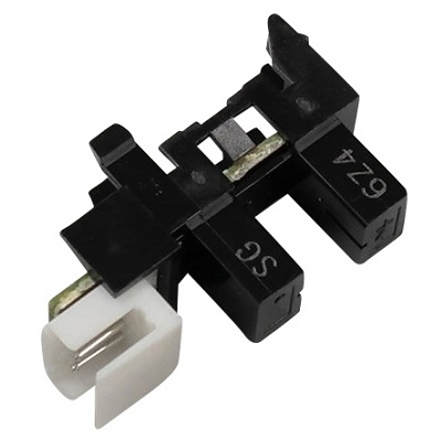
| Деталь: | Registration Sensor |
| Парткод: | 930W00123 |
| Цена: | 750 ₽ |
| Деталь: | Spring Earth REGI |
| Парткод: | P400239062 |
| Деталь: | Bearing REGI Earth |
| Парткод: | P400239019 |
| Деталь: | Bearing REGI Metal Earth |
| Парткод: | P400239065 |
| Деталь: | SPRING TURN |
| Парткод: | P400239070 |
| Деталь: | Bearing REGI Metal |
| Парткод: | P400239057 |
| Деталь: | Bearing REGI |
| Парткод: | P400239069 |
| Деталь: | SPRING REGI CLUTCH |
| Парткод: | P400239040 |
| Деталь: | FLANGE REGI CLUTCH |
| Парткод: | P400239029 |
| Деталь: | GEAR REGI CLUTCH |
| Парткод: | P400239048 |
| Деталь: | COVER SOLENOID |
| Парткод: | P400239035 |
| Деталь: | FEED SOLENOID |
| Парткод: | 121E22993 |
| Деталь: | HARNESS ASSY REG SNS |
| Парткод: | P400239064 |
| Деталь: | Upper Harness Guide |
| Парткод: | P400239036 |
| Деталь: | HVPS |
| Парткод: | 105K30870 |
| Деталь: | MCU Board |
| Парткод: | 960K61093 |
| Деталь: | FFC ASSY MAIN MOT |
| Парткод: | P400239061 |
| Деталь: | FFC ASSY MC-HV |
| Парткод: | P400239050 |
| Деталь: | FFC ASSY MC-ES |
| Парткод: | P400239015 |
| Деталь: | DISP MOT Harness |
| Парткод: | P400239016 |
| Деталь: | LV-MC Harness |
| Парткод: | P400239058 |
| Деталь: | LV-MCES Harness |
| Парткод: | P400239067 |
| Деталь: | MC-LP Harness |
| Парткод: | P400239030 |
| Деталь: | Screw M3x6B |
| Парткод: | P400239043 |
| Деталь: | Rear Door Interlock Switch |
| Парткод: | 110K16521 |
| Деталь: | Harness Guide FR |
| Парткод: | P400239022 |
| Деталь: | Harness Guide IL |
| Парткод: | P400239063 |
| Деталь: | Plate ESS |
| Парткод: | P400239045 |
| Деталь: | Holder Inlet |
| Парткод: | P400239026 |
| Деталь: | Guide Inlet |
| Парткод: | P400239017 |
| Деталь: | Harness Guide R |
| Парткод: | P400239046 |
| Деталь: | PWB Assy ESS 3010 US (IP Board) |
| Парткод: | 676K13181 |
| Деталь: | PWB Assy ESS 3010 RU/IN (IP Board) |
| Парткод: | 676K10931 |
| Деталь: | PWB Assy ESS 3040 US/EU (IP Board) |
| Парткод: | 676K10941 |
| Деталь: | PSLV RIC Assy (with 10,11) |
| Парткод: | P400239085 |
| Деталь: | SW Assy RIC (Power Switch Assembly) |
| Парткод: | P400239018 |
| Деталь: | LVPS 110V |
| Парткод: | 105E19900 |
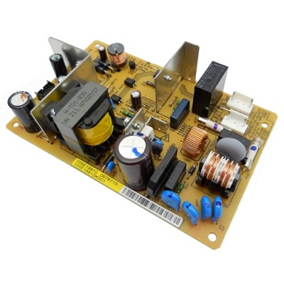
| Деталь: | LVPS 220V |
| Парткод: | 105E19910 |
| Деталь: | LVPS Insulator |
| Парткод: | P400239034 |
| Деталь: | Plate LVPS |
| Парткод: | P400239068 |
| Деталь: | Screw S+M4x6B |
| Парткод: | P400239037 |
| Деталь: | Screw M3x6B |
| Парткод: | P400239038 |
| Деталь: | Power Cord DAO |
| Парткод: | 675K 17830 |
| Деталь: | Power Cord B220V |
| Парткод: | 675K 17660 |
| Деталь: | HSG Assy Xero High |
| Парткод: | P400239042 |
| Деталь: | Spring FG D A4M |
| Парткод: | P400239033 |
| Деталь: | Spring FG AD A4M |
| Парткод: | P400239060 |
| Деталь: | Head Assy R |
| Парткод: | P400239053 |
| Деталь: | Spring LPH AD A4M |
| Парткод: | P400239025 |
| Деталь: | Spring LPH D A4M |
| Парткод: | P400239012 |
| Деталь: | Cover FFC A4M |
| Парткод: | P400239013 |
| Деталь: | Core Ferrite |
| Парткод: | P400239051 |
| Деталь: | Cable FFC |
| Парткод: | P400239039 |
| Деталь: | Roll Assy MSI (with 1-7) (Feed Roll Assembly) |
| Парткод: | 059K71563 |
| Деталь: | Cam MSI L |
| Парткод: | P400238392 |
| Деталь: | Roll Core |
| Парткод: | P400238726 |
| Деталь: | ROLL ASSY FEED |
| Парткод: | P400238728 |
| Деталь: | HOLDER FEED |
| Парткод: | P400238744 |
| Деталь: | SHAFT FEED |
| Парткод: | P400238745 |
| Деталь: | Cam MSI R |
| Парткод: | P400238317 |
| Деталь: | Plate Assy Bottom (with 9,10) (Bottom Plate) |
| Парткод: | 815K07610 |
| Деталь: | Pad MSI |
| Парткод: | P400238746 |
| Деталь: | Plate BTM |
| Парткод: | P400238732 |
| Деталь: | Holder BTM L |
| Парткод: | P400238741 |
| Деталь: | Holder BTM R |
| Парткод: | P400238739 |
| Деталь: | FOLLOWER L |
| Парткод: | P400239066 |
| Деталь: | FOLLOWER R |
| Парткод: | P400239047 |
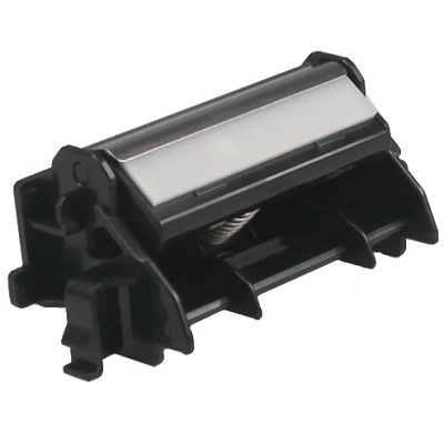
| Деталь: | Housing Assy Pad (Separator Pad Assembly) |
| Парткод: | 848K49666 |
| Цена: | 1 400 ₽ |
| Деталь: | Arm MSI R |
| Парткод: | P400239021 |
| Деталь: | SPRING NF |
| Парткод: | P400239031 |
| Деталь: | Arm MSI L |
| Парткод: | P400239009 |
| Деталь: | Feed Gear |
| Парткод: | 807E36162 |
| Деталь: | SPRING FEED |
| Парткод: | P400239028 |
| Деталь: | Tray Assy Extension (with 2,3) |
| Парткод: | 050K69140 |
| Деталь: | Tray Extension 1 |
| Парткод: | P400238722 |
| Деталь: | Tray Extension 2 |
| Парткод: | P400238729 |
| Деталь: | Cover Assy Top (with 5-7) |
| Парткод: | 848K60170 |
| Деталь: | COVER TOP |
| Парткод: | 848K60180 |
| Деталь: | Guide Light Opp |
| Парткод: | P400238735 |
| Деталь: | Button Opp |
| Парткод: | P400238731 |
| Деталь: | Rear door |
| Парткод: | 848K59910 |
| Деталь: | BEARING BTR L |
| Парткод: | 013E39621 |
| Деталь: | BEARING BTR R |
| Парткод: | 013E39631 |
| Деталь: | Roll Assy BTR (Transfer Roller) |
| Парткод: | 022K76990 |
| Деталь: | COVER REAR INNER |
| Парткод: | 676K11700 |
| Деталь: | COVER SIDE R |
| Парткод: | 848E78630 |
| Деталь: | Cover Assy MSI (with 15-18) (Main Tray) |
| Парткод: | 676K11680 |
| Деталь: | COVER MSI |
| Парткод: | P400238736 |
| Деталь: | Tray MSI Extension |
| Парткод: | P400238734 |
| Деталь: | Lever Guide End |
| Парткод: | P400238730 |
| Деталь: | GUIDE END |
| Парткод: | P400238727 |
| Деталь: | COVER HIPOT |
| Парткод: | 848E66960 |
| Деталь: | Cover Assy Front (With 21,22, label) |
| Парткод: | 676K11671 |
| Деталь: | COVER FRONT |
| Парткод: | P400238723 |
| Деталь: | COVER WINDOW TNR |
| Парткод: | P400238724 |
| Деталь: | COVER SIDE L |
| Парткод: | 848E78620 |
| Деталь: | TONER DISPENSER ASSY |
| Парткод: | 094K93230 |
| Деталь: | TONER MOTOR |
| Парткод: | 127K61370 |
| Цена: | 1 400 ₽ |
| Деталь: | Wire Earth Motor |
| Парткод: | P400239014 |
| Деталь: | Screw M3x6B |
| Парткод: | P400239027 |
| Деталь: | TONER CARTRIDGE |
| Парткод: | P400239052 |
| Деталь: | HARNESS ASSY DCRA |
| Парткод: | P400239024 |
| Деталь: | Plate Upper |
| Парткод: | P400239071 |
| Деталь: | Spring Assy Track AD (With 3,4) |
| Парткод: | P400239056 |
| Деталь: | HOLDER SPRING |
| Парткод: | P400239049 |
| Деталь: | Spring Track AD |
| Парткод: | P400239011 |
| Деталь: | Housing Assy Deve High |
| Парткод: | P400239059 |
| Деталь: | Gear D3 |
| Парткод: | P400238297 |
| Деталь: | Bracket Assy Gear D3 |
| Парткод: | P400239020 |
Коды ошибок
010-397
016-315
016-317
016-501
016-502
016-718
016-719
016-720
016-744
016-745
016-749
024-340
024-360
024-371
024-958
024-963
041-340
061-370
075-100
075-921
077-100
077-104
077-106
077-108
077-109
077-304
077-900
077-901
091-402
092-651
092-661
093-426
093-926
093-933
093-974
116-314
116-323
116-325
116-326
116-335
116-355
117-331 ... 117-366
124-333
191-310
Описание
| Error code: | 010-397 |
| Display: | 010-397 Code:xxxxxxxx Restart Printer |
| Description: | IOT Fuser Failure Detect Fuser Error |
| Causes: | • Fuser Assembly (PL7.1.1) • Heater Harness Assembly (PL7.1.5) • Top Harness Assembly (PL18.2.5) • LVPS (PL18.1.34) • MCU Board (PL18.1.13) |
| Remedy: | 1 Check the Fuser Assembly installation Are the Fuser Assembly, and the drawer connector (DP/J281) of the printer installed properly (without a bent pin, or any foreign or burnt objects, etc.)? Go to step 2. Reinstall the Fuser Assembly. 2 Check the Fuser Assembly connection Check the connection between the Fuser Assembly and the MCU Board, and the connection between the Fuser Assembly and the LVPS. Are P/J281, P/J28, and P/J47 connected securely? Go to step 3. Connect P/J281, P/J28, and P/J47 securely. 3 Check the connections between LVPS and the MCU Board Check the connection between the LVPS and the MCU Board. Are P/J508 and P/J29 connected securely? Go to step 4. Connect P/J508 and P/J29 securely. 4 Check the Heater Harness Assembly continuity. Is each cable of P/J281<=>P/J47 continuous? Go to step 5. Replace the Heater Harness Assembly. 5 Check the Top Harness Assembly continuity. Is each cable of P/J281<=>P/J28 continuous? Go to step 6. Replace the Top Harness Assembly. 6 Check the power to the Fuser Assembly (+5 VDC) Check if the voltage between the MCU Board ground and the P/J28-2 pin is about +5 VDC. Go to step 7. Refer to “+5 VDC Power FIP”. 7 Check after replacing the Fuser Assembly Replace the Fuser Assembly. Does the error still occur? Go to step 8. Finished. 8 Check after replacing the LVPS Replace the LVPS. Does the error still occur? Replace the MCU Board. Finished. |
| Error code: | 016-315 |
| Display: | 016-315 System Restart Printer |
| Description: | IP Board to IIT Communication Error An error occurred between the IIT and the Controller. |
| Causes: | • IP Board, PL7.1.9 • MCU Board, PL7.2.2 • LED Driver Board, PL7.1.5 |
| Remedy: | 1. Reseat all connectors on the IP Board and the MCU Board. Does the error persist? Go to step 2. Complete. 2. Replace the LED Driver Board. Does the error persist? Go to step 3. Complete. 3. Replace the IP Board (Phaser 6020/6022 and WorkCentre 6025 MFP, WorkCentre 6027 MFP. Does the error persist when the power is turned on? 1. SaveNVM to ESS 2. Replace the MCU Board. 3. LoadNVM from ESS Complete. |
| Error code: | 016-317 |
| Display: | 016-317 Restart Printer Contact Support If Message Returns |
| Description: | ESS ROM Main Check Fail 016-317: The standard Page Memory is corrupted. |
| Causes: | • IP Board, PL7.1.9 • MCU Board, PL7.2.2 • LED Driver Board, PL7.1.5 |
| Remedy: | 1. Reseat all connectors on the IP Board and the MCU Board. Does the error persist? Go to step 2. Complete. 2. Replace the LED Driver Board. Does the error persist? Go to step 3. Complete. 3. Replace the IP Board (Phaser 6020/6022 and WorkCentre 6025 MFP, WorkCentre 6027 MFP. Does the error persist when the power is turned on? 1. SaveNVM to ESS 2. Replace the MCU Board. 3. LoadNVM from ESS Complete. |
| Error code: | 016-501 |
| Display: | Write Flash Error 016-501 System Contact Support If Message Returns |
| Description: | Controller Boot Flash Write Error Unable to write the Download File of Controller Boot into the Flash ROM. |
| Causes: | • IP Board. (3010/3040) • IP Board. (3045) • MCU Board. |
| Remedy: | 1. Turn the power OFF and ON. 2. If the problem persists, replace the ESS/MCU PWB (PL 18.3). |
| Error code: | 016-502 |
| Display: | Write Flash Error 016-502 System Contact Support If Message Returns |
| Description: | UI Panel Download Flash Write Error Unable to write the Download File of UI Panel into the Flash ROM. |
| Causes: | • IP Board. (3010/3040) • IP Board. (3045) • MCU Board. |
| Remedy: | 1. Turn the power OFF and ON. 2. If the problem persists, replace the following parts in sequence: • ESS/MCU PWB (PL 18.3) • UI PWB (PL 1.10) |
| Error code: | 016-718 |
| Display: | Memory Full 016-718 Printer Job too Large |
| Description: | Memory Over flow |
| Causes: | • Optional Memory Card (SFP PL8.1.15; MFP PL8.1.4) |
| Remedy: | 1 Check for memory expansion. Is additional memory installed? Is the additional memory installed properly? Go to step 2. Install additional memory. Or, reinstall it properly. 2 In the printer driver, set the Print Mode to “Standard”. Does the error persist during printing? Go to step 3. Complete. 3 In the Control Panel, go to Admin Menu > Maintenance (Mode) and delete data by executing Clear Storage. Does the error persist during printing? The current printing job process cannot be continued because the memory capacity is exceeded. Complete. |
| Error code: | 016-719 |
| Display: | Decode Error 016-719 Printer Job Failure |
| Description: | Decode Error Decode error is detected. |
| Causes: | • IP Board, PL7.1.9 • MCU Board, PL7.2.2 |
| Remedy: | 1. Reseat all connectors on the IP Board and the MCU Board. Does the error persist? Go to step 2. Complete. 2. Replace the IP Board (Phaser 6020/6022 and WorkCentre 6025 MFP, WorkCentre 6027 MFP. Does the error persist when the power is turned on? 1. SaveNVM to ESS 2. Replace the MCU Board. 3. LoadNVM from ESS Complete. |
| Error code: | 016-720 |
| Display: | PDL Request 016-720 Printer Data Violation |
| Description: | PDL Error |
| Causes: | • IP Board (ESS) (SFP PL8.1.7; MFP PL8.1.2) |
| Remedy: | 1 Check the cable between the Printer and PC (or Printer and Hub). - For local printer: USB cable (USB2.0) - For network printer: Ethernet cable (10Base-T/100Base-TX / 1000Base-T) Does the cable meet the specifications? Go to step 2. Use a cable that meets the specifications. - For local printer: USB cable (USB2.0) - For network printer: Ethernet cable(10Base-T/ 100Base-TX / 1000Base-T) 2 Plug and unplug the cable. (USB cable or I/F cable) Does the error still occur when printing? Go to step 3. Complete. 3 Replace the cable. (USB cable or I/F cable) Does the error still occur when the power is turned Off and On? Replace the IP Board. Complete. |
| Error code: | 016-744 |
| Display: | Format Error 016-744 System Invalid Data |
| Description: | Download Check Sum Error Cause: Download file checksum is invalid. |
| Causes: | • IP Board. (3010/3040) • IP Board. (3045) • MCU Board. |
| Remedy: | 1. Turn the power Off and On to check that the error recurs. 2. Re-download the correct file. 3. Check the cable between the Printer and PC (or Printer and Hub). • For local printer: USB cable. • For network printer: Ethernet cable. 4. Take corrective actions at the host side. |
| Error code: | 016-745 |
| Display: | Format Error 016-745 System Invalid Data |
| Description: | Download header Error Cause: Download file header is invalid. |
| Causes: | • IP Board. (3010/3040) • IP Board. (3045) • MCU Board. |
| Remedy: | 1. Turn the power Off and On to check that the error recurs. 2. Re-download the correct file. 3. Check the cable between the Printer and PC (or Printer and Hub). • For local printer: USB cable. • For network printer: Ethernet cable. 4. Take corrective actions at the host side. |
| Error code: | 016-749 |
| Display: | PJL Request 016-749 Printer Data Violation |
| Description: | PJL Request Error The print data cannot be processed by PJL. |
| Causes: | • IP Board, PL7.1.9/7.1.16 • MCU Board, PL7.2.2 |
| Remedy: | 1. Reseat all connectors on the IP Board and the MCU Board. Does the error persist? Go to step 2. Complete. 2. Replace the IP Board (Phaser 6020/6022 and WorkCentre 6025 MFP, WorkCentre 6027 MFP. Does the error persist? 1. SaveNVM to ESS 2. Replace the MCU Board. 3. LoadNVM from ESS Complete. |
| Error code: | 024-340 |
| Display: | 024-340 Code:xxxxxxxx Restart Printer |
| Description: | IOT Firmware Error Detect Firmware Error |
| Causes: | • MCU Board (PL18.1.13) |
| Remedy: | 1 Check the version of the MCU Board firmware Is the MCU Board firmware of the latest version? Replace the MCU Board. Upgrade the firmware of the MCU Board. |
| Error code: | 024-360 |
| Display: | 024-360 System Restart Printer Contact Support If Message Returns |
| Description: | MCU DownLoad Error MCU-F/W download failure |
| Error code: | 024-371 |
| Display: | 024-371 System Restart Printer Contact Support If Message Return |
| Description: | IOT-ESS Communication Fail Communication fail between IOT and ESS. |
| Remedy: | Replace the IP Board. |
| Error code: | 024-958 |
| Display: | Paper Size Mismatch 024-958 Printer Load Paper then Press P AAAAA (or BBBBB) |
| Description: | Paper Size Mismatch The size of paper in the MFP (or PSI) does not match the specified print size. AAAAAA: Paper Size BBBBBB: Paper Type |
| Causes: | • Registration Sensor, PL2.3.5 • Registration roller bushing(s) and spring(s) |
| Remedy: | 1. Check the Regi Sensor in diagnostics. Does the display change when the actuator is moved? Go to step 2. Replace the Regi Sensor. 1. Check the registration rollers. Are all the rollers in contact with even pressure on each side? Are the registration pressure roller bushings and springs correctly installed? Go to step 3. Correct the registration roller installation issue. 1. Is the transfer roller mounted correctly and not binding? Replace the MCU Board 1. SaveNVM to ESS 2. Replace the MCU Board. 3. LoadNVM from ESS Correct the transfer roller mounting issue. |
| Error code: | 024-963 |
| Display: | No Suitable Paper 024-963 Printer Load Paper |
| Description: | No Suitable Paper The MFP (or PSI) has run out of paper or the size (or type) of paper does not match the specified print size (or type). XXXXXX: Paper Size YYYYYY: Paper Type |
| Causes: | • Registration Sensor, PL2.3.5 • Harness Assembly RKN SNS, PL2.2.25 • MCU Board, PL7.2.2 |
| Remedy: | 1. Check the Regi Sensor in CE Diag. Does the display change when the actuator is moved? Go to step 2. Replace the Regi Sensor. 2. Check the Registration Rollers. Are all the rollers in contact with even pressure on each side. Are the registration pressure roller bushings ad springs correctly installed? Go to step 3. Correct any Registration Roller installation issues. 3. Is the Transfer Roller mounted correctly and not binding? 1. SaveNVM to ESS 2. Replace the MCU Board. LoadNVM from ESS. Correct any Transfer Roller mounting issues. |
| Error code: | 041-340 |
| Display: | 041-340 Code:xxxxxxxx Restart Printer |
| Description: | IOT NVRAM Error |
| Causes: | • Imaging Unit (PL4.1.21) • MCU Board (SFP PL8.2.13; MFP PL8.3.6) • EEPROM Board (SFP PL8.2.16; MFP PL8.3.4) • PHD XPRO Harness Assy (PL9.1.11) |
| Remedy: | 1 Does the error still occur after cycling the power On and Off several times? Go to step 2. Complete.a 2 Reseat the Imaging Unit and four Toner Cartridges. Does the error still occur when the power is turned Off and On? Go to step 3. Complete.a 3 Reseat the MCU Board. Does the error still occur when the power is turned Off and On? Go to step 4. Complete.a 4 Check the connectors for connection. Check the connections between the PWBA EEPROM and MCU Board. Are P/J 144, and P/J 42 connected surely? Go to step 6. Reconnect the connector(s) P/ J42 and P/ J144 securely, then go to step 5. 5 Does the error still occur when the power is turned Off and On? Go to step 6. Complete. 6 Check the PHD XPRO Harness Assy for continuity. Disconnect J42 from the MCU Board. Disconnect J144 from the EEPROM Board. Is each cable of J42 <=> J144 continuous? Go to step 7. Replace the PHD XPRO Harness Assy 7 Check the power to the EEPROM Board. Disconnect J42 from the MCU Board. Is the voltage across P42-3 <=> ground on the MCU Board, about +3.3 VDC? Replace the EEPROM Board Go to step 8. 8 Replace the MCU Board. Does the error still occur when the power is turned Off and On? Go to “Electrical Noise” on page 4-79. Complete. |
| Error code: | 061-370 |
| Display: | 061-370 Printer Code:xxxxxxxx Restart Printer |
| Description: | IOT ROS Failure Detect ROS Failure |
| Causes: | • Laser Unit (PL2.1.1) • Top Harness Assembly (PL18.2.5) • LVPS (PL18.1.34) • MCU Board (PL18.1.13) |
| Remedy: | 1 Check the Laser Unit connection Check the connection between the Laser Unit and the MCU Board, and the connection between the Laser Unit and the PWBA LVPS. Are P/J36, P/J11, and PJ43 connected securely? Go to step 2. Connect P/J36, P/J11, and PJ43 securely. 2 Check the continuity between the LVPS and the Laser Unit Is each cable of P/J43<=>P/J431 continuous? Go to step 3. Replace the Top Harness Assembly. 3 Check the power to the Laser Unit (+5 VDC) Close the interlock switch(es), and check if the voltage between the LVPS ground and the P/J43-2 pin is about +5 VDC. Go to step 4. Replace the LVPS. 4 Check the power to the Laser Unit (+24 VDC) Close the interlock switch(es), and check if the voltage between the MCU Board ground and the P/J36-1 pin is about +24 VDC. Go to step 5. Refer to “+24 VDC Power FIP”. 5 Check the power to the Laser Unit (+3.3 VDC) Check if the voltage between the MCU Board ground and the P/J11-1 pin is about +3.3 VDC. Go to step 6. Refer to “+3.3 VDC Power FIP”. 6 Check after replacing the Laser Unit Replace the Laser Unit. Does the error still occur? Replace the MCU Board. Finished. |
| Error code: | 075-100 |
| Display: | Paper Jam 075-100 Printer Jam at Feed |
| Description: | MSI Misfeed JAM Detect VSYNC On JAM(TBD) |
| Causes: | • Regi Sensor [Regi Chute Assembly] (PL15.2.1) • Bypass Tray Feed Solenoid (PL13.2.9) • Paper Transport Motor [Drive Assembly] (PL3.1.1) • Feed Roller Assembly (PL13.2.10) • Retard Holder Assembly (PL13.3.14) • TA1 Roller Assembly (PL13.1.2) • TA2 Roller Assembly (PL13.1.3) • Bypass Tray Harness Assembly (PL13.2.5) • MCU Board (PL18.1.13) |
| Remedy: | 1 Check the Bypass Tray installation Is the Bypass Tray installed properly? Go to step 2. Install the Bypass Tray properly. 2 Check the paper path Are there any foreign objects, or paper pieces, etc. in the paper path? Remove foreign objects, or paper pieces, etc. Go to step 3. 3 Check the paper feed roller Is the paper feed roller (the roller on the possible causative parts list) installed properly? Go to step 4. Reinstall the paper feed roller. 4 Check the paper feed roller Is the paper feed roller (the roller on the possible causative parts list) deformed or worn out? Replace the paper feed roller. Go to step 5. 5 Check the Regi Sensor operation Execute Digital Input diagnostic test 071-103, and check the Regi Sensor operation. Does the Regi Sensor function normally? Go to step 6. 6 Check the Bypass Tray Feed Solenoid operation Execute Digital Output diagnostic test 071-007, and check the Bypass Tray Feed Solenoid operation. Does the Bypass Tray Feed Solenoid function normally? Go to step 7. 7 Check the Paper Transport Motor operation Execute Digital Output diagnostic test 071-004, and check the Paper Transport Motor rotation. Does the Paper Transport Motor function normally? Replace the MCU Board. |
| Error code: | 075-921 |
| Display: | 075-921 Printer Insert Output to Tray |
| Description: | Insert Output To Tray The sheet on which to print an odd-numbered page has not been loaded in the Paper Cassette /Bypass Tray when manual duplex printing is performed. |
| Causes: | • IP Board, PL7.1.9 • MCU Board, PL7.2.2 |
| Remedy: | 1. Reseat the connectors on the IP and MCU Boards then cycle system power. Does the error persist? Go to step 2. Complete. 2. Replace the IP Board (Phaser 6020/6022 and WorkCentre 6025 MFP, WorkCentre 6027 MFP). Does the error persist? 1. SaveNVM to ESS 2. Replace the MCU Board. 3. LoadNVM from ESS Complete. |
| Error code: | 077-100 |
| Display: | Paper Jam 077-100 Printer Jam at Feed |
| Description: | IOT Regi On early JAM |
| Causes: | • Left Side Harness Assy (PL3.1.18) • Registration Input Actuator (PL3.2.11) • Registration Sensor (Sensor Photo) (PL3.2.13) • MCU Board (SFP PL8.2.13; MFP PL8.3.6) • Feeder Assy. (PL 3.1.98) • Drive Clutch Assy. (PL 3.1.97) |
| Remedy: | 1 Check the error. Replace to known good paper. Does the error still occur when printing? Go to step 2. Complete. 2 Open the Front Cover and check the Registration Rollers. Is the metal roller pressed against the rubber roller by the spring pressure? Go to step 3. Replace Feeder Assy. 3 Perform the first part of the procedure “Registration Clutch” on page 4-33 to check the Registration Clutch. Do you hear a click when the clutch is energized? Go to step 4. Replace the Drive Clutch Assy. 4 Perform the procedure “Registration Sensor” on page 4-22 to check operation of the Registration Sensor. Does the number on the screen increase by one when you operate the actuator? Replace the MCU Board. Go to step 5. 5 Check the connections between the MCU Board and Registration Sensor. Are P/J23 and P/J232 connected correctly? Go to step 6. Reconnect P/J23 and/or P/J232. 6 Remove the Lower Chute Assembly to check the shape and operation of the Registration Input Actuator (PL3.2.11). Are the shape and operation normal? Go to step 7. Reseat the Registration Input Actuator. If broken or deformed, replace it. 7 Check the Left Side Harness Assy for continuity. Disconnect J23 from the MCU Board and J232 from the Registration Sensor. Is each cable of J23 <=> J232 continuous? Go to step 8. Replace the Left Side Harness Assy. (PL 3.1.18) 8 Check the power to the Registration Sensor. Disconnect J23 from the MCU Board. Is the voltage across P23-3 <=> ground on the MCU Board, about +3.3 VDC? Go to step 9. Replace the MCU Board. 9 Remove the Lower Chute Assembly (PL3.2.27) to check the operation of the Registration Sensor. Check the voltage across J23-5 <=> ground on the MCU Board. Does the voltage change, when you operate the Registration Input Actuator? Replace the MCU Board. Replace the Registration Sensor |
| Error code: | 077-104 |
| Display: | Paper Jam 077-104 Printer Jam at Exit |
| Description: | RegOff JAM Detect RegOff JAM |
| Causes: | • Regi Sensor [Regi Chute Assembly] (PL15.2.1) • Exit Sensor (PL17.1.11) • Regi Clutch (PL15.1.8) • Paper Transport Motor / Main Motor [Drive Assembly] (PL3.1.1) • Regi Harness Assembly (PL15.2.8) • MCU Board (PL18.1.13) |
| Remedy: | 1 Check the paper path Are there any foreign objects, or paper pieces, etc. on the paper path? Remove the foreign objects, or paper pieces, etc. Go to step 2. 2 Check the paper feed roller Is the paper feed roller (the roller on the possible causative parts list) installed properly? Go to step 3. Reinstall the paper feed roller. 3 Check the paper feed roller Is the paper feed roller (the roller on the possible causative parts list) deformed or worn out? Replace the paper feed roller. Go to step 4. 4 Check the Regi Sensor operation Execute Digital Input diagnostic test 071-103, and check the Regi Sensor operation. Does the Regi Sensor function normally? Go to step 5. 5 Check the Regi Clutch operation Execute Digital Output diagnostic test 071-010, and check the Regi Clutch operation. Does the Regi Clutch function normally? Go to step 6. 6 Check the Paper Transport Motor operation Execute Digital Output diagnostic test 071-004, and check the Paper Transport Motor rotation. Does the Paper Transport Motor function normally? Go to step 7. 7 Check the Exit Sensor operation Execute Digital Input diagnostic test 071-104, and check the Exit Sensor operation. Does the Exit Sensor function normally? Go to step 8. 8 Check the Main Motor operation Execute Digital Output diagnostic test 071-001, and check the Main Motor rotation. Does the Main Motor function normally? Replace the MCU Board. |
| Error code: | 077-106 |
| Display: | Paper Jam 077-106 Printer Jam at Exit |
| Description: | Exit ON JAM Detect Exit ON JAM |
| Causes: | • Regi Sensor [Regi Chute Assembly] (PL15.2.1) • Exit Sensor (PL17.1.11) • Regi Clutch (PL15.1.8) • Paper Transport Motor / Main Motor [Drive Assembly] (PL3.1.1) • Regi Harness Assembly (PL15.2.8) • MCU Board (PL18.1.13) |
| Remedy: | 1 Check the paper path Are there any foreign objects, or paper pieces, etc. on the paper path? Remove the foreign objects, or paper pieces, etc. Go to step 2. 2 Check the paper feed roller Is the paper feed roller (the roller on the possible causative parts list) installed properly? Go to step 3. Reinstall the paper feed roller. 3 Check the paper feed roller Is the paper feed roller (the roller on the possible causative parts list) deformed or worn out? Replace the paper feed roller. Go to step 4. 4 Check the Regi Sensor operation Execute Digital Input diagnostic test 071-103, and check the Regi Sensor operation. Does the Regi Sensor function normally? Go to step 5. 5 Check the Regi Clutch operation Execute Digital Output diagnostic test 071-010, and check the Regi Clutch operation. Does the Regi Clutch function normally? Go to step 6. 6 Check the Paper Transport Motor operation Execute Digital Output diagnostic test 071-004, and check the Paper Transport Motor rotation. Does the Paper Transport Motor function normally? Go to step 7. 7 Check the Exit Sensor operation Execute Digital Input diagnostic test 071-104, and check the Exit Sensor operation. Does the Exit Sensor function normally? Go to step 8. 8 Check the Main Motor operation Execute Digital Output diagnostic test 071-001, and check the Main Motor rotation. Does the Main Motor function normally? Replace the MCU Board. |
| Error code: | 077-108 |
| Display: | Paper Jam 077-108 Printer Jam at Exit |
| Description: | ExitOff ealry JAM Detect ExitOff early JAM |
| Causes: | • Exit Sensor (PL17.1.11) • Exit Clutch 1 / Exit Clutch 2 [Exit Drive Assembly](PL17.1.21) • Main Motor [Drive Assembly] (PL3.1.1) • Exit Sensor Harness Assembly (PL17.1.18) • Sensor Harness Assembly (PL17.1.23) • MCU Board (PL18.1.13) |
| Remedy: | 1 Check the paper path Are there any foreign objects, or paper pieces, etc. on the paper path? Remove the foreign objects, or paper pieces, etc. Go to step 2. 2 Check the paper feed roller Is the paper feed roller (the roller on the possible causative parts list) installed properly? Go to step 3. Reinstall the paper feed roller. 3 Check the paper feed roller Is the paper feed roller (the roller on the possible causative parts list) deformed or worn out? Replace the paper feed roller. Go to step 4. 4 Check the Exit Sensor operation Execute Digital Input diagnostic test 071-104, and check the Exit Sensor operation. Does the Exit Sensor function normally? Go to step 5. 5 Check the Exit Clutch 1 operation Execute Digital Output diagnostic test 071-011, and check the Exit Clutch 1 operation. Does the Exit Clutch 1 function normally? Go to step 6. 6 Check the Exit Clutch 2 operation Execute Digital Output diagnostic test 071-012, and check the Exit Clutch 2 operation. Does the Exit Clutch 2 function normally? Go to step 6. 7 Check the Main Motor operation Execute Digital Output diagnostic test 071-001, and check the Main Motor rotation. Does the Main Motor function normally? Replace the MCU Board. |
| Error code: | 077-109 |
| Display: | Paper Jam 077-109 Printer Jam at Exit |
| Description: | ExitOff JAM Detect IOT Exit Sensor Off JAM |
| Causes: | • Exit Sensor (PL17.1.11) • Exit Clutch 1 / Exit Clutch 2 [Exit Drive Assembly](PL17.1.21) • Main Motor [Drive Assembly] (PL3.1.1) • Exit Sensor Harness Assembly (PL17.1.18) • Sensor Harness Assembly (PL17.1.23) • MCU Board (PL18.1.13) |
| Remedy: | 1 Check the paper path Are there any foreign objects, or paper pieces, etc. on the paper path? Remove the foreign objects, or paper pieces, etc. Go to step 2. 2 Check the paper feed roller Is the paper feed roller (the roller on the possible causative parts list) installed properly? Go to step 3. Reinstall the paper feed roller. 3 Check the paper feed roller Is the paper feed roller (the roller on the possible causative parts list) deformed or worn out? Replace the paper feed roller. Go to step 4. 4 Check the Exit Sensor operation Execute Digital Input diagnostic test 071-104, and check the Exit Sensor operation. Does the Exit Sensor function normally? Go to step 5. 5 Check the Exit Clutch 1 operation Execute Digital Output diagnostic test 071-011, and check the Exit Clutch 1 operation. Does the Exit Clutch 1 function normally? Go to step 6. 6 Check the Exit Clutch 2 operation Execute Digital Output diagnostic test 071-012, and check the Exit Clutch 2 operation. Does the Exit Clutch 2 function normally? Go to step 6. 7 Check the Main Motor operation Execute Digital Output diagnostic test 071-001, and check the Main Motor rotation. Does the Main Motor function normally? Replace the MCU Board. |
| Error code: | 077-304 |
| Display: | Close Rear Cover 077-304 Printer Rear Cover is Open |
| Description: | IOT Cover Rear Open Rear Cover Open |
| Causes: | • Rear Interlock Switch (PL19.1.21) • LVPS (PL18.1.34) |
| Remedy: | 1 Check the Rear Interlock Switch operation Execute Digital Input diagnostic test 041-301, and check the Rear Interlock Switch operation. Does it function normally? Replace the MCU Board. Go to step 2. 2 Check the Rear Interlock Switch connection Check the connection between the Rear Interlock Switch and the LVPS. Is P/J41 connected securely? Go to step 3. Connect P/J41 securely. 3 Check after replacing the Rear Interlock Switch Replace the Rear Interlock Switch. Does the error still occur? Replace the LVPS. Finished. |
| Error code: | 077-900 |
| Display: | Paper Jam Remain at Exit 077-900 Printer Open Rear Cover Remove Paper |
| Description: | IOT Exit JAM |
| Causes: | • Fuser Assy (PL6.1.1) • Fuser Harness Assy (PL6.1.2) • MCU Board (SFP PL8.2.13; MFP PL8.3.6) |
| Remedy: | 1 Check paper feeding Was paper fed from the Manual Feed slot? Go to step 2. Go to step 4. 2 Was the paper inserted straight into the Manual Feed slot and not at an angle? Go to step 4. Insert paper straight into the Manual Feed slot, and go to step 3. 3 Does the error still occur when printing? Go to step 4. Complete. 4 Check the paper condition Is the paper wrinkled or damaged? Replace with new, dry paper, then go to step 5. Go to step 6. 5 Does the error still occur when printing? Go to step 7. Complete. 6 Reload with new paper. Does the error still occur when printing? Go to step 7. Complete. 7 Open and close the Front Cover, and then latch correctly. Does the error still occur when printing? Go to step 8. Complete. 8 Check the Fuser Assy Does any paper and/or foreign substance remain in the Fuser Assy? Remove the paper and/or substance, then go to step 9. Go to step 9. 9 Reseat the Fuser Assy. Does the error still occur when printing? Go to step 10. Complete. 10 Perform the procedure “Exit Sensor” on page 4-23 to check the Exit Sensor operation. Does the number on the screen increase by one, when you operate the Exit Sensor actuator in the Fuser Assy? Replace the MCU Board. Go to step 11. 11 Check the connections between the MCU Board and Fuser Assy. Are P/J17 and P/J171 connected correctly? Go to step 12. Reconnect the connector(s) P/ J17 and/or P/ J171 correctly. 12 Check the Fuser Harness Assy continuity. Remove the Fuser Assy. Disconnect J17 from the MCU Board. Is each cable of J17 <=> P171 continuous? NOTE: P171 is attached to the frame. Go to step 13. Replace the Fuser Harness Assy. 13 Check the power to the Exit Sensor in the Fuser Assy. Disconnect the connector of J17 on the MCU Board. Is the voltage across J17-1 <=> ground on the MCU Board, about +3.3 VDC? Go to step 14. Replace the MCU Board. 14 Check the Exit Sensor operation. Check the voltage across J17-3 <=> ground on the MCU Board. Does the voltage change, when the actuator of the Exit Sensor is operated? Replace the MCU Board. Replace the Fuser Assy. After replacing the Fuser, be sure to reset the Fuser counter. |
| Error code: | 077-901 |
| Display: | Paper Jam Remain at Reg 077-901 Printer Open Rear Cover Remove Paper |
| Description: | IOT Remain Registration JAM |
| Causes: | • Left Side Harness Assy (PL3.1.18) • Registration Input Actuator (PL3.2.11) • Registration Sensor (Sensor Photo) (PL3.2.13) • MCU Board (SFP PL8.2.13; MFP PL8.3.6) • Feeder Assy. (PL 3.1.98) • Drive Clutch Assy. (PL 3.1.97) |
| Remedy: | 1 Check the error. Replace to known good paper. Does the error still occur when printing? Go to step 2. Complete. 2 Open the Front Cover and check the Registration Rollers. Is the metal roller pressed against the rubber roller by the spring pressure? Go to step 3. Replace Feeder Assy. 3 Perform the first part of the procedure “Registration Clutch” on page 4-33 to check the Registration Clutch. Do you hear a click when the clutch is energized? Go to step 4. Replace the Drive Clutch Assy. 4 Perform the procedure “Registration Sensor” on page 4-22 to check the Registration Sensor for operation. Does the number on the screen increase by one when you operate the Registration Input Actuator? Replace the MCU Board. Go to step 5. 5 Remove the Lower Chute Assembly to check the shape and operation of the Registration Input Actuator. Are the shape and operation normal? Go to step 6. Reseat the Registration Input Actuator. If broken or deformed, replace it. 6 Check the connectors of the for connection. Check the connections between the MCU Board and Registration Sensor. Are P/J23 and P/J232 connected correctly? Go to step 7. Reconnect the connector(s) P/ J23 and/or P/ J232 correctly. 7 Check the Left Side Harness Assy for continuity. Disconnect J23 from the MCU Board. Disconnect J232 from the Registration Sensor. Is each cable of J23 <=> J232 continuous? Go to step 8. Replace the Left Side Harness Assy. (PL 3.1.18) 8 Disconnect J23 from the MCU Board and measure the voltage across P23-3 <=> ground on the MCU Board. Is the voltage about +3.3 VDC? Go to step 9. Replace the MCU Board. 9 Check the voltage across P23-5 <=> ground on the MCU Board. Remove the Lower Chute Assembly to check the operation of the Registration Sensor. Does the voltage change when you operate the Registration Input Actuator? Replace the MCU Board. Replace the Registration Sensor |
| Error code: | 091-402 |
| Display: | 091-402 Printer Contact Support If Message Returns |
| Description: | IOT Drum Cartridge Kit Life Pre Warning Detect Drum Life Warning |
| Remedy: | Replace the Imaging Unit. |
| Error code: | 092-651 |
| Display: | 092-651 Code:xxxxxxxx Restart Printer |
| Description: | CDT (ADC) Sensor Error CTD (ADC) sensor error is detected. |
| Causes: | • MCU Board, PL7.2.2 |
| Remedy: | 1. Clean the ADC sensor. Does the error persist when the power is turned on? Go to step 2. Complete. 2. Disconnect the harness at MCU Board P/J14 and at Xerographics Assembly P/J140, and check the harness for continuity. Is the harness continuous? Go to step 3. Repair the harness. 3. 1. SaveNVM to ESS 2. Replace the MCU Board. 3. LoadNVM from ESS Does the error persist? Contact your designated field support for assistance. Complete. |
| Error code: | 092-661 |
| Display: | 092-661 Code:xxxxxxxx Restart Printer |
| Description: | IOT Environment Sensor Error Detect Environment Sensor Error |
| Causes: | • Laser Unit (PL2.1.1) • Top Harness Assembly (PL18.2.5) • LVPS (PL18.1.34) • MCU Board (PL18.1.13) |
| Remedy: | 1 Check the Laser Unit connection Check the connection between the Laser Unit and the MCU Board, and the connection between the Laser Unit and the PWBA LVPS. Are P/J36, P/J11, and PJ43 connected securely? Go to step 2. Connect P/J36, P/J11, and PJ43 securely. 2 Check the continuity between the LVPS and the Laser Unit Is each cable of P/J43<=>P/J431 continuous? Go to step 3. Replace the Top Harness Assembly. 3 Check the power to the Laser Unit (+5 VDC) Close the interlock switch(es), and check if the voltage between the LVPS ground and the P/J43-2 pin is about +5 VDC. Go to step 4. Replace the LVPS. 4 Check the power to the Laser Unit (+24 VDC) Close the interlock switch(es), and check if the voltage between the MCU Board ground and the P/J36-1 pin is about +24 VDC. Go to step 5. Refer to “+24 VDC Power FIP”. 5 Check the power to the Laser Unit (+3.3 VDC) Check if the voltage between the MCU Board ground and the P/J11-1 pin is about +3.3 VDC. Go to step 6. Refer to “+3.3 VDC Power FIP”. 6 Check after replacing the Laser Unit Replace the Laser Unit. Does the error still occur? Replace the MCU Board. Finished. |
| Error code: | 093-426 |
| Display: | Ready to Print 093-42X Printer Cartridge is Close to Life |
| Description: | IOT X Toner Near Life K |
| Remedy: | Replace the Black Toner Cartridge. |
| Error code: | 093-926 |
| Display: | CRUM ID 093-926 Reseat Cartridge |
| Description: | IOT X CRUM ID Error Detect K Toner CRUM ID Warning |
| Causes: | • Black Toner Cartridge (PL5.1.11) |
| Remedy: | 1 Check the Toner Cartridge installation Is a Toner Cartridge other than a Black Toner Cartridge installed? Or, is the installed Toner Cartridge for another printer? Install the right Black Toner Cartridge. Reinstall the Black Toner Cartridge. |
| Error code: | 093-933 |
| Display: | Replace Cart. 093-93X Printer Replace Cartridge |
| Description: | IOT X Toner Life Over K |
| Remedy: | Replace the Black Toner Cartridge. |
| Error code: | 093-974 |
| Display: | Insert Print Cart 093-974 Printer Insert Toner Cartridge |
| Description: | Insert Print Cartridge An unsupported Toner Cartridge (C, M, Y, or K) is detected, or a No Toner Cartridge Installed state was detected. |
| Causes: | • MCU Board, PL7.2.2 • Harn assy dckr, PL4.1.2 |
| Remedy: | 1 Open the Toner Door and check that the Toner Cartridges have been fully installed. Does the error persist? Go to step 2. Complete. 2 Reseat the Toner Cartridges. Does the error persist? Go to step 3. Complete. 3 Disconnect P/J13 on the MCU Board and unlace the harness. Inspect the harness for damage. Is the harness damaged? Repair the harness, then go to step 4. Go to step 4. 4 Does the error persist? Replace the MCU Board. Contact your designated field support for assistance. |
| Error code: | 116-314 |
| Display: | 116-314 System Restart Printer Contact Support If Message Returns |
| Description: | MAC Address Error Cause: On Board Network MAC Address Checksum Error. |
| Causes: | • IP Board. (3010/3040) • IP Board. (3045) • MCU Board. |
| Remedy: | 1. Turn the power Off and On to check that the error recurs, then replace (ESS PWB). |
| Error code: | 116-323 |
| Display: | 116-323 Restart Printer Contact Support If Message Returns |
| Description: | Checksum Error (Fax) Checksum Error for Fax parameter is detected. |
| Causes: | • IP Board, PL7.1.9 • MCU Board, PL7.2.2 |
| Remedy: | 1. Reseat all connectors on the IP Board and the MCU Board. Does the error persist? Go to step 2. Complete. 2. Replace the PACKAGE ASSY FAX LT PL7.1.15 Does the error persist when the power is turned on? Replace the IP Board: Phaser 6020/6022 and WorkCentre 6025 MFP, WorkCentre 6027 MFP. Complete. |
| Error code: | 116-325 |
| Display: | 116-325 System Restart Printer Contact Support If Message Return |
| Description: | Checksum Error (Other) Checksum error for (Other) parameter is detected. |
| Causes: | • IP Board, PL7.1.9 • MCU Board, PL7.2.2 |
| Remedy: | 1. Reseat all connectors on the IP Board and the MCU Board. Does the error persist? Go to step 2. Complete. 2. Replace the IP Board Phaser 6020/6022 and WorkCentre 6025 MFP, WorkCentre 6027 MFP. Does the error persist when the power is turned on? 1. SaveNVM to ESS 2. Replace the MCU Board. 3. LoadNVM from ESS Complete. |
| Error code: | 116-326 |
| Display: | 116-326 System Restart Printer Contact Support If Message Returns |
| Description: | ESS NVRAM2 W/R Check Fail Cause: Detected by master NVRAM W/R check. |
| Causes: | • IP Board. (3010/3040) • IP Board. (3045) • MCU Board. |
| Remedy: | 1. Turn the power Off and On to check that the error recurs, then replace (ESS PWB). |
| Error code: | 116-335 |
| Display: | 116-335 System Restart Printer Contact Support If Message Returns |
| Description: | NVRAM Checksum Error Checksum is not right when NVRAM initialized. |
| Causes: | • IP Board, PL7.1.9/7.1.16 • MCU Board, PL7.2.2 |
| Remedy: | 1 Reseat all connectors on the IP Board and the MCU Board. Does the error persist? Go to step 2. Complete. 2 Replace the IP Board. Does the error persist? Replace the MCU Board, and then go to step 3. Complete. 3 Does the error persist? Contact your designated field support for assistance. Complete. |
| Error code: | 116-355 |
| Display: | 116-355 System Restart Printer Contact Support If Message Return |
| Description: | On Board Network Fatal Error |
| Causes: | • IP Board (ESS) (SFP PL8.1.7; MFP PL8.1.2) |
| Remedy: | 1 Unplug the ethernet cable. Does the error still occur when the power is turned Off and On? Replace the IP Board. Initialize the Network settings and configure the settings again. For details of the Network settings, refer to the User Guide. |
| Error code: | 117-331 ... 117-366 |
| Display: | 117-xxx System Restart Printer Contact Support If Message Return |
| Description: | System Restart An internal IP Board error occurred. |
| Causes: | • IP Board, PL7.1.9 |
| Remedy: | 1 Check the connectors on the IP Board. Are the connections secure? Go to step 3. Securely reconnect the connectors, then go to step 2. 2 Does the error persist? Go to step 3. Complete. 3 Replace the IP Board. Does the error persist? Complete. |
| Error code: | 124-333 |
| Display: | 124-333 Printer Restart Printer |
| Description: | ASIC Failure Restart Printer |
| Causes: | • LED Driver Board, PL7.1.5 • LED/MCU Cable, PL7.1.6 • MCU Board, PL7.2.2 |
| Remedy: | 1. Check connectors P/J23 and P/J1 on the MCU Board and LED Driver Board. Are the connections secure? Go to step 3. Reconnect the connectors P/J23 and P/J1, and then go to step 2. 2. Does the error persist? Go to step 3. Complete. 3. Disconnect the MCU Board P/J23 and the LED Driver Board P/J1, and check the LED/MCU Cable continuity. Is the cable damaged? Replace the LED/MCU Cable. Go to step 4. 4. Replace the LED Driver Board. Does the error persist? 1. SaveNVM to ESS 2. Replace the MCU Board. 3. LoadNVM from ESS Complete. |
| Error code: | 191-310 |
| Display: | 191-310 Restart Printer Contact Support If Message Returns |
| Description: | XERO Life Over The xerographics assembly is at end of life. |
| Remedy: | • Cycle printer power. • If the problem persists, the printer is at the end of life and should be replaced. |
