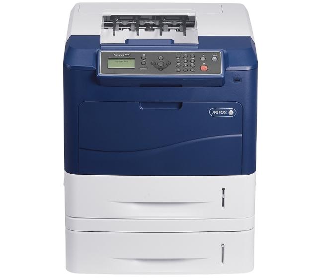
Xerox Phaser 4620DT
Рейтинг

 Снят с производства
Тип устройства
Принтер
Технология печати
лазерная
Макс. формат
A4
Число страниц в месяц
275000
Скорость печати
A4
62
Цветность печати
черно-белая
Общие характеристики |
|
|---|---|
Макс. формат |
A4 |
Тип устройства |
Принтер |
Размещение |
настольный |
Число страниц в месяц |
275 000 |
Телефон |
|
Печать фотографий |
|
Копир |
|
Сканер |
|
Факс |
|
Область применения |
большой офис |
Цветность печати |
|
Технология печати |
лазерная |
Тип |
лазерный/светодиодный |
Принтер |
|
Двусторонняя печать |
|
Печать без полей |
|
Прямая печать |
|
Система непрерывной подачи чернил |
|
Пигментные чернила |
|
Время разогрева |
15 |
Макс, разрешение для ч/б печати |
|
| По X | 1 200 |
| По Y | 1 200 |
Скорость ч/б печати |
|
| A4 | 62 |
Время выхода первого отпечатка |
|
| Ч/б | 7,8 |
Сканер |
|
Стандарт TWAIN |
|
Отправка изображения по e-mail |
|
Слайд-адаптер |
|
Стандарт WIA |
|
Расходные материалы |
|
Количество картриджей |
1 |
Ресурс ч/б картриджа/тонера |
13 000 |
Ресурс фотобарабана |
80 000 |
Печать на: |
|
| Этикетках |
|
| Конвертах |
|
| Матовой бумаге |
|
| Глянцевой бумаге |
|
| Карточках |
|
| Пленках |
|
| CD/DVD |
|
| Рулоне |
|
| Фотобумаге |
|
Плотность бумаги |
|
| Минимальная | 60 |
| Максимальная | 220 |
Факс |
|
PC Fax |
|
Цветной |
|
Телефон |
|
Стандарт DECT |
|
Проводная трубка |
|
Беспроводная трубка |
|
АОН |
|
Caller ID |
|
Автоответчик |
|
Спикерфон |
|
Шрифты и языки управления |
|
Языки управления |
|
| PCL 6 |
|
| PostScript |
|
|
|
|
| PostScript 3 |
|
| PCL 5e |
|
| PCL 5c |
|
| PPDS |
|
| PostScript 2 |
|
Количество установленных шрифтов |
|
| PCL | 81 |
| PostScript | 139 |
Лотки |
|
Подача бумаги |
|
| Стандартная | 1 200 |
| Максимальная | 3 750 |
Вывод бумаги |
|
| Максимальный | 500 |
| Стандартный | 500 |
Финишер |
|
Сортер |
|
Электронная сортировка |
|
Сортировка со сдвигом |
|
Степлер |
|
Брошюровщик |
|
Интерфейсы |
|
Версия USB |
2,0 |
USB |
|
Ethernet (RJ-45) |
|
FireWire (IEEE 1394) |
|
Wi-Fi |
|
Wi-Fi 802.11n |
|
Bluetooth |
|
LPT |
|
AirPrint |
|
Инфракрасный порт |
|
RS-232 |
|
Веб-интерфейс |
|
Устройство для чтения карт памяти |
|
Память/Процессор |
|
Макс, объем памяти |
768 |
Объем памяти |
256 |
Частота процессора |
700 |
Дополнительная информация |
|
Работа от аккумулятора |
|
Экран |
|
Поддержка ОС |
|
| DOS |
|
| Windows |
|
| Linux |
|
| Mac OS |
|
Потребляемая мощность |
|
| В режиме ожидания | 80 |
| При работе | 675 |
Уровень шума |
|
| При работе | 52 |
| В режиме ожидания | 28 |
Габариты |
|
Глубина |
476 |
Ширина |
541 |
Модули
Детали

| Деталь: | Узел отделения бумаги из обходного лотка, в сборе (в держателе) |
| Парткод: | 022N02479 |
| Цена: | 3 700 ₽ |
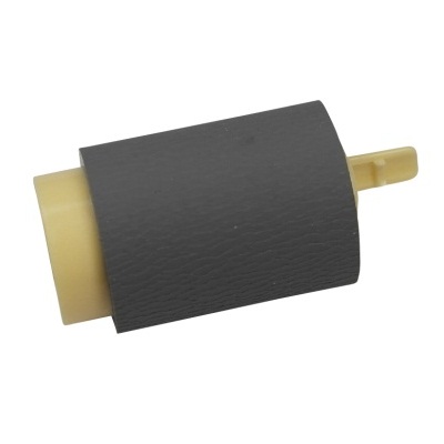
| Деталь: | Узел захвата / подачи бумаги из обходного лотка, в сборе (в держателе) |
| Парткод: | 022N02480 |
| Деталь: | Кассета на 550 листов, в сборе (лоток 2) |
| Парткод: | 050N00562 |
| Цена: | 17 300 ₽ |
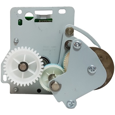
| Деталь: | Редуктор узла подачи бумаги, в сборе (мотор в комплекте) |
| Парткод: | 007N01662 |
| Цена: | 10 800 ₽ |
| Деталь: | Главный редуктор, в сборе |
| Парткод: | 007N01663 |
| Цена: | 22 300 ₽ |
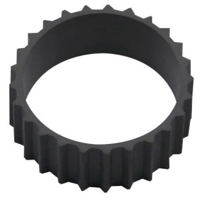
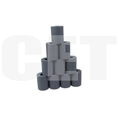
| Деталь: | Транспортировочный ремень (1 шт. / в узле 2 шт.) |
| Парткод: | 023N01310 |
| Цена: | 370 ₽ |
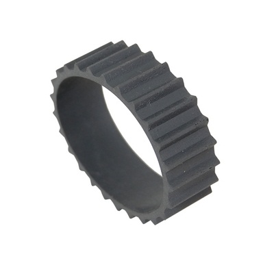
| Деталь: | Транспортировочный ремень (1 шт. / в узле 2 шт.) |
| Парткод: | JC73-00324A |
| Цена: | 500 ₽ |
| Деталь: | Жёсткий диск 160Gb |
| Парткод: | 097N01879 |
| Деталь: | Адаптер беспроводной сетевой печати |
| Парткод: | 097N01880 |
| Цена: | 19 600 ₽ |
| Деталь: | Импульсный стабилизатор напряжения (220В) |
| Парткод: | 105N02158 |
| Цена: | 22 800 ₽ |
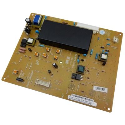
| Деталь: | Imaging high-voltage PCA |
| Парткод: | 105N02193 |
| Цена: | 11 900 ₽ |
| Деталь: | Formatter, exchange, HP Color LaserJet 3000dn and 3000dtn Series only (256 MB) |
| Парткод: | 109N00710 |
| Цена: | 800 ₽ |
| Деталь: | PHOTO-INTERRUPTER |
| Парткод: | 130N01628 |
| Цена: | 1 100 ₽ |
| Деталь: | Редуктор узла термозакрепления, в сборе (мотор в комплекте) |
| Парткод: | 007N01659 |
| Цена: | 7 900 ₽ |
| Деталь: | ROLLER-PRESSURE, ML-1660,8,SUM22 or SUM23 |
| Парткод: | 022N02476 |
| Цена: | 15 200 ₽ |
| Деталь: | ROLLER-HEAT, ML-1660,AL5052,18.1,247.5 |
| Парткод: | 022N02477 |
| Деталь: | Лампа нагрева тефлонового вала (220В) |
| Парткод: | 122N00291 |
| Деталь: | Печь, в сборе (220В) |
| Парткод: | 126N00340 |
| Цена: | 33 000 ₽ |
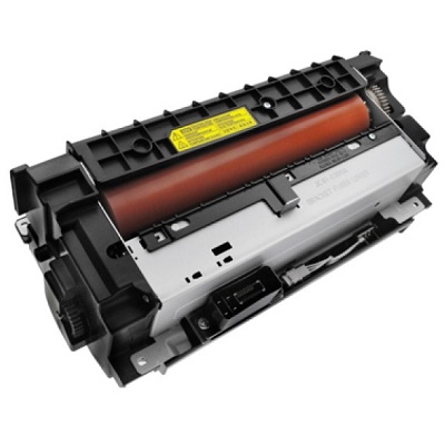
| Деталь: | Печь, в сборе (220В) |
| Парткод: | JC91-01105A |
| Цена: | 22 300 ₽ |
| Деталь: | Control-panel assembly (Western) |
| Парткод: | 002N02989 |
| Деталь: | Дополнительный лоток подачи бумаги (550 листов) |
| Парткод: | 097N01874 |
| Цена: | 21 300 ₽ |
| Деталь: | Дополнительный лоток подачи бумаги |
| Парткод: | 097N01875 |
| Цена: | 58 000 ₽ |
| Деталь: | Финишер (500 листов) |
| Парткод: | 097N01876 |
| Цена: | 45 400 ₽ |
| Деталь: | Выходной лоток на 400 листов с 4-мя отсеками (почтовые ящики) |
| Парткод: | 097N01877 |
| Цена: | 38 700 ₽ |
| Деталь: | Стенд (тумба) |
| Парткод: | 097N01916 |
| Цена: | 17 000 ₽ |
| Деталь: | Модуль двухсторонней печати |
| Парткод: | 097N01923 |
| Деталь: | FUSER ASSEMBLY (220v) |
| Парткод: | 115R00070 |
| Цена: | 18 700 ₽ |
| Деталь: | Узел отделения бумаги из обходного лотка, в сборе (в держателе) |
| Парткод: | 022N02479 |
| Цена: | 3 700 ₽ |
| Деталь: | Узел захвата / подачи бумаги из обходного лотка, в сборе (в держателе) |
| Парткод: | 022N02480 |
| Деталь: | Кассета на 550 листов, в сборе (лоток 2) |
| Парткод: | 050N00562 |
| Цена: | 17 300 ₽ |
| Деталь: | Редуктор узла подачи бумаги, в сборе (мотор в комплекте) |
| Парткод: | 007N01662 |
| Цена: | 10 800 ₽ |
| Деталь: | Главный редуктор, в сборе |
| Парткод: | 007N01663 |
| Цена: | 22 300 ₽ |
| Деталь: | Транспортировочный ремень (1 шт. / в узле 2 шт.) |
| Парткод: | 023N01310 |
| Цена: | 370 ₽ |
| Деталь: | Транспортировочный ремень (1 шт. / в узле 2 шт.) |
| Парткод: | JC73-00324A |
| Цена: | 500 ₽ |
| Деталь: | Жёсткий диск 160Gb |
| Парткод: | 097N01879 |
| Деталь: | Адаптер беспроводной сетевой печати |
| Парткод: | 097N01880 |
| Цена: | 19 600 ₽ |
| Деталь: | Импульсный стабилизатор напряжения (220В) |
| Парткод: | 105N02158 |
| Цена: | 22 800 ₽ |
| Деталь: | Imaging high-voltage PCA |
| Парткод: | 105N02193 |
| Цена: | 11 900 ₽ |
| Деталь: | Formatter, exchange, HP Color LaserJet 3000dn and 3000dtn Series only (256 MB) |
| Парткод: | 109N00710 |
| Цена: | 800 ₽ |
| Деталь: | PHOTO-INTERRUPTER |
| Парткод: | 130N01628 |
| Цена: | 1 100 ₽ |
| Деталь: | Редуктор узла термозакрепления, в сборе (мотор в комплекте) |
| Парткод: | 007N01659 |
| Цена: | 7 900 ₽ |
| Деталь: | ROLLER-PRESSURE, ML-1660,8,SUM22 or SUM23 |
| Парткод: | 022N02476 |
| Цена: | 15 200 ₽ |
| Деталь: | ROLLER-HEAT, ML-1660,AL5052,18.1,247.5 |
| Парткод: | 022N02477 |
| Деталь: | Лампа нагрева тефлонового вала (220В) |
| Парткод: | 122N00291 |
| Деталь: | Печь, в сборе (220В) |
| Парткод: | 126N00340 |
| Цена: | 33 000 ₽ |
| Деталь: | Печь, в сборе (220В) |
| Парткод: | JC91-01105A |
| Цена: | 22 300 ₽ |
| Деталь: | Control-panel assembly (Western) |
| Парткод: | 002N02989 |
| Деталь: | Дополнительный лоток подачи бумаги (550 листов) |
| Парткод: | 097N01874 |
| Цена: | 21 300 ₽ |
| Деталь: | Дополнительный лоток подачи бумаги |
| Парткод: | 097N01875 |
| Цена: | 58 000 ₽ |
| Деталь: | Финишер (500 листов) |
| Парткод: | 097N01876 |
| Цена: | 45 400 ₽ |
| Деталь: | Выходной лоток на 400 листов с 4-мя отсеками (почтовые ящики) |
| Парткод: | 097N01877 |
| Цена: | 38 700 ₽ |
| Деталь: | Стенд (тумба) |
| Парткод: | 097N01916 |
| Цена: | 17 000 ₽ |
| Деталь: | Модуль двухсторонней печати |
| Парткод: | 097N01923 |
| Деталь: | FUSER ASSEMBLY (220v) |
| Парткод: | 115R00070 |
| Цена: | 18 700 ₽ |
Коды ошибок
Описание
Название
XEROX Ролик захвата из кассеты
XEROX Ролик переноса
XEROX Емкость для отработанного тонера
XEROX Тонер-картридж черный (13000 стр.)
XEROX Тонер-картридж черный (30000 стр.)
XEROX Копи-картридж / фотобарабан
XEROX Комплект обслуживания 220V
XEROX Печка в сборе 220V
