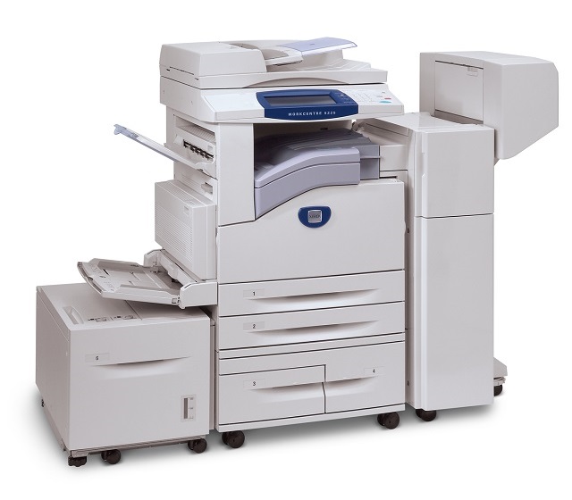
Xerox WorkCentre 5225
Рейтинг


Модули
(Электронные компоненты)
ADF 1
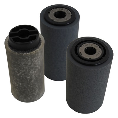
(Подача и захват бумаги)
FRAME L
PANEL
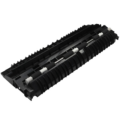
FRAME-TRANSFER
DUPLEX
PAPER FEED
(Внутренние компоненты)
(Узел термозакрепления)
COVERS
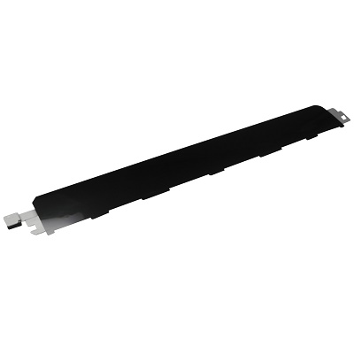
Детали FRAME-TRANSFER

| Деталь: | Кассета на 500 листов, в сборе (лоток 2, 3) |
| Парткод: | 050K61183 |
| Цена: | 25 800 ₽ |
| Деталь: | Ролик замедления бумаги |
| Парткод: | 059K26591 |
| Цена: | 6 300 ₽ |
| Деталь: | PULLEY FEED |
| Парткод: | 059K26691 |
| Цена: | 4 400 ₽ |
| Деталь: | Подталкивающий ролик |
| Парткод: | 059K26702 |
| Цена: | 950 ₽ |
| Деталь: | Duplexing-feed assembly |
| Парткод: | 059K55760 |
| Цена: | 25 800 ₽ |
| Деталь: | Подшипник вала вертикальной подачи бумаги (правый) |
| Парткод: | 013E30110 |
| Цена: | 340 ₽ |
| Деталь: | Imaging high-voltage PCA |
| Парткод: | 105E17880 |
| Цена: | 900 ₽ |
| Деталь: | Модуль памяти (256MB) |
| Парткод: | 497K03680 |
| Цена: | 21 000 ₽ |
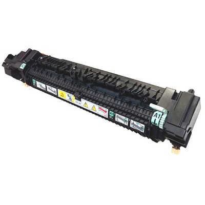
| Деталь: | Печь, в сборе (220В) |
| Парткод: | 126K24993 |
| Цена: | 31 700 ₽ |
| Деталь: | Узел захвата бумаги из автоподатчика документов, в сборе |
| Парткод: | 059K48900 |
| Цена: | 7 900 ₽ |
| Деталь: | Комплект захвата бумаги из автоподатчика документов |
| Парткод: | 604K20760 |
| Цена: | 3 800 ₽ |
| Деталь: | Кассета на 500 листов, в сборе (лоток 2, 3) |
| Парткод: | 050K61183 |
| Цена: | 25 800 ₽ |
| Деталь: | Ролик замедления бумаги |
| Парткод: | 059K26591 |
| Цена: | 6 300 ₽ |
| Деталь: | PULLEY FEED |
| Парткод: | 059K26691 |
| Цена: | 4 400 ₽ |
| Деталь: | Подталкивающий ролик |
| Парткод: | 059K26702 |
| Цена: | 950 ₽ |
| Деталь: | Duplexing-feed assembly |
| Парткод: | 059K55760 |
| Цена: | 25 800 ₽ |
| Деталь: | Подшипник вала вертикальной подачи бумаги (правый) |
| Парткод: | 013E30110 |
| Цена: | 340 ₽ |
| Деталь: | Imaging high-voltage PCA |
| Парткод: | 105E17880 |
| Цена: | 900 ₽ |
| Деталь: | Модуль памяти (256MB) |
| Парткод: | 497K03680 |
| Цена: | 21 000 ₽ |
| Деталь: | Печь, в сборе (220В) |
| Парткод: | 126K24993 |
| Цена: | 31 700 ₽ |
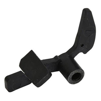
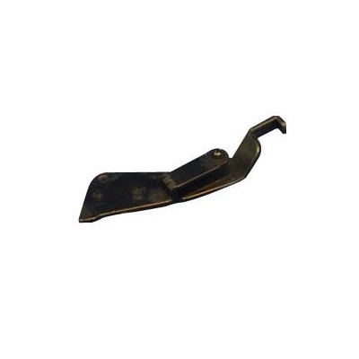
| Деталь: | Флажок датчика выхода бумаги из узла термозакрепления |
| Парткод: | 120E29881 |
| Цена: | 190 ₽ |
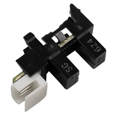
| Деталь: | Датчик выхода бумаги из узла термозакрепления |
| Парткод: | 130E87090 |
| Цена: | 1 700 ₽ |
| Деталь: | Датчик выхода бумаги из узла термозакрепления, в сборе |
| Парткод: | 604K71430 |
| Цена: | 3 700 ₽ |
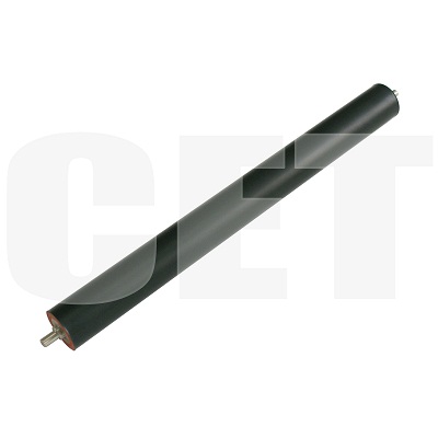
| Деталь: | Прижимной вал |
| Парткод: | CET4306 |
| Цена: | 1 500 ₽ |
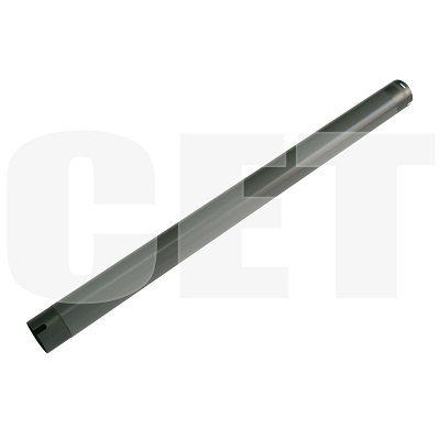
| Деталь: | Тефлоновый вал |
| Парткод: | CET4305 |
| Цена: | 2 200 ₽ |

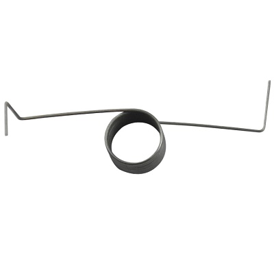
| Деталь: | Палец отделения бумаги от тефлонового вала |
| Парткод: | CET3525 |
| Деталь: | Пружина датчика выхода бумаги из узла термозакрепления |
| Парткод: | 809E42201 |
| Цена: | 170 ₽ |
| Деталь: | Датчик узла регистрации |
| Парткод: | 130K64270 |
| Цена: | 1 400 ₽ |
| Деталь: | Блок лазера |
| Парткод: | 062K13585 |
| Цена: | 62 500 ₽ |
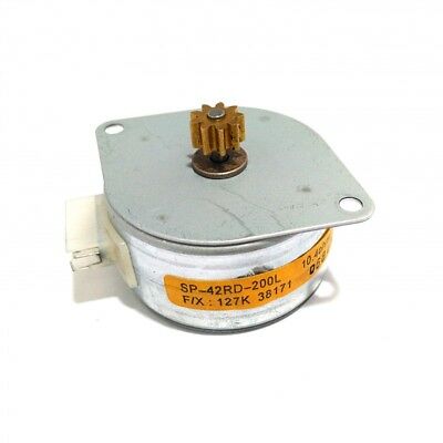
| Деталь: | Мотор подъёма в узле подачи бумаги |
| Парткод: | 127K38171 |
| Цена: | 5 400 ₽ |
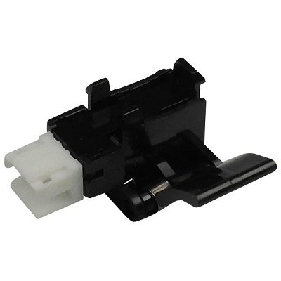
| Деталь: | Переключатель левой крышки |
| Парткод: | 110E94770 |
| Цена: | 1 700 ₽ |
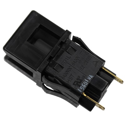
| Деталь: | Блокировочный переключатель |
| Парткод: | 110K11810 |
| Цена: | 1 500 ₽ |
| Деталь: | Плата контроля температуры |
| Парткод: | 130K87980 |
| Цена: | 2 500 ₽ |
| Деталь: | Мотор подачи тонера |
| Парткод: | 127K38040 |
| Цена: | 4 700 ₽ |
| Деталь: | Плата датчика контроля тонер-картриджа |
| Парткод: | 160K95834 |
| Цена: | 3 400 ₽ |
| Деталь: | Вентилятор узла термозакрепления |
| Парткод: | 127K37881 |
| Цена: | 10 000 ₽ |
| Деталь: | Мотор |
| Парткод: | 127K57201 |
| Цена: | 2 200 ₽ |
| Деталь: | Переключатель |
| Парткод: | 110E11580 |
| Цена: | 1 700 ₽ |
| Деталь: | Соленоид |
| Парткод: | 121K32370 |
| Цена: | 1 500 ₽ |
| Деталь: | Соленоид |
| Парткод: | 121K41701 |
| Цена: | 1 600 ₽ |
| Деталь: | Мотор |
| Парткод: | 127K51680 |
| Цена: | 3 500 ₽ |
| Деталь: | Узел вторичного переноса |
| Парткод: | 802K81270 |
| Цена: | 6 600 ₽ |
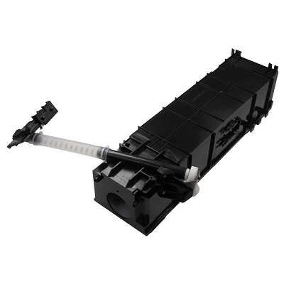
| Деталь: | Узел подачи тонера, в сборе |
| Парткод: | 032K96951 |
| Цена: | 5 400 ₽ |
| Деталь: | Направляющая бумаги в узле регистрации |
| Парткод: | 054K23940 |
| Цена: | 2 000 ₽ |
| Деталь: | Подшипник |
| Парткод: | 013E26060 |
| Цена: | 200 ₽ |
| Деталь: | Датчик |
| Парткод: | 930W00123 |
| Цена: | 750 ₽ |
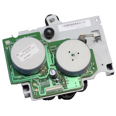
| Деталь: | Главный привод |
| Парткод: | 007K88585 |
| Цена: | 38 400 ₽ |
| Деталь: | Фланец в узле привода |
| Парткод: | 005E17860 |
| Цена: | 370 ₽ |
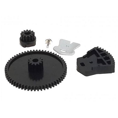
| Деталь: | Комплект шестерней главного редуктора |
| Парткод: | 604K20500 |
| Цена: | 2 100 ₽ |
| Деталь: | Стопор лотка |
| Парткод: | 003E61510 |
| Цена: | 2 800 ₽ |
| Деталь: | Переключатель формата бумаги |
| Парткод: | 110K12100 |
| Цена: | 1 500 ₽ |
| Деталь: | Направляющая в узле подачи бумаги |
| Парткод: | 054K24092 |
| Цена: | 1 100 ₽ |
| Деталь: | Вентилятор блока лазера |
| Парткод: | 927W00111 |
| Цена: | 2 400 ₽ |
| Деталь: | Направляюшая узла подачи бумаги |
| Парткод: | 054E25722 |
| Цена: | 2 600 ₽ |
| Деталь: | Направляющая вертикальной подачи бумаги |
| Парткод: | 054K24055 |
| Цена: | 9 000 ₽ |
| Деталь: | Шестерня |
| Парткод: | 007E79270 |
| Цена: | 400 ₽ |
| Деталь: | Подшипник вала вертикальной подачи бумаги |
| Парткод: | 013E29830 |
| Цена: | 600 ₽ |
| Деталь: | Комплект шестерней узла подъёма в кассете |
| Парткод: | 604K20543 |
| Цена: | 850 ₽ |
| Деталь: | Флажок датчика наличия бумаги в кассете |
| Парткод: | 120E22481 |
| Цена: | 2 600 ₽ |
| Деталь: | Держатель кабеля в узле подачи бумаги |
| Парткод: | 113E37571 |
| Деталь: | Кабель в узле подачи бумаги |
| Парткод: | 962K19692 |
| Цена: | 2 200 ₽ |
| Деталь: | Подшипник |
| Парткод: | 013E26091 |
| Цена: | 170 ₽ |
| Деталь: | Шестерня |
| Парткод: | 007E79320 |
| Цена: | 210 ₽ |
| Деталь: | Вал протяжки узла вертикальной подачи |
| Парткод: | 059K26840 |
| Цена: | 1 000 ₽ |
| Деталь: | Вспомогательный ролик в узле вертикальной подачи |
| Парткод: | 059E98371 |
| Цена: | 600 ₽ |
| Деталь: | Провод с разъёмом |
| Парткод: | 802K49240 |
| Цена: | 750 ₽ |
| Деталь: | Жгут проводов |
| Парткод: | 962K13060 |
| Цена: | 3 000 ₽ |
| Деталь: | Шестерня |
| Парткод: | 807E01360 |
| Цена: | 360 ₽ |
| Деталь: | Держатель |
| Парткод: | 849E23310 |
| Деталь: | Датчик плотности бумаги |
| Парткод: | 036K91620 |
| Цена: | 750 ₽ |
| Деталь: | Узел выхода, в сборе |
| Парткод: | 059K55771 |
| Цена: | 12 400 ₽ |
| Деталь: | Подшипник |
| Парткод: | 013E25550 |
| Цена: | 210 ₽ |
| Деталь: | Подшипник |
| Парткод: | 013E30050 |
| Цена: | 320 ₽ |
| Деталь: | Направляющая в узле выхода бумаги |
| Парткод: | 050E19804 |
| Цена: | 10 200 ₽ |
| Деталь: | Держатель оси в узле выхода бумаги |
| Парткод: | 054E23844 |
| Цена: | 1 400 ₽ |
| Деталь: | Комплект из 2-х роликов узла выхода бумаги |
| Парткод: | 604K47020 |
| Цена: | 1 300 ₽ |
| Деталь: | Ось узла выхода бумаги |
| Парткод: | 059K26761 |
| Цена: | 1 200 ₽ |
| Деталь: | Комплект из 2-х пружин узла выхода бумаги |
| Парткод: | 604K20420 |
| Цена: | 170 ₽ |
| Деталь: | Провода узла выхода бумаги |
| Парткод: | 962K15241 |
| Цена: | 500 ₽ |
| Деталь: | Нейтрализатор |
| Парткод: | 105E12940 |
| Деталь: | Защёлка |
| Парткод: | 003E60161 |
| Цена: | 900 ₽ |
| Деталь: | Направляющая в узле выхода бумаги |
| Парткод: | 050E20010 |
| Цена: | 1 500 ₽ |
| Деталь: | Держатель защёлки в узле выхода бумаги |
| Парткод: | 054E24372 |
| Цена: | 3 100 ₽ |
| Деталь: | Пружина |
| Парткод: | 809E37170 |
| Цена: | 2 600 ₽ |
| Деталь: | Комплект из 2-х подшипников оси выхода бумаги |
| Парткод: | 604K20680 |
| Цена: | 600 ₽ |
| Деталь: | Держатель оси и роликов выхода бумаги |
| Парткод: | 054E24332 |
| Цена: | 1 300 ₽ |
| Деталь: | Шестерня |
| Парткод: | 807E00180 |
| Деталь: | Комплект из 2-х роликов узла выхода бумаги |
| Парткод: | 604K20690 |
| Цена: | 480 ₽ |
| Деталь: | Комплект из 2-х пружин узла выхода бумаги |
| Парткод: | 604K20700 |
| Цена: | 170 ₽ |
| Деталь: | Защёлка |
| Парткод: | 003E60171 |
| Цена: | 750 ₽ |
| Деталь: | Пружина защёлки |
| Парткод: | 809E50210 |
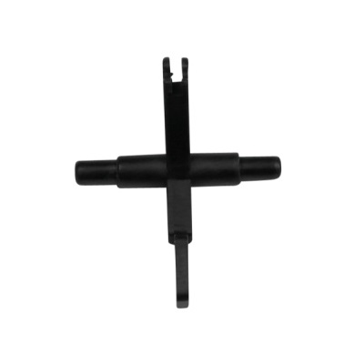
| Деталь: | Флажок датчика выхода бумаги |
| Парткод: | 120E22451 |
| Цена: | 340 ₽ |
| Деталь: | Комплект из 2-х пружин узла протяжки бумаги |
| Парткод: | 604K20430 |
| Цена: | 480 ₽ |
| Деталь: | Комплект из 2-х роликов узла протяжки бумаги |
| Парткод: | 604K20400 |
| Цена: | 600 ₽ |
| Деталь: | Флажок датчика |
| Парткод: | 059E98780 |
| Цена: | 330 ₽ |
| Деталь: | Пружина флажка датчика |
| Парткод: | 809E37332 |
| Цена: | 2 500 ₽ |
| Деталь: | Жгут проводов |
| Парткод: | 962K18882 |
| Цена: | 5 000 ₽ |
| Деталь: | Комплект из 4-х роликов узла протяжки бумаги |
| Парткод: | 604K20450 |
| Цена: | 500 ₽ |
| Деталь: | Пружина в узле протяжки бумаги |
| Парткод: | 809E54971 |
| Цена: | 410 ₽ |
| Деталь: | Жгут проводов |
| Парткод: | 962K13120 |
| Цена: | 500 ₽ |
| Деталь: | Комплект из 2-х вспомогательных роликов протяжки в лотке ручной подачи |
| Парткод: | 604K20410 |
| Деталь: | Флажок датчика |
| Парткод: | 120E22231 |
| Цена: | 9 800 ₽ |
| Деталь: | Шестерня |
| Парткод: | 007E79710 |
| Цена: | 330 ₽ |
| Деталь: | Накладка площадки отделения бумаги из кассеты и лотка ручной подачи |
| Парткод: | 019K09420 |
| Цена: | 4 000 ₽ |
| Деталь: | Ролик подачи бумаги из лотка ручной подачи |
| Парткод: | 059K40654 |
| Цена: | 1 400 ₽ |
| Деталь: | Муфта узла регистрации |
| Парткод: | 121K32660 |
| Цена: | 2 200 ₽ |
| Деталь: | Узел подачи бумаги из кассеты, в сборе |
| Парткод: | 059K42525 |
| Цена: | 16 900 ₽ |
| Деталь: | Комплект роликов захвата / подачи бумаги из кассеты |
| Парткод: | 604K20360 |
| Цена: | 5 900 ₽ |
| Деталь: | Привод нижнего узла регистрации, в сборе |
| Парткод: | 015K73511 |
| Цена: | 1 200 ₽ |
| Деталь: | Одноходовая муфта в узле подачи бумаги |
| Парткод: | 005K05890 |
| Цена: | 430 ₽ |
| Деталь: | Одноходовая шестерня в узле подачи бумаги |
| Парткод: | 005K06760 |
| Цена: | 3 600 ₽ |
| Деталь: | Муфта ролика отделения в узле подачи бумаги |
| Парткод: | 005K81880 |
| Цена: | 4 100 ₽ |
| Деталь: | Направляющая в узле регистрации |
| Парткод: | 054K35391 |
| Цена: | 1 500 ₽ |
| Деталь: | Подшипник вала регистрации |
| Парткод: | 013E26760 |
| Цена: | 200 ₽ |
| Деталь: | Направляющая бумаги в узле регистрации |
| Парткод: | 054E23941 |
| Цена: | 1 300 ₽ |
| Деталь: | Вспомогательный ролик протяжки бумаги в узле регистрации |
| Парткод: | 059E98590 |
| Цена: | 460 ₽ |
| Деталь: | Вал регистрации |
| Парткод: | 059K31021 |
| Цена: | 2 600 ₽ |
| Деталь: | Электромагнитная муфта в узле регистрации |
| Парткод: | 121K32730 |
| Цена: | 2 700 ₽ |
| Деталь: | Кассета на 500 листов, в сборе (лоток 2, 3) |
| Парткод: | 050K61183 |
| Цена: | 25 800 ₽ |
| Деталь: | Ролик замедления бумаги |
| Парткод: | 059K26591 |
| Цена: | 6 300 ₽ |
| Деталь: | PULLEY FEED |
| Парткод: | 059K26691 |
| Цена: | 4 400 ₽ |
| Деталь: | Подталкивающий ролик |
| Парткод: | 059K26702 |
| Цена: | 950 ₽ |
| Деталь: | Duplexing-feed assembly |
| Парткод: | 059K55760 |
| Цена: | 25 800 ₽ |
| Деталь: | Подшипник вала вертикальной подачи бумаги (правый) |
| Парткод: | 013E30110 |
| Цена: | 340 ₽ |
| Деталь: | Imaging high-voltage PCA |
| Парткод: | 105E17880 |
| Цена: | 900 ₽ |
| Деталь: | Модуль памяти (256MB) |
| Парткод: | 497K03680 |
| Цена: | 21 000 ₽ |
| Деталь: | Печь, в сборе (220В) |
| Парткод: | 126K24993 |
| Цена: | 31 700 ₽ |
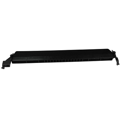
| Деталь: | Лоток ручной подачи бумаги, в сборе |
| Парткод: | 050K56601 |
| Цена: | 15 200 ₽ |
| Деталь: | Комплект маркировки лотков подачи бумаги |
| Парткод: | 604K20550 |
| Деталь: | Нижняя крышка в узле вертикальной подачи |
| Парткод: | 802E55701 |
| Цена: | 5 200 ₽ |
| Деталь: | Направляющая / держатель крышки узла вторичного переноса |
| Парткод: | 012K94341 |
| Цена: | 800 ₽ |
| Деталь: | Боковая крышка |
| Парткод: | 802K88891 |
| Цена: | 20 100 ₽ |
| Деталь: | Ручка кассеты |
| Парткод: | 003E59833 |
| Цена: | 650 ₽ |
| Деталь: | Направляющая |
| Парткод: | 054E23951 |
| Цена: | 1 600 ₽ |
| Деталь: | Направляющая |
| Парткод: | 054K30770 |
| Цена: | 800 ₽ |
| Деталь: | Крышка узла транспортировки, в сборе |
| Парткод: | 802K86923 |
| Цена: | 10 200 ₽ |
| Деталь: | Держатель левой крышки |
| Парткод: | 849E13981 |
| Цена: | 200 ₽ |
| Деталь: | Кассета для подачи конвертов |
| Парткод: | 050K61320 |
| Цена: | 39 600 ₽ |
| Деталь: | Узел выхода бумаги |
| Парткод: | 059K55870 |
| Цена: | 31 100 ₽ |
| Деталь: | Узел выхода бумаги |
| Парткод: | 059K55880 |
| Цена: | 21 000 ₽ |
| Деталь: | Направляющая в узле выхода бумаги |
| Парткод: | 038E26725 |
| Цена: | 1 400 ₽ |
| Деталь: | Передняя крышка лотка ручной подачи бумаги |
| Парткод: | 802E55201 |
| Цена: | 900 ₽ |
| Деталь: | Задняя крышка лотка ручной подачи бумаги |
| Парткод: | 802E55212 |
| Цена: | 1 000 ₽ |
| Деталь: | Информационные наклейки лотка ручной подачи бумаги |
| Парткод: | 604K20520 |
| Цена: | 1 500 ₽ |
| Деталь: | Узел лотка ручной подачи бумаги, в сборе |
| Парткод: | 801K30722 |
| Цена: | 5 100 ₽ |
Коды ошибок
003-318
003-319
003-320
005-121
005-122
005-123
005-125
005-131
005-132
005-134
005-135
005-136
005-139
005-145
005-146
005-147
005-194
005-196
005-197
005-198
005-199
005-275
005-280
005-284
005-285
005-286
005-305
005-306
005-309
005-500
005-906
005-907
005-908
005-909
005-910
005-911
005-912
005-913
005-914
005-915
005-916
005-917
005-918
005-919
005-942
010-313
010-314
010-318
010-320
010-327
010-398
010-420
010-421
012-111
012-112
012-126
012-131
012-132
012-151
012-152
012-161
012-211
012-212
012-213
012-221
012-223
012-224
012-231
012-243
012-249
012-259
012-260
012-263
012-265
012-268
012-269
012-280
012-282
012-283
012-284
012-291
012-295
012-296
012-300
012-301
012-302
012-303
012-901
012-903
012-905
012-923
012-935
012-949
013-210
013-211
013-212
013-213
013-220
013-306
013-307
024-362
024-363
024-364
024-910
024-911
024-912
024-913
024-914
024-915
024-916
024-917
024-928
024-930
024-946
024-949
024-950
024-951
024-952
024-953
024-954
024-955
024-958
024-959
024-960
024-961
024-962
024-965
024-966
024-967
024-976
024-977
024-978
024-979
024-980
024-981
024-982
024-984
024-985
024-989
027-742
042-323
042-325
047-211
047-213
047-214
047-215
047-216
047-217
061-315
061-321
061-333
062-211
062-277
062-300
062-310
062-311
062-345
062-357
062-360
062-371
062-380
062-386
062-389
062-392
062-393
062-500
062-790
071-105
071-210
071-211
071-940
072-101
072-105
072-210
072-211
073-101
073-102
073-105
073-210
073-211
074-101
074-102
074-103
074-105
074-210
074-211
075-135
077-101
077-103
077-104
077-106
077-109
077-113
077-114
077-129
077-130
077-131
077-211
077-300
077-301
077-305
077-307
077-308
077-309
077-310
077-329
078-101
078-102
078-104
078-210
078-212
078-300
078-301
078-900
078-940
078-941
078-945
078-946
091-402
091-441
091-910
091-911
091-912
091-913
091-914
091-915
091-916
092-661
092-662
093-400
093-406
093-912
093-924
093-925
093-926
094-417
094-420
102-356
102-380
102-381
102-382
Описание
| Error code: | 003-318 |
| Description: | IIT Software RAP. |
| Remedy: | • Ensure that the customer is programming a job within the parameters of the machine utilizing the UI. • Disconnect then reconnect the IIT, Control Panel, ESS, MCU all PWBs connected to them (RAM, Firmware module, EEPROM) • Check the sw version of the controller sw • Reload Software (GP 16) • Replace IIT PWB (Switch the EEPROM) (PL 1.6) • If the problem persists, replace the ESS PWB (PL 35.2). (If not fixed by this, reinstall the original ESS PWB and RAM DIMM.) |
| Error code: | 003-319 |
| Description: | IIT Video Driver Detection RAP One of the following errors is detected: • Compression Threshold overflow • DMA Transfer error • Other system compression errors |
| Remedy: | • Ensure that the customer is programming a job within the parameters of the machine utilizing the UI. • Disconnect then reconnect the IIT, Control Panel, ESS, MCU all PWBs connected to them (RAM, Firmware module, EEPROM) • Reload Software (GP 16) • Replace IIT PWB (Switch the EEPROM) (PL 1.6) • If the problem persists, replace the ESS PWB (PL 35.2). (If not fixed by this, reinstall the original ESS PWB and RAM DIMM.) |
| Error code: | 003-320 |
| Description: | IISS-ESS Communication 1 RAP An abnormal parameter is set as the argument for the send function. After avoiding detection condition of 116-389 at power on, extended memory capacity in document scanning area below 256MB is detected with IITsc-detected Fault Code, while Fax Card is mounted. |
| Remedy: | • Disconnect and reconnect the IIT Harness (PL 1.6). • Reload Software (GP 16). • If the problem persists, replace the IIT PWB (Switch the EEPROM) (PL 1.6). |
| Error code: | 005-121 |
| Display: | Paper Jam 005-121 Open ADF Cover and Clear Jam |
| Description: | ADF JAM Detect ADFJAM |
| Causes: | • DADF Assembly (PL51.1.2) • IIT Pick-up Module Kit (PL51.1.4) • IP Board (PL18.1.22) |
| Remedy: | 1 Check the document Does the document meet the specifications of the printer? Go to step 2. Use the right document. 2 Check the DADF Assembly Is the DADF Assembly closed properly against the platen glass? Go to step 3. Close the DADF Assembly properly. 3 Check the DADF Assembly connection Check the connection between the DADF Assembly and the IP Board. Is P/J1502 connected securely? Go to step 4. Connect P/J1502 securely. 4 Check the document path Open the DADF cover and check the document path. Are there any foreign objects, or paper pieces, etc. on the document path? Remove the foreign objects, or paper pieces, etc. Go to step 5. 5 Check the IIT Pick-up Module Kit Is the IIT Pick-up Module Kit installed properly? Go to step 3. Reinstall the IIT Pick-up Module Kit. 6 Check the IIT Pick-up Module Kit Is the IIT Pick-up Module Kit deformed or worn out? Replace the KIT IIT Pick-up Module. Go to step 7. 7 Check after replacing the DADF Assembly Replace the DADF Assembly. Does the error still occur? Replace the IP Board. Finished. |
| Error code: | 005-122 |
| Description: | DADF Simplex/Side 1 Pre Registration Sensor On Jam RAP • After Pre-Feed started for the first sheet (DADF Feed Motor On (CW)) in Simplex and Duplex, the DADF Pre Registration Sensor did not turn ON within the specified time. • After Pre-Feed started for the second sheet onwards (DADF Feed Motor On (CW)) in Duplex, the DADF Pre Registration Sensor did not turn ON within the specified time. |
| Remedy: | Open the Top Cover and remove the Invert Chute. Enter the Diag Mode, turn ON Component Control [005-206]. Block the DADF Pre Registration Sensor using a sheet of paper, etc. Does the display change to High? Y↓N→Disconnect the DADF Pre Registration Sensor connector P/J774. Does the display change to High? Y↓N→Check the wire between the DADF Pre Registration Sensor P/J774-2 and the DADF PWB P/J757-11 for a short circuit. If no problems are found, replace the DADF PWB (PL 51.2). Is the voltage between P/J774-1 (+) and P/J774-3 (-) +5VDC? Y↓N→Check the wires between the DADF PWB P/J757-12 and the DADF Pre Registration Sensor P/J774-1, as well as between the DADF PWB P/J757-10 and the DADF Pre Registration Sensor P/J774-3 for open circuits and poor contacts. Replace the DADF Pre Registration Sensor (PL 51.17). Press the Stop button. Turn ON Component Control [005-010] (DADF Feed Motor). Does the DADF Feed Motor operate? Y↓N→Is the voltage between the DADF Feed Motor P/J776-5/2 (+) and the GND (-) +24VDC? Y↓N→Is the voltage between the DADF PWB P/J754-B1/B2 (+) and the GND (-) +24VDC? Y↓N→Is the voltage between the DADF PWB P/J753-2 (+) and the GND (-) +24VDC? Y↓N→Refer to BSD 5.1 - Document Setting and check the +24VDC circuit to the DADF PWB P/J753-2. Replace the DADF PWB (PL 51.2). Check the wires between the DADF PWB P/J754-B1 and the DADF Feed Motor P/ J776-5, as well as between the DADF PWB P/J754-B2 and the DADF Feed Motor P/J776-2 for an open circuit and poor contact. Turn OFF the power and disconnect P/J754 from the DADF PWB. Measure the wire wound resistance of the Motor. • Between P/J754 pin-B1 and P/J754 pin-B5/B6 • Between P/J754 pin-B2 and P/J754 pin-B3/B4 Is the resistance approximately. 1Ohm for each? Y↓N→Replace the DADF Feed Motor (PL 51.5). Replace the DADF PWB (PL 51.2). Check the following: • The document path for foreign substances. • Overly strong Retard pressure. • The DADF Pre Registration Sensor Actuator for disengagement, drag and damage. |
| Error code: | 005-123 |
| Description: | DADF Simplex/Side 1 Registration Sensor On Jam RAP After Pre Registration operation started (DADF Feed Motor On (CCW)), the DADF Registration Sensor did not turn ON within the specified time. |
| Remedy: | Open the Top Cover and remove the Invert Chute. Enter the Diag Mode, turn ON Component Control [005-110]. Turn ON the DADF Registration Sensor using a sheet of paper, etc. Does the display change to "H" (opposite to the voltage level)? Y↓N→Remove the DADF Rear Cover. Is the voltage between the DADF PWB P/J757-14 (+) and the GND (-) +5VDC? Y↓N→Replace the DADF PWB (PL 51.2). The voltage between the DADF Registration Sensor P/J775-2 (+) and the GND (-) +5VDC? Y↓N→Check the connection between the DADF Registration Sensor P/J775-2 and the DADF PWB P/J757-14 for an open circuit and poor contact. The voltage between the DADF Registration Sensor P/J775-1 (+) and P/J775-3 (-) +5VDC? Y↓N→Check the wires between the DADF PWB P/J757-15 and the DADF Registration Sensor P/J775-1, as well as between the DADF PWB P/J757-13 and the DADF Registration Sensor P/J775-3 for open circuits and poor contacts. Replace the DADF Registration Sensor (PL 51.17). Press the Stop button. Turn ON Component Control [005-008] (DADF Feed Motor). Does the DADF Feed Motor operate? Y↓N→The voltage between the DADF Feed Motor P/J776-5/2 (+) and the GND (-) +24VDC? Y↓N→The voltage between the DADF PWB P/J754-B1/B2 (+) and the GND (-) +24VDC? Y↓N→The voltage between the DADF PWB P/J753-2 (+) and the GND (-) +24VDC? Y↓N→Refer to BSD 5.1 - Document Setting and check the +24VDC circuit to the DADF PWB P/J753-2. Replace the DADF PWB (PL 51.2). Check the wires between the DADF PWB P/J754-B1 and the DADF Feed Motor P/ J776-5, as well as between the DADF PWB P/J754-B2 and the DADF Feed Motor P/J776-2 for an open circuit and poor contact. Turn OFF the power and disconnect P/J754 from the DADF PWB. Measure the wire wound resistance of the Motor. • Between P/J754 pin-B1 and P/J754 pin-B5/B6 • Between P/J754 pin-B2 and P/J754 pin-B3/B4 The resistance approximately 1Ohm for each? Y↓N→Replace the DADF Feed Motor (PL 51.5). Replace the DADF PWB (PL 51.2). Check the following: • The document path for foreign substances. • The Transportation Roll for contamination, wear or revolution failure. |
| Error code: | 005-125 |
| Description: | DADF Registration Sensor Off Jam RAP After the DADF Pre Registration Sensor turned OFF, the DADF Registration Sensor did not turn OFF within the specified time. |
| Remedy: | Check the following: • Transportation failure due to foreign substance in the document path • The surface of the roll for foreign substance • The surface of the roll for wear • Check the sw version of the controller sw - update if required. • DADF Feed Motor: Component Control [005-008] (PL 51.5) • DADF Registration Motor: Component Control [005-033] (PL 51.5) • Check the circuit between the DADF Registration Sensor and the DADF PWB • Check the circuit between the DADF Pre Registration Sensor and the DADF PWB • DADF Registration Sensor: Component Control [005-110] (PL 51.17) • DADF Pre Registration Sensor: Component Control [005-206] (PL 51.17) • DADF PWB failure. (PL 51.2) |
| Error code: | 005-131 |
| Description: | DADF Invert Sensor On Jam (During Invert) RAP After the DADF Registration Sensor turned ON at Invert, the DADF Invert Sensor did not turn ON within the specified time. |
| Remedy: | Check the following: • Transportation failure due to foreign substance in the document path • The surface of the roll for foreign substance • The surface of the roll for wear • Check the sw version of the controller sw - update if required. • DADF Registration Motor: Component Control [005-033] (PL 51.5) • Check the circuit between the DADF Registration Sensor and the DADF PWB • Check the circuit between the DADF Inverter Sensor and the DADF PWB • DADF Registration Sensor: Component Control [005-110] (PL 51.17) • DADF Invert Sensor: Component Control [005-211] (PL 51.9) • DADF PWB failure. (PL 51.2) |
| Error code: | 005-132 |
| Description: | DADF Invert Sensor On Jam RAP After the Read Speed Control operation started (DADF Registration Motor On (CCW)), the DADF Invert Sensor did not turn ON within the specified time. |
| Remedy: | Check the following: • Transportation failure due to foreign substance in the document path • The surface of the roll for foreign substance • The surface of the roll for wear • Check the sw version of the controller sw - update if required. • DADF Registration Motor: Component Control [005-033] (PL 51.5) • Check the circuit between the DADF Inverter Sensor and the DADF PWB • DADF Invert Sensor: Component Control [005-211] (PL 51.9) • DADF PWB failure. (PL 51.2) |
| Error code: | 005-134 |
| Description: | DADF Inverter Sensor Off Jam (During Invert) RAP • After the DADF Registration Sensor turned OFF at Invert of the last document, the DADF Inverter Sensor did not turn OFF within the specified time. • During the Invert where there is a next document, after the Read Speed Control operation started (DADF Registration Motor On (CCW)), the DADF Inverter Sensor did not turn OFF within the specified time. |
| Remedy: | Check the following: • Transportation failure due to foreign substance in the document path • The surface of the roll for foreign substance • The surface of the roll for wear • Check the sw version of the controller sw - update if required. • DADF Registration Motor: Component Control [005-033] (PL 51.5) • Check the circuit between the DADF Registration Sensor and the DADF PWB • Check the circuit between the DADF Inverter Sensor and the DADF PWB • DADF Registration Sensor: Component Control [005-110] (PL 51.17) • DADF Invert Sensor: Component Control [005-211] (PL 51.9) • DADF PWB failure. (PL 51.2) |
| Error code: | 005-135 |
| Description: | DADF Side 2 Pre Registration Sensor On Jam RAP After the Invert operation started (DADF Registration Motor On (CW)) at Invert, the DADF Pre Registration Sensor did not turn ON within the specified time. |
| Remedy: | Check the following: • Transportation failure due to foreign substance in the document path • The surface of the roll for foreign substance • The surface of the roll for wear • Check the sw version of the controller sw - update if required. • DADF Registration Motor: Component Control [005-033] (PL 51.5) • Check the circuit between the DADF Pre Registration Sensor and the DADF PWB • DADF Pre Registration Sensor: Component Control [005-206] (PL 51.17) • DADF PWB failure. (PL 51.2) • The Gate Solenoid Component Control [005-090] for operation failure • Check if the Exit Roll is nipping properly. (Including the operations of Exit Nip Release Solenoid (Component Control [005-072])) (PL 51.6). |
| Error code: | 005-136 |
| Description: | DADF Side 2 Registration Sensor On Jam RAP After the DADF Pre Registration Sensor turned ON at Invert, the DADF Registration Sensor did not turn ON within the specified time. |
| Remedy: | Check the following: • Transportation failure due to foreign substance in the document path • The surface of the roll for foreign substance • The surface of the roll for wear • Check the sw version of the controller sw - update if required. • Check if the Exit Roll is nipping properly. (Including the operations of Exit Nip Release Solenoid (Component Control [005-072])) (PL 51.6) • Check the circuit between the DADF Pre Registration Sensor and the DADF PWB • DADF Pre Registration Sensor: Component Control [005-206] (PL 51.17) • Check the circuit between the DADF Registration Sensor and the DADF PWB • DADF Registration Sensor: Component Control [005-110] (PL 51.17) • DADF Feed Motor: Component Control [005-008] (PL 51.5) • DADF PWB failure. (PL 51.2) |
| Error code: | 005-139 |
| Description: | DADF Invert Sensor Off Jam RAP • After the DADF Registration Sensor turned OFF in the Scan operation, the DADF Invert Sensor did not turn OFF within the specified time. • During the 1 Sided mode scan operation where there is a next document, after the Next Document Scan Read Speed Control started (DADF Registration Motor On (CCW)), the DADF Inverter Sensor did not turn OFF within the specified time. |
| Remedy: | Check the following: • Transportation failure due to foreign substance in the document path • The surface of the roll for foreign substance • The surface of the roll for wear • Check the sw version of the controller sw - update if required. • The Gate Solenoid Component Control [005-090] for operation failure • DADF Registration Motor: Component Control [005-033] (PL 51.5) • Check if the Exit Roll is nipping properly. (Including the operations of Exit Nip Release Solenoid (Component Control [005-072])) (PL 51.6) • Check the circuit between the DADF Registration Sensor and the DADF PWB • DADF Registration Sensor: Component Control [005-110] (PL 51.17) • Check the circuit between the DADF Inverter Sensor and the DADF PWB • DADF Invert Sensor: Component Control [005-211] (PL 51.9) • DADF PWB failure. (PL 51.2) |
| Error code: | 005-145 |
| Description: | DADF Registration Sensor Off Jam (Invert) RAP After the DADF Pre Registration Sensor turned OFF at Invert, the DADF Registration Sensor did not turn OFF within the specified time. |
| Remedy: | Check the following: • Transportation failure due to foreign substance in the document path • The surface of the roll for foreign substance • The surface of the roll for wear • Check the sw version of the controller sw - update if required. • DADF Registration Motor: Component Control [005-033] (PL 51.5) • DADF Feed Motor: Component Control [005-008] (PL 51.5) • Check the circuit between the DADF Registration Sensor and the DADF PWB • DADF Registration Sensor: Component Control [005-110] (PL 51.17) • Check the circuit between the DADF Pre Registration Sensor and the DADF PWB • DADF Pre Registration Sensor: Component Control [005-206] (PL 51.17) • DADF PWB failure. (PL 51.2) |
| Error code: | 005-146 |
| Description: | DADF Pre Registration Sensor Off Jam RAP After the DADF Feed Out Sensor turned OFF in 1 Sided mode, the DADF Pre Registration Sensor did not turn OFF within the specified time. |
| Remedy: | Check the following: • Transportation failure due to foreign substance in the document path • The surface of the roll for foreign substance • The surface of the roll for wear • Check the sw version of the controller sw - update if required. • DADF Registration Motor: Component Control [005-033] (PL 51.5) • DADF Feed Motor: Component Control [005-010] (PL 51.5) • Check if the Exit Roll is nipping properly. (Including the operations of Exit Nip Release Solenoid (Component Control [005-072])) (PL 51.6) • Check the circuit between the DADF Pre Registration Sensor and the DADF PWB • DADF Pre Registration Sensor: Component Control [005-206] (PL 51.17) • DADF PWB failure. (PL 51.2) |
| Error code: | 005-147 |
| Description: | DADF Pre Registration Sensor Off Jam (Invert) RAP After the DADF Registration Motor turned ON at Invert, the DADF Pre Registration Sensor did not turn OFF within the specified time. |
| Remedy: | Check the following: • Transportation failure due to foreign substance in the document path • The surface of the roll for foreign substance • The surface of the roll for wear • Check the sw version of the controller sw - update if required. • DADF Registration Motor: Component Control [005-033] (PL 51.5) • DADF Feed Motor: Component Control [005-010] (PL 51.5) • Check the circuit between the DADF Pre Registration Sensor and the DADF PWB • DADF Pre Registration Sensor: Component Control [005-206] (PL 51.17) • DADF PWB failure. (PL 51.2) |
| Error code: | 005-194 |
| Description: | Size Mismatch Jam On SS Mix-Size RAP In Slow Scan (SS) Mixed mode, it was detected that the size in the Fast Scan Direction was different from the width of the document guide. |
| Remedy: | Check the following: • Check that the DADF Tray Set Guide operates normally. • Check the circuit between the DADF Tray Set Guide Sensors 1-3 and the DADF PWB • DADF Tray Set Guide Sensors 1-3: Component Control [005-215/216/217] (PL 51.10) |
| Error code: | 005-196 |
| Description: | Size Mismatch Jam On No Mix-Size RAP A document in a different size from the first document was detected in the No Mix mode. |
| Remedy: | Check the following: • DADF Tray Set Guide Sensors 1-3: Component Control [005-215/216/217] (PL 51.10) • DADF APS Sensor 1: Component Control [005-218] (PL 51.17) • Document Tray Size Sensor 1/2: Component Control [005-221/222] (PL 51.10) • Check the sw version of the controller sw - update if required (GP 16). • If no problems are found, replace the DADF PWB (PL 51.2). |
| Error code: | 005-197 |
| Description: | Prohibit Combine Size Jam RAP. A prohibited size combination was detected. |
| Remedy: | Explain to the customer that the following combinations are prohibited. • 5.5 x 8.5 SEF and all the other document sizes. • A5 SEF and all the other document sizes. • B5 SEF, plus 11 x 15 SEF, 11 x 17 SEF, A4 LEF, A3 LEF, 8.5 x 11 LEF. |
| Error code: | 005-198 |
| Description: | Too Short Size Jam RAP It was detected that the document length in Slow Scan direction was out of the specifications. • Simplex mode: shorter than 85mm • Duplex mode: shorter than 110mm |
| Remedy: | Check the document size a user has scanned. If its length is within the available range for DADF feeding, check the circuit between the DADF Pre Registration Sensor, the DADF Feed Out Sensor, and the DADF PWB. Check the sw version of the controller sw - update if required (GP 16). If no problems are found, replace the DADF PWB (PL 51.2). |
| Error code: | 005-199 |
| Description: | Too Long Size Jam RAP It was detected that the document length in Slow Scan direction was out of the specifications. • Simplex and Duplex modes: 431.9mm or longer • Fax mode: 1501.0mm or longer |
| Remedy: | Check the document size a user has scanned. If its length is within the available range for DADF feeding, check the circuit between the DADF Pre Registration Sensor, the DADF Feed Out Sensor, and the DADF PWB. Check the sw version of the controller sw - update if required (GP 16). If no problems are found, replace the DADF PWB (PL 51.2). |
| Error code: | 005-275 |
| Description: | DADF Error There is a processing error in the DADF PWB. |
| Remedy: | Switch off the power. Disconnect and reconnect the P/Js on the DADF PWB. Switch on the power. If the problem persists, replace the DADF PWB (PL 15.3). |
| Error code: | 005-280 |
| Description: | DADF EPROM Failure RAP The DADF-EEPROM failed during the Read/Write operation. |
| Remedy: | Check the connection of each DADF PWB connector. The connectors are connected correctly. Y↓N→Connect the connectors. Turn on the power again. [005-280] reoccurs. Y↓N→Return to Service Call Procedures. Replace the DADF PWB (PL 15.3). |
| Error code: | 005-284 |
| Description: | DADF Auto Paper Selection Sensor Logic Failure RAP The combinations of outputs from the DADF APS 1 Sensor, DADF APS 2 Sensor and DADF APS 3 Sensor are abnormal. |
| Remedy: | Execute Component Control[005-218]. Actuate the DADF APS 1 Sensor with paper. The display changes. Y↓N→Check the connections of P/J777 and P/J761. P/J777 and P/J761 are connected correctly. Y↓N→Connect P/J777 and P/J761. Check the wire between J777 and J761 for an open circuit or a short circuit. The wire between J777 and J761 is conducting without an open circuit or a short circuit. Y↓N→Repair the open circuit or short circuit. Measure the voltage between the DADF PWB P761-4 (+) and GND (-). The voltage is approx. +5VDC. Y↓N→Replace the DADF PWB (PL 15.3). Measure the voltage between the DADF PWB P761-6 (+) and GND (-). Actuate the DADF APS 1 Sensor with paper. The voltage changes. Y↓N→Replace the DADF APS 1 Sensor (PL 15.7). Replace the DADF PWB (PL 15.3). Execute Component Control[005-219]. Actuate the DADF APS 2 Sensor with paper. The display changes. Y↓N→Check the connections of P/J778 and P/J761. P/J778 and P/J761 are connected correctly. Y↓N→Connect P/J778 and P/J761. Check the wire between J778 and J761 for an open circuit or a short circuit. The wire between J778 and J761 is conducting without an open circuit or a short circuit. Y↓N→Repair the open circuit or short circuit. Measure the voltage between the DADF PWB P761-1 (+) and GND (-). The voltage is approx. +5VDC. Y↓N→Replace the DADF PWB (PL 15.3). Measure the voltage between the DADF PWB P761-3 (+) and GND (-). Actuate the DADF APS 2 Sensor with paper. The voltage changes. Y↓N→Replace the DADF APS 2 Sensor (PL 15.7). Replace the DADF PWB (PL 15.3). Execute Component Control[005-220]. Actuate the DADF APS 3 Sensor with paper. The display changes. Y↓N→Check the connections of P/J779 and P/J785. P/J779 and P/J785 are connected correctly. Y↓N→Connect P/J779 and P/J785. Check the wire between J779 and J785 for an open circuit or a short circuit. The wire between J779 and J785 is conducting without an open circuit or a short circuit. Y↓N→Repair the open circuit or short circuit. Measure the voltage between the DADF PWB P785-1 (+) and GND (-). The voltage is approx. +5VDC. Y↓N→Replace the DADF PWB (PL 15.3). Measure the voltage between the DADF PWB P785-3 (+) and GND (-). Actuate the DADF APS 3 Sensor with paper. The voltage changes. Y↓N→Replace the DADF APS 3 Sensor (PL 15.7). Replace the DADF PWB (PL 15.3). Replace the DADF PWB (PL 15.3). |
| Error code: | 005-285 |
| Description: | DADF Nudger Lift Up Failure RAP After the DADF Nudger Motor started reverse rotation, the DADF Nudger Sensor did not turn On within the specified time. |
| Remedy: | Manually operate the Feed Head mechanism. The Feed Head mechanism moves smoothly. Y↓N→Replace the parts that are interfering with operation. Execute Component Control[005-225]. Actuate the DADF Nudger Sensor with paper. The display changes. Y↓N→Check the connections of P/J788 and P/J786. P/J788 and P/J786 are connected correctly. Y↓N→Connect P/J788 and P/J786. Check the wire between J788 and J786 for an open circuit or a short circuit. The wire between J788 and J786 is conducting without an open circuit or a short circuit. Y↓N→Repair the open circuit or short circuit. Measure the voltage between the DADF PWB P786-7 (+) and GND (-). The voltage is approx. +5VDC. Y↓N→Replace the DADF PWB (PL 15.3). Measure the voltage between the DADF PWB P786-9 (+) and GND (-). Actuate the DADF Nudger Sensor with paper. The voltage changes. Y↓N→Replace the DADF Nudger Sensor (PL 15.5). Replace the DADF PWB (PL 15.3). Execute Component Control[005-090]. The DADF Nudger Motor (PL 15.6) can be heard. Y↓N→Check the connections of P/J787 and P/J786. P/J787 and P/J786 are connected correctly. Y↓N→Connect P/J787 and P/J786. Check the wire between J787 and J786 for an open circuit or a short circuit. The wire between J787 and J786 is conducting without an open circuit or a short circuit. Y↓N→Repair the open circuit or short circuit. Measure the voltage between the DADF PWB (PL 15.3) P786-1 (+) and GND (-). The voltage is approx. +24VDC. Y↓N→Replace the DADF PWB (PL 15.3). Replace the DADF Nudger Motor (PL 15.6). If the problem persists, replace the DADF PWB (PL 15.3). Replace the DADF PWB (PL 15.3). |
| Error code: | 005-286 |
| Description: | DADF Feed Out Sensor Failure RAP During document transport, before the DADF Feed Out Sensor turned Off, the DADF Pre Registration Sensor turned Off. |
| Remedy: | Execute Component Control[005-205]. Actuate the DADF Feed Out Sensor (PL 15.9) with paper. The display changes. Y↓N→Check the connections of P/J769 and P/J758. P/J769 and P/J758 are connected correctly. Y↓N→Connect P/J769 and P/J758. Check the wire between J769 and J758 for an open circuit or a short circuit. The wire between J769 and J758 is conducting without an open circuit or a short circuit. Y↓N→Repair the open circuit or short circuit. Measure the voltage between the DADF PWB P758-1 (+) and GND (-). The voltage is approx. +5VDC. Y↓N→Replace the DADF PWB (PL 15.3). Measure the voltage between the DADF PWB P758-3 (+) and GND (-). Actuate the DADF Feed Out Sensor with paper. The voltage changes. Y↓N→Replace the DADF Feed Out Sensor (PL 15.9). Replace the DADF PWB (PL 15.3). Execute Component Control [005-206]. Actuate the DADF Pre Registration Sensor (PL 15.7) with paper. The display changes. Y↓N→Check the connections of P/J781 and P/J761. P/J781 and P/J761 are connected correctly. Y↓N→Connect P/J781 and P/J761. Check the wire between J781 and J761 for an open circuit or a short circuit. The wire between J781 and J761 is conducting without an open circuit or a short circuit. Y↓N→Repair the open circuit or short circuit. Measure the voltage between the DADF PWB P761-10 (+) and GND (-). The voltage is approx. +5VDC. Y↓N→Replace the DADF PWB (PL 15.3). Measure the voltage between the DADF PWB P761-12 (+) and GND (-). Actuate the DADF Pre Registration Sensor with paper. The voltage changes. Y↓N→Replace the DADF Pre Registration Sensor (PL 15.7). Replace the DADF PWB (PL 15.3). Replace the DADF PWB (PL 15.3). |
| Error code: | 005-305 |
| Description: | DADF Feeder Cover Interlock Open (when running) RAP The Feeder Cover Interlock was opened during DADF operation. |
| Remedy: | Check the following: • The DADF Feeder Cover for misalignment or damage. • DADF Interlock Switch: Component Control [005-212] (PL 51.5) • Check the sw version of the controller sw - update if required • If the problem persists, check the circuit between the DADF Interlock Switch and the DADF PWB. If no problems are found, replace the DADF PWB (PL 51.2). |
| Error code: | 005-306 |
| Description: | Tray Interlock Open RAP Tray Interlock Open during DADF operation detected. |
| Remedy: | To ensure that the Tray is Closed. Check the connections between the Tray Interlock Sensor and the DADF PWB. If OK, replace the Tray Interlock Sensor. If the problem persists, replace the DADF PWB (PL 15.3). |
| Error code: | 005-309 |
| Description: | CVT L/H Interlock Open RAP CVT L/H Interlock Open while running. |
| Remedy: | Check the following: connector cables (connecting Interlock Switch and DADF-PWBA), or DADF-PWBA. • For damage to the cover, repair or replace Feeder Cover as required • Connector between the Interlock Switch and the DADF PWB, repair or replace as required • The Interlock Switch for alignment or damage, align or replace the L/H Interlock Switch as required |
| Error code: | 005-500 |
| Description: | Write to DADF-ROM Error RAP 005-500 An error has occurred during the process of writing data to the DADF-ROM. |
| Remedy: | 1. Reload the software, GP 4 2. Install a new DADF ASSY REP 50.1.1 |
| Error code: | 005-906 |
| Description: | DADF Feed Out Sensor Static Jam RAP The DADF Feed Out Sensor turns ON at the following timings. 1. When Power is ON 2. At Feeder Cover Interlock Close 3. At Platen Interlock Close |
| Remedy: | Check the following: • Check the DADF Feed Out Sensor for remaining paper, the Actuator for return failure, foreign substances, contamination on sensors, and etc. • DADF Feed Out Sensor: Component Control [005-205] (PL 51.6) • Check the sw version of the controller sw - update if required • If the problem persists, check the circuit between the DADF Feed Out Sensor and the DADF PWB. If no problems are found, replace the DADF PWB (PL 51.2). |
| Error code: | 005-907 |
| Description: | DADF Pre Registration Sensor Static Jam RAP The DADF Pre Registration Sensor turns ON at the following timings: 1. When Power is ON 2. At Feeder Cover Interlock Close 3. At Platen Interlock Close |
| Remedy: | Check the following: • Check the DADF Pre Registration Sensor for remaining paper, the Actuator for return failure, foreign substances, contamination on sensors, and etc. • DADF Pre Registration Sensor: Component Control [005-206] (PL 51.17) • Check the sw version of the controller sw - update if required • If the problem persists, check the circuit between the DADF Pre Registration Sensor and the DADF PWB. If no problems are found, replace the DADF PWB (PL 51.2). |
| Error code: | 005-908 |
| Description: | CVT Registration Sensor Static JAM RAP Paper remains on the DADF Registration Sensor. |
| Remedy: | Execute Component Control[005-110 DADF Registration Sensor]. Actuate the DADF Registration Sensor (PL 15.7) with paper. The display changes. Y↓N→Check the connections of P/J782 and P/J761. P/J782 and P/J761 are connected correctly. Y↓N→Connect P/J782 and P/J761. Check the wire between J782 and J761 for an open circuit or a short circuit. The wire between J782 and J761 is conducting without an open circuit or a short circuit. Y↓N→Repair the open circuit or short circuit. Measure the voltage between the DADF PWB P761-15 (+) and GND (-). The voltage is approx. +5VDC. Y↓N→Replace the DADF PWB (PL 15.3). Measure the voltage between the DADF PWB P761-14 (+) and GND (-). Actuate the DADF Registration Sensor with paper. The voltage changes. Y↓N→Replace the DADF Registration Sensor (PL 15.7). Replace the DADF PWB (PL 15.3). Replace the DADF PWB (PL 15.3). |
| Error code: | 005-909 |
| Description: | DADF Lead Sensor Static Jam Lead Reg Sensor On detected at the timing below: 1. Power On 2. Feeder Cover Interlock Close 3. Platen Interlock Close. |
| Remedy: | If the problem occurs frequently, make sure that there is no obstacle blocking the light path on Lead Reg Sensor. Check the connections between the Lead Reg Sensor and the DADF PWB. If OK, replace the Lead Reg Sensor. If the problem persists, replace the DADF PWB (PL 15.3). |
| Error code: | 005-910 |
| Description: | DADF Out Sensor Static Jam Out Sensor On detected at the timing below: 1. Power On 2. Feeder Cover Interlock Close 3. Platen Interlock Close. |
| Remedy: | If the problem occurs frequently, make sure that there is no obstacle blocking the light path on Out Sensor. Check the connections between the Out Sensor and the DADF PWB. If OK, replace the Out Sensor. If the problem persists, replace the DADF PWB (PL 15.3). |
| Error code: | 005-911 |
| Description: | DADF Exit 1 Sensor Static Jam Exit1 Sensor On detected at the timing below: 1. Power On 2. Feeder Cover Interlock Close 3. Platen Interlock Close. |
| Remedy: | If the problem occurs frequently, make sure that there is no obstacle blocking the light path on Exit1 Sensor. Check the connections between the Exit1 Sensor and the DADF PWB. If OK, replace the Exit1 Sensor. If the problem persists, replace the DADF PWB (PL 15.3). |
| Error code: | 005-912 |
| Description: | DADF Exit 2 Sensor Static Jam Exit2 Sensor On detected at the timing below: 1. Power On 2. Feeder Cover Interlock Close 3. Platen Interlock Close. |
| Remedy: | If the problem occurs frequently, make sure that there is no obstacle blocking the light path on Exit2 Sensor. Check the connections between the Exit2 Sensor and the DADF PWB. If OK, replace the Exit2 Sensor. If the problem persists, replace the DADF PWB (PL 15.3). |
| Error code: | 005-913 |
| Description: | DADF Inverter Sensor Static Jam RAP The DADF Invert Sensor turns On at the timings below. 1. When Power is ON 2. At Feeder Cover Interlock Close 3. At Platen Interlock Close |
| Remedy: | Check the following: • Check the DADF Inverter Sensor for remaining paper, the Actuator for return failure, foreign substances, contamination on sensors, and etc. • DADF Invert Sensor: Component Control [005-211] (PL 51.9) • Check the sw version of the controller sw - update if required • If the problem persists, check the circuit between the DADF Invert Sensor and the DADF PWB. If no problems are found, replace the DADF PWB (PL 51.2). |
| Error code: | 005-914 |
| Description: | DADF APS1, 2, 3, Sensor Static Jam APS1, 2, 3, Sensor On detected at the timing below: 1. Power On 2. Feeder Cover Interlock Close 3. Platen Interlock Close. |
| Remedy: | If the problem occurs frequently, make sure that there is no obstacle blocking the light path on APS1, 2, 3, Sensor. Check the connections between the APS1, 2, 3, Sensor and the DADF PWB. If OK, replace the APS1, 2, 3, Sensor. If the problem persists, replace the DADF PWB (PL 15.3). |
| Error code: | 005-915 |
| Description: | DADF APS Sensor 1 Static Jam RAP The DADF APS Sensor 1 turns ON at the timings below. 1. When Power is ON 2. At Feeder Cover Interlock Close 3. At Platen Interlock Close |
| Remedy: | Check the following: • Check the DADF APS Sensor 1 for remaining paper, the Actuator for return failure, foreign substances, contamination on sensors, and etc. • DADF APS Sensor 1: Component Control [005-218] (PL 51.17) • Check the sw version of the controller sw - update if required • If the problem persists, check the circuit between the DADF APS Sensor 1 and the DADF PWB. If no problems are found, replace the DADF PWB (PL 51.2). |
| Error code: | 005-916 |
| Description: | DADF APS Sensor 2 Static Jam RAP The DADF APS Sensor 2 turns ON at the timings below. 1. When Power is ON 2. At Feeder Cover Interlock Close 3. At Platen Interlock Close |
| Remedy: | Check the following: • Check the DADF APS Sensor 2 for remaining paper, the Actuator for return failure, foreign substances, contamination on sensors, and etc. • DADF APS Sensor 2: Component Control [005-219] (PL 51.17) • Check the sw version of the controller sw - update if required • If the problem persists, check the circuit between the DADF APS Sensor 2 and the DADF PWB. If no problems are found, replace the DADF PWB (PL 51.2). |
| Error code: | 005-917 |
| Description: | DADF APS Sensor 3 Static Jam RAP The DADF APS Sensor 3 turns ON at the timings below. 1. When Power is ON 2. At Feeder Cover Interlock Close 3. At Platen Interlock Close |
| Remedy: | Check the following: • Check the sw version of the controller sw - update if required • Check the DADF APS Sensor 3 for remaining paper, the Actuator for return failure, foreign substances, contamination on sensors, and etc. • DADF APS Sensor 3: Component Control [005-220] (PL 51.17) • If the problem persists, check the circuit between the DADF APS Sensor 3 and the DADF PWB. If no problems are found, replace the DADF PWB (PL 51.2). • Check the sw version of the controller sw - update if required |
| Error code: | 005-918 |
| Description: | CVT Invert Sensor Static Jam RAP CVT Invert Sensor On detected at the timing below: 1. Power On 2. Feeder Cover Interlock Close 3. Platen Interlock Close. |
| Remedy: | If the problem occurs frequently, make sure that there is no obstacle blocking the light path on CVT Invert Sensor. Check the connections between the CVT Invert Sensor and the DADF PWB. If OK, replace the CVT Invert Sensor. If the problem persists, replace the DADF PWB (PL 15.3). |
| Error code: | 005-919 |
| Description: | DADF Tray Lift Up Failure RAP The following detected: With the document being set, Level Sensor does not turn On or Bottom Snr does not turn Off in a specified time from start of Tray Lift Up. Detected except for During Run, during Stop, or during Purge. |
| Remedy: | Removal of set document cancels the fault. If it occurs frequently, check the Level Sensor, Tray Motor, Tray Drive Assembly, area for binding, damage, and/or debris. Check the connections between the Level Sensor and the DADF PWB. If OK, replace the Level Sensor. If the problem persists, replace the DADF PWB (PL 15.3). |
| Error code: | 005-942 |
| Description: | Doc Fault Loading on DADF RAP Operation Fail. DADF-loaded documents Fail (DADF-250). When the Nudger Solenoid is turned ON to return at the start of a job, it is detected that the Level Sensor does not turn OFF. |
| Remedy: | 1. Reduce documents in number and reload a smaller number of them. |
| Error code: | 010-313 |
| Description: | Control (Center) Thermistor Failure RAP The Control (Center) Thermistor has an open circuit. |
| Remedy: | Check the installation of the Fuser Unit. The Fuser Unit is securely installed. Y↓N→Install the Fuser Unit securely. Check the resistance of the Center Thermistor between P600-5 and P600-6. The resistance is 3k ohms or higher. Y↓N→Replace the Fuser Unit (PL 5.1). Check the wire between P/J410 and J600 for an open circuit or a short circuit. The wire between J410 and J600 is conducting without an open circuit or a short circuit. Y↓N→Repair the open circuit or short circuit. Replace the Fuser Unit (PL 5.1). If the problem persists, replace the MCU PWB (PL 9.1). |
| Error code: | 010-314 |
| Description: | Rear Thermistor Failure RAP |
| Remedy: | Check the installation of the Fuser Unit. The Fuser Unit is securely installed. Y↓N→Install the Fuser Unit securely. Check the resistance of the Rear Thermistor between J600-2 and J600-4. The resistance is 3k ohms or higher. Y↓N→Replace the Fuser Unit (PL 5.1). Check the wire between P/J410 and J600 for an open circuit or a short circuit. The wire between J410 and J600 is conducting without an open circuit or a short circuit. Y↓N→Repair the open circuit or short circuit. Replace the Fuser Unit (PL 5.1). If the problem persists, replace the MCU PWB (PL 9.1). |
| Error code: | 010-318 |
| Description: | Hot-Sagging Recovery Failure RAP The Rear Thermistor detected that the machine does not recover from Hot-Sagging in time. |
| Remedy: | Check for paper on the Fuser. The Fuser has no paper wrapped round it. Y↓N→Remove the paper. Check the installation of the Fuser Unit. The Fuser Unit is securely installed. Y↓N→Install the Fuser Unit securely. Close the LH Cover and the Front Cover. Execute Component Control[071-036 Main Motor ON]. The Main Motor can be heard. Y↓N→Go to the OF 3 (MAIN DRIVE ASSY RAP). Check the resistance of the Rear Thermistor between J600-2 and J600-4. The resistance is 3k ohms or higher. Y↓N→Replace the Fuser Unit (PL 5.1). Check the wire between P/J410 and J600 for an open circuit or a short circuit. The wire between J410 and J600 is conducting without an open circuit or a short circuit. Y↓N→Repair the open circuit or short circuit. Replace the Fuser Unit (PL 5.1). If the problem persists, replace the Power Unit (PL 9.1). If the problem persists, replace the MCU PWB (PL 9.1). |
| Error code: | 010-320 |
| Description: | Heat Roll Over Temperature Failure RAP • The Control (Center) Thermistor detected a temperature higher than the specified value. • The Rear Thermistor detected a temperature higher than the specified value. |
| Remedy: | NOTE: When [010-320] occurs, NVM[744-220 FuserOverTemp]=1. After repair, change it to NVM[744-220 FuserOverTemp]=0. Check the resistance of the Control (Center) Thermistor between J600-5 and J600-6. The resistance is 3k Ohms or higher. Y↓N→Replace the Fuser Unit (PL 5.1). Check the resistance of the Rear Thermistor between J600-2 and J600-4. The resistance is 3k ohms or higher. Y↓N→Replace the Fuser Unit (PL 5.1). Check the wire between P/J410 and J600 for a short circuit. The wire between J410 and J600 is conducting without a short circuit. Y↓N→Repair the open circuit or short circuit. Check the wire between P/J401 and P/J523 for an open circuit or a short circuit. The wire between J401 and J523 is conducting without an open circuit or a short circuit. Y↓N→Repair the open circuit or short circuit. Replace the Fuser Unit (PL 5.1). If the problem persists, replace the Power Unit (PL 9.1). If the problem persists, replace the MCU PWB (PL 9.1). |
| Error code: | 010-327 |
| Description: | Fuser On Time Failure RAP • After the Main Lamp turned On during warm up, the Control Thermistor did not detect READY temperature within the specified time. • After the Main Lamp turned On during standby, the Control Thermistor did not detect a specific temperature within the specified time. • After the Sub Lamp turned On during standby, the Control Thermistor did not detect a specific temperature within the specified time. • After the empty rotation started, the Control Thermistor did not detect the empty rotation finishing temperature within the specified time. • After the Main Lamp turned On during printing, the Control Thermistor did not detect a specific temperature within the specified time. • After the Sub Lamp turned On during printing, the Control Thermistor did not detect a specific temperature within the specified time. |
| Remedy: | NOTE: When [010-327] occurs, NVM[744-220 FuserOverTemp]=1. After repair, change it to NVM[744-220 FuserOverTemp]=0. Check for paper on the Fuser. The Fuser has no paper wrapped round it. Y↓N→Remove the paper. Check the installation of the Fuser Unit. The Fuser Unit is securely installed. Y↓N→Install the Fuser Unit securely. Remove the Fuser Unit. Check the conductivity of the contact points of the Thermostat. The contact points are connected. Y↓N→Replace the Fuser Unit (PL 5.1). Check the resistance of the Main Lamp between J600-3 and J600-7 for an open circuit or a short circuit. The resistance of the Main Lamp is 100 ohms or lower. Y↓N→Replace the Fuser Unit (PL 5.1). Check the resistance of the Sub Lamp between J600-1 and J600-7 for an open circuit or a short circuit. The resistance of the Sub Lamp is 100 ohms or lower. Y↓N→Replace the Fuser Unit (PL 5.1). Check the resistance of the Control (Center) Thermistor between J600-5 and J600-6). There is no open circuit in the Center STS and the resistance is 3k ohms or higher. Y↓N→Replace the Fuser Unit (PL 5.1). Check the resistance of the Rear Thermistor between J600-2 and J600-4). The resistance is 3k ohms or higher. Y↓N→Replace the Fuser Unit (PL 5.1). Check the wire between P/J410 and J600 for an open circuit or a short circuit). The wire between J410 and J600 conducts and is free of a short circuit. Y↓N→Repair the open circuit or short circuit. Check the wire between P/J607 and J600 for an open circuit or a short circuit). The wire between J607 and J600 conducts and if free of a short circuit. Y↓N→Repair the open circuit or short circuit. Check the wire between P/J401 and P/J523 for an open circuit or a short circuit. The wire between J401 and J523 conducts and if free of a short circuit. Y↓N→Repair the open circuit or short circuit. Replace the Fuser Unit (PL 5.1). If the problem persists, replace the Power Unit (PL 9.1). If the problem persists, replace the MCU PWB (PL 9.1). |
| Error code: | 010-398 |
| Description: | Fuser Fan Fault RAP Fan (for air exhaust around the Fuser) rotation failure. |
| Remedy: | Execute Component Control for the Fuser Fan [042-006]. The Fuser Fan rotates. Y↓N→Check the wires between P/J210 on the Fuser Fan and P/J411 on the MCU PWB for an open or shorted circuit, or a loose or damaged connector. The wires are OK. Y↓N→Repair as required. Replace the Fuser Fan (PL 4.1) before replacing the MCU PWB (PL 18.2) Check the wire between P/J210-3 on the Fuser Fan and P/J411-B12 on the MCU PWB for an open circuit. If OK, replace the MCU PWB (PL 18.2). |
| Error code: | 010-420 |
| Description: | IOT Fuser Near End Warning Fuser Near End Warning |
| Remedy: | Replace the Fuser Assembly. |
| Error code: | 010-421 |
| Description: | IOT Fuser Life Pre Warning Detect Fuser Life Warning |
| Remedy: | Replace the Fuser Assembly. |
| Error code: | 012-111 |
| Description: | H-Transport Entrance Sensor Off Jam A RAP (LX) The H-Transport Entrance Sensor did not turn off within the specified time after it turned on. |
| Remedy: | Check the H-Transport Drive Rolls (PL 23.4) and Pinch Rolls (PL 23.3) for wear or contamination. Check for obstructions or damage in the paper path. The Paper Path is OK. Y↓N→Clean or replace as required. Execute Component Control [012-190], H-Transport Entrance Sensor. Actuate the H-Transport Entrance Sensor (PL 23.4). The display changes. Y↓N→Check the wire between J8861 pin 2 and J8897 pin 6 for an open or short circuit, or a loose or damaged connector. The wire is OK. Y↓N→Repair/reconnect as required. Measure the voltage between J8897, pins 4 and 5 on the Finisher PWB. The voltage is approx. +5VDC. Y↓N→Replace the Finisher PWB (PL 23.16). Measure the voltage between J8897, pin 6 on the Finisher PWB and GND. Actuate the H-Transport Entrance Sensor. The voltage changes. Y↓N→Replace the H-Transport Entrance Sensor (PL 23.4). Replace the Finisher PWB (PL 23.16). Power OFF. Open the H-Transport Top Cover. Cheat the H-Transport Interlock Sensor. Power ON. The H-Transport Belt rotates. Y↓N→Check the wires between P/J8862 on the H-Transport Motor and J8897 on the Finisher PWB for an open or short circuit, or a loose or damaged connector. The wires are OK. Y↓N→Repair/reconnect as required. Measure the resistance of the H-Transport Motor between each pin P/J8862-1/2/5/6. The resistance is approx. 20 Ohm. Y↓N→Replace the H-Transport Motor (PL 23.4). Replace the Finisher PWB (PL 23.16). If the problem persists, replace the H-Transport Motor (PL 23.4). Check the H-Transport Entrance Sensor and H-Transport Motor circuits for an intermittent condition. If the problem continues, replace the Finisher PWB (PL 23.16). |
| Error code: | 012-112 |
| Description: | H-Transport Entrance Sensor On Jam A RAP (LX) After the Fuser Exit Sensor turned on, the H-Transport Entrance Sensor did not turn on within the specified time. |
| Remedy: | Check the H-Transport Drive Rolls (PL 23.4) and Pinch Rolls (PL 23.3) for wear or contamination. Check for obstructions or damage in the paper path. The Paper Path is OK. Y↓N→Clean or replace as required. Execute Component Control [012-190], H-Transport Entrance Sensor. Actuate the H-Transport Entrance Sensor (PL 23.4). The display changes. Y↓N→Check the wire between J8861 pin 2 and J8897 pin 6 for an open or short circuit, or a loose or damaged connector. The wire is OK. Y↓N→Repair/reconnect as required. Measure the voltage between J8897, pins 4 and 5 on the Finisher PWB. The voltage is approx. +5VDC. Y↓N→Replace the Finisher PWB (PL 23.16). Measure the voltage between J8897, pin 6 on the Finisher PWB and GND. Actuate the H-Transport Entrance Sensor. The voltage changes. Y↓N→Replace the H-Transport Entrance Sensor (PL 23.4). Replace the Finisher PWB (PL 23.16). Power OFF. Open the H-Transport Top Cover. Cheat the H-Transport Interlock Sensor. Power ON. The H-Transport Belt rotates. Y↓N→Check the wires between P/J8862 on the H-Transport Motor and J8897 on the Finisher PWB for an open or short circuit, or a loose or damaged connector. The wires are OK. Y↓N→Repair/reconnect as required. Measure the resistance of the H-Transport Motor between each pin P/J8862-1/2/5/6. The resistance is approx. 20 Ohm. Y↓N→Replace the H-Transport Motor (PL 23.4). Replace the Finisher PWB (PL 23.16). If the problem persists, replace the H-Transport Motor (PL 23.4). Check the H-Transport Entrance Sensor and H-Transport Motor circuits for an intermittent condition. If the problem continues, replace the Finisher PWB (PL 23.16). |
| Error code: | 012-126 |
| Description: | H-Transport Entrance Sensor Off Jam B RAP (LX) After the H-Transport Entrance Sensor turned On, the H-Transport Entrance Sensor did not turn Off within the specified time. |
| Remedy: | Check the H-Transport Drive Rolls (PL 23.4) and Pinch Rolls (PL 23.3) for wear or contamination. Check for obstructions or damage in the paper path. The Rolls and Paper Path are OK. Y↓N→Clean or replace as required. Execute Component Control [012-190], H-Transport Entrance Sensor. Actuate the H-Transport Entrance Sensor (PL 23.4). The display changes. Y↓N→Check the wire between J8861 pin 2 and J8897 pin 6 for an open or short circuit, or a loose or damaged connector. The wire is OK. Y↓N→Repair/reconnect as required. Measure the voltage between J8897, pins 4 and 5 on the Finisher PWB. The voltage is approx. +5VDC. Y↓N→Replace the Finisher PWB (PL 23.16). Measure the voltage between J8897, pin 6 on the Finisher PWB and GND. Actuate the H-Transport Entrance Sensor. The voltage changes. Y↓N→Replace the H-Transport Entrance Sensor (PL 23.4). Replace the Finisher PWB (PL 23.16). Power OFF. Open the H-Transport Top Cover. Cheat the H-Transport Interlock Sensor. Power ON. The H-Transport Belt rotates. Y↓N→Check the wires between P/J8862 on the H-Transport Motor and J8897 on the Finisher PWB for an open or short circuit, or a loose or damaged connector. The wires are OK. Y↓N→Repair/reconnect as required. Measure the resistance of the H-Transport Motor between each pin P/J8862-1/2/5/6. The resistance is approx. 20 Ohm. Y↓N→Replace the H-Transport Motor (PL 23.4). Replace the Finisher PWB (PL 23.16). If the problem persists, replace the H-Transport Motor (PL 23.4). Check the H-Transport Entrance Sensor and H-Transport Motor circuits for an intermittent condition. If the problem continues, replace the Finisher PWB (PL 23.16). |
| Error code: | 012-131 |
| Description: | H-Transport Entrance Sensor On Jam B RAP (LX) After the Fuser Exit Sensor turned On, the H-Transport Entrance Sensor did not turn On within the specified time. |
| Remedy: | Check the H-Transport Drive Rolls (PL 23.4) and Pinch Rolls (PL 23.3) for wear or contamination. Check for obstructions or damage in the paper path. The Rolls and Paper Path are OK. Y↓N→Clean or replace as required. Execute Component Control [012-190], H-Transport Entrance Sensor. Actuate the H-Transport Entrance Sensor (PL 23.4). The display changes. Y↓N→Check the wire between J8861 pin 2 and J8897 pin 6 for an open or short circuit, or a loose or damaged connector. The wire is OK. Y↓N→Repair/reconnect as required. Measure the voltage between J8897, pins 4 and 5 on the Finisher PWB. The voltage is approx. +5VDC. Y↓N→Replace the Finisher PWB (PL 23.16). Measure the voltage between J8897, pin 6 on the Finisher PWB and GND. Actuate the H-Transport Entrance Sensor. The voltage changes. Y↓N→Replace the H-Transport Entrance Sensor (PL 23.4). Replace the Finisher PWB (PL 23.16). Power OFF. Open the H-Transport Top Cover. Cheat the H-Transport Interlock Sensor. Power ON. The H-Transport Belt rotates. Y↓N→Check the wires between P/J8862 on the H-Transport Motor and J8897 on the Finisher PWB for an open or short circuit, or a loose or damaged connector. The wires are OK. Y↓N→Repair/reconnect as required. Measure the resistance of the H-Transport Motor between each pin P/J8862-1/2/5/6. The resistance is approx. 20 Ohm. Y↓N→Replace the H-Transport Motor (PL 23.4). Replace the Finisher PWB (PL 23.16). If the problem persists, replace the H-Transport Motor (PL 23.4). Check the H-Transport Entrance Sensor and H-Transport Motor circuits for an intermittent condition. If the problem continues, replace the Finisher PWB (PL 23.16). |
| Error code: | 012-132 |
| Description: | Finisher Entrance Sensor On Jam RAP (LX) After the Fuser Exit Sensor turned On, the Finisher Entrance Sensor did not turn On within the specified time. |
| Remedy: | Execute Component Control [012-100], Finisher Entrance Sensor. Actuate the Finisher Entrance Sensor (PL 23.14). The display changes. Y↓N→Check the wire between J8868 pin 2 and P/J8988 pin 2 for an open or short circuit, or a loose or damaged connector. The wire is OK. Y↓N→Repair/reconnect as required. Measure the voltage between P/J8988, pins 3 and 1 on the Finisher PWB. The voltage is approx. P/J8988 +5VDC. Y↓N→Replace the Finisher PWB (PL 23.16). Measure the voltage between P/J8988, pin 2 on the Finisher PWB and GND. Actuate the Finisher Entrance Sensor. The voltage changes. Y↓N→Replace the Finisher Entrance Sensor (PL 23.14). Replace the Finisher PWB (PL 23.16). Execute Component Control [012-038], Transport Motor. The Transport Motor rotates. Y↓N→Check the wires between P/J8879 on the Transport Motor and P/J8983 on the Finisher PWB for an open or short circuit, or a loose or damaged connector. The wires are OK. Y↓N→Repair/reconnect as required. Measure the resistance of the Transport Motor between each pin P/J8879-1/2/5/6. The resistance is approx. 20 Ohm. Y↓N→Replace the Transport Motor (PL 23.13). Replace the Finisher PWB (PL 23.16). If the problem persists, replace the Transport Motor (PL 23.13). Check the Entrance Roller, Paddle Shaft and Eject Belt for wear, damage or contamination (PL 23.13). Check the Finisher Entrance Sensor and Transport Motor circuits for an intermittent condition. If the problem continues, replace the Finisher PWB (PL 23.16). |
| Error code: | 012-151 |
| Description: | Compiler Exit Sensor Off Jam RAP (LX) After the Compiler Exit Sensor turned On, the Compiler Exit Sensor did not turn Off within the specified time. |
| Remedy: | Execute Component Control [012-150], Compiler Exit Sensor. Actuate the Compiler Exit Sensor (PL 23.14). The display changes. Y↓N→Check the wire between J8869 pin 2 and P/J8988 pin 5 for an open or short circuit, or a loose or damaged connector. The wire is OK. Y↓N→Repair/reconnect as required. Measure the voltage between P/J8988, pins 6 and 4 on the Finisher PWB. The voltage is approx. +5VDC. Y↓N→Replace the Finisher PWB (PL 23.16). Measure the voltage between P/J8988, pin 5 on the Finisher PWB and GND. Actuate the Compiler Exit Sensor. The voltage changes. Y↓N→Replace the Compiler Exit Sensor (PL 23.4). Replace the Finisher PWB (PL 23.16). Execute Component Control [012-038], Transport Motor. The Transport Motor rotates. Y↓N→Check the wires between P/J8879 on the Transport Motor and P/J8983 on the Finisher PWB for an open or short circuit, or a loose or damaged connector. The wires are OK. Y↓N→Repair/reconnect as required. Measure the resistance of the Transport Motor between each pin P/J8879-1/2/5/6. The resistance is approx. 20 Ohm. Y↓N→Replace the Transport Motor (PL 23.13). Replace the Finisher PWB (PL 23.16). If the problem persists, replace the Transport Motor (PL 23.13). Check the Exit Roller, Paddle Shaft and Eject Belt for wear, damage or contamination (PL 23.13). Check the Compiler Exit Sensor and Transport Motor circuits for an intermittent condition. If the problem continues, replace the Finisher PWB (PL 23.16). |
| Error code: | 012-152 |
| Description: | Compiler Exit Sensor On Jam RAP (LX) After the H-Transport Exit Sensor turned On, the Compiler Exit Sensor did not turn On within the specified time. |
| Remedy: | Execute Component Control [012-150], Compiler Exit Sensor. Actuate the Compiler Exit Sensor (PL 23.14). The display changes. Y↓N→Check the wire between J8869 pin 2 and P/J8988 pin 5 for an open or short circuit, or a loose or damaged connector. The wire is OK. Y↓N→Repair/reconnect as required. Measure the voltage between P/J8988, pins 6 and 4 on the Finisher PWB. The voltage is approx. +5VDC. Y↓N→Replace the Finisher PWB (PL 23.16). Measure the voltage between P/J8988, pin 5 on the Finisher PWB and GND. Actuate the Compiler Exit Sensor. The voltage changes. Y↓N→Replace the Compiler Exit Sensor (PL 23.14). Replace the Finisher PWB (PL 23.16). Execute Component Control [012-038], Transport Motor. The Transport Motor rotates. Y↓N→Check the wires between P/J8879 on the Transport Motor and P/J8983 on the Finisher PWB for an open or short circuit, or a loose or damaged connector. The wires are OK. Y↓N→Repair/reconnect as required. Measure the resistance of the Transport Motor between each pin P/J8879-1/2/5/6. The resistance is approx. 20 Ohm. Y↓N→Replace the Transport Motor (PL 23.13). Replace the Finisher PWB (PL 23.16). If the problem persists, replace the Transport Motor (PL 23.13). Check the Exit Roller, Entrance Roller, Paddle Shaft and Eject Belt for wear, damage or contamination (PL 23.13). Check the Compiler Exit Sensor and Transport Motor circuits for an intermittent condition. If the problem continues, replace the Finisher PWB (PL 23.16). |
| Error code: | 012-161 |
| Description: | Finisher Set Eject Jam RAP (LX) After the Eject Motor turned On, the Compiler Tray No Paper Sensor did not turn Off within the specified time. |
| Remedy: | Enter Component Control [012-151], Compiler Tray No Paper Sensor. Select Start. Actuate the Compiler Tray No Paper Sensor. The display changes. Y↓N→Check the wire between J8880 pin 2 and P/J8994 pin 2 on the Finisher PWB for an open or short circuit, or a loose or damaged connector. The wire is OK. Y↓N→Repair/reconnect as required. Measure the voltage between P/J8994 pins 3 and 1 on the Finisher PWB. The voltage is approx. +5VDC. Y↓N→Replace the Finisher PWB (PL 23.16). Measure the voltage between P/J8994 pin 2 on the Finisher PWB and GND (BSD 12.19 - Office Finisher LX Tamping & Offset (2 of 2) Actuate the Compiler Tray No Paper Sensor. The voltage changes. Y↓N→Replace the Compiler Tray No Paper Sensor (PL 23.12). Replace the Finisher PWB (PL 23.16). Alternately execute Component Control [012-054 Eject Motor FORWARD LO] and Component Control [012-055 Eject Motor FORWARD HI]. The Eject Motor starts up. Y↓N→Check the wires between P/J8878 on the Eject Motor and P/J8983 on the Finisher PWB (BSD 12.22 - Office Finisher LX Eject Control (1 of 2)) for an open or short circuit, or a loose or damaged connector. The wires are OK. Y↓N→Repair/reconnect as required. Measure the resistance of the Eject Motor between each point of P/J8878-1/3/4/6. The resistance is approx. 20 Ohm. Y↓N→Replace the Eject Motor (PL 23.11). Replace the Eject Motor (PL 23.11). If the problem persists, replace the Finisher PWB (PL 23.16). Check the Exit Roller, Entrance Roller, Paddle Shaft and Eject Belt for wear, damage or contamination (PL 23.13). Check the Compiler Tray No Paper Sensor and Eject Motor circuits for an intermittent condition. If the problem continues, replace the Finisher PWB (PL 23.16). |
| Error code: | 012-211 |
| Description: | Stacker Tray Failure RAP (LX) Stack Height Sensor 1 is not ON within the specified time after stacker tray starts elevating. While Stacker Tray is elevating or lowering, the state of the Encoder Sensor does not change within the specified time. |
| Remedy: | Execute Component Control [012-264], Stacker Height Sensor 1. Actuate the Stacker Height Sensor 1. The display changes. Y↓N→Check the wire between J8873 pin 2 and P/J8988 pin 17 for an open or short circuit, or a loose or damaged connector. The wire is OK. Y↓N→Repair/reconnect as required. Measure the voltage between P/J8988, pins 16 and 18 on the Finisher PWB. The voltage is approx. +5VDC. Y↓N→Replace the Finisher PWB (PL 23.16). Measure the voltage between P/J8988, pin 17 on the Finisher PWB and GND. Actuate the Stacker Height Sensor 1. The voltage changes. Y↓N→Replace the Stacker Height Sensor 1 (PL 23.11). Replace the Finisher PWB (PL 23.16). Execute Component Control [012-263], Stacker Encoder Sensor. Manually rotate the Encoder (PL 23.7) to block and unblock the sensor. The display changes. Y↓N→Check the wire between J8875 pin 2 and P/J8988 pin 23 for an open or short circuit, or a loose or damaged connector. The wire is OK. Y↓N→Repair/reconnect as required. Measure the voltage between P/J8988, pins 22 and 24 on the Finisher PWB. The voltage is approx. +5VDC. Y↓N→Replace the Finisher PWB (PL 23.16). Measure the voltage between P/J8988, pin 23 on the Finisher PWB and GND. Manually rotate the Encoder (PL 23.7) to block and unblock the Stacker Encoder Sensor. The voltage changes. Y↓N→Replace the Stacker Encoder Sensor (PL 23.7). Replace the Finisher PWB (PL 23.16). Alternately execute Component Control [012-060], Stacker Motor Up, and [012-061], Stacker Motor Down. The Stacker Motor (PL 23.7) Moves. Y↓N→There is +24 VDC from P/J8986 pin 12 to GND (BSD 12.24 - Office Finisher LX Stacker Tray Control) Y↓N→Go to BSD 12.24 - Office Finisher LX Stacker Tray Control and check the circuit of the Option Switch (PL 23.9). Repair/reconnect as required. Check the wires between P/J8986 pins 11 and 12, and the Stacker Motor for an open or short circuit, or a loose or damaged connector. The wires are OK. Y↓N→Repair/reconnect as required. Replace the Stacker Elevator Motor (PL 23.7). If the problem persists, replace the Finisher PWB (PL 23.16). Replace the Finisher PWB (PL 23.16). |
| Error code: | 012-212 |
| Description: | Stacker Tray Upper Limit Failure RAP (LX) The stacker has continued to elevate after the defined period of time has passed since Stacker No Paper Sensor is ON during stacker elevation. |
| Remedy: | Execute Component Control [012-264], Stacker Height Sensor 1. Actuate the Stacker Height Sensor 1. The display changes. Y↓N→Check the wire between J8873 pin 2 and P/J8988 pin 17 for an open or short circuit, or a loose or damaged connector. The wire is OK. Y↓N→Repair/reconnect as required. Measure the voltage between P/J8988, pins 16 and 18 on the Finisher PWB (BSD 12.24 - Office Finisher LX Stacker Tray Control). The voltage is approx. +5VDC. Y↓N→Replace the Finisher PWB (PL 23.16). Measure the voltage between P/J8988, pin 17 on the Finisher PWB and GND BSD 12.24 - Office Finisher LX Stacker Tray Control. Actuate the Stacker Height Sensor 1. The voltage changes. Y↓N→Replace the Stacker Height Sensor 1 (PL 23.11). Replace the Finisher PWB (PL 23.16). Execute Component Control [012-265], Stacker Height Sensor 2. Block and unblock the Stacker Height Sensor 2. The display changes. Y↓N→Check the wire between J8874 pin 2 and P/J8988 pin 20 for an open or short circuit, or a loose or damaged connector. The wire is OK. Y↓N→Repair/reconnect as required. Measure the voltage between P/J8988, pins 19 and 21 on the Finisher PWB (BSD 12.24 - Office Finisher LX Stacker Tray Control). The voltage is approx. +5VDC. Y↓N→Replace the Finisher PWB (PL 23.16). Measure the voltage between P/J8988, pin 20 on the Finisher PWB and GND (BSD 12.24 - Office Finisher LX Stacker Tray Control). Actuate the Stacker Height Sensor 1. The voltage changes. Y↓N→Replace the Stacker Height Sensor 2 (PL 23.11). Replace the Finisher PWB (PL 23.16). Execute Component Control [012-263], Stacker Encoder Sensor. Manually rotate the Encoder (PL 23.7) to block and unblock the sensor. The display changes. Y↓N→Check the wire between J8875 pin 2 and P/J8988 pin 23 for an open or short circuit, or a loose or damaged connector. The wire is OK. Y↓N→Repair/reconnect as required. Measure the voltage between P/J8988, pins 22 and 24 on the Finisher PWB (BSD 12.24 - Office Finisher LX Stacker Tray Control). The voltage is approx. +5VDC. Y↓N→Replace the Finisher PWB (PL 23.16). Measure the voltage between P/J8988, pin 23 on the Finisher PWB and GND BSD 12.24 - Office Finisher LX Stacker Tray Control. Manually rotate the Encoder (PL 23.7) to block and unblock the Stacker Encoder Sensor. The voltage changes. Y↓N→Replace the Stacker Encoder Sensor (PL 23.7). Replace the Finisher PWB (PL 23.16). Execute Component Control [012-262], Stacker No Paper Sensor. Block and unblock the Sensor (PL 23.7). The display changes. Y↓N→Check the wire between J8872 pin 2 and P/J8988 pin 14 for an open or short circuit, or a loose or damaged connector. The wire is OK. Y↓N→Repair/reconnect as required. Measure the voltage between P/J8988, pins 13 and 15 on the Finisher PWB BSD 12.24 - Office Finisher LX Stacker Tray Control. The voltage is approx. +5VDC. Y↓N→Replace the Finisher PWB (PL 23.16). Measure the voltage between P/J8988, pin 14 on the Finisher PWB and GND BSD 12.24 - Office Finisher LX Stacker Tray Control. Actuate the Stacker No Paper Sensor. The voltage changes. Y↓N→Replace the Stacker No Paper Sensor (PL 23.7). Replace the Finisher PWB (PL 23.16). Replace the Finisher PWB (PL 23.16). |
| Error code: | 012-213 |
| Description: | Stacker Tray Lower Limit Failure RAP (LX) Stacker descended lower than normal levels, below low limit height. |
| Remedy: | Execute Component Control [012-264], Stacker Height Sensor 1. Actuate the Stacker Height Sensor 1. The display changes. Y↓N→Check the wire between J8873 pin 2 and P/J8988 pin 17 for an open or short circuit, or a loose or damaged connector. The wire is OK. Y↓N→Repair/reconnect as required. Measure the voltage between P/J8988, pins 16 and 18 on the Finisher PWB (BSD 12.24 - Office Finisher LX Stacker Tray Control). The voltage is approx. +5VDC. Y↓N→Replace the Finisher PWB (PL 23.16). Measure the voltage between P/J8988, pin 17 on the Finisher PWB and GND (BSD 12.24 - Office Finisher LX Stacker Tray Control).Actuate the Stacker Height Sensor 1. The voltage changes. Y↓N→Replace the Stacker Height Sensor 1 (PL 23.11). Replace the Finisher PWB (PL 23.16). Execute Component Control [012-265], Stacker Height Sensor 2. Block and unblock the Stacker Height Sensor 2. The display changes. Y↓N→Check the wire between J8874 pin 2 and P/J8988 pin 20 for an open or short circuit, or a loose or damaged connector. The wire is OK. Y↓N→Repair/reconnect as required. Measure the voltage between P/J8988, pins 19 and 21 on the Finisher BSD 12.24 - Office Finisher LX Stacker Tray Control The voltage is approx. +5VDC. Y↓N→Replace the Finisher PWB (PL 23.16). Measure the voltage between P/J8988, pin 20 on the Finisher PWB and GND BSD 12.24 - Office Finisher LX Stacker Tray Control. Actuate the Stacker Height Sensor 1. The voltage changes. Y↓N→Replace the Stacker Height Sensor 2 (PL 23.11). Replace the Finisher PWB (PL 23.16). Execute Component Control [012-263], Stacker Encoder Sensor. Manually rotate the Encoder (PL 23.7) to block and unblock the sensor. The display changes. Y↓N→Check the wire between J8875 pin 2 and P/J8988 pin 23 for an open or short circuit, or a loose or damaged connector. The wire is OK. Y↓N→Repair/reconnect as required. Measure the voltage between P/J8988, pins 22 and 24 on the Finisher PWB (BSD 12.24 - Office Finisher LX Stacker Tray Control). The voltage is approx. +5VDC. Y↓N→Replace the Finisher PWB (PL 23.16). Measure the voltage between P/J8988, pin 23 on the Finisher PWB and GND (BSD 12.24 - Office Finisher LX Stacker Tray Control). Manually rotate the Encoder (PL 23.7) to block and unblock the Stacker Encoder Sensor. The voltage changes. Y↓N→Replace the Stacker Encoder Sensor (PL 23.7). Replace the Finisher PWB (PL 23.16). Execute Component Control [012-262], Stacker No Paper Sensor. Block and unblock the Sensor (PL 23.7). The display changes. Y↓N→Check the wire between J8872 pin 2 and P/J8988 pin 14 for an open or short circuit, or a loose or damaged connector. The wire is OK. Y↓N→Repair/reconnect as required. Measure the voltage between P/J8988, pins 13 and 15 on the Finisher PWB (BSD 12.24 - Office Finisher LX Stacker Tray Control). The voltage is approx. +5VDC. Y↓N→Replace the Finisher PWB (PL 23.16). Measure the voltage between P/J8988, pin 14 on the Finisher PWB and GND (BSD 12.24 - Office Finisher LX Stacker Tray Control). Actuate the Stacker No Paper Sensor. The voltage changes. Y↓N→Replace the Stacker No Paper Sensor (PL 23.7). Replace the Finisher PWB (PL 23.16). Replace the Finisher PWB (PL 23.16). |
| Error code: | 012-221 |
| Description: | Front Tamper Home Sensor On Failure RAP (LX) After the Front Tamper started moving to the home position, the Front Tamper Home Sensor did not turn On within 800ms. |
| Remedy: | Manually operate the Tamper mechanism. The Tamper mechanism moves smoothly. Y↓N→Replace the parts that are interfering with operation. Execute Component Control [012-220], Front Tamper Home Sensor. Manually operate the Tamper mechanism to block and unblock the sensor. The display changes. Y↓N→Check the wire between J8881 pin 2 and P/J8994 pin 5 for an open or short circuit, or a loose or damaged connector. The wire is OK. Y↓N→Repair/reconnect as required. Measure the voltage between P/J8994, pins 6 and 4 on the Finisher PWB. The voltage is approx. +5VDC. Y↓N→Replace the Finisher PWB (PL 23.16). Measure the voltage between P/J8994, pin 5 on the Finisher PWB and GND. Manually operate the Tamper mechanism to block and unblock the Front Tamper Home Sensor. The voltage changes. Y↓N→Replace the Front Tamper Home Sensor (PL 23.12). Replace the Finisher PWB (PL 23.16). Alternately execute Component Control [012-020], Front Tamper Motor Front and [012-023], Front Tamper Motor Rear. The Front Tamper Motor moves. Y↓N→There is +24 VDC from P/J8994 pin 19 on the Finisher PWB to GND Y↓N→There is +24 VDC from J8982 pin 4 on the Finisher PWB to GND. Y↓N→Go to BSD 12.12 - Office Finisher LX Interlock Switching and check the +24V circuit feeding pin 4. Repair/reconnect as required. Replace the Finisher PWB (PL 23.16). Check the wires between P/J8994, pins 18 ~ 22 on the Finisher PWB, and the Front Tamper Motor P/J8884 for an open or short circuit, or a loose or damaged connector. The wires are OK. Y↓N→Repair/reconnect as required. Replace the front Tamper Motor (PL 23.12). If the problem persists, replace the Finisher PWB (PL 23.16). Replace the Finisher PWB (PL 23.16). |
| Error code: | 012-223 |
| Description: | Front Tamper Home Sensor Off Failure RAP (LX) After the Front Tamper started moving away from the home position, the Front Tamper Home Sensor did not turn Off within the specified time. |
| Remedy: | Manually operate the Tamper mechanism. The Tamper mechanism moves smoothly. Y↓N→Replace the parts that are interfering with operation. Execute Component Control [012-220], Front Tamper Home Sensor. Manually operate the Tamper mechanism to block and unblock the sensor. The display changes. Y↓N→Check the wire between J8881 pin 2 and P/J8994 pin 5 for an open or short circuit, or a loose or damaged connector. The wire is OK. Y↓N→Repair/reconnect as required. Measure the voltage between P/J8994, pins 6 and 4 on the Finisher PWB BSD 12.18 - Office Finisher LX Tamping & Offset (1 of 2). The voltage is approx. +5VDC. Y↓N→Replace the Finisher PWB (PL 23.16). Measure the voltage between P/J8994, pin 5 on the Finisher PWB and GND (BSD 12.18 - Office Finisher LX Tamping & Offset (1 of 2). Manually operate the Tamper mechanism to block and unblock the Front Tamper Home Sensor. The voltage changes. Y↓N→Replace the Front Tamper Home Sensor (PL 23.12). Replace the Finisher PWB (PL 23.16). Alternately execute Component Control [012-020], Front Tamper Motor Front and [012-023], Front Tamper Motor Rear. The Front Tamper Motor moves. Y↓N→There is +24 VDC from P/J8994 pin 19 on the Finisher PWB to GND Y↓N→There is +24 VDC from J8982 pin 4 on the Finisher PWB to GND Y↓N→Go to BSD 12.12 - Office Finisher LX Interlock Switching: J8982 and check the +24V circuit feeding pin 4. Repair/reconnect as required. Replace the Finisher PWB (PL 23.16). Check the wires between P/J8994, pins 18 ~ 22 on the Finisher PWB, and the Front Tamper Motor P/J8884 for an open or short circuit, or a loose or damaged connector. The wires are OK. Y↓N→Repair/reconnect as required. Replace the Front Tamper Motor (PL 23.12). If the problem persists, replace the Finisher PWB (PL 23.16). Replace the Finisher PWB (PL 23.16). |
| Error code: | 012-224 |
| Description: | Rear Tamper Home Sensor Off Failure RAP (LX) After the Rear Tamper started moving away from the home position, the Rear Tamper Home Sensor did not turn Off within the specified time. |
| Remedy: | Manually operate the Tamper mechanism. The Tamper mechanism moves smoothly. Y↓N→Replace the parts that are interfering with operation. Execute Component Control [012-221], Rear Tamper Home Sensor. Manually operate the Tamper mechanism to block and unblock the sensor. The display changes. Y↓N→Check the wire between J8882 pin 2 and P/J8994 pin 8 for an open or short circuit, or a loose or damaged connector. The wire is OK. Y↓N→Repair/reconnect as required. Measure the voltage between P/J8994, pins 9 and 7 on the Finisher PWB. The voltage is approx. +5VDC. Y↓N→Replace the Finisher PWB (PL 23.16). Measure the voltage between P/J8994, pin 8 on the Finisher PWB and GND. Manually operate the Tamper mechanism to block and unblock the Rear Tamper Home Sensor. The voltage changes. Y↓N→Replace the Rear Tamper Home Sensor (PL 23.12). Replace the Finisher PWB (PL 23.16). Alternately execute Component Control [012-026], Rear Tamper Motor Front and [012-029], Rear Tamper Motor Rear. The Rear Tamper Motor moves. Y↓N→There is +24 VDC from P/J8994 pin 19 on the Finisher PWB to GND Y↓N→There is +24 VDC from J8982 pin 4 on the Finisher PWB to GND Y↓N→Go to BSD 12.12 - Office Finisher LX Interlock Switching and check the +24V circuit feeding pin 4. Repair/reconnect as required. Replace the Finisher PWB (PL 23.16). Check the wires between P/J8994, pins 13 ~ 17 on the Finisher PWB, and the Rear Tamper Motor P/J8883 for an open or short circuit, or a loose or damaged connector. The wires are OK. Y↓N→Repair/reconnect as required. Replace the Rear Tamper Motor (PL 23.12). If the problem persists, replace the Finisher PWB (PL 23.16). Replace the Finisher PWB (PL 23.16). |
| Error code: | 012-231 |
| Description: | Punch Home Sensor On Fail RAP (LX) The Punch Home Sensor did not turn ON within the specified time after the Punch Motor started running. |
| Remedy: | Enter Component Control [12-074] and [12-078], Punch Motor (PL 23.5), alternately. Select Start. The Punch Motor runs. Y↓N→Select Stop. Check circuit of the Punch Motor. Refer to BSD 12.15 - Office Finisher LX Punch to troubleshoot the Circuit. Select Stop. Select [12-271], Punch Home Sensor (PL 23.5). Select Start. Actuate the sensor with a piece of paper. The display changes. Y↓N→Go to BSD 12.15 - Office Finisher LX Punch. Check circuit of the Punch Home Sensor. Select Stop. If the problem continues, replace the Finisher PWB (PL 23.16). |
| Error code: | 012-243 |
| Description: | Booklet Folder Home Sensor On Fail RAP (LX) Folder Home Sensor is not turned on after the lapse of 500ms from Motor ON while Folder Knife is returning to Home. |
| Remedy: | Enter Component Control [013-022], Folder Knife Motor FWD and [013-023], Folder Knife Motor REV alternately. Select Start. The Fold Knife Motor energizes. Y↓N→Select Stop. Refer to (BSD 12.17 - Office Finisher LX Folding. Check continuity between the Booklet Folder Knife Motor ( P/J8905) and the Finisher PWB ( P8985), and between the Booklet PWB ( P/J8994) and the Finisher PWB ( P8985). The continuity check is OK. Y↓N→Repair the open circuit or short circuit. Replace the Booklet Folder Knife Motor (PL 23.15). If the problem continues, replace the Booklet PWB (PL 23.21). Select Stop. Enter [13-101], Folder Home Sensor. Select Start. Block/unblock the Folder Home Sensor. The display changed. Y↓N→Check the wire between J8904 pin 2 and P/J8990 pin 2 on the FInisher PWB for an open or short circuit, or a loose or damaged connector. The wire is OK. Y↓N→Repair/reconnect as required. Measure the voltage between P/J8990, pins 3 and 1 on the Finisher PWB (BSD 12.17 - Office Finisher LX Folding The voltage is approx. +5VDC. Y↓N→Replace the Finisher PWB (PL 23.16). Measure the voltage between P/J8990, pin 2 on the Finisher PWB and GND BSD 12.17 - Office Finisher LX Folding. Block/unblock the Folder Home Sensor. The voltage changes. Y↓N→Replace the Folder Home Sensor (PL 23.15). Replace the Finisher PWB (PL 23.16). If the problem continues, replace the Finisher PWB (PL 23.16). |
| Error code: | 012-249 |
| Description: | Booklet Front Stapler Fail RAP (LX) The Booklet Front Staple Home Switch is not ON (does not return to home position) within the specified time after the Booklet Front Staple Motor starts to reverse. |
| Remedy: | Enter Component Control [12-024], Staple Motor FWD. and then [12-025], Staple Motor REV. The Front Booklet Stapler cycles normally. Y↓N→There is +24 VDC from P/J8993 pin 5 on the Booklet PWB to GND. Y↓N→Check the circuit from the Booklet PWB to the Booklet Stapler Cover Switch (BSD 12.13 - Office Finisher LX Booklet Interlock Switching. Repair/replace as required (PL 23.21). Switch off the power. Check the wires between P/J8994 on the Booklet PWB and J8894 on the Front Booklet Stapler for a loose or damaged connector, or an open or short circuit. If the wires are OK, replace the Front Booklet Stapler Assembly (PL 23.19). If the problem remains, replace the Booklet PWB (PL 23.21). Switch off the power. Check the wire between P/J8995, pin 5 on the Booklet PWB and J8894 pin 3 on the Front Booklet Stapler for a loose or damaged connector, or an open or short circuit. If the wires are OK, replace the Front Booklet Stapler Assembly (PL 23.19). If the problem remains, replace the Booklet PWB (PL 23.21). |
| Error code: | 012-259 |
| Description: | (Integrated Finisher) Eject Home Sensor ON Fail RAP In the Eject Motor’s initializing operation and ejecting operation, one of the following is met. • With the Eject Home Sensor Off, the Eject Motor started rotating in reverse direction. Within a specified time after that, the Eject Home Sensor was not detected turning On. • With the Eject Home Sensor Off, the Eject Motor started rotating in reverse direction. The Eject Home Sensor should have been detected turning On and then the Eject Motor stopped, but then the Eject Home Sensor was not On. |
| Remedy: | Check the Eject mechanism for a deformed or broken part and not-seated belts. The mechanism is free from defects and belt damage. Y↓N→Repair the mechanism. Enter Component Control [012-252]. Block and unblock the Eject Home Sensor. The display changes. Y↓N→Check the connections of P/J8700 and P/J8725. P/J8700 and P/J8725 are securely connected. Y↓N→Connect P/J8700 and P/J8725 securely. Check for an open wire or short circuit between P/J8700 and P/J8725. The wire between P/J8700 and P/J8725 is normally conductive with no open wire or short circuit. Y↓N→Repair the open wire or short circuit. Measure the voltage between Finisher PWB P/J8700-9 (+) and GND (-). The voltage is approx. +5VDC. Y↓N→Go to Integrated Finisher Wirenets and check the +5VDC circuit. Measure the voltage between Finisher PWB P/J8700-2 (+) and GND (-). Block and unblock the Eject Home Sensor. The voltage changes Y↓N→Replace the Eject Home Sensor (PL 22.10). Check the wires and connectors for an intermittent open or short circuit. If the problem continues, replace the Finisher PWB (PL 22.7). Enter [012-054] and [012-056] alternately. The Eject Motor rotates. Y↓N→Check the connections of P/J8706 and P/J8741. P/J8706 and P/J8741 are securely connected. Y↓N→Connect P/J8706 and P/J8741 securely. Check for an open or short circuit between P/J8706 and P/J8741. The wires between P/J8706 and P/J8741 are OK. Y↓N→Repair the open wire or short circuit. Measure the voltage between Finisher PWB P/J8706-13 (+) and GND (-), and between P/J8706-15 (+) and GND (-). Each voltage is approx. +24VDC. Y↓N→Go to Integrated Finisher Wirenets and check the +24VDC circuit. If the problem continues, replace the Finisher PWB (PL 22.7). Replace the Eject Motor (PL 22.9). If the problem continues, replace the Finisher PWB (PL 22.7). Check the wires and connectors for an intermittent open or short circuit. If the problem continues, replace the Finisher PWB (PL 22.7). |
| Error code: | 012-260 |
| Description: | Eject Clamp Home Sensor On Failure RAP (LX) After the Eject Clamp started ascending, the Eject Clamp Home Sensor did not turn On within 500ms. |
| Remedy: | Execute Component Control [012-250], Eject Clamp Home Sensor. Block and unblock the Eject Clamp Home Sensor The display changes. Y↓N→Check the wire between J8870 pin 2 on the Eject Clamp Home Sensor and P/J8988 pin 8 on the Finisher PWB for an open or short circuit, or loose or damaged connectors. The wire is OK. Y↓N→Repair/replace as required. Measure the voltage between P/J8988, pins 9 and 7 on the Finisher PWB. The voltage is approx. +5VDC. Y↓N→Replace the Finisher PWB (PL 23.16). Measure the voltage between P/J8988 pin 8 on the Finisher PWB and GND. Actuate the Eject Clamp Home Sensor. The voltage changes. Y↓N→Replace the Eject Clamp Home Sensor (PL 23.11). Replace the Finisher PWB (PL 23.16). Alternately execute Component Control [012-052], Eject Clamp Up and [012-053], Eject Clamp Down. The Eject Motor (PL 22.9) starts up. Y↓N→Check the wires between P/J8878 pins 1~6 on the Eject Motor and P/J8983 pins 5~8 on the Finisher PWB for an open or short circuit, or loose or damaged connectors BSD 12.22 - Office Finisher LX Eject Control (1 of 2). The wires are OK. Y↓N→Repair/replace as required. Measure the resistance of the Eject Motor between each pin of P/J8878-1/3/4/6. The resistance is approx. 2Ohm. Y↓N→Replace the Eject Motor (PL 23.11). Replace the Finisher PWB (PL 23.16). If the problem remains, replace the Eject Motor (PL 23.11) Go to BSD 12.22 - Office Finisher LX Eject Control (1 of 2). Check for an intermittent circuit or intermittent mechanical problem. If the check is OK, replace the Finisher PWB (PL 23.16). |
| Error code: | 012-263 |
| Description: | Rear Tamper Failure RAP (LX) After the Rear Tamper started moving to the home position, the Rear Tamper Home Sensor did not turn On within 800ms. |
| Remedy: | Manually operate the Tamper mechanism. The Tamper mechanism moves smoothly. Y↓N→Replace the parts that are interfering with operation. Execute Component Control [012-221], Rear Tamper Home Sensor. Manually operate the Tamper mechanism to block and unblock the sensor. The display changes. Y↓N→Check the wire between J8882 pin 2 and P/J8994 pin 8 for an open or short circuit, or a loose or damaged connector. The wire is OK. Y↓N→Repair/reconnect as required. Measure the voltage between P/J8994, pins 9 and 7 on the Finisher PWB. The voltage is approx. +5VDC. Y↓N→Replace the Finisher PWB (PL 23.16). Measure the voltage between P/J8994, pin 8 on the Finisher PWB and GND BSD 12.19 - Office Finisher LX Tamping & Offset (2 of 2). Manually operate the Tamper mechanism to block and unblock the Rear Tamper Home Sensor. The voltage changes. Y↓N→Replace the Rear Tamper Home Sensor (PL 23.12). Replace the Finisher PWB (PL 23.16). Alternately execute Component Control [012-026], Rear Tamper Motor Front and [012-029], Rear Tamper Motor Rear. The Rear Tamper Motor moves. Y↓N→There is +24 VDC from P/J8994 pin 14 on the Finisher PWB to GND Y↓N→There is +24 VDC from J8982 pin 4 on the Finisher PWB to GND Y↓N→Go to BSD 12.12 - Office Finisher LX Interlock Switching and check the +24V circuit feeding pin 4. Repair/reconnect as required. Replace the Finisher PWB (PL 23.16). Check the wires between P/J8994, pins 13 ~ 17 on the Finisher PWB, and the Rear Tamper Motor P/J8883 for an open or short circuit, or a loose or damaged connector. The wires are OK. Y↓N→Repair/reconnect as required. Replace the Rear Tamper Motor (PL 23.12). If the problem persists, replace the Finisher PWB (PL 23.16). Replace the Finisher PWB (PL 23.16). |
| Error code: | 012-265 |
| Description: | Booklet Folder Home Sensor OFF Fail RAP (LX) When the Booklet Home moves from Home position, the Folder Home Sensor did not turn OFF within the specified time. |
| Remedy: | Enter Component Control [013-022], Folder Knife Motor FWD and [013-023], Folder Knife Motor REV alternately. Select Start. The Fold Knife Motor energizes. Y↓N→Select Stop. Refer to BSD 12.17 - Office Finisher LX Folding Check continuity between the Folder Knife Motor ( P/J8905) and the Finisher PWB ( P8985), and between the Booklet PWB ( P/J8994) and the Finisher PWB ( P8985). The continuity check is OK. Y↓N→Repair the open circuit or short circuit. Replace the Folder Knife Motor (PL 23.15). If the problem continues, replace the Booklet PWB (PL 23.21). Select Stop. Enter [13-101], Folder Home Sensor. Select Start. Block/unblock the Folder Home Sensor. The display changed. Y↓N→Check the wire between J8904 pin 2 and P/J8990 pin 2 on the FInisher PWB for an open or short circuit, or a loose or damaged connector. The wire is OK. Y↓N→Repair/reconnect as required. Measure the voltage between P/J8990, pins 3 and 1 on the Finisher PWB BSD 12.17 - Office Finisher LX Folding The voltage is approx. +5VDC. Y↓N→Replace the Finisher PWB (PL 23.16). Measure the voltage between P/J8990, pin 2 on the Finisher PWB and GND (BSD 12.17 - Office Finisher LX Folding.Block/unblock the Folder Home Sensor. The voltage changes. Y↓N→Replace the Folder Home Sensor (PL 23.15). Replace the Finisher PWB (PL 23.16). If the problem continues, replace the Finisher PWB (PL 23.16). |
| Error code: | 012-268 |
| Description: | Booklet Rear Stapler Fail RAP (LX) The Booklet Rear Staple Home Switch is not ON (does not return to home position) within the specified time after the Booklet Rear Staple Motor starts to reverse. |
| Remedy: | Enter Component Control [12-026], Staple Motor FWD. and then [12-027], Staple Motor REV. The Front Booklet Stapler cycles normally. Y↓N→There is +24 VDC from P/J8993 pin 5 on the Booklet PWB to GND. Y↓N→Check the circuit from the Booklet PWB to the Booklet Stapler Cover Switch (BSD 12.13 - Office Finisher LX Booklet Interlock Switching. Repair/replace as required (PL 23.21). Switch off the power. Check the wires between P/J8995 on the Booklet PWB and P/ J8995 on the Rear Booklet Stapler BSD 12.27 - Office Finisher Booklet Staple Control (2 of 2 - Rear) for a loose or damaged connector, or an open or short circuit. If the wires are OK, replace the Rear Booklet Stapler Assembly (PL 23.20). If the problem remains, replace the Booklet PWB (PL 23.21). Switch off the power. Check the wire between P/J8995, pin 12 on the Booklet PWB and P/ J8995 pin 3 on the Rear Booklet Stapler BSD 12.27 - Office Finisher Booklet Staple Control (2 of 2 - Rear) for a loose or damaged connector, or an open or short circuit. If the wires are OK, replace the Rear Booklet Stapler Assembly (PL 23.20). If the problem remains, replace the Booklet PWB (PL 23.21). |
| Error code: | 012-269 |
| Description: | Booklet Sub-CPU Communications Fail RAP (LX) Communications between the Finisher PWB and the Booklet PWB Failed |
| Remedy: | Power off and power on the printer. Execute Component Control [013-161], Booklet Maker Detected. The problem is resolved. Y↓N→Reload the software. The problem is resolved. Y↓N→Replace the Finisher PWB (PL 23.16). If the problem continues, replace the Booklet PWB (PL 23.21). Rerun the job. Rerun the job. |
| Error code: | 012-280 |
| Description: | (Integrated Finisher) Eject Home Sensor OFF Fail RAP In the Eject Motor’s initializing operation and ejecting operation, the Eject Motor had rotated forward for a time corresponding to a specified number of pulses since the Eject Home Sensor was On, and then the motor stopped, but then the Eject Home Sensor was not detected turning Off. |
| Remedy: | Check the Eject mechanism for a deformed or broken part and not-seated belts. The mechanism is free from defects and belt damage. Y↓N→Repair the mechanism. Enter Component Control [012-252]. Block and unblock the Eject Home Sensor with a piece of paper. The display changes. Y↓N→Check the connections of P/J8700 and P/J8725. P/J8700 and P/J8725 are securely connected. Y↓N→Connect P/J8700 and P/J8725 securely. Check for an open or short circuit between P/J8700 and P/J8725. The wires between P/J8700 and P/J8725 are OK. Y↓N→Repair the open or short circuit. Measure the voltage between Finisher PWB P/J8700-9 (+) and GND (-). The voltage is approx. +5VDC. Y↓N→Go to Integrated Finisher Wirenets and check the +5VDC circuit. Measure the voltage between Finisher PWB P/J8700-2 (+) and GND (-). Block and unblock the Eject Home Sensor with a piece of paper. The voltage changes. Y↓N→Replace the Eject Home Sensor (PL 22.10). Check the wires and connectors for an intermittent open or short circuit. If the problem continues, replace the Finisher PWB (PL 22.7). Enter [012-054] and [012-056] alternately. The Eject Motor rotates. Y↓N→Check the connections of P/J8706 and P/J8741. P/J8706 and P/J8741 are securely connected. Y↓N→Connect P/J8706 and P/J8741 securely. Check for an open or short circuit between P/J8706 and P/J8741. The wires between P/J8706 and P/J8741 are OK. Y↓N→Repair the open or short circuit. Measure the voltage between Finisher PWB P/J8706-13 (+) and GND (-), and between P/J8706-15 (+) and GND (-). Each voltage is approx. +24VDC. Y↓N→Go to Integrated Finisher Wirenets and check the +24VDC circuit. If the problem continues, replace the Finisher PWB (PL 22.7). Replace the Eject Motor (PL 22.9). If the problem continues, replace the Finisher PWB (PL 22.7). Check the wires and connectors for an intermittent open or short circuit. If the problem continues, replace the Finisher PWB (PL 22.7). |
| Error code: | 012-282 |
| Description: | Eject Clamp Home Sensor Off Failure RAP (LX) After the Eject Clamp started descending, the Eject Clamp Home Sensor did not turn Off within 200ms. |
| Remedy: | Execute Component Control [012-250], Eject Clamp Home Sensor. Block and unblock the Eject Clamp Home Sensor The display changes. Y↓N→Check the wire between J8870 pin 2 on the Eject Clamp Home Sensor and P/J8988 pin 8 on the Finisher PWB for an open or short circuit, or loose or damaged connectors. The wire is OK. Y↓N→Repair/replace as required. Measure the voltage between P/J8988, pins 9 and 7 on the Finisher PWB. The voltage is approx. +5VDC. Y↓N→Replace the Finisher PWB (PL 23.16). Measure the voltage between P/J8988 pin 8 on the Finisher PWB and GND. Actuate the Eject Clamp Home Sensor. The voltage changes. Y↓N→Replace the Eject Clamp Home Sensor (PL 23.11). Replace the Finisher PWB (PL 23.16). Alternately execute Component Control [012-052], Eject Clamp Up and [012-053], Eject Clamp Down. The Eject Motor starts. Y↓N→Check the wires between P/J8878 pins 1~6 on the Eject Motor and P/J8983 pins 5~8 on the Finisher PWB for an open or short circuit, or loose or damaged connectors BSD 12.22 - Office Finisher LX Eject Control (1 of 2). The wires are OK. Y↓N→Repair/replace as required. Measure the resistance of the Eject Motor between each pin of P/J8878-1/3/4/6. The resistance is approx. 2Ohm. Y↓N→Replace the Eject Motor (PL 23.11). Replace the Finisher PWB (PL 23.16). If the problem remains, replace the Eject Motor (PL 23.11) Go to BSD 12.22 - Office Finisher LX Eject Control (1 of 2). Check for an intermittent circuit or intermittent mechanical problem. If the check is OK, replace the Finisher PWB (PL 23.16). |
| Error code: | 012-283 |
| Description: | Set Clamp Home Sensor On Failure RAP (LX) After the Set Clamp started, the Set Clamp Home Sensor did not turn On within 200ms. |
| Remedy: | Execute Component Control [012-251], Set Clamp Home Sensor. Actuate the Set Clamp Home Sensor. The display changes. Y↓N→Check the wire between J8871 pin 2 on the Set Clamp Home Sensor and P/J8988 pin 11 on the Finisher PWB for an open or short circuit, or loose or damaged connectors. The wire is OK. Y↓N→Repair/replace as required. Measure the voltage between P/J8988, pins 12 and 10 on the Finisher PWB. The voltage is approx. +5VDC. Y↓N→Replace the Finisher PWB (PL 23.16). Measure the voltage between the P/J8988 pin 11 on the Finisher PWB and GND). Actuate the Eject Clamp Home Sensor. The voltage changes. Y↓N→Replace the Eject Clamp Home Sensor (PL 23.11). Replace the Finisher PWB (PL 23.16). Alternately execute Component Control [012-052], Eject Clamp Up and [012-053], Eject Clamp Down. The Eject Motor starts. Y↓N→Check the wires between P/J8878 pins 1~6 on the Eject Motor and P/J8983 pins 5~8 on the Finisher PWB for an open or short circuit, or loose or damaged connectors BSD 12.22 - Office Finisher LX Eject Control (1 of 2)). The wires are OK. Y↓N→Repair/replace as required. Measure the resistance of the Eject Motor between each pin of P/J8878-1/3/4/6. The resistance is approx. 2 Ohm. Y↓N→Replace the Eject Motor (PL 23.11). Replace the Finisher PWB (PL 23.16). If the problem remains, replace the Eject Motor (PL 23.11) Execute Component Control [012-050 Set Clamp Clutch ON]. The Set Clamp Clutch energizes. Y↓N→Select Stop. Check the wires between P/J8877 pins 1 and 2 on the Set Clamp Clutch and P/J8983 pins 3 and 4 on the Finisher PWB for an open or short circuit, or loose or damaged connectors (BSD 12.23 - Office Finisher LX Eject Control (2 of 2). The wires are OK. Y↓N→Repair/replace as required. Measure the voltage between the Finisher PWB P8983-4 (+) and GND (-). The voltage is approx. +24VDC. Y↓N→Replace the Set Clamp Clutch (PL 23.11). If the problem persists, replace the Finisher PWB (PL 23.16). Replace the Finisher PWB (PL 23.16). Replace the Finisher PWB (PL 23.16). |
| Error code: | 012-284 |
| Description: | Set Clamp Home Sensor Off Failure RAP (LX) After the Set Clamp completed operation, the Set Clamp Home Sensor did not turn Off within the specified time. |
| Remedy: | Execute Component Control [012-251], Set Clamp Home Sensor. Actuate the Set Clamp Home Sensor. The display changes. Y↓N→Check the wire between J8871 pin 2 on the Set Clamp Home Sensor and P/J8988 pin 11 on the Finisher PWB for an open or short circuit, or loose or damaged connectors. The wire is OK. Y↓N→Repair/replace as required. Measure the voltage between P/J8988, pins 12 and 10 on the Finisher PWB. The voltage is approx. +5VDC. Y↓N→Replace the Finisher PWB (PL 23.16). Measure the voltage between the P/J8988 pin 11 on the Finisher PWB and GND). Actuate the Eject Clamp Home Sensor. The voltage changes. Y↓N→Replace the Eject Clamp Home Sensor (PL 23.11). Replace the Finisher PWB (PL 23.16). Alternately execute Component Control [012-052], Eject Clamp Up and [012-053], Eject Clamp Down. The Eject Motor starts. Y↓N→Check the wires between P/J8878 pins 1~6 on the Eject Motor and P/J8983 pins 5~8 on the Finisher PWB for an open or short circuit, or loose or damaged connectors (BSD 12.22 - Office Finisher LX Eject Control (1 of 2). The wires are OK. Y↓N→Repair/replace as required. Measure the resistance of the Eject Motor between each pin of P/J8878-1/3/4/6. The resistance is approx. 2Ohm. Y↓N→Replace the Eject Motor (PL 23.11). Replace the Finisher PWB (PL 23.16). If the problem remains, replace the Eject Motor (PL 23.11) Execute Component Control [012-050 Set Clamp Clutch ON]. The Set Clamp Clutch energizes. Y↓N→Select Stop. Check the wires between P/J8877 pins 1 and 2 on the Set Clamp Clutch and P/J8983 pins 3 and 4 on the Finisher PWB for an open or short circuit, or loose or damaged connectors BSD 12.23 - Office Finisher LX Eject Control (2 of 2). The wires are OK. Y↓N→Repair/replace as required. Measure the voltage between the Finisher PWB P8983-4 (+) and GND (-). The voltage is approx. +24VDC. Y↓N→Replace the Set Clamp Clutch (PL 23.11). If the problem persists, replace the Finisher PWB (PL 23.16). Replace the Finisher PWB (PL 23.16). Replace the Finisher PWB (PL 23.16). |
| Error code: | 012-291 |
| Description: | Stapler Failure RAP (LX) • After the Stapler Motor turned On (Forward rotation), the Staple Head Home Sensor did not switch from Off to On within the specified time. • After the Stapler Motor turned On (Reverse rotation), the Staple Head Home Sensor did not turn On within the specified time. |
| Remedy: | Execute Component Control [012-046], Staple Motor FWD, and [012-047], Staple Motor REV. The Stapler cycles. Y↓N→Check the wires between J8887, pins 1~4 on the Stapler Assembly and P/J8981 pins 9~12 on the Finisher PWB for an open or short circuit, or loose or damaged connectors. If the wires are OK, the Stapler Assembly (PL 23.8). If the problem continues, replace the Finisher PWB (PL 23.16). Select Stop. Execute [012-244], Staple Home Sensor. The display is “Low.” Y↓N→There is +5 VDC from pin 5 to pin 1 of J8886 on the Stapler Assembly. Y↓N→Check the wires from P/J8981, pins 4 and 8, to J8886 pins 5 and 1 for an open circuit. If the wires are OK, replace the Finisher PWB (PL 23.16). Check the wire from J8886 pin 4 to P/J8981 pin 5 for an open circuit. If the wire is OK, replace the Stapler Assembly (PL 23.8). Go to BSD 12.21 - Office Finisher LX Staple Control Check for an intermittent connection. If the check is good, replace the Stapler Assembly (PL 23.8). If the problem continues, replace the Finisher PWB (PL 23.16). |
| Error code: | 012-295 |
| Description: | Stapler Move Position Sensor On Failure RAP (LX) • After the Stapler started moving to the staple position, the Stapler Move Position Sensor did not turn On within 2sec. • After the Stapler completed moving to the Staple Position, the Stapler Move Position Sensor did not turn On. |
| Remedy: | Execute Component Control [012-241], Stapler Move Position Sensor. Move the Stapler by hand from the Home position to the staple position and back. The display changes. Y↓N→Check the wire between J8885 pin 2 on the Stapler Move Position Sensor and P/J8981 pin 2 on the Finisher PWB for an open or short circuit, or loose or damaged connectors. The wire is OK. Y↓N→Repair/replace as required. Measure the voltage between P/J8981, pins 3 and 1 on the Finisher PWB BSD 12.20 - Office Finisher LX Staple Positioning. The voltage is approx. +5VDC. Y↓N→Replace the Finisher PWB (PL 23.16). Measure the voltage between P/J8981 pin 2 on the Finisher PWB and GND BSD 12.20 - Office Finisher LX Staple Positioning Move the Stapler by hand from the Home position to the staple position and back. The voltage changes. Y↓N→Replace the Stapler Move Position Sensor (PL 23.8). Replace the Finisher PWB (PL 23.16). Alternately execute Component Control [012-045], Staple Move Motor Rear and [012-042], Staple Move Motor Front. The Stapler Move Motor moves. Y↓N→Check the wires between P/J8981 pins 13~16 on the Finisher PWB and P/J8888 on the Stapler Move Motor BSD 12.20 - Office Finisher LX Staple Positioning for an open or short circuit, or loose or damaged connectors. The wires are OK. Y↓N→Repair/replace as required. Replace the Staple Move Motor (PL 23.8). If the problem persists, replace the Finisher PWB (PL 23.16). Go to BSD 12.20 - Office Finisher LX Staple Positioning Check for an intermittent connection. If the check is good, replace the Stapler Assembly (PL 23.8). If the problem continues, replace the Finisher PWB (PL 23.16). |
| Error code: | 012-296 |
| Description: | Staple Move Sensor Off Failure RAP (LX) • After the Stapler started moving to the Staple Position and the Staple Move Sensor turned Off, the Staple Move Sensor did not turn Off within 500ms. • After the Staple Position had been fixed, the Staple Move Sensor turned Off. • After the Staple Move Sensor turned On when paper passed through the Dual Staple 1 Position while moving to the Rear Staple Position, the Staple Move Sensor did not turn Off within 500ms. |
| Remedy: | Execute Component Control [012-241], Stapler Move Position Sensor. Move the Stapler by hand from the Home position to the staple position and back. The display changes. Y↓N→Check the wire between J8885 pin 2 on the Stapler Move Position Sensor and P/J8981 pin 2 on the Finisher PWB for an open or short circuit, or loose or damaged connectors. The wire is OK. Y↓N→Repair/replace as required. Measure the voltage between P/J8981, pins 3 and 1 on the Finisher PWB BSD 12.20 - Office Finisher LX Staple Positioning. The voltage is approx. +5VDC. Y↓N→Replace the Finisher PWB (PL 23.16). Measure the voltage between P/J8981 pin 2 on the Finisher PWB and GND BSD 12.20 - Office Finisher LX Staple Positioning). Move the Stapler by hand from the Home position to the staple position and back. The voltage changes. Y↓N→Replace the Stapler Move Position Sensor (PL 23.8). Replace the Finisher PWB (PL 23.16). Alternately execute Component Control [012-045], Staple Move Motor Rear and [012-042], Staple Move Motor Front. The Stapler Move Motor moves. Y↓N→Check the wires between P/J8981 pins 13~16 on the Finisher PWB and P/J8888 on the Stapler Move Motor BSD 12.20 - Office Finisher LX Staple Positioning for an open or short circuit, or loose or damaged connectors. The wires are OK. Y↓N→Repair/replace as required. Replace the Staple Move Motor (PL 23.8). If the problem persists, replace the Finisher PWB (PL 23.16). Go to BSD 12.20 - Office Finisher LX Staple Positioning Check for an intermittent connection. If the check is good, replace the Stapler Assembly (PL 23.8). If the problem continues, replace the Finisher PWB (PL 23.16). |
| Error code: | 012-300 |
| Description: | Eject Cover Open RAP (LX) Eject Cover Switch open was detected. |
| Causes: | Detect Cover Interlock Open of FaceUpTray in a job,or Standard mode,or Faceup Tray is opened while printing in OCT mode. Dirt or defect of Sensor Face Up Open |
| Remedy: | Eject Cover Switch. The display changes Y↓N→Select Stop. Check continuity of the Eject Cover Switch ( J8889, pin 1 to pin 2). The continuity check is OK. Y↓N→Replace the Eject Cover Switch (PL 23.11). Check continuity between the Eject Cover Switch and the Finisher PWB ( J8982 pin 1 to. J8889 pin 1, and J8889 pin2 to J8889 pin 7. If the check is OK, replace the Finisher PWB (PL 23.16). Select Stop. If the problem continues, replace the Finisher PWB (PL 23.16). |
| Error code: | 012-301 |
| Description: | (Integrated Finisher) Top Cover Interlock OPEN RAP The Top Cover Interlock Open was detected. |
| Remedy: | Check the following; • Top Cover installation • Finisher Top Cover Interlock Sensor for damage • Finisher Top Cover Interlock +24V Switch actuator for any damage These parts are in normal condition. Y↓N→Repair or replace any of the parts that has a defect. Enter Component Control [012-300]. Open and close the Top Cover to block and unblock the Finisher Top Cover Interlock Sensor. The display changes. Y↓N→Check the connections of P/J8701 and P/J8730. P/J8701 and P/J8730 are securely connected. Y↓N→Connect P/J8701 and P/J8730 securely. Check for an open or short circuit between P/J8701 and P/J8730. The wires between P/J8701 and P/J8730 are OK. Y↓N→Repair the open or short circuit. Measure the voltage between Finisher PWB P/J8701-3 (+) and GND (-). The voltage is approx. +5VDC. Y↓N→Go to Integrated Finisher Wirenets and check the +5VDC circuit. Measure the voltage between Finisher PWB P/J8701-2 (+) and GND (-). Open and close the Top Cover to block and unblock the Finisher Top Cover Interlock Sensor. The voltage changes. Y↓N→Replace the Finisher Top Cover Interlock Sensor (PL 22.3). Check the wires and connectors for an intermittent open or short circuit. If the problem continues, replace the Finisher PWB (PL 22.7). Measure the voltage between Finisher PWB P/J8702-1 (+) and GND (-). The voltage is approx. +24VDC. Y↓N→Go to Integrated Finisher Wirenets and check the +24VDC circuit. If the problem continues, replace the Finisher PWB (PL 22.7). Check the wires and connectors for an intermittent open or short circuit. If the problem continues, replace the Finisher PWB (PL 22.7). |
| Error code: | 012-302 |
| Description: | Finisher Front Cover Open RAP (LX) The Finisher Front Cover is open. |
| Remedy: | Execute Component Control [012-302], Front Door Interlock Switch. Open/close the Finisher Front Cover. The display changes. Y↓N→Open the Front Door and cheat the Front Door Interlock Switch The display changes. Y↓N→Check the wires between J8982 pin 3 and J8891 pin 2B, and from J8891 pin 2A to J8982 pin 2 for an open or short circuit, or a loose or damaged connector. The wires are OK. Y↓N→Repair/reconnect as required. Remove the cheater. Measure the voltage between J8891 pin 2A on the Front Door Interlock Switch and GND (BSD 12.12 - Office Finisher LX Interlock Switching). The voltage is approx. +5VDC. Y↓N→Check the wire from J8891 pin 2A to J8982 pin 3 for an open or short circuit, or a loose or damaged connector. If the wires are OK, replace the Finisher PWB (PL 23.16). Cheat the Interlock Switch. The voltage drops to 0 VDC. Y↓N→Replace the Front Door Interlock Switch (PL 23.16). Replace the Finisher PWB (PL 23.16). Check the actuator for damage or misalignment Check the Interlock circuit for an intermittent condition BSD 12.12 - Office Finisher LX Interlock Switching If the problem continues, replace the Finisher PWB (PL 23.16). |
| Error code: | 012-303 |
| Description: | Finisher H-Transport Cover Open RAP (LX) The Finisher H-Transport Cover is open. |
| Remedy: | Execute Component Control [012-303], H-Transport Open Sensor. Actuate the H-Transport Open Sensor (PL 23.4). The display changes. Y↓N→Check the wire between J8860 pin 2 and J8897 pin 2 for an open or short circuit, or a loose or damaged connector. The wire is OK. Y↓N→Repair/reconnect as required. Measure the voltage between J8897, pins 3 and 1 on the Finisher PWB (BSD 12.14 - Office Finisher LX Horizontal Transportation. The voltage is approx. +5VDC. Y↓N→Replace the Finisher PWB (PL 23.16). Measure the voltage between J8897, pin 2 on the Finisher PWB and GND (BSD 12.14 - Office Finisher LX Horizontal Transportation). Actuate the H-Transport Open Sensor. The voltage changes. Y↓N→Replace the H-Transport Open Sensor (PL 23.4). Replace the Finisher PWB (PL 23.16). If the problem continues, replace the Finisher PWB (PL 23.16). |
| Error code: | 012-901 |
| Description: | H-Transport Entrance Sensor Static Jam RAP (LX) Paper remains on the H-Transport Entrance Sensor. |
| Remedy: | Execute Component Control [012-190], H-Transport Entrance Sensor. Actuate the H-Transport Entrance Sensor (PL 23.4). The display changes. Y↓N→Check the wire between J8861 pin 2 and J8897 pin 6 for an open or short circuit, or a loose or damaged connector. The wire is OK. Y↓N→Repair/reconnect as required. Measure the voltage between J8897, pins 4 and 5 on the Finisher PWB (BSD 12.14 - Office Finisher LX Horizontal Transportation). The voltage is approx. +5VDC. Y↓N→Replace the Finisher PWB (PL 23.16). Measure the voltage between J8897, pin 6 on the Finisher PWB and GND BSD 12.14 - Office Finisher LX Horizontal Transportation. Actuate the H-Transport Entrance Sensor. The voltage changes. Y↓N→Replace the H-Transport Entrance Sensor (PL 23.4). Replace the Finisher PWB (PL 23.16). If the problem continues, replace the Finisher PWB (PL 23.16). |
| Error code: | 012-903 |
| Description: | Paper Remains at Compiler Exit Sensor RAP (LX) Paper remains on the Compiler Exit Sensor. |
| Remedy: | Execute Component Control [012-150], Compiler Exit Sensor. Actuate the Compiler Exit Sensor (PL 23.14). The display changes. Y↓N→Check the wire between J8869 pin 2 and P/J8988 pin 5 for an open or short circuit, or a loose or damaged connector. The wire is OK. Y↓N→Repair/reconnect as required. Measure the voltage between P/J8988, pins 6 and 4 on the Finisher PWB (BSD 12.16 - Office Finisher LX Transportation). The voltage is approx. +5VDC. Y↓N→Replace the Finisher PWB (PL 23.16). Measure the voltage between P/J8988, pin 5 on the Finisher PWB and GND (BSD 12.16 - Office Finisher LX Transportation).Actuate the Compiler Exit Sensor. The voltage changes. Y↓N→Replace the Compiler Exit Sensor (PL 23.14). Replace the Finisher PWB (PL 23.16). If the problem continues, replace the Finisher PWB (PL 23.16). |
| Error code: | 012-905 |
| Description: | Compiler Tray No Paper Sensor Static JAM RAP (LX) Paper remains on the Compiler Tray No Paper Sensor. |
| Remedy: | Enter Component Control [012-151], Compiler Tray No Paper Sensor. Select Start. Actuate the Compiler Tray No Paper Sensor. The display changes. Y↓N→Check the wire between J8880 pin 2 and P/J8994 pin 2 on the Finisher PWB for an open or short circuit, or a loose or damaged connector. The wire is OK. Y↓N→Repair/reconnect as required. Measure the voltage between P/J8994 pins 3 and 1 on the Finisher PWB (BSD 12.19 - Office Finisher LX Tamping & Offset (2 of 2). The voltage is approx. +5VDC. Y↓N→Replace the Finisher PWB (PL 23.16). Measure the voltage between P/J8994 pin 2 on the Finisher PWB and GND (BSD 12.19 - Office Finisher LX Tamping & Offset (2 of 2). Actuate the Compiler Tray No Paper Sensor. The voltage changes. Y↓N→Replace the Compiler Tray No Paper Sensor (PL 23.12). Replace the Finisher PWB (PL 23.16). If the problem continues, replace the Finisher PWB (PL 23.16). |
| Error code: | 012-923 |
| Description: | H-Transport Entrance Sensor Static Jam RAP (LX) During standby, paper was detected by the H-Transport Entrance Sensor. |
| Remedy: | Execute Component Control [012-190], H-Transport Entrance Sensor. Actuate the H-Transport Entrance Sensor (PL 23.4). The display changes. Y↓N→Check the wire between J8861 pin 2 and J8897 pin 6 for an open or short circuit, or a loose or damaged connector. The wire is OK. Y↓N→Repair/reconnect as required. Measure the voltage between J8897, pins 4 and 5 on the Finisher PWB (BSD 12.14 - Office Finisher LX Horizontal Transportation). The voltage is approx. +5VDC. Y↓N→Replace the Finisher PWB (PL 23.16). Measure the voltage between J8897, pin 6 on the Finisher PWB and GND (BSD 12.14 - Office Finisher LX Horizontal Transportation). Actuate the H-Transport Entrance Sensor. The voltage changes. Y↓N→Replace the H-Transport Entrance Sensor (PL 23.4). Replace the Finisher PWB (PL 23.16). If the problem continues, replace the Finisher PWB (PL 23.16). |
| Error code: | 012-935 |
| Description: | Paper at Finisher Entrance Sensor RAP (LX) Control logic reports paper at the Finisher Entrance Sensor. |
| Remedy: | Enter Component Control [012-100], Finisher Entrance Sensor. Select Start. Actuate the Finisher Entrance Sensor. The display changes. Y↓N→Check the wire between J8868 pin 2 and P/J8988 pin 2 for an open or short circuit, or a loose or damaged connector. The wire is OK. Y↓N→Repair/reconnect as required. Measure the voltage between P/J8988 pins 3 and 1 on the Finisher PWB (BSD 12.16 - Office Finisher LX Transportation). The voltage is approx. +5VDC. Y↓N→Replace the Finisher PWB (PL 23.16). Measure the voltage between P/J8988 pin 2 on the Finisher PWB and GND (BSD 12.16 - Office Finisher LX Transportation). Actuate the Finisher Entrance Sensor. The voltage changes. Y↓N→Replace the Finisher Entrance Sensor (PL 23.14). Replace the Finisher PWB (PL 23.16). Replace the Finisher PWB (PL 23.16). |
| Error code: | 012-949 |
| Description: | Punch Box Missing RAP (LX) Punch Box Set Sensor detected Punch Box to be missing. |
| Remedy: | Enter Component Control [012-275], Punch Box Set Sensor (PL 23.5). Select Start. Remove and insert the Punch Box manually. The display changes Y↓N→Select Stop. Check continuity between the Punch Box Set Sensor ( J8866); P8863; and the Finisher PWB ( J8897). The continuity check is OK. Y↓N→Repair the open circuit or short circuit. Replace the Punch Box Set Sensor (PL 23.5). If the problem continues, replace the Finisher PWB (PL 23.16). Check the Punch Box Set Sensor Actuator and Punch Box Guide for deformation. The Punch Box can be removed and inserted properly. Y↓N→Repair or replace the Punch Box (PL 23.2). Select Stop. If the problem continues, replace the Finisher PWB (PL 23.16). |
| Error code: | 013-210 |
| Description: | Booklet Staple Move Home Sensor ON RAP (LX) Booklet Staple Move Home Sensor does not turn on within designated time period |
| Remedy: | Execute Component Control [013-143], Booklet Staple Move Home Sensor. Move the Booklet Staplers to block and unblock the sensor (PL 23.18). The display changes. Y↓N→Check the wire between J8897 pin 2 and P/J8991 pin 2 for an open or short circuit, or a loose or damaged connector. The wire is OK. Y↓N→Repair/reconnect as required. Measure the voltage between P/J8991, pins 3 and 1 on the Booklet PWB. The voltage is approx. +5VDC. Y↓N→Replace the Booklet PWB (PL 23.21). Measure the voltage between P/J8991 pin 2 on the Booklet PWB and GND. Actuate the Booklet Staple Move Home Sensor. The voltage changes. Y↓N→Replace the Booklet Staple Move Home Sensor (PL 23.18). Replace the Booklet PWB (PL 23.21). Alternately execute Component Control [013-028], Stapler Move Motor In and [013-029], Stapler Move Motor Out. The Stapler Move Motor moves. Y↓N→Check the wires between P/J8992 pins 1~6 on the Booklet PWB and P/J8906 on the Booklet Stapler Move Motor for an open or short circuit, or loose or damaged connectors. The wires are OK. Y↓N→Repair/replace as required. Monitor the voltage at J8984, pin 3. Alternately execute Component Control [013-028], Stapler Move Motor In and [013-029], Stapler Move Motor Out. An AC clock pulse is detected. Y↓N→Check the wire between J8984, pin 3 and J8985 pin 4. If the wire is OK, replace the Finisher PWB (PL 23.16). Replace the Booklet Stapler Move Motor (PL 23.18). If the problem persists, replace the Booklet PWB (PL 23.21). Go to BSD 12.25 - Office Finisher Booklet Staple Positioning5 and check for an intermittent circuit. |
| Error code: | 013-211 |
| Description: | Booklet Staple Move Home Sensor OFF RAP (LX) Booklet Staple Move Home Sensor does not turn off within designated time period |
| Remedy: | Execute Component Control [013-143], Booklet Staple Move Home Sensor. Move the Booklet Staplers to block and unblock the sensor (PL 23.18). The display changes. Y↓N→Check the wire between J8897 pin 2 and P/J8991 pin 2 for an open or short circuit, or a loose or damaged connector. The wire is OK. Y↓N→Repair/reconnect as required. Measure the voltage between P/J8991, pins 3 and 1 on the Booklet PWB. The voltage is approx. +5VDC. Y↓N→Replace the Booklet PWB (PL 23.21). Measure the voltage between P/J8991 pin 2 on the Booklet PWB and GND. Actuate the Booklet Staple Move Home Sensor. The voltage changes. Y↓N→Replace the Booklet Staple Move Home Sensor (PL 23.18). Replace the Booklet PWB (PL 23.21). Alternately execute Component Control [013-028], Stapler Move Motor In and [013-029], Stapler Move Motor Out. The Stapler Move Motor moves. Y↓N→Check the wires between P/J8992 pins 1~6 on the Booklet PWB and P/J8906 on the Booklet Stapler Move Motor for an open or short circuit, or loose or damaged connectors. The wires are OK. Y↓N→Repair/replace as required. Monitor the voltage at J8984, pin 3. Alternately execute Component Control [013-028], Stapler Move Motor In and [013-029], Stapler Move Motor Out. An AC clock pulse is detected. Y↓N→Check the wire between J8984, pin 3 and J8985 pin 4. If the wire is OK, replace the Finisher PWB (PL 23.16). Replace the Booklet Stapler Move Motor (PL 23.18). If the problem persists, replace the Booklet PWB (PL 23.21). Go to BSD 12.25 - Office Finisher Booklet Staple Positioning and check for an intermittent circuit. |
| Error code: | 013-212 |
| Description: | Booklet Staple Move Position Sensor On Fail RAP (LX) Booklet Staple Move Position Sensor does not turn on within designated time period |
| Remedy: | Execute Component Control [013-144], Booklet Staple Move Position Sensor. Move the Booklet Stapler to block and unblock the sensor (PL 23.18). The display changes. Y↓N→Check the wire between J8898 pin 2 and P/J8991 pin 5; and the wire between J8984, pin 5 and J8985 pin 5 for an open or short circuit, or a loose or damaged connector. The wires are OK. Y↓N→Repair/reconnect as required. Measure the voltage between P/J8991, pins 6 and 4 on the Booklet PWB. The voltage is approx. +5VDC. Y↓N→Replace the Booklet PWB (PL 23.21). Measure the voltage between P/J8991 pin 5 on the Booklet PWB and GND. Actuate the Booklet Staple Move Position Sensor. The voltage changes. Y↓N→Replace the Booklet Staple Move Position Sensor (PL 23.18). Measure the voltage between J8895 pin 5 on the Finisher PWB and GND. Actuate the Booklet Staple Move Position Sensor. The voltage changes. Y↓N→Replace the Booklet PWB (PL 23.21). If the problem persists, replace the Finisher PWB (PL 23.16). Replace the Finisher PWB (PL 23.16). Alternately execute Component Control [013-028], Stapler Move Motor In and [013-029], Stapler Move Motor Out. The Stapler Move Motor moves. Y↓N→Check the wires between P/J8992 pins 1~6 on the Booklet PWB and P/J8906 on the Booklet Stapler Move Motor for an open or short circuit, or loose or damaged connectors. The wires are OK. Y↓N→Repair/replace as required. Monitor the voltage at J8984, pin 3. Alternately execute Component Control [013-028], Stapler Move Motor In and [013-029], Stapler Move Motor Out. An AC clock pulse is detected. Y↓N→Check the wire between J8984, pin 3 and J8985 pin 4. If the wire is OK, replace the Finisher PWB (PL 23.16). Replace the Booklet Stapler Move Motor (PL 23.18). If the problem persists, replace the Booklet PWB (PL 23.21). Go to BSD 12.25 - Office Finisher Booklet Staple Positioning and check for an intermittent circuit. |
| Error code: | 013-213 |
| Description: | Booklet Staple Move Position Sensor Off Fail RAP (LX) |
| Remedy: | Execute Component Control [013-144], Booklet Staple Move Position Sensor. Move the Booklet Stapler to block and unblock the sensor (PL 23.18). The display changes. Y↓N→Check the wire between J8898 pin 2 and P/J8991 pin 5; and the wire between J8984, pin 5 and J8895 pin 5 for an open or short circuit, or a loose or damaged connector. The wires are OK. Y↓N→Repair/reconnect as required. Measure the voltage between P/J8991, pins 6 and 4 on the Booklet PWB. The voltage is approx. +5VDC. Y↓N→Replace the Booklet PWB (PL 23.21). Measure the voltage between P/J8991 pin 5 on the Booklet PWB and GND. Actuate the Booklet Staple Move Position Sensor. The voltage changes. Y↓N→Replace the Booklet Staple Move Position Sensor (PL 23.18). Measure the voltage between J8895 pin 5 on the Finisher PWB and GND. Actuate the Booklet Staple Move Position Sensor. The voltage changes. Y↓N→Replace the Booklet PWB (PL 23.21). If the problem persists, replace the Finisher PWB (PL 23.16). Replace the Finisher PWB (PL 23.16). Alternately execute Component Control [013-028], Stapler Move Motor In and [013-029], Stapler Move Motor Out. The Stapler Move Motor moves. Y↓N→Check the wires between P/J8992 pins 1~6 on the Booklet PWB and P/J8906 on the Booklet Stapler Move Motor for an open or short circuit, or loose or damaged connectors. The wires are OK. Y↓N→Repair/replace as required. Monitor the voltage at J8984, pin 3. Alternately execute Component Control [013-028], Stapler Move Motor In and [013-029], Stapler Move Motor Out. An AC clock pulse is detected. Y↓N→Check the wire between J8984, pin 3 and J8895 pin 4. If the wire is OK, replace the Finisher PWB (PL 23.16). Replace the Booklet Stapler Move Motor (PL 23.18). If the problem persists, replace the Booklet PWB (PL 23.21). Go to BSD 12.25 - Office Finisher Booklet Staple Positioning and check for an intermittent circuit. |
| Error code: | 013-220 |
| Description: | Folder Detect Fail RAP (LX) Control logic cannot detect the Folder Assembly. |
| Remedy: | Execute Component Control [013-160], Folder Detected. The display is ‘Low.’ Y↓N→There is less than 1 VDC at P/J8990 pin 4. Y↓N→Check the wires between P/J8990 pins 4 and 5. Make sure that P/J8903 is securely fastened. Replace the Finisher PWB (PL 23.16). Go to BSD 12.17 - Office Finisher LX Folding and check for an intermittent circuit. |
| Error code: | 013-306 |
| Description: | Booklet Safety Switches Open RAP (LX) Control logic senses that one or more Booklet Safety Switch is open. |
| Remedy: | There is +24 VDC between P/J8993 pin 3 on the Booklet PWB and GND. Y↓N→There is +24 VDC between P/J8993 pin 6 on the Booklet PWB and GND. Y↓N→Go to the 013-307 RAP GO to BSD 12.13 - Office Finisher LX Booklet Interlock Switching and check the circuit through the Booklet Safety Switches (PL 23.21). Replace the Booklet PWB (PL 23.21). |
| Error code: | 013-307 |
| Description: | Booklet Cover Open RAP (LX) Control logic senses that the Booklet Cover is open. |
| Remedy: | There is +24 VDC between P/J8993 pin 5 on the Booklet PWB and GND. Y↓N→GO to BSD 12.13 - Office Finisher LX Booklet Interlock Switching and check the circuit from P/J8993 to and from J8899 on the Booklet Stapler Cover Switch (PL 23.21). Replace the Booklet PWB (PL 23.21). |
| Error code: | 024-362 |
| Description: | IOT Start Image Marking Timeout IOT internal error. |
| Causes: | • MCU Board (PL18.1.13) • IP Board (PL18.1.22) |
| Remedy: | 1 Check after replacing the MCU Board Replace the MCU Board. Does the error still occur? Replace the IP Board. Finished. |
| Error code: | 024-363 |
| Description: | Page Sync Illegal Stop RAP During IOT output, before output in the specified size, Page Sync was disabled. |
| Remedy: | Check that P/Js 402 on the MCU PWB (PL 9.1) and P/J 310 on the ESS PWB (PL 9.2) are securely connected. If the problem persists reload Firmware (ADJ 9.3.1). |
| Error code: | 024-364 |
| Description: | DMA Transfer RAP Reduction/enlargement failed to access the data in Direct Memory Access. |
| Remedy: | NOTE: There is a high probability that the cause is faulty firmware or data corruption (DIMM or HDD). Reload Software (ADJ 9.3.1). If the problem persists perform Hard Disk Diagnostic Program. If the problem persists, replace the DIMM (PL 11.2). If the problem persists, replace the HDD (PL 11.2). |
| Error code: | 024-910 |
| Description: | Tray 1 size mismatch RAP After feeding from Tray 1, the lengths detected by the Registration Sensor and the Tray 1 Size Switch did not match. |
| Causes: | • Paper Size Switch, PL 2.1.6 • MCU PWB, PL 12.1.15 • Main Harness Assembly, PL 12.3.1 |
| Remedy: | Check for foreign substances, distortion and paper powder in the paper transport path. No distortion, foreign substances, or paper powder are found in the paper transport path. Y↓N→Clear away the foreign substances and paper powder. Correct the distortion. Feed paper from another tray. The problem occurs when paper is fed from another tray. Y↓N→Check the guide. The guide is set correctly. Y↓N→Set the guide correctly. Check the operation of the Guide Actuator. The Guide Actuator works. Y↓N→Set the guide correctly. Check the installation of the Tray 1 Paper Size Switch. The Tray 1 Paper Size Switch is installed correctly. Y↓N→Install the Tray 1 Paper Size Switch (PL 2.1) correctly. Go to the Tray 1 Paper Size Switch and check the connectors. Execute Component Control [089-100 Registration Sensor]. Manually activate the actuator of the Registration Sensor (PL 2.4). The display changes. Y↓N→Check the connection of P/J104. PJ104 is connected correctly. Y↓N→Connect P/J104. Check the wire between J104 and J403 for an open circuit or a short circuit. The wire between J104 and J403 is conducting without an open circuit or a short circuit. Y↓N→Repair the open circuit or short circuit. Measure the voltage between the MCU PWB P403B-13 (+) and GND (-). The voltage is approx. +5VDC. Y↓N→Replace the MCU PWB (PL 9.1). Measure the voltage between the MCU PWB P403B-8 (+) and GND (-). Actuate the Registration Sensor with paper. The voltage changes. Y↓N→Replace the Registration Sensor (PL 2.4). Replace the MCU PWB (PL 9.1). Replace the MCU PWB (PL 9.1). |
| Error code: | 024-911 |
| Description: | Tray 2 Size Mismatch RAP Operation Error. Size Mismatch Tray 2: Measured Length Mismatch. When the paper slow scan direction length is measured on the paper path, the length is different from the slow scan length for the size detected by the tray. |
| Causes: | • MCU Board, PL9.1.20 • Tray 3 Size Switch, PL12.2.5 • Tray 3, PL12.4.1 • Tray 3 Retard Roll, PL12.5.17 |
| Remedy: | • Load the correct paper in the tray. If the problem persists, check the sensor using the Generic Sensor Failure RAP. • Ensure that the customer is programming a job within the parameters of the machine utilizing the UI. • The Tray 2 Paper Size Switch for failure: Analog Monitor [072-200];Component Control [072-104] (PL 9.1) • The connection between the Tray 2 Paper Size Sensor P/J123 and the MCU PWB P/ J414 for open circuit, short circuit, and poor contact • Disconnect then reconnect the IIT, Control Panel, ESS, MCU all PWBs connected to them (RAM, Firmware module, EEPROM) • Check the sw version of the controller sw - update if required (GP 16) • Replace MCU PWB (PL 18.2) • Replace ESS PWB (PL 35.2) (If not fixed by this, reinstall the original ESS & MCU) |
| Error code: | 024-912 |
| Description: | Tray 3 Size Mismatch RAP Operation Error. Size Mismatch Tray 3: Measured Length Mismatch. When the paper slow scan direction length is measured on the paper path, the length is different from the slow scan length for the size detected by the tray. |
| Remedy: | • Load the correct paper in the tray. If the problem persists, check the sensor using the Generic Sensor Failure RAP. • Ensure that the customer is programming a job within the parameters of the machine utilizing the UI. • The Tray 3 Paper Size Switch for failure: Analog Monitor [073-200];Component Control [073-104] (PL 11.12) • The connection between the Tray 3 Paper Size Sensor P/J102 and the Tray Module PWB P/J548 for open circuit, short circuit, and poor contact • Disconnect then reconnect the IIT, Control Panel, ESS, MCU all PWBs connected to them (RAM, Firmware module, EEPROM) • Check the sw version of the controller sw - update if required (GP 16) • Replace MCU PWB (PL 18.2) • Replace ESS PWB (PL 35.2) (If not fixed by this, reinstall the original ESS & MCU) |
| Error code: | 024-913 |
| Description: | Tray 4 Size Mismatch RAP Operation Error. Size Mismatch Tray 4: Measured Length Mismatch. When the paper slow scan direction length is measured on the paper path, the length is different from the slow scan length for the size detected by the tray. |
| Remedy: | • Load the correct paper in the tray. If the problem persists, check the sensor using the Generic Sensor Failure RAP. • Ensure that the customer is programming a job within the parameters of the machine utilizing the UI. • The Tray 4 Paper Size Switch for failure: Analog Monitor [074-200];Component Control [074-104] (PL 11.12) • The connection between the Tray 4 Paper Size Sensor P/J103 and the Tray Module PWB P/J548 for open circuit, short circuit, and poor contact • Disconnect then reconnect the IIT, Control Panel, ESS, MCU all PWBs connected to them (RAM, Firmware module, EEPROM) • Check the sw version of the controller sw - update if required (GP 16) • Replace MCU PWB (PL 18.2) • Replace ESS PWB (PL 35.2) (If not fixed by this, reinstall the original ESS & MCU) |
| Error code: | 024-914 |
| Description: | Tray 6 size mismatch RAP After feeding from Tray 6, the lengths detected by the Registration Sensor and the Tray 6 Size Switch did not match. |
| Remedy: | Check for foreign substances, distortion and paper powder in the paper transport path. No distortion, foreign substances, or paper powder are found in the paper transport path. Y↓N→Clear away the foreign substances and paper powder. Correct the distortion. Feed paper from another tray. The problem occurs when paper is fed from another tray. Y↓N→Check the guide. The guide is set correctly. Y↓N→Set the guide correctly. Check the operation of the Guide Actuator. The Guide Actuator works. Y↓N→Set the guide correctly. Check the installation of the Tray 6 Paper Size Switch. The Tray 6 Paper Size Switch is installed correctly. Y↓N→Install the Tray 6 Paper Size Switch (PL 12.1/PL 13.1) correctly. Go to the Tray 6 Size Sensor and check the connectors. Execute Component Control[089-100 Registration Sensor]. Manually activate the actuator of the Registration Sensor (PL 2.4). The display changes. Y↓N→Check the connection of P/J104. P/J104 is connected correctly. Y↓N→Connect P/J104. Check the wire between J104 and J403 for an open circuit or a short circuit. The wire between J104 and J403 is conducting without an open circuit or a short circuit. Y↓N→Repair the open circuit or short circuit. Measure the voltage between the MCU PWB P403B-13 (+) and GND (-). The voltage is approx. +5VDC. Y↓N→Replace the MCU PWB (PL 9.1). Measure the voltage between the MCU PWB P403B-8 (+) and GND (-). Actuate the Registration Sensor with paper. The voltage changes. Y↓N→Replace the Registration Sensor (PL 2.4). Replace the MCU PWB (PL 9.1). Replace the MCU PWB (PL 9.1). |
| Error code: | 024-915 |
| Description: | Tray 7 size mismatch RAP After feeding from Tray 7, the lengths detected by the Registration Sensor and the Tray 7 Size Switch did not match. |
| Remedy: | Check for foreign substances, distortion and paper powder in the paper transport path. No distortion, foreign substances, or paper powder are found in the paper transport path. Y↓N→Clear away the foreign substances and paper powder. Correct the distortion. Feed paper from another tray. The problem occurs when paper is fed from another tray. Y↓N→Check the guide. The guide is set correctly. Y↓N→Set the guide correctly. Check the operation of the Guide Actuator. The Guide Actuator works. Y↓N→Set the guide correctly. Check the installation of the Tray7 Paper Size Switch. The Tray 7 Paper Size Switch is installed correctly. Y↓N→Install the Tray7 Paper Size Switch (PL 12.1/PL 13.1) correctly. Go to the (SIZE SWITCH ASSY RAP). Execute Component Control[089-100 Registration Sensor]. Manually activate the actuator of the Registration Sensor (PL 2.4). The display changes. Y↓N→Check the connection of P/J104. P/J104 is connected correctly. Y↓N→Connect P/J104. Check the wire between J104 and J403 for an open circuit or a short circuit. The wire between J104 and J403 is conducting without an open circuit or a short circuit. Y↓N→Repair the open circuit or short circuit. Measure the voltage between the MCU PWB P403B-13 (+) and GND (-). The voltage is approx. +5VDC. Y↓N→Replace the MCU PWB (PL 9.1). Measure the voltage between the MCU PWB P403B-8 (+) and GND (-). Actuate the Registration Sensor with paper. The voltage changes. Y↓N→Replace the Registration Sensor (PL 2.4). Replace the MCU PWB (PL 9.1). Replace the MCU PWB (PL 9.1). |
| Error code: | 024-916 |
| Description: | Mix Full Stack RAP Any of the following conditions could cause this fault: • The output paper stacked on the Finisher Stacker Tray reaches capacity (for the same paper size only). • The paper size in either the process or cross-process direction of the current job is larger than the top sheet size of the previous job • The top sheet size (width) of previous job is less than 279.4mm and Staple Mode is changed • The top sheet size of the previous job is “unknown” |
| Remedy: | • Go to the 012-212 Stacker Tray Upper Limit Failure RAP (LX) (Office Finisher LX), 012- 211 (Integrated Finisher) Stacker Tray Fail. • Ensure that the customer is programming a job within the parameters of the machine utilizing the UI. • Disconnect then reconnect the IIT, Control Panel, ESS, MCU all PWBs connected to them (RAM, Firmware module, EEPROM) • Check the sw version of the controller sw - update if required • Replace MCU PWB (PL 18.2) • Replace ESS PWB (PL 35.2) (If not fixed by this, reinstall the original ESS & MCU) |
| Error code: | 024-917 |
| Description: | Stacker Tray Staple Set Over Count RAP The number of stapled copies exceeded the capacity of the Stacker Tray. |
| Remedy: | Check the connection of each Finisher PWB connector. The connectors are securely connected. Y↓N→Connect the connectors. Turn on the power again. [024-917] reoccurs. Y↓N→Return to Service Call Procedures. Check the Stacker Tray No Paper Sensor operation and circuit (BSD 12.24 - Office Finisher LX Stacker Tray Control. If the sensor fails, replace it, PL 23.7 Finisher LX) |
| Error code: | 024-928 |
| Description: | (Finisher LX) Scratch Sheet Compile RAP A sheet, which is identified as an abnormal sheet (scratch sheet) by Sheet Exit command from IOT, is ejected to the Compiler Tray. |
| Remedy: | Y N Connect the connectors. Switch the power Off then On. Open and close the Eject Cover. If the fault is still present, replace the Finisher PWB (PL 22.7). |
| Error code: | 024-930 |
| Description: | (A-Finisher) Stacker Tray Full Stack One of the following: • At Power On, the Stack Height Sensor detected the height and the Full position. • During the operation of adjusting (lowering) the height of the Stacker Tray for small paper to be ejected, the Full position was detected. • During the operation of adjusting (lowering) the height of the Stacker Tray for large paper to be ejected, the Half position (Full-of-Large-Sheets position) was detected. • With the Half position (Full-of-Large-Sheets position) already detected, paper (large paper) a stack of which is limited to the Half position was ejected. |
| Remedy: | Check for remaining paper and foreign objects on the Stacker Tray. The Stacker Tray is free of paper or foreign objects. Y↓N→Remove the remaining paper and/or foreign object(s). Check the drive mechanism to the Stacker Tray for a deformed or broken part and not-seated gears. The drive mechanism is in normal condition, not deformed or broken and with no not-seated gears. Y↓N→Repair the Stacker Tray mechanism. Enter Component Control [012-267]. Block and unblock the Stack Height Sensor with a piece of paper. The display changes. Y↓N→Check the connections of P/J8708 and P/J8727. P/J8708 and P/J8727 are securely connected. Y↓N→Connect P/J8708 and P/J8727 securely. Check for an open or short circuit between J8708 and J8727. The wires between J8708 and J8727 are OK. Y↓N→Repair the open or short circuit. Measure the voltage between J8708-3 (+) on the Finisher PWB and GND (-). The voltage is approx. +5VDC. Y↓N→Go to Wirenet A-Finisher +5VDC and check the +5VDC circuit. Measure the voltage between J8708-2 (+) on the Finisher PWB and GND (-). Block and unblock the Stack Height Sensor with a piece of paper. The voltage changes. Y↓N→Replace the Stack Height Sensor (PL 22.10). Check the wires and connectors for an intermittent open or short circuit. If the problem continues, replace the Finisher PWB (PL 22.7). Run DC330[012-278]. Enter [012-278]. Rotate the Stacker Stack Sensor 1 actuator by hand to block and unblock the sensor. The display changes. Y↓N→Check the connections of P/J8707 and P/J8722. P/J8707 and P/J8722 are securely connected. Y↓N→Connect P/J8707 and P/J8722 securely. Check for an open or short circuit between J8707 and J8722. The wires between J8707 and J8722 are OK. Y↓N→Repair the open or short circuit. Measure the voltage between J8707-6 (+) on the Finisher PWB and GND (-). The voltage is approx. +5VDC. Y↓N→Go to Wirenet A-Finisher +5VDC and check the +5VDC circuit. Measure the voltage between J8707-5 (+) on the Finisher PWB and GND (-). Rotate the Stacker Stack Sensor 1 actuator by hand to block and unblock the sensor. The voltage changes. Y↓N→Replace the Stacker Stack Sensor 1 (PL 22.8). Check the wires and connectors for an intermittent open or short circuit. If the problem continues, replace the Finisher PWB (PL 22.7). Enter [012-279]. Rotate the Stacker Stack Sensor 2 actuator by hand to block and unblock the sensor. The display changes. Y↓N→Check the connections of P/J8707 and P/J8721. P/J8707 and P/J8721 are securely connected. Y↓N→Connect P/J8707 and P/J8721 securely. Check for an open or short circuit between J8707 and J8721. The wires between J8707 and J8721 are OK. Y↓N→Repair the open or short circuit. Measure the voltage between J8707-3 (+) on the Finisher PWB and GND (-). The voltage is approx. +5VDC. |
| Error code: | 024-946 |
| Description: | Cassette Detached The Paper Cassette is not detected. |
| Causes: | • Paper Cassette |
| Remedy: | 1. Insert or Reseat the Paper Cassette. Does the error persist? Go to step 2. Complete. 2. Pull out the tray, and check the shape of the actuator located at the rear of the tray. Is the actuator dislocated or deformed Go To Step 4. Go To Step 3. 3. Test the sensor in diagnostics. Does the state change when the actuator is moved? Replace the MCU Board Replace the sensor. 4. Replace / reinstall the Actuator. Does the error persist? Go to step 3 Complete |
| Error code: | 024-949 |
| Description: | Tray 4 Position RAP The Tray 4 Paper Size Switch detected no tray. |
| Remedy: | Check the following: • Broken link and breakage at the bottom of the tray • The Actuator at the rear of the Tray for operation failure • The Tray 4 Paper Size Switch for failure: Analog Monitor [074-200];Component Control [074-104] (PL 11.12) • The connection between the Tray 4 Paper Size Sensor P/J103 and the Tray Module PWB P/J548 for open circuit, short circuit, and poor contact Reload the machine software (GP 16). If no problems are found, replace the Tray Module PWB (PL 11.13). |
| Error code: | 024-950 |
| Description: | Tray 1 No Paper RAP |
| Causes: | • No Paper Sensor 250, PL 2.2.2 • Feeder Harness Assembly, PL 2.2.3 • MCU PWB, PL 12.1.5 • Main Harness Assembly, PL 12.3.1 |
| Remedy: | Check the installation of the Tray 1 No Paper Sensor (PL 9.4) and the operation of the actuator. The Sensor is installed correctly and the actuator works. Y↓N→Reinstall the Sensor. Execute Component Control [071-101 Tray 1 No Paper Sensor]. Manually activate the Tray 1 No Paper Sensor (PL 9.5). The display changes. Y↓N→Go to BSD 7.5 - Tray 1 Paper Stacking, Troubleshoot the circuit of the Tray 1 No Paper Sensor. Refer to the OF 99-2, Transmissive Sensor RAP. Go to the 071-210 RAP to check the Tray 1 Feed LIft Motor. • Disconnect then reconnect the ESS, MCU all PWBs connected to them (RAM, Firmware module, EEPROM) • Check the sw version of the controller sw - update if required (GP 16) |
| Error code: | 024-951 |
| Description: | Tray 2 No Paper RAP Tray 2 is out of paper. |
| Remedy: | Check the installation of the Tray 2 No Paper Sensor (PL 9.4) and the operation of the actuator. The Sensor is installed correctly and the actuator works. Y↓N→Reinstall the Sensor. Execute Component Control [072-101], Tray 2 No Paper Sensor. Manually activate the Tray 2 No Paper Sensor. The display changes. Y↓N→Go to BSD 7.6 - Tray 2 Paper Stacking. Troubleshoot the circuit of the Tray 2 No Paper Sensor (PL 9.5). Refer to the OF 99-2, Transmissive Sensor RAP. Go to the 072-210 RAP to check the Tray 2 Feed LIft Motor. • Disconnect then reconnect the ESS, MCU all PWBs connected to them (RAM, Firmware module, EEPROM) • Check the sw version of the controller sw - update if required (GP 16) |
| Error code: | 024-952 |
| Description: | Tray 3 No Paper RAP Tray 3 is out of paper. |
| Remedy: | Check the installation of the Tray 3 No Paper Sensor (PL 10.4) and the operation of the actuator. The Sensor is installed correctly and the actuator works. Y↓N→Reinstall the Sensor. Execute Component Control [073-101], Tray 3 No Paper Sensor. Manually activate the Tray 3 No Paper Sensor (PL 11.8). The display changes. Y↓N→Go to BSD 7.7 - Tray 3 Paper Stacking (TTM) Troubleshoot the circuit of the Tray 3 Tray Empty Sensor. Refer to the OF 99-2, Transmissive Sensor RAP. Go to the 073-210 RAP to check the Tray 3 Feed LIft Motor. • Disconnect then reconnect the ESS, MCU all PWBs connected to them (RAM, Firmware module, EEPROM) • Check the sw version of the controller sw - update if required (GP 16) |
| Error code: | 024-953 |
| Description: | Tray 4 No Paper RAP |
| Remedy: | Execute Component Control [074-101 Tray 4 No Paper Sensor]. Activate the actuator of the Tray 4 No Paper Sensor (PL 10.4). The display changes. Y↓N→Go to BSD 7.8 - Tray 4 Paper Stacking (TTM) and troubleshoot the Tray 4 No Paper Sensor circuit. Go to the 074-210 RAP to check the Tray 4 Feed LIft Motor. • Disconnect then reconnect the ESS, MCU all PWBs connected to them (RAM, Firmware module, EEPROM) • Check the sw version of the controller sw - update if required (GP 16) |
| Error code: | 024-954 |
| Description: | Tray 5 No Paper RAP Tray 5 is out of paper. |
| Causes: | • Front Harness Assembly, PL 4.2.11 • Bypass Tray No Paper Sensor, PL 4.4.3 • MCU PWB, PL 12.1.5 • Main Harness Assembly, PL 12.3.1 |
| Remedy: | Execute Component Control [075-100 Tray 5 No Paper Sensor]. Activate the actuator of the Tray 5 No Paper Sensor (PL 13.2). The display changes. Y↓N→Go to BSD 7.9 - Tray 5 (MSI) Paper Stacking and troubleshoot the Tray 5 No Paper Sensor circuit. Replace the MCU PWB (PL 18.2). • Disconnect then reconnect the ESS, MCU all PWBs connected to them (RAM, Firmware module, EEPROM) • Check the sw version of the controller sw - update if required |
| Error code: | 024-955 |
| Description: | Tray 6 Empty Tray 6 is empty when attempting to feed from Tray 6. |
| Remedy: | If failure continues, check for proper operation of the Tray 6 No Paper Sensor. |
| Error code: | 024-958 |
| Display: | Paper Size Mismatch 024-958 Printer Load Paper then Press P AAAAA (or BBBBB) |
| Description: | Paper Size Mismatch The size of paper in the MFP (or PSI) does not match the specified print size. AAAAAA: Paper Size BBBBBB: Paper Type |
| Causes: | • Registration Sensor, PL2.3.5 • Registration roller bushing(s) and spring(s) |
| Remedy: | 1. Check the Regi Sensor in diagnostics. Does the display change when the actuator is moved? Go to step 2. Replace the Regi Sensor. 1. Check the registration rollers. Are all the rollers in contact with even pressure on each side? Are the registration pressure roller bushings and springs correctly installed? Go to step 3. Correct the registration roller installation issue. 1. Is the transfer roller mounted correctly and not binding? Replace the MCU Board 1. SaveNVM to ESS 2. Replace the MCU Board. 3. LoadNVM from ESS Correct the transfer roller mounting issue. |
| Error code: | 024-959 |
| Description: | Tray 1 Size Mismatch RAP The paper size in Tray 1 and the paper size specified for printing are different. |
| Causes: | • Tray 2, PL2.1.24 • Feeder Assy., PL3.2.1 • Tray 2 No Paper Sensor, PL3.2.30 • Registration Sensor Harness, PL3.2.37 • No Paper Actuator, PL3.2.49 • MCU Board, PL9.1.20 • Right Side Harness, PL10.1.15 |
| Remedy: | • If problem persists go to the 071-212 RAP. • Disconnect then reconnect the ESS, MCU all PWBs connected to them (RAM, Firmware module, EEPROM) • Check the sw version of the controller sw - update if required (GP 16) |
| Error code: | 024-960 |
| Description: | Tray 2 Size Mismatch RAP The paper size in Tray 2 and the paper size specified for printing are different. |
| Causes: | • MCU Board, PL9.1.20 • Right Side Harness, PL10.1.15 • Tray 3 Feeder Harness, PL12.2.3 • Optional Feeder Board, PL12.2.6 • C2 Chute Harness, PL12.2.7 • Tray 3 Feeder Assy., PL12.3.1 • No Paper Sensor, PL12.3.14 • No Paper Actuator, PL12.3.25 • C2 No Paper Harness, PL12.3.30 • Tray 3, PL12.4.1 |
| Remedy: | • If problem persists go to the 072-212 RAP. • Disconnect then reconnect the ESS, MCU all PWBs connected to them (RAM, Firmware module, EEPROM) • Check the sw version of the controller sw - update if required (GP 16) |
| Error code: | 024-961 |
| Description: | Tray 3 Size Mismatch RAP The paper size in Tray 3 and the paper size specified for printing are different. |
| Remedy: | • Go to the 073-212 RAP. • Disconnect then reconnect the ESS, MCU all PWBs connected to them (RAM, Firmware module, EEPROM) • Check the sw version of the controller sw - update if required (GP 16) |
| Error code: | 024-962 |
| Description: | Tray 4 Paper Size Mismatch RAP |
| Remedy: | • .Go to the 074-212 Tray 4 Paper Size Sensor RAP. • Disconnect then reconnect the ESS, MCU all PWBs connected to them (RAM, Firmware module, EEPROM) • Check the sw version of the controller sw - update if required (GP 16) |
| Error code: | 024-965 |
| Description: | ATS/APS No Paper (IOT detect) RAP No paper is loaded in the tray. |
| Remedy: | Check the actuator of the relevant No Paper Sensor (PL 2.3/PL 12.3/PL 13.6). The actuator is not distorted or damaged. Y↓N→Replace the actuator. Actuate the actuator of the relevant No Paper Sensor (PL 2.3/PL 12.3/PL 13.6). Tray 1: Component Control[071-201 Tray 1 No Paper Sensor] Tray 2: Component Control[071-202 Tray 2 No Paper Sensor] Tray 3: Component Control[071-203 Tray 3 No Paper Sensor] Tray 4: Component Control[071-204 Tray 4 No Paper Sensor] The display changes. Y↓N→Check the connections of the following connectors: Tray 1: P/J101, P/J601, P/J409 Tray 2: P/J103, P/J602, P/J409 Tray 3: P/J102B, P/J661B, P/J549 Tray 4: P/J102A, P/J661A, P/J549 The connectors are connected correctly. Y↓N→Connect the connectors. Check the following harnesses for an open circuit or a short circuit. Tray 1: Between J101 and J409 Tray 2: Between J103 and J409 Tray 3: Between J102B and J549/ BSD 7.12 Flag 4/Flag 5) The relevant harnesses are conducting without an open circuit or a short circuit. Y↓N→Repair the open circuit or short circuit. Measure the voltage between the following points (+) and GND (-). Tray 1: MCU PWB P409A-10 Tray 2: MCU PWB P409B-10 Tray 3: TM PWB P549-B10 Tray 4: TM PWB P549-A10 The voltage is approx. +5VDC. Y↓N→Replace the relevant PWB (MCU PWB (PL 9.1) or the Tray Module PWB (PL 12.6/ PL 13.8). Measure the voltage between the MCU PWB P409A-12 (+) and GND (-). Tray 1: MCU PWB P409A-12 Tray 2: MCU PWB P409B-12 Tray 3: TM PWB P549-B12 Tray 4: TM PWB P549-A12 Activate the actuator of the relevant No Paper Sensor (PL 2.3/PL 12.3/PL 13.6). The voltage changes. Y↓N→Replace the relevant No Paper Sensor (PL 2.3/PL 12.3/PL 13.6). Replace the relevant PWB (MCU PWB (PL 9.1) or Tray Module PWB (PL 12.6/PL 13.8). For Tray 1 or Tray 2, replace the MCU PWB (PL 9.1). For Tray 3 or Tray 4, replace the Tray Module PWB (PL 12.6/PL 13.8). |
| Error code: | 024-966 |
| Description: | ATS/APS No Destination Error RAP APS/ATS is unable to detect the paper size. |
| Remedy: | Check the installation of the relevant Size Sensor. The relevant Size Sensor is installed correctly. Y↓N→Install the relevant Size Sensor correctly. Go to the BSD 7.1 -7.6 Tray 1 -4 Paper Size Sensing and check the connectors. |
| Error code: | 024-967 |
| Description: | Different width Mix Paper detect (Stapler job) RAP Paper Width Mix was detected during stapling. |
| Remedy: | Check the connection of each MCU PWB connector. The connectors are connected correctly. Y↓N→Connect the connectors. Check the connection of each Finisher PWB connector. The connectors are connected correctly. Y↓N→Connect the connectors. Check the wire between P/J416 and J8843 for an open circuit or a short circuit. The wire between P/J416 and J8843 is conducting without an open circuit or a short circuit. Y↓N→Repair the open circuit or short circuit. Measure the voltage between the MCU PWB P/J416-A3 (+) and GND (-). The voltage is approx. +5VDC. Y↓N→Replace the MCU PWB (PL 9.1). Replace the Finisher PWB (PL 22.7). If the problem persists, replace the MCU PWB (PL 9.1). |
| Error code: | 024-976 |
| Description: | Finisher Staple Status Failed RAP • After the Stapler Motor turned On (Forward rotation), the system did not detect that the Staple Head Home Sensor switched from Off to On within the specified time. • After the Stapler Motor turned On (Reverse rotation), the Staple Head Home Sensor did not turn On within the specified time. |
| Remedy: | Alternately execute Component Control[012-046 Staple Motor FORWARD ON] and Component Control[012-047 Staple Motor REVERSE ON]. The Stapler Motor can be heard. Y↓N→Check the connections of J8887 and P/J8981. J8887 and P/J8981 are connected correctly. Y↓N→Connect J8887 and P/J8981. Check the wire between J8887 and J8981 for an open circuit or a short circuit. The wire between J8887 and J8981 is conducting without an open circuit or a short circuit. Y↓N→Repair the open circuit or short circuit. Replace the Staple Assembly (PL 23.8). If the problem persists, replace the Finisher PWB (PL 23.16). Execute Component Control[012-244 Staple Head Home Sensor]. Alternately execute Component Control[012-046 Staple Motor FORWARD ON] and Component Control[012-047 Staple Motor REVERSE ON]. The display changes. Y↓N→Check the connections of P/J8896 and P/J8981. P/J8896 and P/J8981 are connected correctly. Y↓N→Connect P/J8896 and P/J8981. Check the wire between J8886 and J8981 for an open circuit or a short circuit. The wire between J8886 and J8981 is conducting without an open circuit or a short circuit. Y↓N→Repair the open circuit or short circuit. Measure the voltage between the Finisher PWB P8852-1 (+) and GND (-). The voltage is approx. +5VDC. Y↓N→Replace the Finisher PWB (PL 23.16). Replace the Staple Assembly (PL 23.8). If the problem persists, replace the Finisher PWB (PL 23.16). Replace the Finisher PWB (PL 23.16). If the problem persists, replace the MCU PWB (PL 9.1). |
| Error code: | 024-977 |
| Description: | Stapler Feed Ready Failure RAP When starting Staple, Staple Ready Sensor Off was detected. Empty stapling was within 13 times. |
| Remedy: | Execute Component Control[012-243 Staple Ready Sensor]. Install and remove the Staple Cartridge. The display changes. Y↓N→Check the Staple Cartridge for failure or foreign substances. There are no foreign substances and nothing has failed. Y↓N→Repair the failure and remove the foreign substances. Check the connections of J8886 and P/J8981. J8886 and P/J8981 are connected correctly. Y↓N→Connect J8886 and P/J8981. Check the wire between J8886 and J8981 for an open circuit or a short circuit. The wire between J8886 and J8981 is conducting without an open circuit or a short circuit. Y↓N→Repair the open circuit or short circuit. Measure the voltage between the Finisher PWB P8981-4 (+) and GND (-). The voltage is approx. +5VDC. Y↓N→Replace the Finisher PWB (PL 23.16). Measure the voltage between the Finisher PWB P8981-6 (+) and GND (-). Install and remove the Staple Cartridge. The voltage changes. Y↓N→Replace the Finisher PWB (PL 23.16). Replace the Staple Assembly (PL 23.8). If the problem persists, replace the Finisher PWB (PL 23.16). Replace the Finisher PWB (PL 23.16). If the problem persists, replace the MCU PWB (PL 9.1). |
| Error code: | 024-978 |
| Description: | Booklet Front/Rear Stapler Fail Booklet Stapler Assembly (Front/Rear), cannot clinch properly; Booklet Front/Rear Staple Home Switch detected not to turn on (return to Home position could not be completed) within designated time period after starting reverse motion |
| Remedy: | Execute Component Control[012-024 Front Staple Motor (FWD) and 012-025 Front Staple Motor (REV) or 012-026 Rear Staple Motor (FWD) and 012-027 Rear Staple Motor (REV)] alternately. The motor energizes. Y↓N→Check the connections of (Front Stapler Motor J8894, P/J8893 and P/J8995) or (Rear Stapler Motor P/J8895, P/J8893 and P/J8995). Connectors are connected correctly. Y↓N→Connect J8894, P/J8893 and P/J8995) or (Rear Stapler Motor P/J8895, P/J8893 and P/J8995) Check the wire between J8894, J8895,and J8995 for an open circuit or a short circuit. The wire between J8894, J8895 and J8995 is conducting without an open circuit or a short circuit. Y↓N→Repair the open circuit or short circuit. Measure the voltage between the Booklet PWB of each P8894, P8995-8/9/10/11 (+) and GND (-). The voltage is approx. +24VDC. Y↓N→Replace the Booklet PWB (PL 23.21). Replace the Finisher PWB (PL 23.16). Select Stop. Select [013-141 Front Staple Home Switch or 013-142 Rear Staple Home Switch] Select Start. Actuate the Front/Rear Staple Home Switch. The display changes. Y↓N→Check the connections of (Front Staple Home Switch J8894, P/J8893 and P/J8995) or (Rear Staple Home Switch P/J8895, P/J8893 and P/J8995). Connectors are connected correctly. Y↓N→Connect (Front Staple Home Switch J8894, P/J8893 and P/J8995) or (Rear Staple Home Switch P/J8895, P/J8893 and P/J8995) Check the wire between J8894, J8895 and J8995 for an open circuit or a short circuit. The wire between J8894, J8895 and J8995 is conducting without an open circuit or a short circuit. Y↓N→Repair the open circuit or short circuit. Measure the voltage between the Booklet PWB P8894-5, P8895-12 (+) and GND (-). The voltage is approx. +5VDC. Y↓N→Replace the Booklet PWB (PL 23.21). Replace the Finisher PWB (PL 23.16). Select Stop. If the problem continues, replace the Finisher PWB (PL 23.16). |
| Error code: | 024-979 |
| Description: | Low Staples RAP (Finisher LX) Staples Near Empty or Staple-feed failure. |
| Remedy: | Execute Component Control [012-242 Low Staple Sensor]. Install and remove the Staple Cartridge. The display changes. Y↓N→Check the Staple Cartridge for failure or foreign substances. There are no foreign substances and nothing has failed. Y↓N→Repair the failure and remove the foreign substances. Check the wires between J8886 and P/J8981 for a loose connection, or an open or a short circuit. The wires are OK. Y↓N→Repair as required. Measure the voltage between the Finisher PWB J8886-5 (+) and GND (-). The voltage is approx. +5VDC. Y↓N→Replace the Finisher PWB (PL 22.7). Measure the voltage between the Finisher PWB J8886-7 (+) and GND (-). Install and remove the Staple Cartridge. The voltage changes. Y↓N→Replace the Finisher PWB (PL 23.16). Replace the Staple Assembly (PL 23.4) If the problem persists, replace the Finisher PWB (PL 23.16). Check the sw version of the controller sw - update if required. Replace the Finisher PWB (PL 23.16). |
| Error code: | 024-980 |
| Description: | Finisher Stacker Tray Full RAP The output paper stacked on the Finisher Stacker Tray reaches capacity (for mixed paper size). |
| Remedy: | Check the tray raise/lower mechanism for foreign substances and distortion. No distortion or foreign substances are found in the tray raise/lower mechanism. Y↓N→Clear away the foreign substances. Correct the distortion. Execute Component Control[012-264 Stack Height Sensor 1]. Actuate the Stack Height Sensor 1 with paper. The display changes. Y↓N→Check the connections of J8873 and P/J8988. J8873 and P/J8988 are connected correctly. Y↓N→Connect J8873 and P/J8988. Check the wire between J8873 and J8988 for an open circuit or a short circuit. The wire between J8873 and J8988 is conducting without an open circuit or a short circuit. Y↓N→Repair the open circuit or short circuit. Measure the voltage between the Finisher PWB P8988-16 (+) and GND (-). The voltage is approx. +5VDC. Y↓N→Replace the Finisher PWB (PL 23.16). Measure the voltage between the Finisher PWB P8988-17 (+) and GND (-). Actuate the Stack Height Sensor 1 with paper. The voltage changes. Y↓N→Replace the Stack Height Sensor 1 (PL 23.11). Replace the Finisher PWB (PL 23.16). Execute Component Control[012-265 Stack Height Sensor 2]. Actuate the Stack Height Sensor with paper. The display changes. Y↓N→Check the connections of J8874 and P/J8988. J8874 and P/J8988 are connected correctly. Y↓N→Connect J8874 and P/J8988. Check the wire between J8874 and J8988 for an open circuit or a short circuit. The wire between J8874 and J8988 is conducting without an open circuit or a short circuit. Y↓N→Repair the open circuit or short circuit. Measure the voltage between the Finisher PWB P8988-19 (+) and GND (-). The voltage is approx. +5VDC. Y↓N→Replace the Finisher PWB (PL 23.16). Measure the voltage between the Finisher PWB P8988-20 (+) and GND (-). Actuate the Stack Height Sensor with paper. The voltage changes. Y↓N→Replace the Stack Height Sensor 2 (PL 23.11). Replace the Finisher PWB (PL 23.16). Alternately execute Component Control[012-060 Stacker Motor up ON] and Component Control[ 012-061 Stacker Motor down ON]. The Stacker Motor (PL 23.7) starts up. Y↓N→Check the connections of P/J8986. P/J8986 are connected correctly. Y↓N→Connect P/J8986. Check the wires on P8986 for an open circuit or a short circuit. The wires on P8986 is conducting without an open circuit or a short circuit. Y↓N→Repair the open circuit or short circuit. Replace the Stacker Motor (PL 23.7). If the problem persists, replace the Finisher PWB (PL 23.16). Replace the Finisher PWB (PL 23.16). If the problem persists, replace the MCU PWB (PL 9.1). |
| Error code: | 024-981 |
| Description: | Finisher Top Tray Full Finisher top tray is full |
| Remedy: | If the failure continues, check for proper operation of the Stack Height Sensor. |
| Error code: | 024-982 |
| Description: | Stacker Lower Safety warning RAP • After the Stacker Motor turned On (descending), the Stack Height Sensor did not turn On within the specified time. • After the Stacker Motor turned On (descending), the Stack Height Sensor did not turn Off within the specified time. |
| Remedy: | Check the tray raise/lower mechanism for foreign substances and distortion. No distortion or foreign substances are found in the tray raise/lower mechanism. Y↓N→Clear away the foreign substances. Correct the distortion. Execute Component Control[012-264 Stack Height Sensor 1]. Actuate the Stack Height Sensor 1 with paper. The display changes. Y↓N→Check the connections of J8873 and P/J8988. J8873 and P/J8988 are connected correctly. Y↓N→Connect J8873 and P/J8988. Check the wire between J8873 and J8988 for an open circuit or a short circuit. The wire between J8873 and J8988 is conducting without an open circuit or a short circuit. Y↓N→Repair the open circuit or short circuit. Measure the voltage between the Finisher PWB P8988-16 (+) and GND (-). The voltage is approx. +5VDC. Y↓N→Replace the Finisher PWB (PL 23.16). Measure the voltage between the Finisher PWB P8988-17 (+) and GND (-). Actuate the Stack Height Sensor 1 with paper. The voltage changes. Y↓N→Replace the Stack Height Sensor 1 (PL 23.11). Replace the Finisher PWB (PL 23.16). Execute Component Control[012-265 Stack Height Sensor 2]. Actuate the Stack Height Sensor with paper. The display changes. Y↓N→Check the connections of J8874 and P/J8988. J8874 and P/J8988 are connected correctly. Y↓N→Connect J8874 and P/J8988. Check the wire between J8874 and J8988 for an open circuit or a short circuit. The wire between J8874 and J8988 is conducting without an open circuit or a short circuit. Y↓N→Repair the open circuit or short circuit. Measure the voltage between the Finisher PWB P8988-19 (+) and GND (-). The voltage is approx. +5VDC. Y↓N→Replace the Finisher PWB (PL 23.16). Measure the voltage between the Finisher PWB P8988-20 (+) and GND (-). Actuate the Stack Height Sensor with paper. The voltage changes. Y↓N→Replace the Stack Height Sensor 2 (PL 23.11). Replace the Finisher PWB (PL 23.16). Alternately execute Component Control[012-060 Stacker Motor up ON] and Component Control[ 012-061 Stacker Motor down ON]. The Stacker Motor (PL 23.7) starts up. Y↓N→Check the connections of P/J8986. P/J8986 are connected correctly. Y↓N→Connect P/J8986. Check the wires on P8986 for an open circuit or a short circuit. The wires on P8986 is conducting without an open circuit or a short circuit. Y↓N→Repair the open circuit or short circuit. Replace the Stacker Motor (PL 23.7). If the problem persists, replace the Finisher PWB (PL 23.16). Replace the Finisher PWB (PL 23.16). If the problem persists, replace the MCU PWB (PL 9.1). |
| Error code: | 024-984 |
| Description: | Booklet Low Staple F Booklet Stapler Low Staple Front signal was detected just before Stapling operation. Booklet Stapler Low Staple Front signal was detected at Power ON, at initialization, or when the interlock was closed. |
| Remedy: | Supply the staples. The problem is resolved. Y↓N→Enter Component Control [013-107 Front Low Staple Switch], Select Start. ‘LOW’ (staples available) is displayed Y↓N→Check the connections of J8894, P/J8995 and P/J8892. The connectors are connected correctly. Y↓N→Connect the connectors. Check the wire between J8894 and J8995 for an open circuit or a short circuit. The wire between J8894 and J8995 is conducting without an open circuit or a short circuit. Y↓N→Repair the open circuit or short circuit. Measure the voltage between the Finisher PWB P8995-7 (+) and GND (-). The voltage is approx. +5VDC. Y↓N→Replace the Finisher PWB (PL 23.16). Measure the voltage between the Finisher PWB P8894-1 (+) and GND (-). The voltage is approx. +5VDC. Y↓N→Replace the Front Low Staple Switch (PL 23.19). Replace the Finisher PWB (PL 23.16). Select Stop. Replace the Finisher PWB (PL 23.16). If the problem continues, replace the Booklet PWB (PL 23.21). If the problem continues, replace the Finisher PWB (PL 23.16). If the problem persists, replace the Booklet PWB (PL 23.21). |
| Error code: | 024-985 |
| Description: | Waiting for “Continue” key to be pressed after reloading paper to the SSF |
| Causes: | • IP Board (ESS) (SFP PL8.1.7; MFP PL8.1.2) |
| Remedy: | 1 Check the error. Does the error still occur when the power is turned Off and On? Replace the IP Board. Complete. |
| Error code: | 024-989 |
| Description: | Booklet Low Staple R Booklet Stapler Low Staple Rear signal was detected just before Stapling operation. Booklet Stapler Low Staple Rear signal was detected at Power ON, at initialization, or when the interlock was closed. |
| Remedy: | Supply the staples. The problem is resolved. Y↓N→Enter Component Control [013-108 Rear Low Staple Switch]. Select Start. ‘LOW’ (staples available) is displayed Y↓N→Check the connections of J8894, P/J8995 and P/J8892. The connectors are connected correctly. Y↓N→Connect the connectors. Check the wire between J8895 and J8995 for an open circuit or a short circuit. The wire between J8895 and J8995 is conducting without an open circuit or a short circuit. Y↓N→Repair the open circuit or short circuit. Measure the voltage between the Finisher PWB P8995-14 (+) and GND (-). The voltage is approx. +5VDC. Y↓N→Replace the Finisher PWB (PL 23.16). Measure the voltage between the Finisher PWB P8895-1 (+) and GND (-). The voltage is approx. +5VDC. Y↓N→Replace the Rear Low Staple Switch (PL 23.20). Replace the Finisher PWB (PL 23.16). Select Stop. Replace the Finisher PWB (PL 23.16). If the problem continues, replace the Booklet PWB (PL 23.21). If the problem continues, replace the Finisher PWB (PL 23.16). If the problem persists, replace the Booklet PWB (PL 23.21). |
| Error code: | 027-742 |
| Description: | HDD File System RAP The HDD is full when writing to a local HDD Job Template or when writing temporary work files. |
| Remedy: | Replace the HDD (PL 9.2). |
| Error code: | 042-323 |
| Description: | Drum Motor Failure RAP The Main Motor is not rotating at the specified speed. |
| Causes: | • Imaging Unit (K), PL 6.1.4 • PR Harness Assembly (K), PL 11.1.23 • PR Drive Assembly Kit, PL 11.1.99 • MCU PWB, PL 12.1.15 • LVPS PWB, PL 12.2.1 • Main Harness Assembly, PL 12.3.1 |
| Remedy: | Close the LH Cover and the Front Cover. Execute Component Control [042-001 Drum Motor ON]. The Drum Motor can be heard. Y↓N→Go to BSD 9.5 Drum Drive Control and the wires between the MCU PWB ( P/J407 and P/ J408) and the Main Motor ( P/J202 and P/J207) for an open or short circuit. If OK replace the Drum Motor (PL 3.2) Check the installation of the Main Drive Assembly (PL 3.1 and PL 3.2). The Main Drive Assembly is installed correctly. Y↓N→Install the Main Drive Assembly correctly. Check the wire between P/J407-1 and P/J207-8 for an open circuit or a short circuit (BSD 9.5 Drum Drive Control). The wires are conducting without an open circuit or a short circuit. Y↓N→Repair the open circuit or short circuit. Manually rotate the Drum Motor rotor. It rotates smoothly. Y↓N→Check for foreign substances that are interfering with operation or installation failure. Foreign substances or installation failure are found. Y↓N→Replace the Main Drive Assembly (PL 3.1). Remove the foreign substances that are interfering with operation and correct the installation failure. Replace the Main Drive Assembly (PL 3.1) If the problem persists, replace the MCU PWB (PL 18.2). |
| Error code: | 042-325 |
| Display: | Motor Error Error 042-325 Restart Printer |
| Description: | IOT Motor Failure Detect Motor Failure |
| Causes: | • Main Motor [Drive Assembly] (PL3.1.1) • Drive Harness Assembly (PL18.2.2) • Top Harness Assembly (PL18.2.5) • LVPS (PL18.1.34) • MCU Board (PL18.1.13) |
| Remedy: | 1 Check the Main Motor operation Execute Digital Output diagnostic test 071-001, and check the Main Motor rotation. Does the Main Motor function normally? Replace the MCU Board. Go to step 2. 2 Check the Main Motor connection Check the connection between the Main Motor and the LVPS, and the connection between the Main Motor and the MCU Board. Are P/J311, P/J509, P/J171 and P/J17 connected securely? Go to step 3. Connect P/J311, P/J509, P/J171, and P/J17 securely. 3 Check the continuity between the Main Motor and the MCU Board Is each cable of P/J171<=>P/J17 continuous? Go to step 4. Replace the Drive Harness Assembly. 4 Check the continuity between the Main Motor and the LVPS Is each cable of P/J311<=>P/J509 continuous? Go to step 5. Replace the Top Harness Assembly. 5 Check the power to the Main Motor (+24 VDC) Close the interlock switch(es), and check if the voltage between the LVPS ground and the P/J509-1 pin is about +24 VDC. Replace the Drive Assembly. Replace the LVPS. |
| Error code: | 047-211 |
| Description: | Exit 1 OCT Home Fail RAP After the Exit 1 OCT Motor has run for the specified operation time, the Exit 1 OCT Home Position Sensor does not turn ON. |
| Remedy: | Turn the power ON and enter the Diag mode. Turn ON Component Control [077-102] (Exit 1 OCT Home Position Sensor). Move the OCT Chute manually to block/clear the light path to the Exit 1 OCT Home Position Sensor. Does the display change between High/Low? Y↓N→Go to BSD 10.6 - Exit 1 Drive/OCT Control to check the Exit 1 OCT Home Position Sensor (PL 17.1) for an open or short circuit. Press the Stop button. Turn ON Component Control [077-010] and Component Control [077- 011] alternately. Does the OCT 1 Chute move forward and backward? Y↓N→Remove the Rear Lower Cover. Is the voltage between the MCU PWB P/J417-11/12 (+) and the GND (-) +24VDC? Y↓N→Go to +24VDC Power RAP. Turn the power OFF and check the Exit 1 OCT Motor Gear for blockage and the OCT Chute for damage. Also, check the connection between the MCU PWB P/J417 and the Exit 1 OCT Motor P/J217 for open circuit, short circuit, and poor contact. If no problems are found, replace the following parts in sequence: • Exit 1 OCT Motor (PL 17.1) • MCU PWB (PL 18.2) Press the Stop button. Turn the power OFF and replace the MCU PWB (PL 18.2). |
| Error code: | 047-213 |
| Description: | Different Finisher Detected RAP BSD-ON: A Different type of Finisher connection was detected. |
| Remedy: | Check the connection of each MCU PWB connector. The connectors are securely connected. Y↓N→Connect the connectors. Check the connection of each Duplex Module PWB connector. The connectors are securely connected. Y↓N→Connect the connectors. Check the wire between J417 and J540 for an open circuit or a short circuit. The wire between J417 and J540 is conducting without an open circuit or a short circuit. Y↓N→Repair the open circuit or short circuit. Measure the voltage between the MCU PWB P417-A1 (+) and GND (-). The voltage is approx. +5VDC. Y↓N→Replace the MCU PWB (PL 9.1). Replace the Duplex PWB (PL 8.1). If the problem persists, replace the MCU PWB (PL 9.1). |
| Error code: | 047-214 |
| Description: | MCU Duplex Module RAP Communication error occurred between the MCU PWB and the Duplex Module. |
| Remedy: | Check the connection of each MCU PWB connector. The connectors are securely connected. Y↓N→Connect the connectors. Check the connection of each Duplex Module PWB connector. The connectors are securely connected. Y↓N→Connect the connectors. Check the wire between J417 and J540 for an open circuit or a short circuit. The wire between J417 and J540 is conducting without an open circuit or a short circuit. Y↓N→Repair the open circuit or short circuit. Measure the voltage between the MCU PWB P417-A1 (+) and GND (-). The voltage is approx. +5VDC. Y↓N→Replace the MCU PWB (PL 9.1). Replace the Duplex PWB (PL 8.1). If the problem persists, replace the MCU PWB (PL 9.1). |
| Error code: | 047-215 |
| Description: | MCU Exit Communication Error RAP Communication error occurred between the MCU PWB and the Exit Module. |
| Remedy: | Check the connection of each MCU PWB connector. The connectors are securely connected. Y↓N→Connect the connectors. Check the connection of each Exit PWB connector. The connectors are securely connected. Y↓N→Connect the connectors. Check the wire between P/J421 and P/J431 for an open circuit or a short circuit. The wire between P/J421 and P/J431 is conducting without an open circuit or a short circuit. Y↓N→Repair the open circuit or short circuit. Replace the Exit PWB (PL 9.1) If the problem persists, replace the MCU PWB (PL 9.1). |
| Error code: | 047-216 |
| Description: | Finisher Communication Fail RAP Communication failure between the Finisher and the IOT was detected. |
| Remedy: | 1. Turn the power OFF and ON. 2. Turn the power OFF and check the connection between the MCU PWB P/J422 and the Finisher PWB P/J8704 (Integrated) or J8889 (External) for open circuit, short circuit, and poor contact. Also, check the power supply at the Finisher. If no problems are found, replace the MCU PWB (PL 18.2). |
| Error code: | 047-217 |
| Description: | HCF Communication Fault Communication failure between the HCF and the IOT was detected. |
| Remedy: | 1. Turn the power OFF and ON. 2. Turn the power OFF and check the connection between the MCU PWB P/J419 and the HCF PWB J 800A and J 800B for open circuit, short circuit, and poor contact. Also, check the power supply at the HCF. If no problems are found, replace the HCF PWB (PL 10.8) before replacing the MCU PWB (PL 18.2). |
| Error code: | 061-315 |
| Description: | Start Of Scan RAP The light intensity of the LD2 does not reach the specified value |
| Remedy: | Check the connections of P/J406 on the MCU PWB and P/J140 on the ROS Unit. Connections are connected correctly. Y↓N→Connect P/J406 and P/J140. Check the wires between J406 and J140 for an open circuit or a short circuit. The wires are conducting without an open circuit or a short circuit. Y↓N→Repair the open circuit or short circuit. Replace the ROS Unit (PL 3.1) If the problem persists, replace the MCU PWB (PL 9.1). |
| Error code: | 061-321 |
| Description: | ROS Motor RAP • The ROS Motor rotation speed does not reach the specified value within the specified time after the ROS Motor started rotating. • The light intensity of the LD1 does not reach the specified value. |
| Remedy: | Check the connections of P/J406 on the MCU PWB and P/J140 on the ROS Unit. Connections are connected correctly. Y↓N→Connect P/J406 and P/J140. Check the connections of P/J160 and P/J170. P/J160 and P/J170 are connected correctly. Y↓N→Connect P/J160 and P/J170. Check the wire between J406 and J140 for an open circuit or a short circuit. The wire between J406 and J140 is conducting without an open circuit or a short circuit. Y↓N→Repair the open circuit or short circuit. Check the wire between J406 and J130 for an open circuit or a short circuit. The wire between J406 and J130 is conducting without an open circuit or a short circuit. Y↓N→Repair the open circuit or short circuit. Execute Component Control[061-200 ROS MOTOR ON]. The ROS Motor can be heard. Y↓N→Measure the voltage between the MCU PWB P406-10 (+) and GND (-). The voltage is +24VDC. Y↓N→Measure the voltage between the MCU PWB P400-1 (+) and GND (-). The voltage is +24VDC. Y↓N→Measure the voltage between the Power Unit P526-4 (+) and GND (-). The voltage is +24VDC. Y↓N→Replace the Power Unit (PL 9.1). Repair the open circuit between J526 and J400. Replace the MCU PWB (PL 9.1). Replace the ROS Unit (PL 3.1) If the problem persists, replace the MCU PWB (PL 9.1). Install the Xero/Developer Cartridge securely. Measure the voltage between the MCU PWB P406-2 (+) and GND (-). The voltage is +5VDC. Y↓N→Replace the MCU PWB (PL 9.1). Replace the ROS Unit (PL 3.1) If the problem persists, replace the MCU PWB (PL 9.1). |
| Error code: | 061-333 |
| Description: | ROS Fan Defect RAP ROS Fan rotation failure. |
| Remedy: | Execute Component Control[042-003 ROS FAN ON].Check for noise in the rotation of the ROS Fan (PL 3.1). The ROS Fan is rotating. Y↓N→Measure the voltage between the MCU PWB P/J407-1 (+) and GND (-). The voltage is approx. +24VDC. Y↓N→Replace the MCU PWB (PL 9.1). Check the wire between J407 and J219 for an open circuit or a short circuit. The wire between J407 and J219 is conducting without an open circuit or a short circuit. Y↓N→Repair the open circuit or short circuit. Replace the ROS Fan (PL 3.1). Replace the MCU PWB (PL 9.1). |
| Error code: | 062-211 |
| Description: | IIT/IPS PWB EEPROM RAP The IPS EEPROM failed during the Read/Write operation. |
| Remedy: | Check the connection of each IIT/IPS PWB connector. The connectors are securely connected. Y↓N→Connect the connectors. Switch on the power. The problem persists. Y↓N→Return to Service Call Procedures Replace the IIT/IPS PWB (PL 11.3). |
| Error code: | 062-277 |
| Description: | ESS-DADF Communication Fail RAP Communication cannot be established between the ESS PWB and the DADF PWB. NOTE: When turning the power OFF, turn OFF the power switch first and then the main power switch. |
| Remedy: | 1. Turn the power OFF and ON. 2. Turn the power OFF and check the following: • The connectors of the ESS PWB P/J390 and the IIT PWB P/J7192 for damage, foreign substances, bent connector pins, burns, and improper soldering on the PWB • The connection between the IIT PWB P/J7501 and the DADF PWB P/J751 as well as between the IIT PWB P/J7502 and the DADF PWB P/J752 for open circuit, short circuit, and poor contact • The connectors of the IIT PWB P/J7501, P/J7502 and the DADF PWB P/J751, P/ J752 for damage, foreign substances, bent connector pins, burns, and improper soldering on the PWB If no problems are found, replace the following parts in sequence: • Reload the machine software (GP 16). • DADF PWB (PL 51.2) • ESS PWB (PL 35.2) • IIT PWB (Switch the EEPROM) (PL 1.6) |
| Error code: | 062-300 |
| Description: | Platen Interlock Open RAP The Platen Interlock is open. NOTE: When turning the power OFF, turn OFF the power switch first and then the main power switch. |
| Remedy: | Check the following: • The DADF for improper closing. • The Platen Close Sensor for failure: Component Control [062-300] (PL 1.3). • The connection between the Platen Close Sensor P/J7251 and the IIT PWB P/J722 for open circuit, short circuit, and poor contact • The connection between the IIT PWB P/J7192-30 and the ESS PWB P/J390-11 for open circuit, short circuit, and poor contact If no problems are found, replace the following parts in sequence: • Reload the machine software (GP 16). • ESS PWB (PL 35.2) • IIT PWB (Switch the EEPROM) (PL 1.6) |
| Error code: | 062-310 |
| Description: | IIT/IPS PWB Controller Communication RAP Transmission error occurred between the IIT/IPS PWB and the ESS PWB. |
| Remedy: | Check the connection of each IIT/IPS PWB connector. The connectors are securely connected. Y↓N→Connect the connectors. Check the connection of each ESS PWB connector. The connectors are securely connected. Y↓N→Connect the connectors. Check the wire between P/J720, P/J7193 and P/J320 for an open circuit or a short circuit. The wire between J720, 719, and J320 is conducting without an open circuit or a short circuit. Y↓N→Repair the open circuit or short circuit. Replace the IIT/IPS PWB (PL 11.3). If the problem persists, replace the ESS PWB (PL 9.2). |
| Error code: | 062-311 |
| Display: | Scanner Error Error 062-311 Restart Printer |
| Description: | IIT Software Logic Fail RAP A software error was detected at the ESS PWB. NOTE: When turning the power OFF, turn OFF the power switch first and then the main power switch. |
| Remedy: | 1. Turn the power ON and enter the Diag mode. Change the value for NVM location [715- 030] to "1" and then execute NVM Write. 2. A 3 or 4-digit number is displayed in the current value column. 3. Check the upper 1 or 2 digits, or the lower 2 digits using the following table and replace the appropriate parts. Sample Display • 110 (3-digit display): LED Lamp PWB failure and LED Lamp Flexible Flat Cable is damaged or has poor contact. (The first digit "1" in "110" is the upper digit, which indicates the LED Lamp PWB ("0" in "01" is not displayed). The lower 2 digits "10" indicates the LED Lamp Flexible Flat Cable.) • 1000 (4-digit display): The LED Lamp Flexible Flat Cable is damaged or has poor contact. (The first 2 digits "10" in "1000" are the upper digits, which indicates the LED Lamp Flexible Flat Cable. The lower 2 digits "00" indicates that nothing is applicable (no failures). NOTE: Execute the IIT diagnosis and then call NVM location [715-030] again (press the Change Settings button) to check the value (diagnosis result). 00 Not applicable (No errors) - 01 LED Lamp PWB PL 1.4 02 CCD Lens Assembly PL 1.2 03 CCD Flexible Flat Cable PL 1.2 10 LED Lamp Flexible Flat Cable PL 1.4 12 IIT-ESS Video Cable PL 18.4 14 IIT-ESS I/O Cable PL 18.4 17 LVPS-IIT/Fax Power Cable (DC Harness) PL 18.4 4. After replacing the appropriate parts, again change the value for NVM location [715-030] to "1" and then execute "NVM Write". 5. Check that the current value column becomes "000". 6. If the problem persists, reload the machine software (GP 16). |
| Error code: | 062-345 |
| Description: | IIT/IPS Subsystem RAP The IPS EEPROM failed during a read/write operation. |
| Remedy: | Check the connection of each IIT/IPS PWB connector. The connectors are securely connected. Y↓N→Connect the connectors. Switch on the power. The problem persists. Y↓N→Return to Service Call Procedures. Replace the IIT/IPS PWB (PL 11.3). |
| Error code: | 062-357 |
| Description: | CCD Fan Failure RAP CCD Fan Failure |
| Remedy: | Remove the Platen Glass. Execute Component Control [062-017 CCD Fan]. The CCD Fan operates. Y↓N→Replace the CCD Fan (PL 6.4). Check CCD Fan connections and wiring for damage. |
| Error code: | 062-360 |
| Display: | Scanner Sensor Error Error 062-360 Restart Printer |
| Description: | HPSensor Error Carriage home position error |
| Causes: | • IIT Assembly (PL51.1.3) • IP Board (PL18.1.22) |
| Remedy: | 1 Check the IIT Assembly connection Check the connection between the IIT Assembly and the IP Board. Are P/J1401 and P/J1501 connected securely? Go to step 2. Connect P/J1401 and P/J1501 securely. 2 Check after replacing the IIT Assembly Replace the IIT Assembly. Does the error still occur? Replace the IP Board. Finished. |
| Error code: | 062-371 |
| Display: | Scanner Lamp Error Error 062-371 Restart Printer |
| Description: | IIT failure Lamp error |
| Causes: | • IIT Assembly (PL51.1.3) • IP Board (PL18.1.22) |
| Remedy: | 1 Check the IIT Assembly connection Check the connection between the IIT Assembly and the IP Board. Are P/J1401 and P/J1501 connected securely? Go to step 2. Connect P/J1401 and P/J1501 securely. 2 Check after replacing the IIT Assembly Replace the IIT Assembly. Does the error still occur? Replace the IP Board. Finished. |
| Error code: | 062-380 |
| Description: | Platen AGC Fail RAP Insufficient lamp brightness was detected when performing AGC. NOTE: When turning the power OFF, turn OFF the power switch first and then the main power switch. |
| Remedy: | 1. Turn the power ON and enter the Diag mode. Change the value for NVM location [715- 030] to "1" and then execute "NVM Write". 2. A 3 or 4-digit number is displayed in the current value column. 3. Check the upper 1 or 2 digits, or the lower 2 digits using the following table and replace the appropriate parts. Sample Display • 110 (3-digit display): LED Lamp PWB failure and LED Lamp Flexible Flat Cable is damaged or has poor contact. (The first digit "1" in "110" is the upper digit, which indicates the LED Lamp PWB ("0" in "01" is not displayed). The lower 2 digits "10" indicates the LED Lamp Flexible Flat Cable.) • 1000 (4-digit display): The LED Lamp Flexible Flat Cable is damaged or has poor contact. (The first 2 digits "10" in "1000" are the upper digits, which indicates the LED Lamp Flexible Flat Cable. The lower 2 digits "00" indicates that nothing is applicable (no failures).) NOTE: Execute the IIT diagnosis and then call NVM location [715-030] again (press the Change Settings button) to check the value (diagnosis result). 00 Not applicable (No errors) - 01 LED Lamp PWB PL 1.4 02 CCD Lens Assembly PL 1.2 03 CCD Flexible Flat Cable PL 1.2 10 LED Lamp Flexible Flat Cable PL 1.4 12 IIT-ESS Video Cable PL 18.3 14 IIT-ESS I/O Cable PL 18.3 17 LVPS-IIT/Fax Power Cable (DC Harness) PL 18.3 4. After replacing the appropriate parts, again change the value for NVM location [715-030] to "1" and then execute "NVM Write". 5. Check that the current value column becomes "000". 6. If the problem persists after performing the above procedure, continue and check the following: • LED Lamp broken: Component Control [062-002] (PL 1.2) • Check the Flat Cable between the LED Lamp PWB P/J7001 and the IIT PWB P/ J723 for open circuits, short circuits, and poor contacts (especially, check whether the Flat Cable was inserted in a skewed manner). • Check the Flat Cable between the CCD Lens Assembly P/J700 and the IIT PWB P/ J710 for open circuits, short circuits, and poor contacts (especially, check whether the Flat Cable was inserted in a skewed manner). • The coaxial cable between the IIT PWB P/J7191 and the ESS PWB P/J336 for open circuit, short circuit, and poor contact |
| Error code: | 062-386 |
| Description: | Platen AOC Fail RAP A CCD output error was detected when performing AOC. NOTE: When turning the power OFF, turn OFF the power switch first and then the main power switch. |
| Remedy: | 1. Turn the power ON and enter the Diag mode. Change the value for NVM location [715- 030] to "1" and then execute "NVM Write". 2. A 3 or 4-digit number is displayed in the current value column. 3. Check the upper 1 or 2 digits, or the lower 2 digits using the following table and replace the appropriate parts. Sample Display • 110 (3-digit display): LED Lamp PWB failure and LED Lamp Flexible Flat Cable is damaged or has poor contact. (The first digit "1" in "110" is the upper digit, which indicates the LED Lamp PWB ("0" in "01" is not displayed). The lower 2 digits "10" indicates the LED Lamp Flexible Flat Cable.) • 1000 (4-digit display): The LED Lamp Flexible Flat Cable is damaged or has poor contact. (The first 2 digits "10" in "1000" are the upper digits, which indicates the LED Lamp Flexible Flat Cable. The lower 2 digits "00" indicates that nothing is applicable (no failures).) NOTE: Execute the IIT diagnosis and then call NVM location [715-030] again (press the Change Settings button) to check the value (diagnosis result). 00 Not applicable (No errors) - 01 LED Lamp PWB PL 1.4 02 CCD Lens Assembly PL 1.2 03 CCD Flexible Flat Cable PL 1.2 10 LED Lamp Flexible Flat Cable PL 1.4 12 IIT-ESS Video Cable PL 18.3 14 IIT-ESS I/O Cable PL 18.3 17 LVPS-IIT/Fax Power Cable (DC Harness) PL 18.3 4. After replacing the appropriate parts, again change the value for NVM location [715-030] to "1" and then execute "NVM Write". 5. Check that the current value column becomes "000". 6. If the problem persists after performing the above procedure, check the following: • Check the Flat Cable between the CCD Lens Assembly P/J700 and the IIT PWB P/ J710 for open circuits, short circuits, and poor contacts (especially, check whether the Flat Cable was inserted in a skewed manner). • The coaxial cable between the IIT PWB P/J7191 and the ESS PWB P/J336 for open circuit, short circuit, and poor contact If no problems are found, replace the following parts in sequence: • CCD Lens Assembly (PL 1.2) • ESS PWB (PL 35.2) • IIT PWB (Switch the EEPROM) (PL 1.6) |
| Error code: | 062-389 |
| Description: | Carriage Over Run Fail RAP The Carriage has overrun at the Scan End. |
| Remedy: | Remove the Platen Glass and move the Full Rate Carriage to right and left manually. Does the Carriage moves smoothly, with no interference? Y↓N→Check the Carriage operation for mechanical load, the Carriage Cable for winding failure, the Rail for contamination/foreign substances, and the Full Rate/Half Rate Carriage for improper position (ADJ 6.2), etc. Turn the power ON and enter the Diag mode. Turn ON Component Control [062-005] (Scan) or [062-006] (Return). Does the Carriage move? Y↓N→Turn the power OFF and check the following: • The connection between the Carriage Motor P/J7258 and the IIT PWB P/J721 for open circuit, short circuit, and poor contact • The coaxial cable between the IIT PWB P/J7191 and the ESS PWB P/J336 for open circuit, short circuit, and poor contact • The connection between the IIT PWB P/J7192 and the ESS PWB P/J390 for open circuit, short circuit, and poor contact If no problems are found, replace the following parts in sequence: • IIT PWB (Switch the EEPROM) (PL 1.6) • Carriage Motor (PL 1.6) • ESS PWB (PL 35.2) Press the Stop button. Turn ON Component Control [062-212] (IIT Registration Sensor). Manually move the Carriage and turn the IIT Registration Sensor ON then OFF. Does the display change between High/Low? Y↓N→Use OF 99-2 RAP to check the IIT Registration Sensor. It can be considered that there were no errors. Again, check the Carriage operation, check for any noise source around the machine and check for any abnormal electrical discharge, etc. If the problem occurs frequently, replace the following parts in sequence: • If the problem persists, reload the machine software (GP 16). • ESS PWB (PL 35.2) • IIT PWB (Switch the EEPROM) (PL 1.6) |
| Error code: | 062-392 |
| Description: | IIT/IPS PWB Memory Failure-1 RAP • The IIT/IPS PWB RAM failed during the Read/Write operation. • The Shading Memory failed during the Read/Write operation. • The Gap Memory failed during the Read/Write operation. • The ASIC (Application Specific Integrated Circuit) failed. |
| Remedy: | Check the connection of each IIT/IPS PWB connector. The connectors are securely connected. Y↓N→Connect the connectors. Switch on the power. The problem persists. Y↓N→Return to Service Call Procedures Replace the IIT/IPS PWB (PL 11.3). |
| Error code: | 062-393 |
| Display: | Scanner Error Error 062-393 Restart Printer |
| Description: | CcdAsic Error CcdAsic communication error |
| Causes: | • IIT Assembly (PL51.1.3) • IP Board (PL18.1.22) |
| Remedy: | 1 Check the IIT Assembly connection Check the connection between the IIT Assembly and the IP Board. Are P/J1401 and P/J1501 connected securely? Go to step 2. Connect P/J1401 and P/J1501 securely. 2 Check after replacing the IIT Assembly Replace the IIT Assembly. Does the error still occur? Replace the IP Board. Finished. |
| Error code: | 062-500 |
| Description: | IISS ROM RAP IISS ROM Failure. |
| Remedy: | Check the connections on the IIT/IPS PWS (PL 11.3). Check that the prom on the IIT/IPS PWB is seated properly. If the above checks are OK, replace the IIT/IPS PWB (PL 11.3). Perform Max Setup if the IIT/IPS PWB was replaced. Perform DADF Registration Setup (ADJ 15.1.4). |
| Error code: | 062-790 |
| Display: | Confirm 062-790 Deleted by Limit |
| Description: | Copy Limit |
| Causes: | • IIT Assembly (PL51.1.3) • IP Board (PL18.1.22) |
| Remedy: | 1 Check the IIT Assembly connection Check the connection between the IIT Assembly and the IP Board. Are P/J1401 and P/J1501 connected securely? Go to step 2. Connect P/J1401 and P/J1501 securely. 2 Check after replacing the IIT Assembly Replace the IIT Assembly. Does the error still occur? Replace the IP Board. Finished. |
| Error code: | 071-105 |
| Description: | Registration Sensor On Jam (Tray 1) RAP The Registration Sensor does not turn ON within the specified time after the Registration Clutch On after the Feed from Tray 1 has started. |
| Remedy: | Check the following: • The Registration Sensor for failure: Component Control [077-104] (PL 15.1) • The connection between the Registration Sensor P/J121 and the MCU PWB P/J415 for open circuit, short circuit, and poor contact • The Main Drive Motor for revolution failure: Component Control [042-003] CW (PL 3.2) Reload the machine software (GP 16). If no problems are found, replace the MCU PWB (PL 18.2). |
| Error code: | 071-210 |
| Description: | Tray 1 Lift Fail RAP Tray 1 Lift NG has occurred 3 times in a row. |
| Remedy: | Remove Tray 1. Turn the power ON and enter the Diag mode. Turn ON Component Control [071-002] CCW [071-003] CW] (Tray 1 Feed/Lift Motor). Does the Tray 1 Feed/Lift Motor rotate? Y↓N→Check the connection between the MCU PWB P/J417 and the Tray 1 Feed/Lift Motor P/ J213 for open circuit, short circuit, and poor contact. Measure the resistance between the MCU PWB P/J417-5/6/7/8 and the Frame. Is the resistance infinite for all? Y↓N→Check the wires of the pins with non-infinite resistance for peeled-off coatings and short circuits due to pinching. Replace the Tray 1 Feed/Lift Motor (PL 9.6). Replace the MCU PWB (PL 18.2). Press the Stop button. Turn ON Component Control [071-102] (Tray 1 Level Sensor). Use a sheet of paper, etc. to block/clear the light path to the Tray 1 Level Sensor. Does the display change between High/Low? Y↓N→Use OF 99-2 RAP to check the Tray 1 Level Sensor (PL 9.5). Press the Stop button and turn the power OFF. Reload the machine software (GP 16). Check the Tray Lift Gear for damage or the Tray Lift mechanism for mechanical load. If no problems are found, replace the MCU PWB (PL 18.2). |
| Error code: | 071-211 |
| Description: | Tray 1 Broken RAP The Tray 1 Paper Size Switch failed. |
| Remedy: | Remove Trays 1 and 2. Replace Tray 1 with Tray 2. [071-211] occurs. Y↓N→Replace the faulty part of the Tray 1 Actuator. Check the installation of the Tray 1 Paper Size Switch. The Tray 1 Paper Size Switch is installed correctly. Y↓N→Install the Tray 1 Paper Size Switch correctly. Go to the OF 2 (SIZE SWITCH ASSY RAP). |
| Error code: | 071-940 |
| Description: | Tray 1 Lift Up RAP The Tray 1 Level Sensor does not turn on within the designated time. |
| Remedy: | • Remove and reinsert Tray 1 • Realign paper in the tray • Object other than paper is in the tray 1. Tray Level Sensor 2. Drive system from motor to bottom plate |
| Error code: | 072-101 |
| Description: | IOT Path2 SNS On JAM Detect Path2 SNS On JAM |
| Causes: | • Path Sensor [550 Option Main Feed Assembly] (PL10.2.1) • 550 Option Regi Clutch Assembly (PL10.2.2) • 550 Option Feed Clutch Assembly (PL10.1.8) • 550 Option Drive Assembly (PL10.1.9) • Feed Roller Assembly (PL10.2.3) • Tray Retard Holder Assembly (PL10.3.3) • C2 Size Harness Assembly (PL10.1.14) • C2 Turn Harness Assembly (PL10.1.15) • Feeder Motor Harness Assembly (PL10.1.16) • 550 Option Feeder Board (PL10.1.10) • MCU Board (PL18.1.13) |
| Remedy: | 1 Check the Tray 2 installation Is Tray 2 installed properly? Go to step 2. Install Tray 2 properly. 2 Check the paper path Are there any foreign objects, or paper pieces, etc. on the paper path? Remove the foreign objects, or paper pieces, etc. Go to step 3. 3 Check the paper feed roller Is the paper feed roller (the roller on the possible causative parts list) installed properly? Go to step 4. Reinstall the paper feed roller. 4 Check the paper feed roller Is the paper feed roller (the roller on the possible causative parts list) deformed or worn out? Replace the paper feed roller. Go to step 5. 5 Check the Path Sensor operation Execute Digital Input diagnostic test 071-117, and check the Path Sensor operation. Does the Path Sensor function normally? Go to step 6. 6 Check the 550 Option Regi Clutch Assembly operation Execute Digital Output diagnostic test 071-020, and check the 550 Option Regi Clutch Assembly operation. Does the 550 Option Regi Clutch Assembly function normally? Go to step 7. 7 Check the 550 Option Feed Clutch Assembly operation Execute Digital Output diagnostic test 071-022, and check the 550 Option Feed Clutch Assembly operation. Does the 550 Option Feed Clutch Assembly function normally? Go to step 8. 8 Check the 550 Option Drive Assembly operation Execute Digital Output diagnostic test 071-014, and check the 550 Option Drive Assembly rotation. Does the 550 Option Drive Assembly function normally? Replace the MCU Board. |
| Error code: | 072-105 |
| Description: | Registration Sensor On Jam (Tray 2) RAP The Registration Sensor does not turn ON within the specified time after the Registration Clutch On after the Feed from Tray 2 has started. |
| Remedy: | Check the following: • The Registration Sensor for failure: Component Control [077-104] (PL 15.1) • The connection between the Registration Sensor P/J121 and the MCU PWB P/J 415 for open circuit, short circuit, and poor contact • The Main Drive Motor for revolution failure: Component Control [042-003] CW (PL 3.2) • The Registration Transport Assy (PL 15.1) for installation failure Reload the machine software (GP 16). If no problems are found, replace the MCU PWB (PL 18.2). |
| Error code: | 072-210 |
| Description: | Tray 2 Lift Fail RAP Tray 2 Lift NG has occurred 3 times in a row. |
| Remedy: | Remove Tray 2. Turn the power ON and enter the Diag mode. Turn ON Component Control [072-002] CCW [072-003] CW] (Tray 1 Feed/Lift Motor). Does the Tray 2 Feed/Lift Motor rotate? Y↓N→Check the connection between the MCU PWB P/J410 and the Tray 1 Feed/Lift Motor P/ J216 for open circuit, short circuit, and poor contact. Measure the resistance between the MCU PWB P/J416-A1/A2/A3/A4 and the Frame. Is the resistance infinite for all? Y↓N→Check the wires of the pins with non-infinite resistance for peeled-off coatings and short circuits due to pinching. Replace the Tray 2 Feed/Lift Motor (PL 9.5). Replace the MCU PWB (PL 18.2). Press the Stop button. Turn ON Component Control [072-102] (Tray 2 Level Sensor). Use a sheet of paper, etc. to block/clear the light path to the Tray 1 Level Sensor. Does the display change between High/Low? Y↓N→Use OF 99-2 RAP to check the Tray 2 Level Sensor (PL 9.6). Press the Stop button and turn the power OFF. Reload the machine software (GP 16). Check the Tray Lift Gear for damage or the Tray Lift mechanism for mechanical load. If no problems are found, replace the MCU PWB (PL 18.2). |
| Error code: | 072-211 |
| Description: | IOT Option Feeder2 Failure Detect Feeder2 Failure |
| Causes: | • Main Harness Assembly (PL18.2.3) • Drawer 1 Feeder Harness Assembly (PL10.1.13) • 550 Option Feeder Board (PL10.1.10) • MCU Board (PL18.1.13) |
| Remedy: | 1 Check the connections between the 550 Option Feeder Board and the MCU Board Are P/J27, DP/DJ271, and P/J419 connected securely? Go to step 2. Connect P/J27, DP/DJ271, and P/J419 securely. 2 Check the continuity between the 550 Option Feeder Board and the drawer connector Is each cable of P/J419<=>DP/DJ271 continuous? Go to step 3. Replace the Drawer 1 Feeder Harness Assembly. 3 Check the continuity between the MCU Board and the drawer connector Is each cable of P/J27<=>DP/DJ271 continuous? Go to step 4. Replace the Main Harness Assembly. 4 Check after replacing the 550 Option Feeder Board Replace the 550 Option Feeder Board. Does the error still occur? Replace the MCU Board. Finished. |
| Error code: | 073-101 |
| Description: | Tray 3 Misfeed RAP The Tray 3 Feed Out Sensor does not turn ON within the specified time after the Feed from Tray 3 has started. |
| Causes: | • MCU PWB, PL 12.1.15 • Paper Jam Sensor, PL 15.2.3 • Feed Roller Clutch, PL 15.2.13 • Turn Roller Assembly, PL 15.2.24 • Turn Roller Clutch, PL 15.2.25 • Feeder Motor (Option Drive Assembly), PL 15.2.28 • Feeder PWB, PL 15.2.33 • Option Tray 2/ 3/ 4 Feed Roller Kit, PL 15.2.99 |
| Remedy: | Remove Tray 3. Turn the power ON and enter the Diag mode. Turn ON Component Control [073-001] (Tray 3 Feed/Lift Motor). Does the Tray 3 Feed/Lift Motor rotate? Y↓N→Go to the +24VDC-2 IOT wirenets. Is the voltage between the Tray Module PWB P/J 541-8 (+) and the GND (-) +24VDC? Y↓N→Go to +24VDC Power RAP. Turn the power OFF, then measure the Tray 3 Feed/Lift Motor wire wound resistance. Check the resistance of the following. • Between the Tray Module PWB P/J555 -1 and P/J555-2 • Between the Tray Module PWB P/J555-3 and P/J555-4 Is the resistance approx. 4Ohm for each? (When the temperature is 25 °C) Y↓N→Check the connection between the Tray Module PWB P/J555 and the Tray 3 Feed/ Lift Motor P/J222 for open circuit, short circuit, and poor contact. If there are no problems, replace the Tray 3 Feed/Lift Motor (PL 11.9). Measure the resistance between the Tray Module PWB P/J555-1/2/3/4 and the Frame. Is the resistance infinite for all? Y↓N→Check the wires of the pins with non-infinite resistance for peeled-off coatings and short circuits due to pinching. Replace the following parts in sequence: • Tray Module PWB (PL 11.13) • MCU PWB (PL 18.2) • Press the Stop button. Turn ON Component Control [077-033] (TM Takeaway Motor). |
| Error code: | 073-102 |
| Description: | Tray 2 Feed Out Sensor On JAM (Tray 3 Feed) RAP After the Tray 3 Feed Out Sensor turned On, the Tray 2 Feed Out Sensor did not turn On within the specified time. |
| Remedy: | Check the Transport Roll for wear and paper powder. The Transport Roll is ok. Y↓N→Replace the Transport Roll. Check for foreign substances, distortion and paper powder in the paper transport path. No distortion, foreign substances, or paper powder are found in the paper transport path. Y↓N→Clear away the foreign substances and paper powder. Correct the distortion. Execute Component Control [071-100 Tray 2 Feed Out Sensor]. Actuate the Tray 2 Feed Out Sensor (PL 2.5) with paper. The display changes. Y↓N→Check the connections of P/J105, P/J608 and P/J410. P/J105, P/J608 and P/J410 are connected correctly. Y↓N→Connect P/J105, P/J608 and P/J410. Check the wire between J105 and J410 for an open circuit or a short circuit. The wire between J105 and J410 is conducting without an open circuit or a short circuit. Y↓N→Repair the open circuit or short circuit. Measure the voltage between the MCU PWB P410-6 (+) and GND (-). The voltage is approx. +5VDC. Y↓N→Replace the MCU PWB (PL 9.1). Measure the voltage between the MCU PWB P410-8 (+) and GND (-). Actuate the Tray 2 Feed Out Sensor (PL 2.5) with paper. The voltage changes. Y↓N→Replace the Tray 2 Feed Out Sensor (PL 2.5). Replace the MCU PWB (PL 9.1). Execute Component Control [073-006 2TM/TTM Takeaway Motor ON]. The 2TM/TTM Takeaway Motor (PL 12.6/PL 13.8) can be heard. Y↓N→Check the connections of P/J826 and P/J552. P/J826 and P/J552 are connected correctly. Y↓N→Connect P/J826 and P/J552. Check the wire between J826 and J552 for an open circuit or a short circuit. The wire between J826 and J552 is conducting without an open circuit or a short circuit. Y↓N→Repair the open circuit or short circuit. Replace the MCU PWB (PL 9.1). If the problem persists, replace the Tray Module PWB (PL 12.6/PL 13.8). Replace the Tray Module PWB (PL 12.6/PL 13.8). |
| Error code: | 073-105 |
| Description: | Registration Sensor On Jam (Tray 3) RAP The Registration Sensor does not turn ON within the specified time after the Registration Clutch On after the Feed from Tray 3 has started. |
| Remedy: | Check the following: • The Registration Sensor for failure: Component Control [077-104] (PL 15.1) • The connection between the Registration Sensor P/J121 and the MCU PWB P/J415 for open circuit, short circuit, and poor contact • The Main Drive Motor for revolution failure: Component Control [042-003] CW (PL 3.2) • The TM Takeaway Motor for failure: Component Control [077-033] (PL 11.15) (when the jam has occurred during Feed from Tray 3) • The Registration Transport Assy (PL 15.1) for installation failure Reload the machine software (GP 16). If no problems are found, replace the MCU PWB (PL 18.2). |
| Error code: | 073-210 |
| Description: | Tray 3 Lift Fail RAP Tray 3 Lift NG has occurred 3 times in a row. |
| Remedy: | Remove Tray 3. Turn the power ON and enter the Diag mode. Turn ON Component Control [073-001] (Tray 3 Feed/Lift Motor). Does the Tray 3 Feed/Lift Motor rotate? Y↓N→Turn the power OFF, then measure the Tray 3 Feed/Lift Motor wire wound resistance. Check the resistance of the following. • Between the Tray Module PWB P/J555 -1 and P/J555-2 • Between the Tray Module PWB P/J555-3 and P/J555-4 Is the resistance approx. 4Ohm for each? (When the temperature is 25 °C) Y↓N→Check the connection between the Tray Module PWB P/J555 and the Tray 3 Feed/ Lift Motor P/J222 for open circuit, short circuit, and poor contact. If there are no problems, replace the Tray 3 Feed/Lift Motor (PL 11.9). Measure the resistance between the Tray Module PWB P/J555-1/2/3/4 and the Frame. Is the resistance infinite for all? Y↓N→Check the wires of the pins with non-infinite resistance for peeled-off coatings and short circuits due to pinching. Replace the following parts in sequence: • Tray Module PWB (PL 11.13) • MCU PWB (PL 18.2) Press the Stop button. Turn ON Component Control [073-102] (Tray 3 Level Sensor). Use a sheet of paper, etc. to block/clear the light path to the Tray 3 Level Sensor. Does the display change between High/Low? Y↓N→Use to check the Tray 3 Level Sensor (PL 11.8). Press the Stop button and turn the power OFF. Check the Tray Lift Gear for damage or the Tray Lift mechanism for mechanical load. If no problems are found, replace the following parts in sequence: • Tray Module PWB (PL 11.13) • MCU PWB (PL 18.2) • Reload the machine software (GP 16). |
| Error code: | 073-211 |
| Description: | Tray 3 Broken RAP The Tray 3 Paper Size Switch failed. |
| Remedy: | [For 2TM] Remove Trays 3 and 4. Replace Tray 3 with Tray 4. [073-211] occurs. Y↓N→Replace the faulty part of the Tray 3 Actuator. Check the installation of the Tray 3 Paper Size Switch. The Tray 3 Paper Size Switch is installed correctly. Y↓N→Install the Tray 3 Paper Size Switch correctly. Go to the OF 2 (SIZE SWITCH ASSY RAP). [For TTM] Check the Tray 3 Actuator. The Tray 3 Actuator is not distorted. Y↓N→Install the Tray 3 Paper Size Switch correctly. Check the installation of the Tray 3 Paper Size Switch. The Tray 3 Paper Size Switch is installed correctly. Y↓N→Install the Tray 3 Paper Size Switch correctly. Go to the OF 2 (SIZE SWITCH ASSY RAP). |
| Error code: | 074-101 |
| Description: | Tray 4 Misfeed RAP The Tray 4 Feed Out Sensor does not turn ON within the specified time after the Feed from Tray 4 has started. |
| Causes: | • MCU PWB, PL 12.1.15 • Paper Jam Sensor, PL 15.2.3 • Feed Roller Clutch, PL 15.2.13 • Turn Roller Assembly, PL 15.2.24 • Turn Roller Clutch, PL 15.2.25 • Feeder Motor (Option Drive Assembly), PL 15.2.28 • Feeder PWB, PL 15.2.33 • Option Tray 2/ 3/ 4 Feed Roller Kit, PL 15.2.99 |
| Remedy: | Remove Tray 4. Turn the power ON and enter the Diag mode. Turn ON Component Control [074-001] (Tray 4 Feed/Lift Motor). Does the Tray 4 Feed/Lift Motor rotate? Y↓N→Go to the +24VDC-2 IOT wirenets. Is the voltage between the Tray Module PWB P/J 541-8 (+) and the GND (-) +24VDC? Y↓N→Go to +24VDC Power RAP. Turn the power OFF, then measure the Tray 4 Feed/Lift Motor wire wound resistance. Check the resistance of the following. • Between the Tray Module PWB P/J555 -5 and P/J555-6 • Between the Tray Module PWB P/J555-7 and P/J555-8 Is the resistance approx. 4Ohm for each? (When the temperature is 25 °C) Y↓N→Check the connection between the Tray Module PWB P/J555 and the Tray 4 Feed/ Lift Motor P/J223 for open circuit, short circuit, and poor contact. If there are no problems, replace the Tray 3 Feed/Lift Motor (PL 11.9). Measure the resistance between the Tray Module PWB P/J555-5/6/7/8 and the Frame. Is the resistance infinite for all? Y↓N→Check the wires of the pins with non-infinite resistance for peeled-off coatings and short circuits due to pinching. Replace the following parts in sequence: • Tray Module PWB (PL 11.13) • MCU PWB (PL 18.2) Press the Stop button. Turn ON Component Control [077-033] (TM Takeaway Motor). Does the TM Takeaway Motor rotate? Y↓N→Is the voltage between the TM Takeaway Motor P/J224-2/5 (+) and the GND (-) +24VDC? Y↓N→Go to +24VDC Power RAP. Turn the power OFF, disconnect the TM Takeaway Motor connector P/J224. Measure the TM Takeaway Motor wire wound resistance. • Between the TM Takeaway Motor P/J224-2 and P/J224-1 • Between the TM Takeaway Motor P/J224-2 and P/J224-3 • Between the TM Takeaway Motor P/J224-5 and P/J224-4 • Between the TM Takeaway Motor P/J224-5 and P/J224-6 Is the resistance approx. 0.85Ohm for each? (When the temperature is 25 °C) Y↓N→Replace the TM Takeaway Motor (PL 11.5) Measure the resistance between the disconnected TM Takeaway Motor connectors P/ J224-1/3/4/6 and the Frame. Is the resistance infinite for all? Y↓N→Check the wires of the pins with non-infinite resistance for peeled-off coatings and short circuits due to pinching. Check the connection between the Tray Module P/J554 and the TM Takeaway Motor P/ J224 for open circuit, short circuit, and poor contact. If no problems are found, replace the following parts in sequence: • Tray Module PWB (PL 11.13) • MCU PWB (PL 18.2) Press the Stop button and open the L/H Cover. Turn ON Component Control [074-103] (Tray 4 Feed Out Sensor). Move the Actuator manually to block/clear the light path to the Tray 4 Feed Out Sensor. Does the display change between High/Low? Y↓N→Use to check the Tray 4 Feed Out Sensor (PL 11.7). Press the Stop button and turn the power OFF. Check the following: • A paper transportation failure due to a foreign substance/burr on the paper path • The Feed Roll, Retard Roll, and Nudger Roll for contamination, wear, and revolution failure • The Takeaway Roll 4 and Pinch Roll for contamination, wear, and revolution failure • The Feed Roll, Retard Roll, and Nudger Roll Drive Gears for wear and damage • The Takeaway Roll 4 Drive Gear for wear and damage • Use of paper out of spec If no problems are found, replace the following parts in sequence: • Reload the machine software (GP 16). • Tray Module PWB (PL 11.13) • MCU PWB (PL 18.2) |
| Error code: | 074-102 |
| Description: | Feed Out Sensor 2 On Jam (Tray3/4) Tray 2 Feed Out Sensor is not turned ON by the paper in specified time from Tray 3/4 Feed Start. |
| Remedy: | Clear the paper jam. Operate the printer from Tray 2. A 072-101 misfeed occurs. Y↓N→Operate the printer from Tray 3. A 073-101 misfeed occurs. Y↓N→Check the following: • A paper transportation failure due to a foreign substance/burr on the paper path between the Tray 3/4 Module and the Tray 2 Feedout Sensor • The Feed Out Sensor for contamination, improper installation, and Actuator operation failure • Use of paper out of spec Go to 073-101 Tray 3 Misfeed RAP. Go to 072-101 Tray 2 Misfeed RAP. |
| Error code: | 074-103 |
| Description: | Feed Out Sensor 3 On Jam (Tray4) Tray 3 Feed Out Sensor is not turned ON by the paper in specified time from Tray 4 Feed Start. |
| Remedy: | Clear the paper jam. Operate the printer from Tray 3. A 073-101 misfeed occurs. Y↓N→Check the following: • A paper transportation failure due to a foreign substance/burr on the paper path between Tray 3 and Tray 4 Feedout Sensor • The Feed Out Sensor for contamination, improper installation, and Actuator operation failure • Use of paper out of spec Go to 073-101 Tray 3 Misfeed RAP. |
| Error code: | 074-105 |
| Description: | Registration Sensor On Jam (Tray 4) RAP The Registration Sensor does not turn ON within the specified time after the Registration Clutch On after the Feed from Tray 4 has started. |
| Remedy: | Check the following: • The Registration Sensor for failure: Component Control [077-104] (PL 15.1) • The connection between the Registration Sensor P/J121 and the MCU PWB P/J415 for open circuit, short circuit, and poor contact • The Main Drive Motor for revolution failure: Component Control [042-003] CW (PL 3.2) • The TM Takeaway Motor for failure: Component Control [077-033] (PL 11.15) (when the jam has occurred during Feed from Tray 3) • The Registration Transport Assy (PL 15.1 ) for installation failure Reload the machine software (GP 16). If no problems are found, replace the MCU PWB (PL 18.2). |
| Error code: | 074-210 |
| Description: | Tray 3 Lift Fail RAP Tray 4 Lift NG has occurred 3 times in a row. |
| Remedy: | [074-001] (Tray 4 Feed/Lift Motor). Does the Tray 4 Feed/Lift Motor rotate? Y↓N→Turn the power OFF, then measure the Tray 3 Feed/Lift Motor wire wound resistance. Check the resistance of the following. • Between the Tray Module PWB P/J555 -5 and P/J555-6 • Between the Tray Module PWB P/J555-7 and P/J555-8 Is the resistance approx. 4Ohm for each? (When the temperature is 25 °C) Y↓N→Check the connection between the Tray Module PWB P/J555 and the Tray 4 Feed/ Lift Motor P/J223 for open circuit, short circuit, and poor contact. If there are no problems, replace the Tray 3 Feed/Lift Motor (PL 11.9). Measure the resistance between the Tray Module PWB P/J555-5/6/7/8 and the Frame. Is the resistance infinite for all? Y↓N→Check the wires of the pins with non-infinite resistance for peeled-off coatings and short circuits due to pinching. Replace the following parts in sequence: • Tray Module PWB (PL 11.13) • MCU PWB (PL 18.2) Press the Stop button. Turn ON Component Control [074-102] (Tray 4 Level Sensor). Use a sheet of paper, etc. to block/clear the light path to the Tray 4 Level Sensor. Does the display change between High/Low? Y↓N→Use to check the Tray 4 Level Sensor (PL 11.8). Press the Stop button and turn the power OFF. Check the Tray Lift Gear for damage or the Tray Lift mechanism for mechanical load. If no problems are found, replace the following parts in sequence: • Tray Module PWB (PL 11.13) • MCU PWB (PL 18.2) • Reload the machine software (GP 16). |
| Error code: | 074-211 |
| Description: | Tray 4 Broken RAP The Tray 4 Paper Size Switch failed |
| Remedy: | [For 2TM] Remove Trays 3 and 4. Replace Tray 3 with Tray 4. [074-211] occurs. Y↓N→Replace the faulty part of the Tray 4 Actuator. Check the installation of the Tray 4 Paper Size Switch. The Tray 4 Paper Size Switch is installed correctly. Y↓N→Install the Tray 4 Paper Size Switch correctly. Go to the OF 2 (SIZE SWITCH ASSY RAP). [For TTM] Check the Tray 4 Actuator. The Tray 4 Actuator is not distorted. Y↓N→Replace the faulty part of the Tray 4 Actuator. Check the installation of the Tray 4 Paper Size Switch. The Tray 4 Paper Size Switch is installed correctly. Y↓N→Install the Tray 4 Paper Size Switch correctly. Go to the OF 2 (SIZE SWITCH ASSY RAP). |
| Error code: | 075-135 |
| Description: | Registration Sensor On Jam (Tray 4) RAP The Registration Sensor does not turn ON within the specified time after the Registration Clutch On after the Feed from the MSI has started. |
| Remedy: | Check the following: • The Registration Sensor for failure: Component Control [077-104] (PL 15.1) • The connection between the Registration Sensor P/J121 and the MCU PWB P/J415 for open circuit, short circuit, and poor contact • The Main Drive Motor for revolution failure: Component Control [042-003] CW (PL 3.2) • The Registration Transport Assy (PL 15.1 ) for installation failure Reload the machine software (GP 16). If no problems are found, replace the MCU PWB (PL 18.2). |
| Error code: | 077-101 |
| Description: | VSYNC ON JAM Detect VSYNC On JAM |
| Remedy: | Replace the MCU Board. |
| Error code: | 077-103 |
| Description: | Exit Sensor 1 Off Jam RAP After the Fuser Exit Sensor turned ON, the Fuser Exit Sensor did not turn OFF within the specified time |
| Remedy: | Check the following: • A paper transportation failure due to a foreign substance/burr on the paper path • The Fuser for wound up, stuck paper • The Fuser Exit Sensor for contamination, improper installation, and Actuator operation failure • Each Exit Roll and Pinch Roll for contamination, wear, and revolution failure • Each Exit Roll Drive Gear for wear and damage • The Exit 1 Gate for operation failure • Use of paper out of spec Check the following: • The Fuser Exit Sensor for failure: Component Control [077-101] (PL 7.1) • The Exit 2 Motor for revolution failure: Component Control [077-015] (PL 17.5) • The Exit Gate Solenoid for failure: Component Control [077-004] (PL 17.5) Reload the machine software (GP 16). If no problems are found, replace the MCU PWB (PL 18.2). |
| Error code: | 077-104 |
| Display: | Paper Jam 077-104 Printer Jam at Exit |
| Description: | RegOff JAM Detect RegOff JAM |
| Causes: | • Regi Sensor [Regi Chute Assembly] (PL15.2.1) • Exit Sensor (PL17.1.11) • Regi Clutch (PL15.1.8) • Paper Transport Motor / Main Motor [Drive Assembly] (PL3.1.1) • Regi Harness Assembly (PL15.2.8) • MCU Board (PL18.1.13) |
| Remedy: | 1 Check the paper path Are there any foreign objects, or paper pieces, etc. on the paper path? Remove the foreign objects, or paper pieces, etc. Go to step 2. 2 Check the paper feed roller Is the paper feed roller (the roller on the possible causative parts list) installed properly? Go to step 3. Reinstall the paper feed roller. 3 Check the paper feed roller Is the paper feed roller (the roller on the possible causative parts list) deformed or worn out? Replace the paper feed roller. Go to step 4. 4 Check the Regi Sensor operation Execute Digital Input diagnostic test 071-103, and check the Regi Sensor operation. Does the Regi Sensor function normally? Go to step 5. 5 Check the Regi Clutch operation Execute Digital Output diagnostic test 071-010, and check the Regi Clutch operation. Does the Regi Clutch function normally? Go to step 6. 6 Check the Paper Transport Motor operation Execute Digital Output diagnostic test 071-004, and check the Paper Transport Motor rotation. Does the Paper Transport Motor function normally? Go to step 7. 7 Check the Exit Sensor operation Execute Digital Input diagnostic test 071-104, and check the Exit Sensor operation. Does the Exit Sensor function normally? Go to step 8. 8 Check the Main Motor operation Execute Digital Output diagnostic test 071-001, and check the Main Motor rotation. Does the Main Motor function normally? Replace the MCU Board. |
| Error code: | 077-106 |
| Display: | Paper Jam 077-106 Printer Jam at Exit |
| Description: | Exit ON JAM Detect Exit ON JAM |
| Causes: | • Regi Sensor [Regi Chute Assembly] (PL15.2.1) • Exit Sensor (PL17.1.11) • Regi Clutch (PL15.1.8) • Paper Transport Motor / Main Motor [Drive Assembly] (PL3.1.1) • Regi Harness Assembly (PL15.2.8) • MCU Board (PL18.1.13) |
| Remedy: | 1 Check the paper path Are there any foreign objects, or paper pieces, etc. on the paper path? Remove the foreign objects, or paper pieces, etc. Go to step 2. 2 Check the paper feed roller Is the paper feed roller (the roller on the possible causative parts list) installed properly? Go to step 3. Reinstall the paper feed roller. 3 Check the paper feed roller Is the paper feed roller (the roller on the possible causative parts list) deformed or worn out? Replace the paper feed roller. Go to step 4. 4 Check the Regi Sensor operation Execute Digital Input diagnostic test 071-103, and check the Regi Sensor operation. Does the Regi Sensor function normally? Go to step 5. 5 Check the Regi Clutch operation Execute Digital Output diagnostic test 071-010, and check the Regi Clutch operation. Does the Regi Clutch function normally? Go to step 6. 6 Check the Paper Transport Motor operation Execute Digital Output diagnostic test 071-004, and check the Paper Transport Motor rotation. Does the Paper Transport Motor function normally? Go to step 7. 7 Check the Exit Sensor operation Execute Digital Input diagnostic test 071-104, and check the Exit Sensor operation. Does the Exit Sensor function normally? Go to step 8. 8 Check the Main Motor operation Execute Digital Output diagnostic test 071-001, and check the Main Motor rotation. Does the Main Motor function normally? Replace the MCU Board. |
| Error code: | 077-109 |
| Display: | Paper Jam 077-109 Printer Jam at Exit |
| Description: | ExitOff JAM Detect IOT Exit Sensor Off JAM |
| Causes: | • Exit Sensor (PL17.1.11) • Exit Clutch 1 / Exit Clutch 2 [Exit Drive Assembly](PL17.1.21) • Main Motor [Drive Assembly] (PL3.1.1) • Exit Sensor Harness Assembly (PL17.1.18) • Sensor Harness Assembly (PL17.1.23) • MCU Board (PL18.1.13) |
| Remedy: | 1 Check the paper path Are there any foreign objects, or paper pieces, etc. on the paper path? Remove the foreign objects, or paper pieces, etc. Go to step 2. 2 Check the paper feed roller Is the paper feed roller (the roller on the possible causative parts list) installed properly? Go to step 3. Reinstall the paper feed roller. 3 Check the paper feed roller Is the paper feed roller (the roller on the possible causative parts list) deformed or worn out? Replace the paper feed roller. Go to step 4. 4 Check the Exit Sensor operation Execute Digital Input diagnostic test 071-104, and check the Exit Sensor operation. Does the Exit Sensor function normally? Go to step 5. 5 Check the Exit Clutch 1 operation Execute Digital Output diagnostic test 071-011, and check the Exit Clutch 1 operation. Does the Exit Clutch 1 function normally? Go to step 6. 6 Check the Exit Clutch 2 operation Execute Digital Output diagnostic test 071-012, and check the Exit Clutch 2 operation. Does the Exit Clutch 2 function normally? Go to step 6. 7 Check the Main Motor operation Execute Digital Output diagnostic test 071-001, and check the Main Motor rotation. Does the Main Motor function normally? Replace the MCU Board. |
| Error code: | 077-113 |
| Description: | Exit Sensor 2 Off Jam RAP After the Exit 2 Sensor turned ON, the Exit 2 Sensor did not turn OFF within the specified time. |
| Remedy: | Check the following: • A paper transportation failure due to a foreign substance/burr on the paper path • Each Exit Roll and Pinch Roll for contamination, wear, and revolution failure • The Fuser for wound up, stuck paper • Each Exit Roll Drive Gear for wear and damage • The Exit 1 Gate for operation failure • Use of paper out of spec • The Exit 2 Sensor for contamination, improper installation, and Actuator operation failure • The Exit 2 Sensor for failure: Component Control [077-100] (PL 17.4) • The connection between the Exit 2 Sensor P/J115 and the MCU PWB P/J411 for open circuit, short circuit, and poor contact • The Exit 2 Motor for revolution failure: Component Control [077-015] (PL 17.5) • The Exit Gate Solenoid for failure: Component Control [077-004] (PL 17.4) Reload the machine software (GP 16). If no problems are found, replace the MCU PWB (PL 18.2). |
| Error code: | 077-114 |
| Description: | Exit 2 Sensor Static JAM RAP Paper remains on the Exit 2 Sensor. |
| Remedy: | Execute Component Control [071-110 Exit 2 Sensor]. Actuate the Exit 2 Sensor (PL 6.4) with paper. The display changes to H. Y↓N→Check the wire between P/J112 and P/J434 for an open circuit or a short circuit. The wire between J112 and J434 is conducting without an open circuit or a short circuit. Y↓N→Repair the open circuit or short circuit. Replace the Exit 2 Sensor (PL 6.4). If the problem persists, replace the Exit PWB (PL 9.1). Replace the Exit PWB (PL 9.1). |
| Error code: | 077-129 |
| Description: | Registration Sensor On Jam (Duplex Wait) RAP The Registration Sensor does not turn ON within the specified time after the Registration Clutch On after the Feed has started in Duplex Direct mode. |
| Remedy: | Check the following: • A paper transportation failure due to a foreign substance/burr on the paper path • Each Duplex Roll and Pinch Roll for contamination, wear, and revolution failure • Each Duplex Roll Drive Gear for wear and damage • Use of paper out of spec • The Registration Sensor for contamination, improper installation, and Actuator operation failure Check the following: • The Registration Sensor for failure: Component Control [077-104] (PL 15.1) • The connection between the Registration Sensor P/J121 and the MCU PWB P/J415 for open circuit, short circuit, and poor contact • The Registration Clutch for failure: Component Control [077-002] (PL 15.1) • The Main Drive Motor for revolution failure: Component Control [042-003] CW (PL 3.2) • The Takeaway Clutch for failure: Component Control [077-001] (PL 15.1) • The Registration Transport Assy (PL 15.1) for installation failure • The Duplex Motor for failure: Component Control [077-070] (PL 14.4) Reload the machine software (GP 16). If no problems are found, replace the MCU PWB (PL 18.2). |
| Error code: | 077-130 |
| Description: | Registration Sensor On Jam (Duplex Direct) RAP The Registration Sensor does not turn ON within the specified time after the Registration Clutch On after the Feed has started in Duplex Direct mode. |
| Remedy: | Check the following: • A paper transportation failure due to a foreign substance/burr on the paper path • Each Duplex Roll and Pinch Roll for contamination, wear, and revolution failure • Each Duplex Roll Drive Gear for wear and damage • Use of paper out of spec • The Registration Sensor for contamination, improper installation, and Actuator operation failure Reload the machine software (GP 16). If no problems are found, replace the MCU PWB (PL 18.2). |
| Error code: | 077-131 |
| Description: | Duplex Sensor On Jam RAP The Duplex Sensor does not turn ON within the specified time after the Exit 2 Motor has started rotating in the Duplex intake direction. |
| Remedy: | Check the following: • A paper transportation failure due to a foreign substance/burr on the paper path • Each Duplex Roll and Pinch Roll for contamination, wear, and revolution failure • Each Exit Roll and Pinch Roll for contamination, wear, and revolution failure • Each Duplex Roll Drive Gear for wear and damage • Each Exit Roll Drive Gear for wear and damage • Use of paper out of spec • The Duplex Sensor for contamination, improper installation, and Actuator operation failure Check the following: • The Duplex Sensor for failure: Component Control [077-105] (PL 14.4) • The connection between the Duplex Sensor P/J109 and the MCU PWB P/J409 for open circuit, short circuit, and poor contact • The Duplex Motor for failure: Component Control [077-070] (PL 14.4) • The Exit 2 Motor for revolution failure: Component Control [077-015] (PL 17.5) • The Exit Gate Solenoid for failure: Component Control [077-004] (PL 17.4) Reload the machine software (GP 16). If no problems are found, replace the MCU PWB (PL 18.2). |
| Error code: | 077-211 |
| Description: | Tray Module Type Mismatch RAP A different type of Tray Module is connected. |
| Remedy: | 1. Turn the power OFF and ON. 2. Turn the power OFF and check the following: • The DIP Switch settings on the Tray Module PWB • Go to the IOT wirenets. The connection between the MCU PWB P423 and the Tray Module PWB P/J541 for open circuit, short circuit, and poor contact If no problems are found, replace the following parts in sequence: • Reload the machine software (GP 16). • Tray Module PWB (PL 11.13) • MCU PWB (PL 18.2) |
| Error code: | 077-300 |
| Description: | IOT Cover Front Open FrontCover Open. Beep sounds after FrontCover remains open for 3 minutes. |
| Causes: | • Front Cover Sensor (PL18.1.45) • MCU Board (PL18.1.13) |
| Remedy: | 1 Check the Front Cover Sensor operation Execute Digital Input diagnostic test 041-302, and check the Front Cover Sensor operation. Does it function normally? Replace the MCU Board. Go to step 2. 2 Check the Front Cover Sensor connection Check the connection between the Front Cover Sensor and the MCU Board. Are P/J145 and P/J14 connected securely? Go to step 3. Connect P/J145 and P/J14 securely. 3 Check the power to the Front Cover Sensor (+5 VDC) Check if the voltage between the MCU Board ground and the P/J14-9 pin is about +5 VDC. Replace the Front Cover Sensor. |
| Error code: | 077-301 |
| Description: | <IOT Side Cover Open> Side Cover is open. |
| Causes: | • Front Cover Sensor (PL18.1.45) • MCU Board (PL18.1.13) |
| Remedy: | 1 Check the Front Cover Sensor operation Execute Digital Input diagnostic test 041-302, and check the Front Cover Sensor operation. Does it function normally? Replace the MCU Board. Go to step 2. 2 Check the Front Cover Sensor connection Check the connection between the Front Cover Sensor and the MCU Board. Are P/J145 and P/J14 connected securely? Go to step 3. Connect P/J145 and P/J14 securely. 3 Check the power to the Front Cover Sensor (+5 VDC) Check if the voltage between the MCU Board ground and the P/J14-9 pin is about +5 VDC. Replace the Front Cover Sensor. |
| Error code: | 077-305 |
| Description: | Tray Module L/H Cover Open RAP The Tray Module L/H Cover is open. |
| Remedy: | 1. Turn the power OFF and ON. 2. Check the following: • The Tray Module L/H Cover for damage or mismatch • The Tray Module L/H Cover Switch for failure: Component Control [077-306] (PL 11.13) • The connection between the Tray Module L/H Cover Switch P/J104 and the Tray Module PWB P/J548 for open circuit, short circuit, and poor contact If no problems are found, replace the following parts in sequence: – Reload the machine software (GP 16). – Tray Module PWB (PL 11.13) – MCU PWB (PL 18.2) |
| Error code: | 077-307 |
| Description: | Duplex Cover Open RAP |
| Remedy: | Check the following: • The Duplex Cover for damage or mismatch. • The Duplex Cover Switch for failure: Component Control [077-305] (PL 14.4) • The connection between the Duplex Cover Switch P/J108 and the MCU PWB P/J409 for open circuit, short circuit, and poor contact Reload the machine software (GP 16). If no problems are found, replace the MCU PWB (PL 18.2). |
| Error code: | 077-308 |
| Description: | L/H Upper Cover Open RAP |
| Remedy: | Check the following: • The L/H High Cover Assembly for damage or mismatch • The L/H High Cover Switch for failure: Component Control [077-302] (PL 17.4) • Turn the power OFF. Check the connection between the L/H High Cover Switch P/J116 and the MCU PWB P/J409 for open circuit, short circuit, and poor contact Reload the machine software (GP 16). If no problems are found, replace the MCU PWB (PL 18.2). |
| Error code: | 077-309 |
| Description: | L/H Lower Cover Open RAP |
| Remedy: | Check the following: • The L/H Lower Cover Assembly for damage or mismatch • The L/H Lower Cover Switch for failure: Component Control [077-301] (PL 15.2) • The connection between the L/H Lower Cover Switch P/J111 and the MCU PWB P/J410 for open circuit, short circuit, and poor contact Reload the machine software (GP 16). If no problems are found, replace the MCU PWB (PL 18.2). |
| Error code: | 077-310 |
| Description: | Controller Failed to send image RAP The MCU PWB did not receive the ESS PWB image-ready signal within the specified time. |
| Remedy: | Check the ROM version by executing NVM[740-007 ROM Version]. The ROM is the latest version. Y↓N→Replace the ROM with the latest version. Replace the MCU PWB (PL 9.1). If the problem persists, replace the ESS PWB (PL 9.2). |
| Error code: | 077-329 |
| Description: | Main Motor Stop Error RAP Due to MCU PWB control failure, the Main Motor does not stop when no paper is being fed. |
| Remedy: | Check the ROM version by executing NVM [740-007 ROM Version]. The ROM is the latest version. Y↓N→Replace the ROM with the latest version. Replace the MCU PWB (PL 9.1). |
| Error code: | 078-101 |
| Description: | HCF to Feed Out Sensor Fault RAP The Tray 2 Feed Out Sensor did not come on within the specified time after the start of feed from Tray 6 (HCF). |
| Remedy: | Clear the paper jam. Operate the printer from Tray 2. A 072-101 misfeed occurs. Y↓N→Press the Stop button. Turn ON Component Control [077-033] (TM Takeaway Motor). Does the TM Takeaway Motor rotate? Y↓N→Is the voltage between the TM Takeaway Motor P/J224-4/6 (+) and the GND (-) +24VDC? Y↓N→Go to +24VDC Power RAP. Turn the power OFF, disconnect the TM Takeaway Motor connector P/J224. Measure the TM Takeaway Motor wire wound resistance. • Between the TM Takeaway Motor P/J224-2 and P/J224-1 • Between the TM Takeaway Motor P/J224-2 and P/J224-3 • Between the TM Takeaway Motor P/J224-5 and P/J224-4 • Between the TM Takeaway Motor P/J224-5 and P/J224-6 Is the resistance approx. 0.85Ohm for each? (When the temperature is 25 °C) Y↓N→Replace the TM Takeaway Motor (PL 11.5) Measure the resistance between the disconnected TM Takeaway Motor connectors P/J224-1/3/4/6 and the Frame. Is the resistance infinite for all? Y↓N→Check the wires of the pins with non-infinite resistance for peeled-off coatings and short circuits due to pinching. Check the connection between the Tray Module PWB P/J554 and the TM Takeaway Motor P/J224 for open circuit, short circuit, and poor contact. If no problems are found, replace the following parts in sequence: • Tray Module PWB (PL 11.13) • MCU PWB (PL 18.2) Check the following: • Takeaway Rolls 1 and 2 and 3 for dirt/paper particles/wear/a poor rotation • HCF and IOT for a poor docking • HCF Transport Belt for poor tension • HCF Transport Roll for dirt/paper particles/wear/a poor rotation • HCF Takeaway Rolls 1-3 for dirt/ paper particles/wear/a poor rotation • HCF Exit Roll for dirt/ paper particles/wear/a poor rotation • Drive gears for wear/breakage • If the results of the above checks are OK, replace Tray Module PWB (PL 11.13). Go to 072-101 Tray 2 Misfeed RAP. |
| Error code: | 078-102 |
| Description: | HCF to Registration Sensor Fault RAP The paper transported from HCF did not turn on the Registration Sensor within the specified time. |
| Remedy: | Execute Component Control [077-104], Reg. Sensor. Block and unblock the Reg. Sensor. The display changes. Y↓N→The connection between the Registration Sensor P/J121 and the MCU PWB P/J 415 for open circuit, short circuit, and poor contact. If OK, replace the Registration Sensor (PL 15.1) Press the Stop button. Turn ON Component Control [077-033] (TM Takeaway Motor). Does the TM Takeaway Motor rotate? Y↓N→Is the voltage between the TM Takeaway Motor P/J224-2/5 (+) and the GND (-) +24VDC? Y↓N→Go to +24VDC Power RAP. Turn the power OFF, disconnect the TM Takeaway Motor connector P/J224. Measure the TM Takeaway Motor wire wound resistance. • Between the TM Takeaway Motor P/J224-2 and P/J224-1 • Between the TM Takeaway Motor P/J224-2 and P/J224-3 • Between the TM Takeaway Motor P/J224-5 and P/J224-4 • Between the TM Takeaway Motor P/J224-5 and P/J224-6 Is the resistance approx. 0.85Ohm for each? (When the temperature is 25 °C) Y↓N→Replace the TM Takeaway Motor (PL 11.5) Measure the resistance between the disconnected TM Takeaway Motor connectors P/ J224-1/3/4/6 and the Frame. Is the resistance infinite for all? Y↓N→Check the wires of the pins with non-infinite resistance for peeled-off coatings and short circuits due to pinching. Check the connection between the Tray Module PWB P/J554 and the TM Takeaway Motor P/J224 for open circuit, short circuit, and poor contact. If no problems are found, replace the following parts in sequence: • Tray Module PWB (PL 11.13) • MCU PWB (PL 18.2) Check the following: • Takeaway Rolls 1 and 2 and 3 for dirt/paper particles/wear/a poor rotation • HCF and IOT for a poor docking • HCF Transport Belt for poor tension • HCF Transport Roll for dirt/paper particles/wear/a poor rotation • HCF Takeaway Rolls 1-3 for dirt/ paper particles/wear/a poor rotation • HCF Exit Roll for dirt/ paper particles/wear/a poor rotation • Drive gears for wear/breakage • If the results of the above checks are OK, replace Tray Module PWB (PL 11.13). |
| Error code: | 078-104 |
| Description: | HCF Feed Out Sensor Fault RAP The paper transported from HCF did not turn on the Tray 6 Feed Out Sensor within the specified time. |
| Remedy: | Execute Component Control [078-101], Tray 6 Feed out Sensor. Block and unblock the Feed Out Sensor. The display changes. Y↓N→Go to BSD and check the following for an open wire, short or poor contact: • Feed Out Sensor PF/JF67-1 to HCF PWB PF/JF01-3 • Feed Out Sensor PF/JF67-3 to HCF PWB PF/JF01-1 • Feed Out Sensor PF/JF67-2 to HCF PWB PF/JF01-2 If OK, replace the Feed Out Sensor (PL 10.8) before replacing the HCF PWB (PL 10.8). Execute Component Control [078-093], Tray 6 Takeaway Motor. There is operation noise from the Takeaway Motor. Y↓N→Check the circuit between PF/JF57 on the Tray 6 Takeaway Motor and PF/JF06 on the HCF PWB for an open or a short circuit, or a loose or damaged connector. The wires are OK. Y↓N→Repair as required. Check that the resistance through Tray 6 Takeaway Motor is approx. 0.8 ohms (at 25 degrees C / 77 degrees F) at the measurement points below. • PF/JF57-3 to pins 1/2 • PF/JF57-4 to pins 5/6 The resistances are OK Y↓N→Replace the Tray 6 Takeaway Motor (PL 10.8). There is +24VDC from PF/JF06 pins 9 and 10, to GND. Y↓N→Go to IOT wirenets and troubleshoot the +24VDC circuit. Replace the Tray 6 Takeaway Motor (PL 10.8). If the problem persists, replace the HCF PWB (PL 10.8). Check the HCF Take Away components and repair as required (PL 10.4). |
| Error code: | 078-210 |
| Description: | HCF to Tray 1 Lift RAP The Tray 1 Level Sensor did not actuate in time after the Tray 1 Feed/Lift Motor energized. |
| Remedy: | Execute Component Control [071-001 or 007 Tray 1 Feed/Lift Motor ON]. The Tray 1 Feed/ Lift Motor (PL 2.3) can be heard (the lifted paper plate drops when the tray is opened). Y↓N→Check the connections of P/J201, P/J601 and P/J409. P/J201, P/J601 and P/J549 P/ J409 are connected correctly. Y↓N→Connect P/J201, P/J601 and P/J409. Remove the Tray 1 Feed/Lift Motor (PL 2.3) and the Tray 2 Feed/Lift Motor (PL 2.3). Replace the Tray 2 Feed/Lift Motor with the Tray 1 Feed/Lift Motor. Execute Component Control [072-001/002 Tray 2 Feed/Lift Motor ON]. The Tray 2 Feed/ Lift Motor can be heard (the lifted paper plate drops when the tray is opened). Y↓N→Return the Tray 1 Feed/Lift Motor to its original position. Check the wires between P/J201 and P/J409 for an open circuit or a short circuit. The circuit between P/J201 and P/J409 is conducting without an open circuit or a short circuit. Y↓N→Repair the open circuit or short circuit. Replace the Tray Module PWB (PL 13.8). Return the Tray 1 Feed/Lift Motor to its original position. Replace the Tray 2 Feed/Lift Motor (PL 2.3). Check the installation of the Tray 1 Level Sensor (PL 2.3) and the operation of the actuator. The Tray 1 Level Sensor is installed correctly and the actuator works. Y↓N→Reinstall the Tray 1 Level Sensor (PL 2.3). Execute Component Control [071-201 Tray 1 Level Sensor]. Manually activate the Tray 1 Level Sensor (PL 2.3). The display changes. Y↓N→Check the connections of P/J100, P/J601 and P/J409. P/J100, P/J601 and P/J409 are connected correctly. Y↓N→Connect P/J100, P/J601 and P/J409. Check the wires between P/J100 and P/J409 for an open circuit or a short circuit. The wires between P/J100 and P/J409 are conducting without an open circuit or a short circuit. Y↓N→Repair the open circuit or short circuit. Measure the voltage between the MCU PWB P/J409-A7 (+) and P/J409-A8 (-). The voltage is approx. +5VDC. Y↓N→Replace the MCU PWB (PL 9.1). Measure the voltage between the Tray Module PWB P/J409-A9 (+) and GND (-). Activate the actuator of the Tray 1 Level Sensor (PL 2.3). The voltage changes. Y↓N→Replace the Tray 2 Level Sensor (PL 2.3). Replace the MCU PWB (PL 9.1). Check the paper transport drives and repair as required (PL 2.3). |
| Error code: | 078-212 |
| Description: | NVM Read/Write Failure RAP Cannot read from and/or write to the NVM in HCF Module. |
| Remedy: | Check wires and connectors between the HCF and the IOT. Reload Software. If the problem continues, replace the HCF PWB (PL 18.8). |
| Error code: | 078-300 |
| Description: | HCF Top Cover Interlock Open RAP The HCF Top Cover Interlock is open. |
| Remedy: | Execute Component Control [078-300 HCF Top Cover Interlock]. Open and close the Top Cover. The display changes. Y↓N→+24VDC is measured between PF/JF05-2 on the HCF PWB and GND. Y↓N→+24VDC is measured between PF/JF05-1 on the HCF PWB and GND. Y↓N→+24VDC is measured from PF/JF04 pins 1 and 2 on the HCF PWB to GND. Y↓N→Use BSD 1.7 - DC Power Distribution (options) and the IOT wirenets to troubleshoot the 24 VDC circuit. Replace the HCF PWB (PL 10.8). Check the wires between PF/JF05-1 on the HCF PWB and FS001 on the HCF Top Cover Interlock Switch, and between FS002 on the HCF Top Cover Interlock Switch and PF/JF05-2 on the HCF PWB for an open wire or poor contact. If the wires are good, replace the HCF Top Cover Interlock Switch (PL 10.7). Replace the HCF PWB (PL 10.8). The problem could be misalignment between the HCF Top Cover and the HCF Top Cover Interlock Switch. Check if the Switch/Cover is improperly installed and if the actuator is broken or bent. If the check is good, replace the following in sequence: • HCF PWB (PL 10.8) • MCU PWB (PL 18.2) |
| Error code: | 078-301 |
| Description: | HCF Docking interlock Open RAP HCF Docking Interlock Open. The HCF and the IOT were undocked. |
| Remedy: | The display changes. Y↓N→Undock the HCF. Press the HCF Docking Interlock several times. The display changes. Y↓N→The voltage between PF/JF08-2 on the HCF PWB and GND drops to less that 1 VDC when the Docking Interlock is pressed. Y↓N→Check the wires between PF/JF08-1 on the HCF PWB and FS003 on the HCF Docking Interlock, and between FS004 on the HCF Docking Interlock and PF/ JF08-2 on the HCF PWB for an open wire or poor contact. If the wires are good, replace the HCF Docking Interlock Switch (PL 10.8). Replace the HCF PWB (PL 10.8). The problem could be misalignment between the HCF Docking Base and the IOT. Refer to PL 19.3. The problem may be intermittent. Check the circuit (BSD 1.11 - HCF Power Distribution) for loose or damaged wiring. |
| Error code: | 078-900 |
| Description: | Tray 6 (HCF) Feed Out Sensor Static Jam RAP When the power was turned ON, the M/C was stopped (Cycle Down/ Shut Down), or when the interlocks were closed (all interlocks including options), the Tray 6 Feed Out Sensor detected paper |
| Remedy: | Check the following: • The Tray 6 Feed Out Sensor (PL 10.7) for remaining paper, contamination, Actuator return failure, or improper installation • The Tray 6 Feed Out Sensor for failure: Component Control [078-101] (PL 10.7) • The connection between the Tray 6 Feed Out Sensor PF/JF67-2 and the HCF PWB PF/ JF01-2 for short circuit Reload the machine software (GP 16). If no problems are found, replace the HCF PWB (PL 10.8). |
| Error code: | 078-940 |
| Description: | HCF Paper Misfeed RAP There is a problem with one of the following: • HCF Lift, Lift Motor • HCF Feed Motor |
| Remedy: | Enter Component Control [078-003 or 004 Tray 6 Feed/Lift Motor ON]. The Tray 6 Feed/Lift Motor (PL 18.4) can be heard (the lifted paper plate drops when the tray is opened). Y↓N→Check the connections of JF57 and JF06. JF57 and JF06 are connected correctly. Y↓N→Connect JF57 and JF06. Check the wire-wound resistance of Tray 6 Takeaway Motor is approx. 0.8 ohms at the measurement points below. • JF57-3 to pins 1/2 • JF57-4 to pins 5/6 If OK, go to 8.9 BSD and troubleshoot the Tray 6 Takeaway Motor circuit. Execute Component Control [078-101 Tray 6 Feed Out Sensor]. Move the actuator of the Tray 6 Feed Out Sensor. The display changes. Y↓N→Go to 8.9 BSD and check the following for an open wire, short or poor contact: • Tray 6 Feed Out Sensor PF67-2 to HCF PWB PF01-2 • Tray 6 Feed Out Sensor PF67-1 to HCF PWB PF01-3 • Tray 6 Feed Out Sensor PF67-3 to HCF PWB PF01-1 If OK, replace the Tray 6 Feed Out Sensor (PL 18.7) then the HCF PWB (PL 18.8). Check the HCF paper lift components and repair as required (PL 18.2, PL 18.3). |
| Error code: | 078-941 |
| Description: | HCF Paper Tray Size Mismatch RAP HCF Paper Size Mismatch. |
| Remedy: | Check connectors JF01, PF/JF51, PF/JF52, and PF/JF53 are connected correctly. The connectors are connected correctly. Y↓N→Connect JF01, PF/JF51, PF/JF52, and PF/JF53. Enter Component Control [078-202, Tray 6 Size Sensor (Letter)]. Actuate the sensor with a piece of paper. The display changes. Y↓N→Go to 7.15 BSD and check the following for an open wire, short or poor contact: • Tray 6 Size Sensor (Letter) Sensor JF51-2 to HCF PWB JF01-11 • Tray 6 Size Sensor (Letter) Sensor PF51-3 to HCF PWB JF01-12 • Tray 6 Size Sensor (Letter) Sensor PF51-1 to HCF PWB JF01-10 If OK, replace the Tray 6 Size Sensor (PL 18.8) then the HCF PWB (PL 18.8). Component Control [078-203, Tray 6 Size Sensor (A3)]. Actuate the sensor with a piece of paper. The display changes. Y↓N→Go to 7.15 BSD and check the following for an open wire, short or poor contact: • Tray 6 Size Sensor (A3) Sensor JF52-2 to HCF PWB JF01-8 • Tray 6 Size Sensor (A3) Sensor JF52-3 to HCF PWB JF01-9 • Tray 6 Size Sensor (A3) Sensor JF52-1 to HCF PWB JF01-7 If OK, replace the Tray 6 Size Sensor (PL 18.8) then the HCF PWB (PL 18.8). Component Control [078-204, Tray 6 In Sensor]. Actuate the sensor with a piece of paper. The display changes. Y↓N→Go to 7.15 BSD and check the following for an open wire, short or poor contact: • Tray 6 Size Sensor (A3) Sensor JF53-2 to HCF PWB JF01-5 • Tray 6 Size Sensor (A3) Sensor JF53-3 to HCF PWB JF01-6 • Tray 6 Size Sensor (A3) Sensor JF53-1 to HCF PWB JF01-4 If OK, replace the Tray 6 In Sensor (PL 18.1) then the HCF PWB (PL 18.8). Ensure the paper guilds are adjusted correctly to the paper size. |
| Error code: | 078-945 |
| Description: | TTM Tray 3 Lift RAP There is a problem with the TTM Tray 3 Lift. |
| Remedy: | Enter Component Control [071-002 or 073-009 Tray 3 Feed/Lift Motor ON]. The Tray 3 Feed/ Lift Motor (PL 12.3) can be heard (the lifted paper plate drops when the tray is opened). Y↓N→Check the connections of P/J220B, P/J661B, P/J549. P/J220B, P/J661B, P/J549 are connected correctly. Y↓N→Connect P/J220B, P/J661B, P/J549. Remove the Tray 3 Feed/Lift Motor (PL 12.3) and the Tray 2 Feed/Lift Motor (PL 12.3). Replace the Tray 3 Feed/Lift Motor with the Tray 2 Feed/Lift Motor. Enter Component Control [071-002 or 073-009 Tray 3 Feed/Lift Motor ON]. The Tray 3 (2) Feed/Lift Motor (PL 12.3) can be heard (the lifted paper plate drops when the tray is opened). Y↓N→Return the Tray 2 Feed/Lift Motor to its original position. Check the wires between P/J220B and P/J549 for an open circuit or a short circuit. The circuit between J220B and J549 is conducting without an open circuit or a short circuit. Y↓N→Repair the open circuit or short circuit. Replace the Tray Module PWB (PL 13.8). Return the Tray 2 Feed/Lift Motor to its original position. Replace the Tray 3 Feed/Lift Motor (PL 12.3). Check the installation of the Tray 3 Level Sensor (PL 12.3) and the operation of the actuator. The Tray 3 Level Sensor is installed correctly and the actuator works. Y↓N→Reinstall the Tray 3 Level Sensor (PL 12.3). Enter Component Control [071-208 Tray 3 Level Sensor]. Manually actuate the Tray 3 Level Sensor (PL 12.3). The display changes. Y↓N→Check the connections of P/J101B, P/J661B and P/J549. P/J101B, P/J661B and P/ J549 are connected correctly. Y↓N→Connect P/J101B, P/J661B and P/J549. Check the wires between P/J101B and P/J549 for an open circuit or a short circuit. The circuit between J101B and J549 is conducting without an open circuit or a short circuit. Y↓N→Repair the open circuit or short circuit. Measure the voltage between the Tray Module PWB P/J549-7 (+) and P/J549-8 (-). The voltage is approx. +5VDC. Y↓N→Replace the Tray Module PWB (PL 13.8). Measure the voltage between the Tray Module PWB P/J549-9 (+) and GND (-). Activate the actuator of the Tray 3 Level Sensor (PL 12.3). The voltage changes. Y↓N→Replace the Tray 3 Level Sensor (PL 12.3). Replace the Tray Module PWB (PL 13.8). Check the TTM paper lift components and repair as required (PL 12.3, PL 13.8). |
| Error code: | 078-946 |
| Description: | TTM Tray 4 Lift RAP There is a problem with the TTM Tray 4 Lift. |
| Remedy: | Enter Component Control [071-004 or 073-010 Tray 4 Feed/Lift Motor ON]. The Tray 4 Feed/ Lift Motor (PL 12.3) can be heard (the lifted paper plate drops when the tray is opened). Y↓N→Check the connections of P/J220B, P/J661B, P/J549. P/J220B, P/J661B, P/J549 are connected correctly. Y↓N→Connect P/J220B, P/J661B, P/J549. Remove the Tray 3 Feed/Lift Motor (PL 12.3) and the Tray 4 Feed/Lift Motor (PL 12.3). Replace the Tray 3 Feed/Lift Motor with the Tray 2 Feed/Lift Motor. Enter Component Control [071-002 or 073-009 Tray 3 Feed/Lift Motor ON]. The Tray 3 (2) Feed/Lift Motor (PL 12.3) can be heard (the lifted paper plate drops when the tray is opened). Y↓N→Return the Tray 2 Feed/Lift Motor to its original position. Check the wires between P/J220B and P/J549 for an open circuit or a short circuit. The circuit between J220B and J549 is conducting without an open circuit or a short circuit. Y↓N→Repair the open circuit or short circuit. Replace the Tray Module PWB (PL 13.8). Return the Tray 2 Feed/Lift Motor to its original position. Replace the Tray 3 Feed/Lift Motor (PL 12.3). Check the installation of the Tray 3 Level Sensor (PL 12.3) and the operation of the actuator. The Tray 3 Level Sensor is installed correctly and the actuator works. Y↓N→Reinstall the Tray 3 Level Sensor (PL 12.3). Enter Component Control [071-208 Tray 3 Level Sensor]. Manually actuate the Tray 3 Level Sensor (PL 12.3). The display changes. Y↓N→Check the connections of P/J101B, P/J661B and P/J549. P/J101B, P/J661B and P/ J549 are connected correctly. Y↓N→Connect P/J101B, P/J661B and P/J549. Check the wires between P/J101B and P/J549 for an open circuit or a short circuit. The circuit between J101B and J549 is conducting without an open circuit or a short circuit. Y↓N→Repair the open circuit or short circuit. Measure the voltage between the Tray Module PWB P/J549-7 (+) and P/J549-8 (-). The voltage is approx. +5VDC. Y↓N→Replace the Tray Module PWB (PL 13.8). Measure the voltage between the Tray Module PWB P/J549-9 (+) and GND (-). Activate the actuator of the Tray 3 Level Sensor (PL 12.3). The voltage changes. Y↓N→Replace the Tray 3 Level Sensor (PL 12.3). Replace the Tray Module PWB (PL 13.8). Check the TTM paper lift components and repair as required (PL 12.3, PL 13.8). |
| Error code: | 091-402 |
| Display: | 091-402 Printer Contact Support If Message Returns |
| Description: | IOT Drum Cartridge Kit Life Pre Warning Detect Drum Life Warning |
| Remedy: | Replace the Imaging Unit. |
| Error code: | 091-441 |
| Description: | XERO Life Warning The Printer Xerographic Assembly (Imaging Units, Developers and Transfer Belt Assembly) have reached end-of-life, refer to the manual. Note: The error cannot be cleared once the printer has reached EOL. Printing will not be inhibited; however, print quality is no longer guaranteed. |
| Causes: | • MCU Board, PL7.2.2 |
| Remedy: | 1. Turn the printer off and then on. Does the error persist? Go to step 2. Complete. 2. Is the print count close to or greater than 30k prints? Go to step 3. Contact your designated field support for assistance. 3. Does print quality meet or exceed guaranteed print quality specifications? Complete. Replace any component(s) related to the print quality issues. |
| Error code: | 091-910 |
| Description: | Waste Toner Bottle Position RAP The Waste Toner Bottle is not in the correct position. |
| Remedy: | Check the installation of the Waste Toner Bottle. Waste Toner Bottle installation is correct. Y↓N→Correct the installation problem by checking for damaged mounting points. Verify the condition of the circuit, BSD9.9, between the Waste Toner Position Sensor and MCU PWB. The circuit is free of damage. Y↓N→Repair the circuit as required. Ensure the Waste Toner Bottle is installed correctly. Then check Waste Toner Bottle sensor operating voltage and output. The signal level voltage indicates the Waste Toner Bottle is correctly installed. Y↓N→There is a problem with the sensor. Repair or replace the Waste Toner Position Sensor (PL 4.2). Replace the MCU PWB (PL 9.1). |
| Error code: | 091-911 |
| Description: | IOT Waste Toner Box Life Over Detect Waste Toner Box Life Over |
| Causes: | • Toner Full Sensor (PL4.1.17) • MCU Board (PL18.1.13) |
| Remedy: | 1 Check the Toner Full Sensor operation Execute Digital Input diagnostic test 094-202, and check the Toner Full Sensor operation. Does it function normally? Replace the MCU Board. Go to step 2. 2 Check the Toner Full Sensor connection Check the connection between the Toner Full Sensor and the MCU Board. Are P/J203 and P/J29 connected securely? Go to step 3. Connect P/J203 and P/J29 securely. 3 Check the power to the Toner Full Sensor (+5 VDC) Check if the voltage between the MCU Board ground and the P/J29-20 pin is about +5 VDC. Replace the Toner Full Sensor. |
| Error code: | 091-912 |
| Description: | PHD Tape Staying |
| Causes: | • Imaging Unit (PL4.1.21) • MCU Board (SFP PL8.2.13; MFP PL8.3.6) |
| Remedy: | 1 Turn off the power, and open the Front Cover. Remove the Imaging Unit. Have all eight sealing tapes been removed? After Check, reseat the Imaging Unit correctly. Go to step 3. Pull out the sealing tapes, then go to step 2. 2 Does the error still occur when the power is turned Off and On? Go to step 3. Complete. 3 Replace the Imaging Unit. Caution: Be sure to pull all eight sealing tapes out from a new Imaging Unit before installation. Does the error still occur when the power is turned Off and On? Replace the MCU Board. Complete. |
| Error code: | 091-913 |
| Description: | Drum Cartridge Life End RAP Drum has reached the end of its life span. |
| Remedy: | Replace the Drum (PL 8.1). |
| Error code: | 091-914 |
| Description: | IOT K Drum Comm Fail Detect Black Drum Comm Fail |
| Causes: | • Black Imaging Unit (PL8.1.5) • CRUM Connector Assembly (PL8.1.1) • MCU Board (PL18.1.13) |
| Remedy: | 1 Check the Imaging Unit installation Is the connection part between the CRUM and the CRUM Connector Assembly inside the Black Imaging Unit clean (without any foreign objects)? And, is the Black Imaging Unit installed properly? Go to step 2. Reinstall the Black Imaging Unit. 2 Check the Imaging Unit CRUM Is the connection terminal of the CRUM inside the Black Imaging Unit broken? Replace the Black Imaging Unit. Go to step 3. 3 Check the CRUM Connector Assembly Is the connection terminal of the CRUM Connector Assembly broken? Replace the CRUM Connector Assembly. Go to step 4. 4 Check the CRUM Connector Assembly connection Check the connection between the CRUM Connector Assembly and the MCU Board. Are P/J124 and P/J12 connected securely? Go to step 5. Connect P/J124 and P/J12 securely. 5 Check the continuity between the CRUM Connector Assembly and the MCU Board Is each cable of P/J124<=>P/J12 continuous? Replace the MCU Board. Replace the CRUM Connector Assembly. |
| Error code: | 091-915 |
| Description: | DRUM UnitK CRUM Data Broken Fail Wrong data in CRUM of drum K |
| Causes: | • Black Imaging Unit (PL8.1.5) |
| Remedy: | 1 Check the Imaging Unit installation Is an Imaging Unit other than a Black Imaging Unit installed? Or, is the installed Imaging Unit for another printer? Install the right Black Imaging Unit. Reinstall the Black Imaging Unit. |
| Error code: | 091-916 |
| Description: | IOT PHD CRUM ID Error |
| Causes: | • Imaging Unit (PL4.1.21) • MCU Board (SFP PL8.2.13; MFP PL8.3.6) • PHD XPRO Harn Assy (PL9.1.11) |
| Remedy: | 1 Does the error still occur when the power is turned Off and On? Go to step 2. Complete. 2 Check the Imaging Unit type. Is the correct Imaging Unit installed? Go to step 4. Replace the Imaging Unit, then go to step 3. 3 Does the error still occur when the power is turned Off and On? Go to step 4. Complete. 4 Reseat the Imaging Unit. Does the error still occur when the power is turned Off and On? Go to step 5. Complete. 5 Are P/J42 and P/J422 connected correctly? Go to step 7. Reconnect the connector(s) P/ J42 and/or P/ J422 securely, then go to step 6. 6 Does the error still occur when the power is turned Off and On? Go to step 7. Complete. 7 Check the PHD XPRO Harness Assy for continuity. Disconnect P422 from the Imaging Unit. Disconnect J42 from the MCU Board. Is each cable of P422 <=> J42 continuous? Go to step 8. Replace the PHD XPRO Harness Assy. 8 Replace the Imaging Unit. Does the error still occur when the power is turned Off and On? Replace the MCU Board. Complete. |
| Error code: | 092-661 |
| Display: | 092-661 Code:xxxxxxxx Restart Printer |
| Description: | IOT Environment Sensor Error Detect Environment Sensor Error |
| Causes: | • Laser Unit (PL2.1.1) • Top Harness Assembly (PL18.2.5) • LVPS (PL18.1.34) • MCU Board (PL18.1.13) |
| Remedy: | 1 Check the Laser Unit connection Check the connection between the Laser Unit and the MCU Board, and the connection between the Laser Unit and the PWBA LVPS. Are P/J36, P/J11, and PJ43 connected securely? Go to step 2. Connect P/J36, P/J11, and PJ43 securely. 2 Check the continuity between the LVPS and the Laser Unit Is each cable of P/J43<=>P/J431 continuous? Go to step 3. Replace the Top Harness Assembly. 3 Check the power to the Laser Unit (+5 VDC) Close the interlock switch(es), and check if the voltage between the LVPS ground and the P/J43-2 pin is about +5 VDC. Go to step 4. Replace the LVPS. 4 Check the power to the Laser Unit (+24 VDC) Close the interlock switch(es), and check if the voltage between the MCU Board ground and the P/J36-1 pin is about +24 VDC. Go to step 5. Refer to “+24 VDC Power FIP”. 5 Check the power to the Laser Unit (+3.3 VDC) Check if the voltage between the MCU Board ground and the P/J11-1 pin is about +3.3 VDC. Go to step 6. Refer to “+3.3 VDC Power FIP”. 6 Check after replacing the Laser Unit Replace the Laser Unit. Does the error still occur? Replace the MCU Board. Finished. |
| Error code: | 092-662 |
| Description: | Humidity Sensor RAP There is a humidity sensor failure. |
| Remedy: | Check the operating voltages between the Temperature/Humidity Sensor and the MCU PWB. The voltages are correct. Y↓N→Verify that the circuit is not damaged. If no damage is found, replace the MCU PWB (PL 9.1). Replace the Temperature/Humidity Sensor (PL 4.2). |
| Error code: | 093-400 |
| Description: | Toner Cartridge Near Empty RAP It was detected that the replacement timing for Toner Cartridge is closer than Pre Near. |
| Remedy: | The Toner Cartridge needs to be replaced soon. Replace the Toner Cartridge as required. |
| Error code: | 093-406 |
| Description: | Toner Cartridge Pre Near Empty RAP It was detected that the Toner Cartridge needs to be replaced soon. |
| Remedy: | The Toner Cartridge needs to be replaced soon. Replace the Toner Cartridge as required. |
| Error code: | 093-912 |
| Description: | Toner Cartridge Empty The Toner Cartridge Empty state was detected. |
| Remedy: | Replace the Toner Cartridge. |
| Error code: | 093-924 |
| Description: | Toner K CRUM Communication Fail RAP Communication failure with Toner CRUM was detected. NOTE: When turning the power OFF, turn OFF the power switch first and then the main power switch. NOTE: The WC 5325/5330/5335 is shipped with “Worldwide Neutral” Toner Cartridges. When the cartridges shipped with the machine are installed, the machine is set to Worldwide Neutral configuration. When the first toner cartridge is replaced in the WC 5325/5330/5335, the Geographic Differentiation Code and Toner Cartridge Type in NVM are automatically changed to the same settings as the replacement cartridge. Once these NVM are set, the WC 5325/5330/5335 toner configuration can only be changed with a CRUM conversion. One or more Toner Cartridges are of the wrong type (i.e., a “Sold” cartridge installed in a “metered” configured machine. |
| Remedy: | 1. Turn the power OFF and ON. 2. Check the connection between the MCU PWB P/J404 and the Toner CRUM PWB P/ J102 for open circuit, short circuit, and poor contact. Also, remove and reinstall the Toner Cartridge and check for improper installation. If no problems are found, replace the following parts in sequence: • Toner Cartridge (PL 8.1) • Toner CRUM PWB (PL 8.2) • MCU PWB (PL 18.2) • Go to the 093-926 Toner CRUM Data Mismatch Fail RAP. |
| Error code: | 093-925 |
| Display: | Blk - CRUM Error Error 093-925 Restart Printer |
| Description: | IOT X CRUM Error Detect Black CRUM Error |
| Causes: | • Black Toner Cartridge (PL5.1.11) • Dispenser Assembly K (PL5.1.7) • Top Harness Assembly (PL18.2.5) • MCU Board (PL18.1.13) |
| Remedy: | 1 Check the Toner Cartridge installation Is the connection part between the CRUM and the Dispenser Assembly K inside the Black Toner Cartridge clean (without any foreign objects)? And, is the Black Toner Cartridge installed properly? Go to step 2. Reinstall the Black Toner Cartridge. 2 Check the CRUM of the Toner Cartridge Is the connection terminal of the CRUM inside the Black Toner Cartridge broken? Replace the Black Toner Cartridge. Go to step 3. 3 Check the Dispenser Assembly K Is the connection terminal of the Dispenser Assembly K broken? Replace the Dispenser Assembly K. Go to step 4. 4 Check the Dispenser Assembly K connection Check the connection between the Dispenser Assembly K and the MCU Board. Are P/J194 and P/J19 connected securely? Go to step 5. Connect P/J194 and P/J19 securely. 5 Check the continuity between the Dispenser Assembly Y and the MCU Board Is each cable of P/J194<=>P/J19 continuous? Replace the MCU Board. Replace the Top Harness Assembly. |
| Error code: | 093-926 |
| Display: | CRUM ID 093-926 Reseat Cartridge |
| Description: | IOT X CRUM ID Error Detect K Toner CRUM ID Warning |
| Causes: | • Black Toner Cartridge (PL5.1.11) |
| Remedy: | 1 Check the Toner Cartridge installation Is a Toner Cartridge other than a Black Toner Cartridge installed? Or, is the installed Toner Cartridge for another printer? Install the right Black Toner Cartridge. Reinstall the Black Toner Cartridge. |
| Error code: | 094-417 |
| Description: | Belt Unit Near End Warning Transfer Belt Unit Near End Warning |
| Error code: | 094-420 |
| Description: | Belt Unit End Warning Transfer Belt Unit End Warning |
| Error code: | 102-356 |
| Description: | Controller Software RAP An internal Controller error shut down the processor. |
| Remedy: | Check the installation of the P-Kit/HDD-Kit/RAM boards. Reload Software (ADJ 9.3.1). Replace the ESS PWB (PL 9.2). |
| Error code: | 102-380 |
| Description: | UI Control RAP An internal UI controller error shut down the processor. |
| Remedy: | Reload Software (ADJ 9.3.1). Replace the ESS PWB (PL 9.2). |
| Error code: | 102-381 |
| Description: | UI Data Link RAP During transmission between the ESS and the UI an initialization send error or a retrieve error for receiving data was detected by the ESS. |
| Remedy: | Check the connection between the ESS and the UI. Pull out and insert or replace the DIMM (PL 9.2). Reload Software (ADJ 9.3.1). Replace the ESS PWB (PL 9.2) If the problem persists, replace the Control Panel UI PWB (PL 11.2). |
| Error code: | 102-382 |
| Description: | Application Layer Command RAP • The required parameters were not sent by the UI. • A length error was detected in the variable length parameter. • A confirmation message was not received within the specified time when a request message was sent to the UI. |
| Remedy: | Pull out and insert or replace the DIMM (PL 9.2). Reload Software (ADJ 9.3.1). Replace the ESS PWB (PL 9.2). |
